Abstract
The Jeju Island power system consists of two-unidirectional high voltage direct current transmission systems (HVDC), thermal power plants, and renewable energy sources. The local government’s policy states that a 100 MW offshore wind farm should be constructed in the future. Due to the small size and sensitivity of the Jeju Island power system, power system analysis must be carried out before the installation of the new facility. Therefore, the objective of this study was to analyze the Jeju Island power system with a new wind farm applied to uncontrolled diode rectifier HVDC. Although there are many studies about the grid connection method of offshore wind farms, its small grid connection analysis has been rarely investigated, especially in the diode rectifier HVDC method. Diode rectifier HVDC is a new grid connection method for offshore wind farms, which reduces the costs and increases the reliability of the offshore platform. To verify the accuracy and effectiveness of simulation models, steady and transient state scenarios were conducted using the PSCAD/EMTDC program. First, the model of the Jeju Island power system without a new wind farm was compared with measured power system data. Second, its power system connected with a diode rectifier HVDC was simulated in a steady state. Finally, disconnection and single line ground fault occurred at the offshore wind farm, respectively. From the simulation results, the grid stability of the Jeju Island power system was confirmed considering a new facility.
1. Introduction
Jeju Island is one of the biggest islands in South Korea with a peak and average power demand of 944 and 627 MW, respectively, and consists of thermal power plants, renewable energy sources, two static synchronous compensators (STATCOMs) and two current source converter high voltage direct current (CSC-HVDC) transmission systems connected to the mainland. This small power system is being supplied with over 40% of the demand load by high voltage direct current transmission systems (HVDCs) from the power system on the mainland. However, the local government of this island has proceeded with the renewable energy promotion policy, namely “Carbon Free Island Jeju by 2030” [1]. Thus, an offshore wind farm (OWF) with a total capacity of 100 MW will be constructed in the near future in the north of Jeju Island. To achieve this plan successfully, the entire Jeju Island power system should be analyzed, including the large scale wind farm by using a detailed simulation model because this large scale wind farm will have a 16% average power load.
According to advanced research about HVDC with wind farm, voltage sourced HVDC can suitably deliver output power from wind farms to a weak grid such as the Jeju Island power system [2,3,4,5,6,7]. However, its application might increase the installation cost of an OWF. To deal with the economic challenge, [8,9,10] presented a new topology of HVDC, which changes conventional modular multilevel converter (MMC) to the uncontrolled diode rectifier at the offshore platform, as illustrated in Figure 1. Although the controllable converter will disappear in this new grid connection method, the diode rectifier HVDC (DR-HVDC) has many advantages, including reduced installation costs, low losses, easy management, and high reliability, among others.
Figure 1.
Conceptual design of high voltage direct current transmission systems (HVDC) for an offshore wind farm (OWF): (a) Conventional HVDC; (b) diode rectifier HVDC (DR-HVDC).
From this perspective, this study analyzed the Jeju Island power system with a 100 MW OWF, which is connected to DR-HVDC via a 50 km submarine DC (Direct current) cable. To verify the effectiveness of DR-HVDC, a simulation model of the Jeju Island power system with a new OWF was conducted for steady and transient situations by using the PSCAD/EMTDC program. First, the Jeju Island power system, which was made by using actual parameters, operated without the new OWF. In this case, a comparison was made between the results of the simulated model and the measured data to check the accuracy of the simulation model. Second, a new OWF was linked to the Jeju Island power grid by DR-HVDC under normal operation. Third, the disconnection fault occurred to the OWF of the DC transmission line. Finally, the single line ground fault occurred to the OWF.
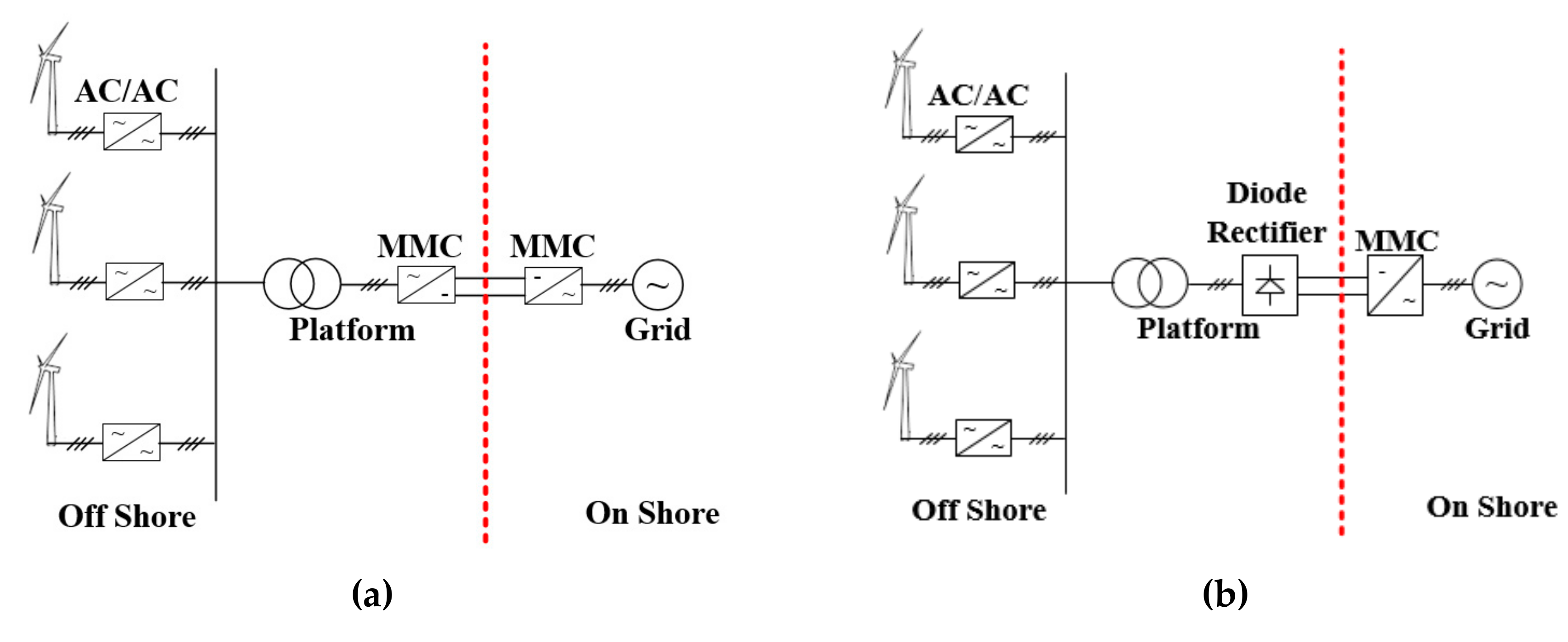
2. Modeling of the OWF System
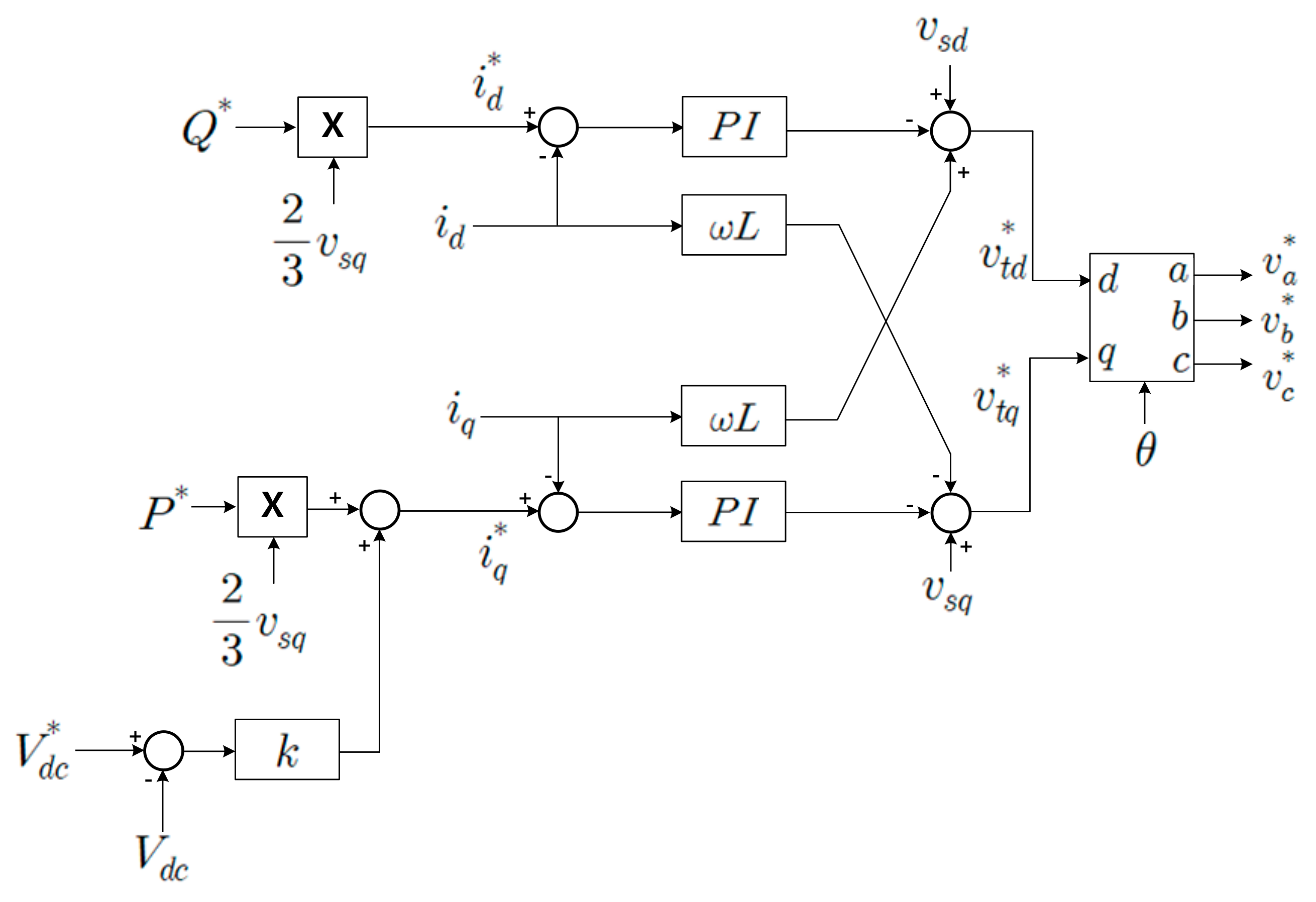
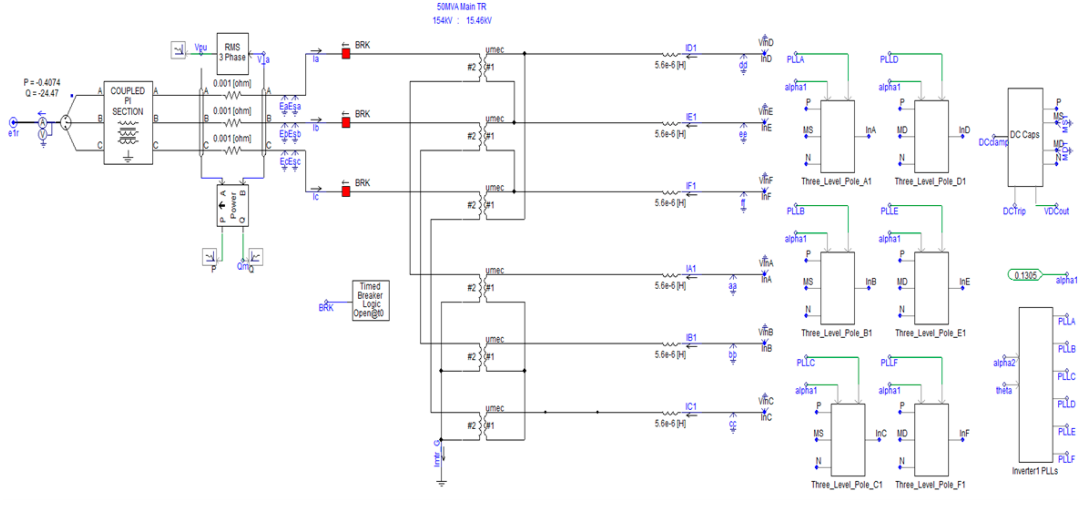
2.1. Onshore MMC Station
An MMC is a type of voltage sourced converter (VSC), as shown in Figure 2. Using this concept, it is possible to make a huge capacity VSC [11]. In this case, the MMC plays a role as an onshore station of the new OWF by converting DC to AC (Alternative current), Figure 3. To transfer, MMC has three controllers, which are a current, a circulation current, and a capacitor balancing controllers [12,13,14,15,16,17,18,19,20]. Using the Park’s transformation theory to control that, the terminal voltage of MMC in the dq axis can be calculated as
where vt and vs are the terminal and grid voltage. i is the three-phase current. R and L are the resistance and inductance, respectively. p is the differential operator. ω is the grid angular frequency. If the PI controller is used, the current controllers will be expressed as
where superscript of * denotes reference mark. Then, i*d and i*q are decided by
where P* and Q* are the real and reactive power, respectively. In this simulation, P* will be the summation of the generated power from the OWF. Q* will be zero to make the unity power factor. k is the coefficient for the dc link voltage control to maintain a stable range of it, as illustrated in Figure 3.
vtd = −Rid − pLid + vsd + ωLiq
vtq = −Riq − pLiq + vsq − ωLid
v*td = − (Kp + Ki/ s) (i*d − id) + vsd + ωLiq
v*tq = − (Kp + Ki /s) (i*q − iq) + vsq − ωLid
i*d = 2Q*/ (3 vsq)
i*q = 2P*/ (3 vsq) + k (V*dc − Vdc)
Figure 2.
Basic structure of a modular multilevel converter (MMC): (a) Topology; (b) Submodule.
Figure 3.
Current controller of MMC in an onshore station.
The MMC needs a circulation current controller to suppress it because it always occurs from the difference of capacitor voltages among phases. To mitigate circulation current, the differential voltage of the MMC in the dq frame can be written as
where vdiff is the differential voltage. R0 and L0 are the resistance and inductance of arm inductors, respectively. icir is the circulating current. If the PI controller is adapted to the circulating current controller, as shown in Figure 4, it will be expressed as
vdiffd = R0icird + pL0icird − 2ωL0icirq
vdiffq = R0icirq − pL0icirq + 2ωL0icird
v*diffd = − (Kp + Ki/s) (i*cird − icird) − 2ωL0icirq
v*diffq = − (Kp + Ki/s) (i*cirq − icirq) + 2ωL0icird
Figure 4.
Circulating current controller of MMC in an onshore station.
The final reference value will be generated as a PWM (Pulse width modulation) switching signal, then it will be decided by a capacitor balancing controller depending on sorted capacitor voltages. The parameters of the MMC are as described in Table 1.
Table 1.
Parameters of an MMC.
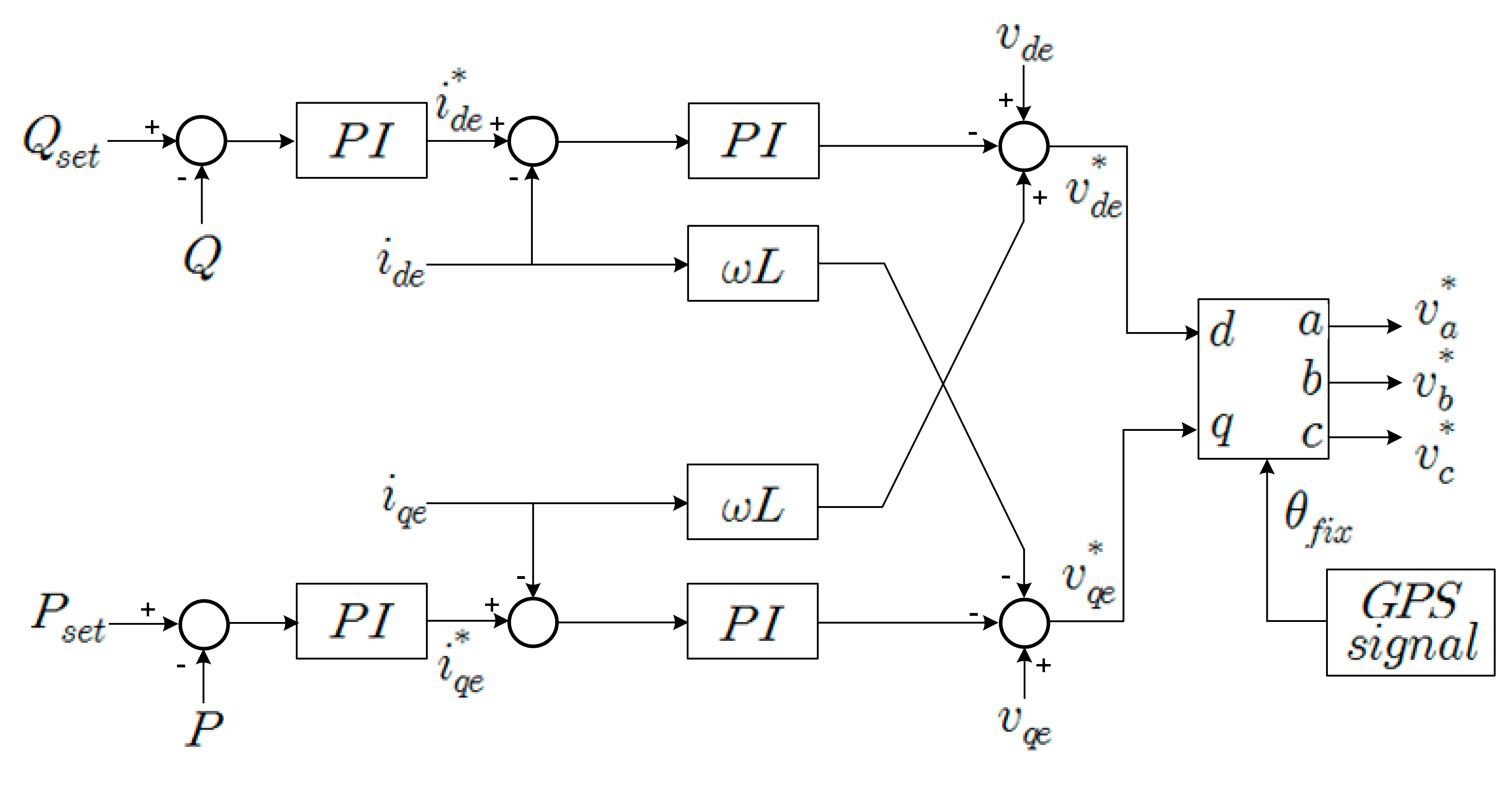
2.2. Offshore Diode Rectifier Station
To convert AC power from the wind power generator to DC power, an offshore DR station should be connected to the DC link of the onshore MMC station, as shown in Figure 5. It consists of a DR, AC filter, and phase-shifting transformers. The phase-shifting transformer can reduce the ripple voltage of the DC link. Through a series connection with them, the DC voltage will be increased to rated voltage. The parameters of the DR station are shown in Table 2.
Figure 5.
Simulation model of diode rectifier (DR) (Offshore side rectifier).
Table 2.
Parameters of diode rectifier (DR) station.
2.3. Wind Turbine
In this analysis case, the simulation model of the offshore wind farm will be used as equivalent models to simplify the simulation model, i.e., 20 MW 2 level VSC, as illustrated in Figure 6, is assumed as four wind turbines each with a capacity of 5 MW. Although the wind turbines are replaced with the equivalent models, its controller will be quite similar to the detailed model, i.e., the current controller, which is similar to the MMC model, will be applied to the equivalent model. There is one problem of the controller in a wind turbine because the uncontrolled DR station cannot generate reference voltage signals and phase angle. It means that it is impossible to perform voltage transforming to dq from a 3-phase frame from the DR side converter of a wind turbine. Thus, [8,9,10] proposed the method as known as FixRef control, as illustrated in Figure 7, which uses GPS signal instead of space phasor angle of grid voltage. This study will also use a steady increased time signal, which is an assumed GPS signal.
Figure 6.
Equivalent simulation model of wind turbines in the new OWF.
Figure 7.
Equivalent simulation model of a wind turbine in the new OWF.
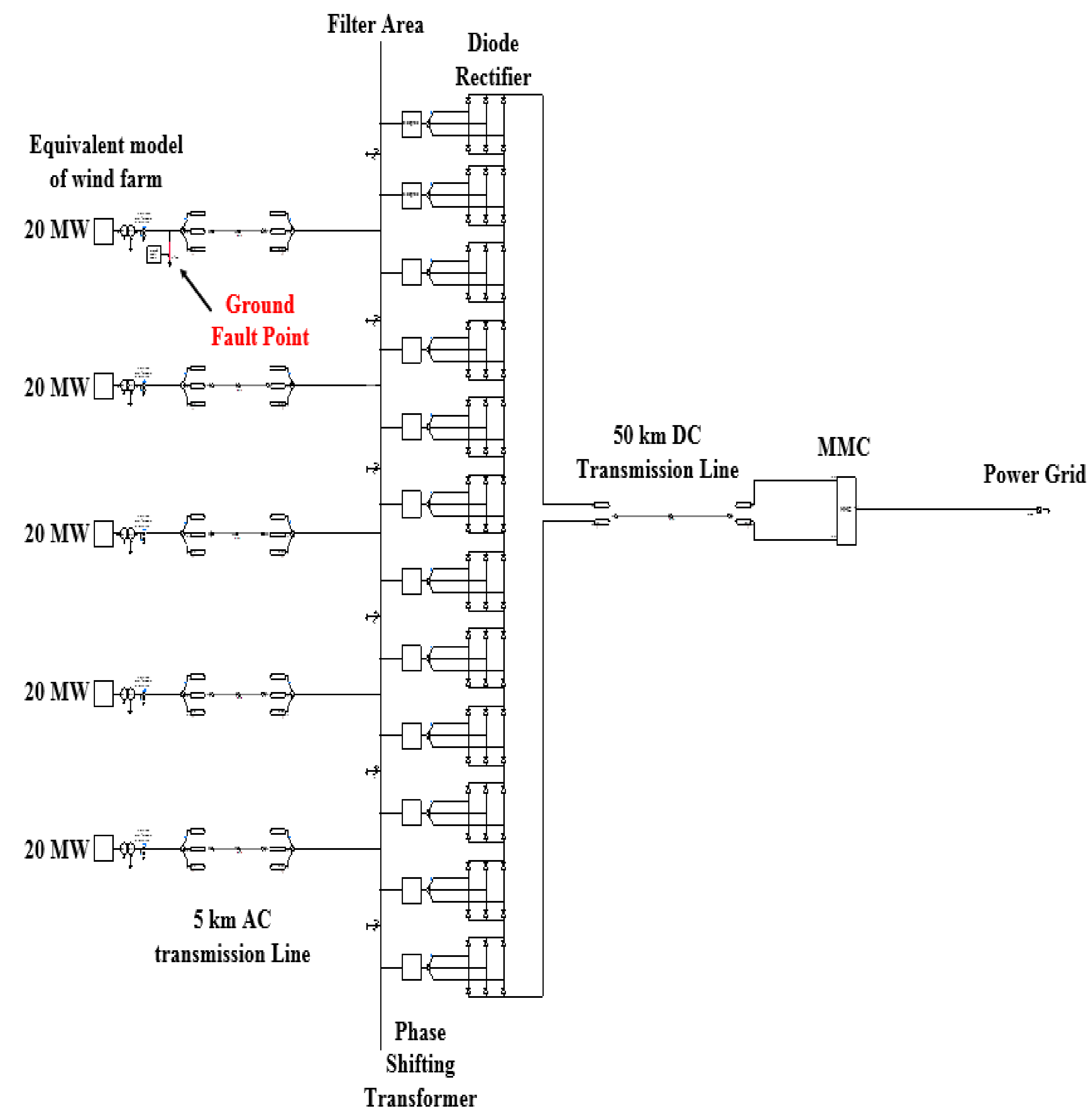
2.4. Whole OWF System
Figure 8 shows the whole simulation model of OWF with DR-HVDC. This system will be attached to the Jeju Island power system as the new OWF, then it will be simulated by parallel computing method in PSCAD/EMTDC program.
Figure 8.
Simulation model of OWF with DR-HVDC.
3. Configuration and Modeling of the Jeju Power System
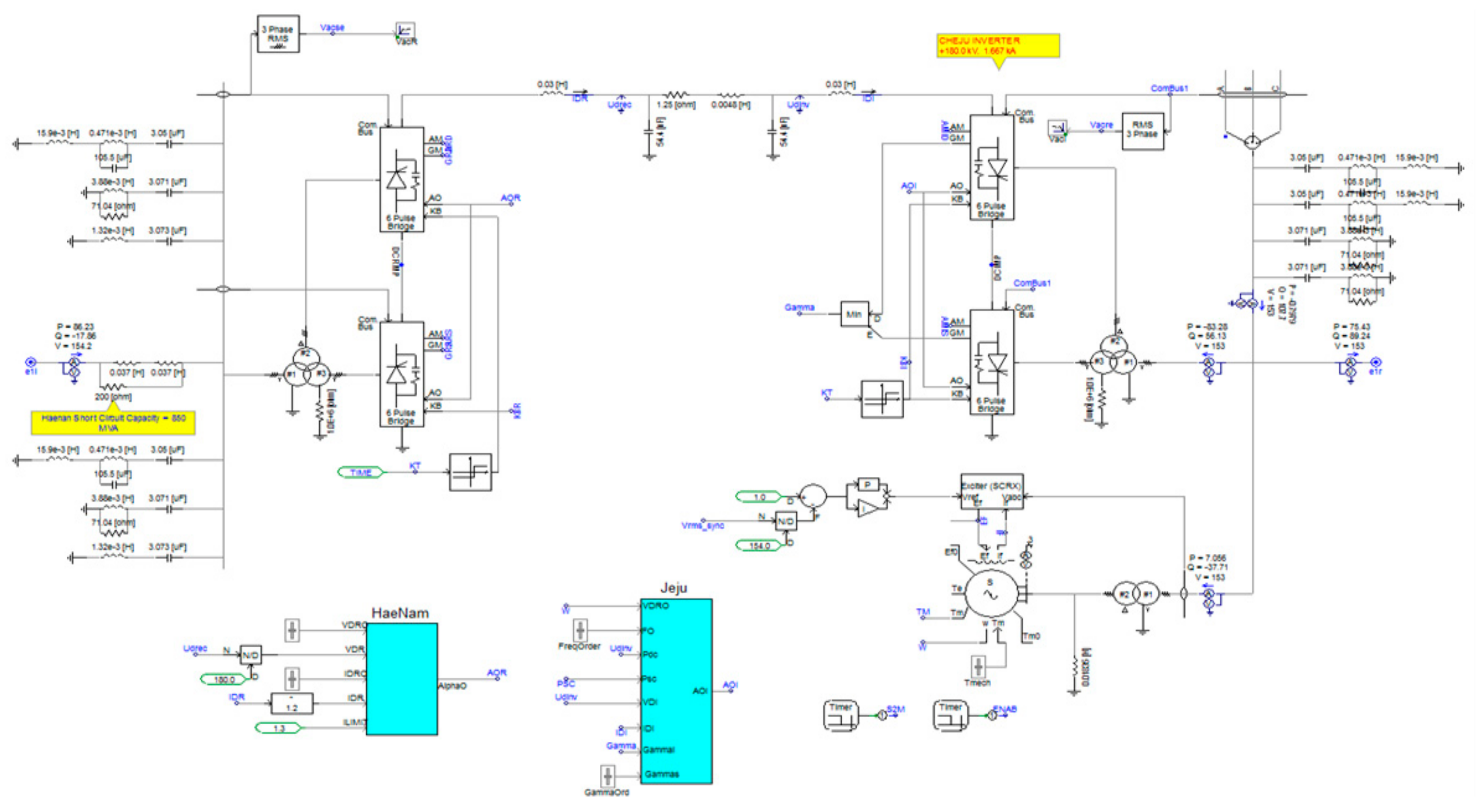
3.1. CSC-HVDC
In the Jeju Island Power system, two CSC-HVDC can operate only as unidirectional. One of which is a frequency regulator, and the other is supplying constant power. Figure 9 represents the simulation model of the CSC-HVDC, which consists of thyristors, a passive filter, a synchronous compensator, and its controller.
Figure 9.
Simulation model of a current source converter high voltage direct current (CSC-HVDC) transmission system.
3.2. Thermal Power Plant
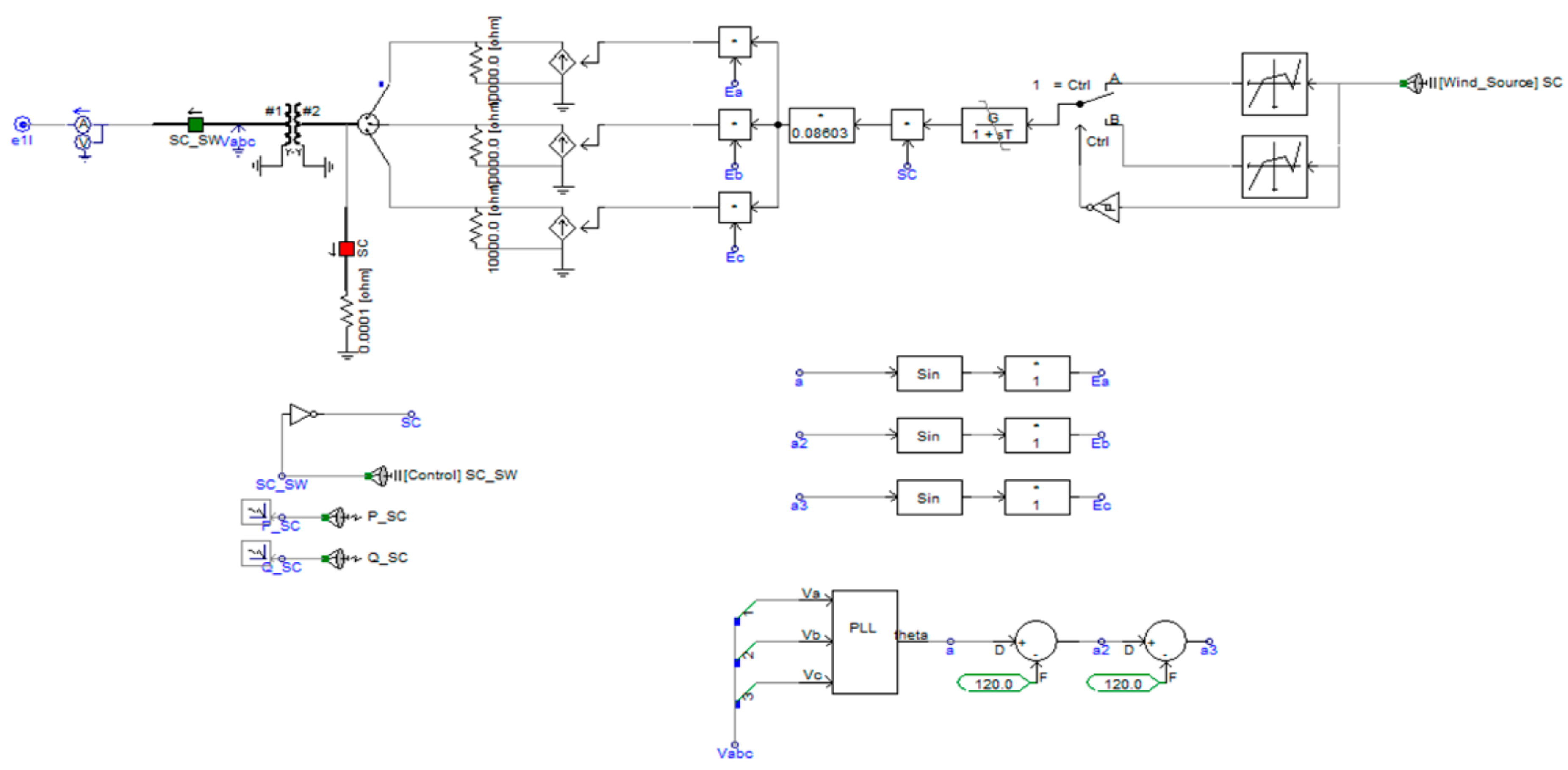
Three thermal power plants in the Jeju Island Power system are also operated separately. In this simulation case, the simplified equivalent controlled current sources are applied, as seen in Figure 10. The measured data will be used to operate this model.
Figure 10.
Simulation model of a thermal power plant.
3.3. STATCOM
The Jeju Island power system has two STATCOM, each with a capacity of 50 MVar. They have an important role with respect to grid voltage stability in its power system because the CSC-HVDCs consume a lot of reactive power. The simulation models of STATCOM consist of a three-level VSC and its controller, as shown in Figure 11.
Figure 11.
Simulation model of STATCOM.
3.4. Existing Wind Farms
The simulation models of existing wind farms with approximately 250 MW are used as controlled current source equivalent model, which can adjust active and reactive powers easily in a simulation program. Thus, the measured data in the Jeju Island power system will be input data of this model, as seen in Figure 12.
Figure 12.
Simulation model of an existing wind farm.
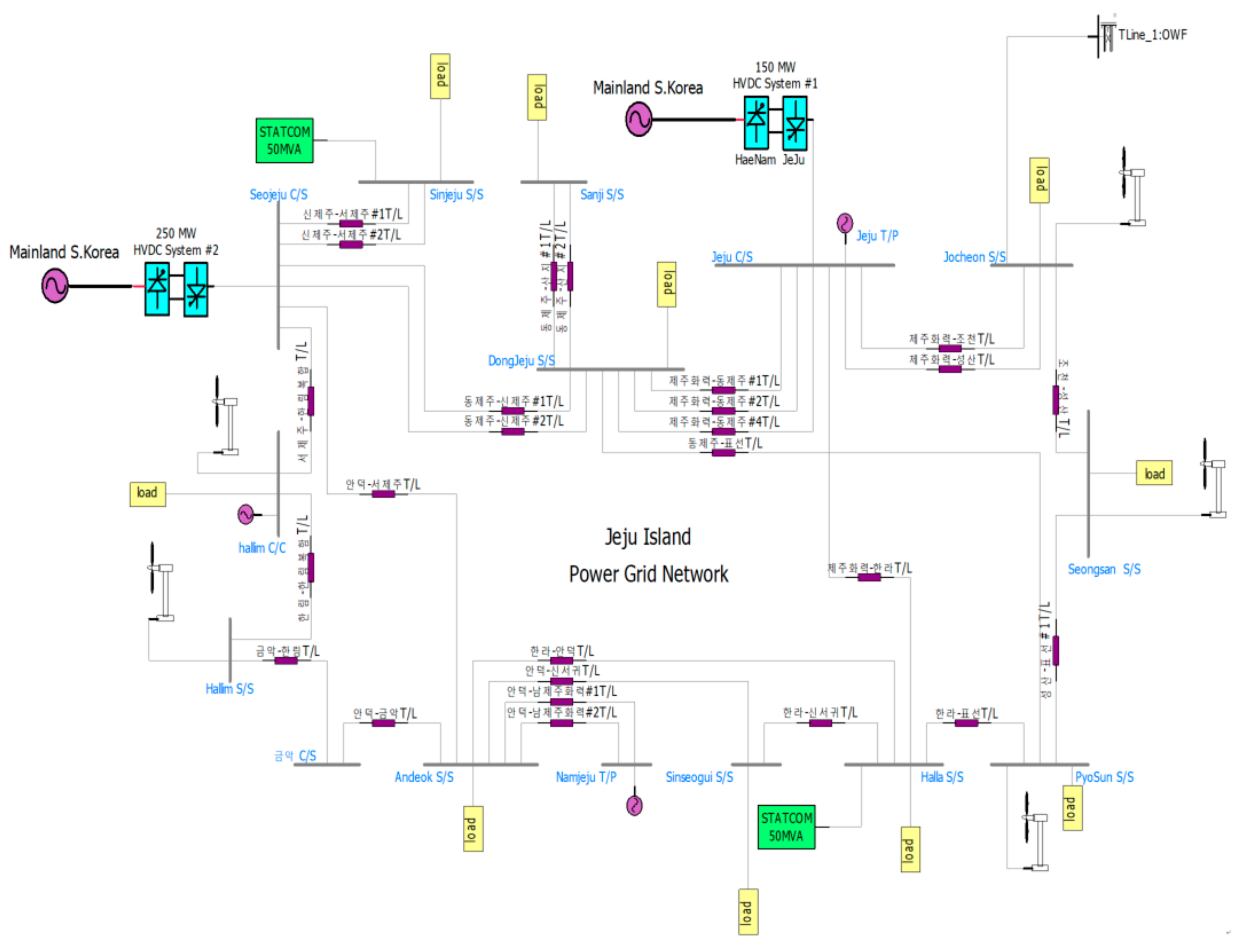
3.5. Whole Simulation Model Including the New OWF
Figure 13 shows the whole simulation model of the Jeju Island power system. The red line represents the connecting point of the new OWF by an electric network interface (ENI), as located in the top left of Figure 13, which supports the parallel computing part in PSCAD/EMTDC. The time scale of the whole simulation is assumed to be 0.14 milli-times by adjusting the time constant of every component. The actual parameters and configurations of the transmission line are applied to this system.
Figure 13.
Simulation model of overall Jeju Island power system.
4. Simulation Results
Because there are many components of the Jeju Island power system, the line colors should be noted as the following colors in Table 3. This line color will be applied to every simulation result of active and reactive power.
Table 3.
Expressions of simulation results.
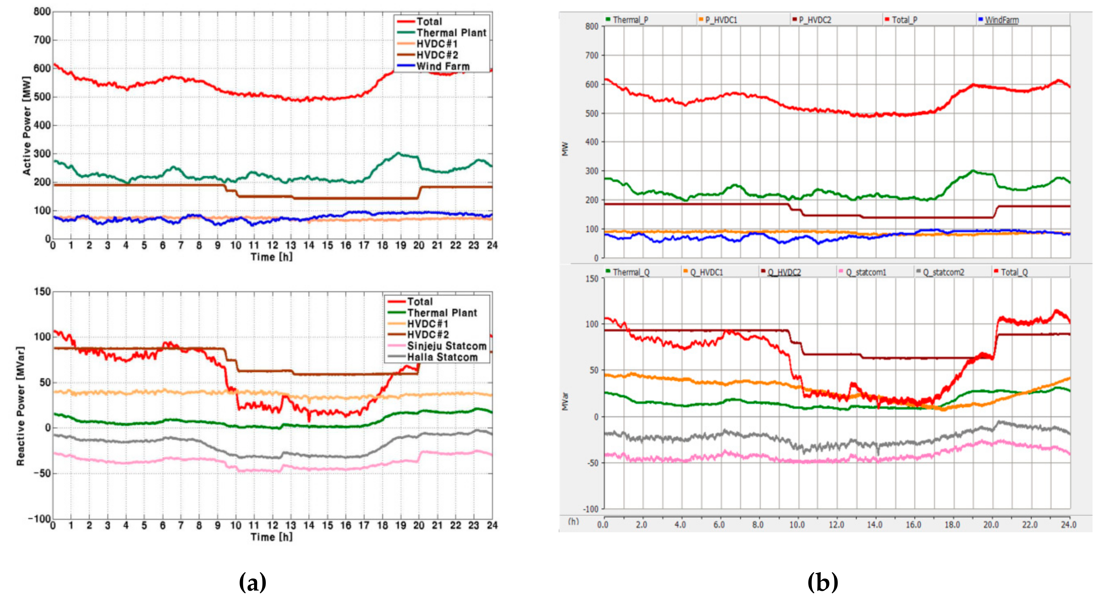
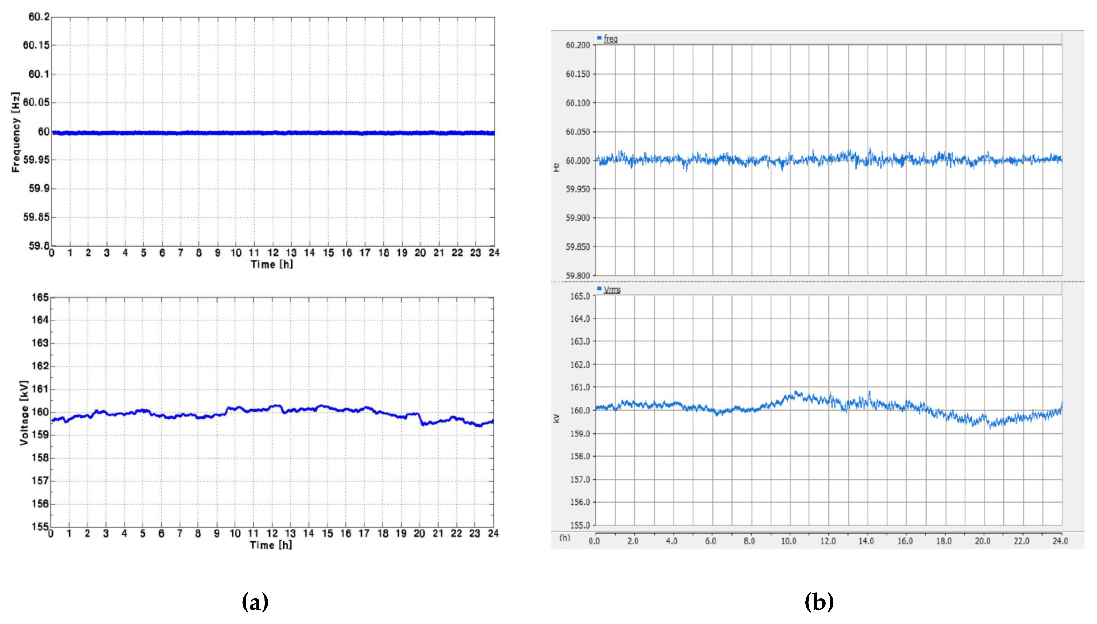
4.1. Case 1: Normal Operation of the Jeju Power System without 100 MW OWF
To confirm the accuracy of the base simulation model, this scenario was conducted. Figure 14, representing active and reactive power at the top and bottom, respectively, shows measured data and simulation results. The top and bottom of Figure 15 represent the grid frequency and voltage. Hence, the errors between the simulation results and the measured data were less than 1% by grid frequency and voltage.
Figure 14.
The simulation results of case 1: (a) Measured data in the Jeju Island power system (top: Active power, bottom: Reactive power); (b) The simulation model (top: Active power, bottom: Reactive power).
Figure 15.
The simulation results of case 1: (a) Measured data in the Jeju Island power system (top: Grid frequency, bottom: Grid voltage measured at the biggest power load); (b) The simulation model (top: Grid frequency, bottom: Grid voltage measured at the biggest power load).
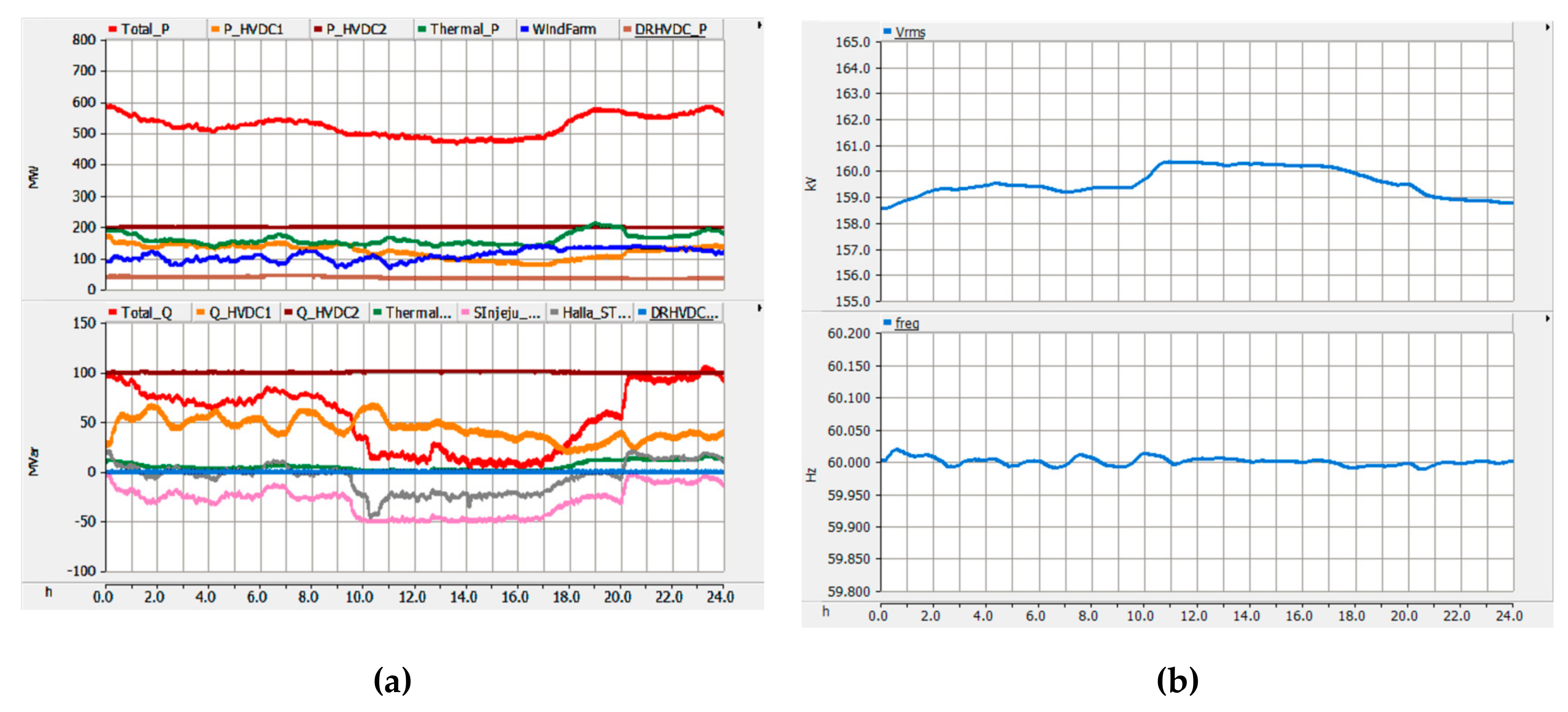
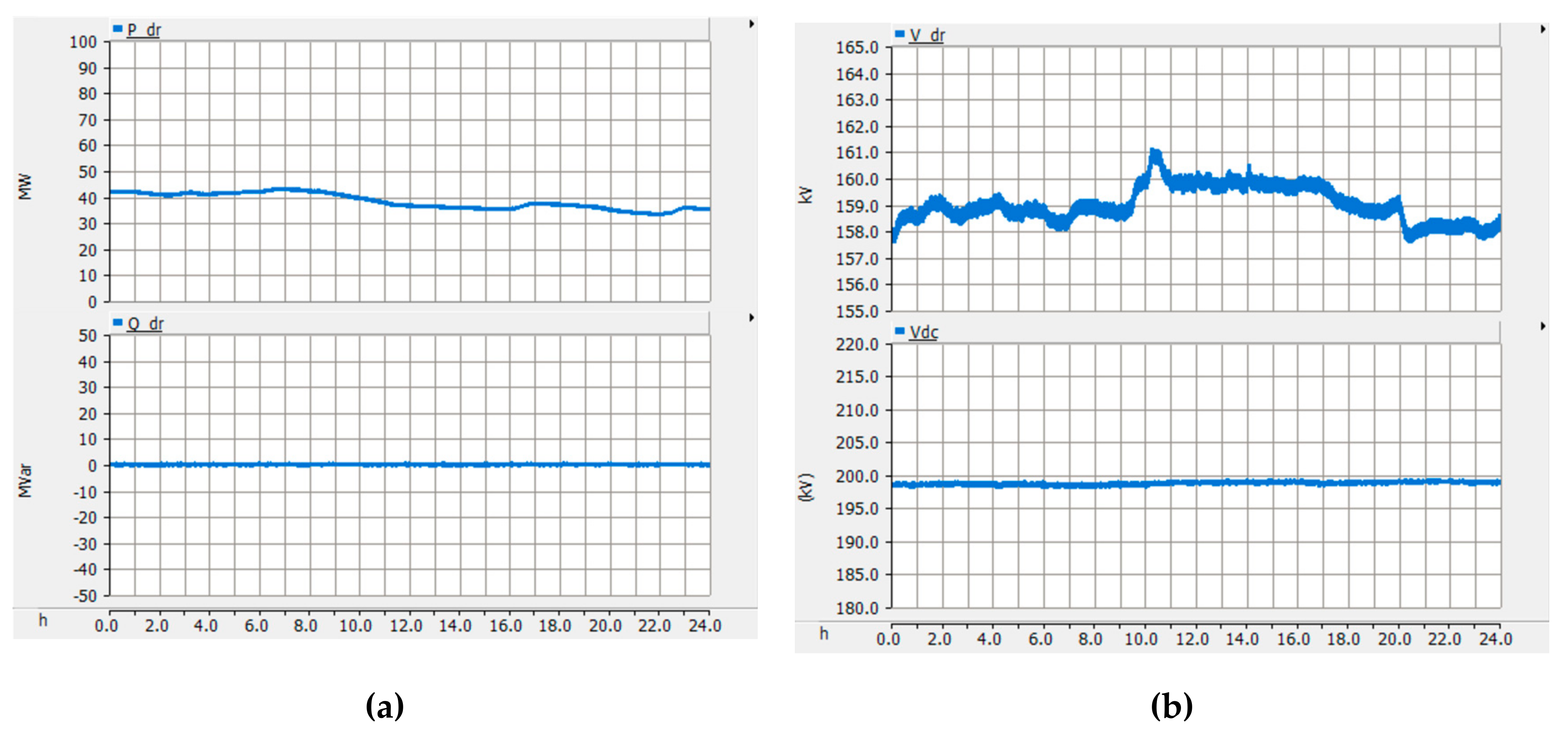
4.2. Case 2: Normal Operation of the Jeju Power System with a New 100 MW OWF Based on DR-HVDC
In the second scenario, the new 100 MW OWF was connected to the Jeju Island power system newly. In contrast to the first scenario, the CSC-HVDC #2 was operated at a limited minimum power, and the thermal power plants also reduced the output power, because the new OWF had generated additional active power. The CSC-HVDC #1 adjusted output power following demand power load and output from the wind farm to stabilize the grid frequency, as seen in Figure 16a. Due to the operation of CSC-HVDC #1, the grid frequency was in the grid code of South Korea from 59.8 Hz to 60.2 Hz. The maximum variance of frequency was slightly increased to 60.02 Hz, as compared to the first case. The variance of voltage was also higher in case 2 than in case 1 without the operation of the new OWF by approximately 2 kV, as shown in Figure 16b.
Figure 16.
The simulation results of case 2: (a) top: Active power, bottom: Reactive power; (b) top: Grid frequency, bottom: Grid voltage measured at the biggest power load.
Figure 17a shows simulation results focused on DR-HVDC. Its reactive power was maintained to the unity power factor. The DC link voltage of DR-HVDC was in a constant value of 200 kV regardless of the active and reactive power, as seen in Figure 17b.
Figure 17.
The simulation results of case 2: (a) top: Active power of DR HVDC, bottom: Reactive power of DR HVDC; (b) top: AC voltage measured at DR HVDC connection point, bottom: DC link voltage of DR HVDC.
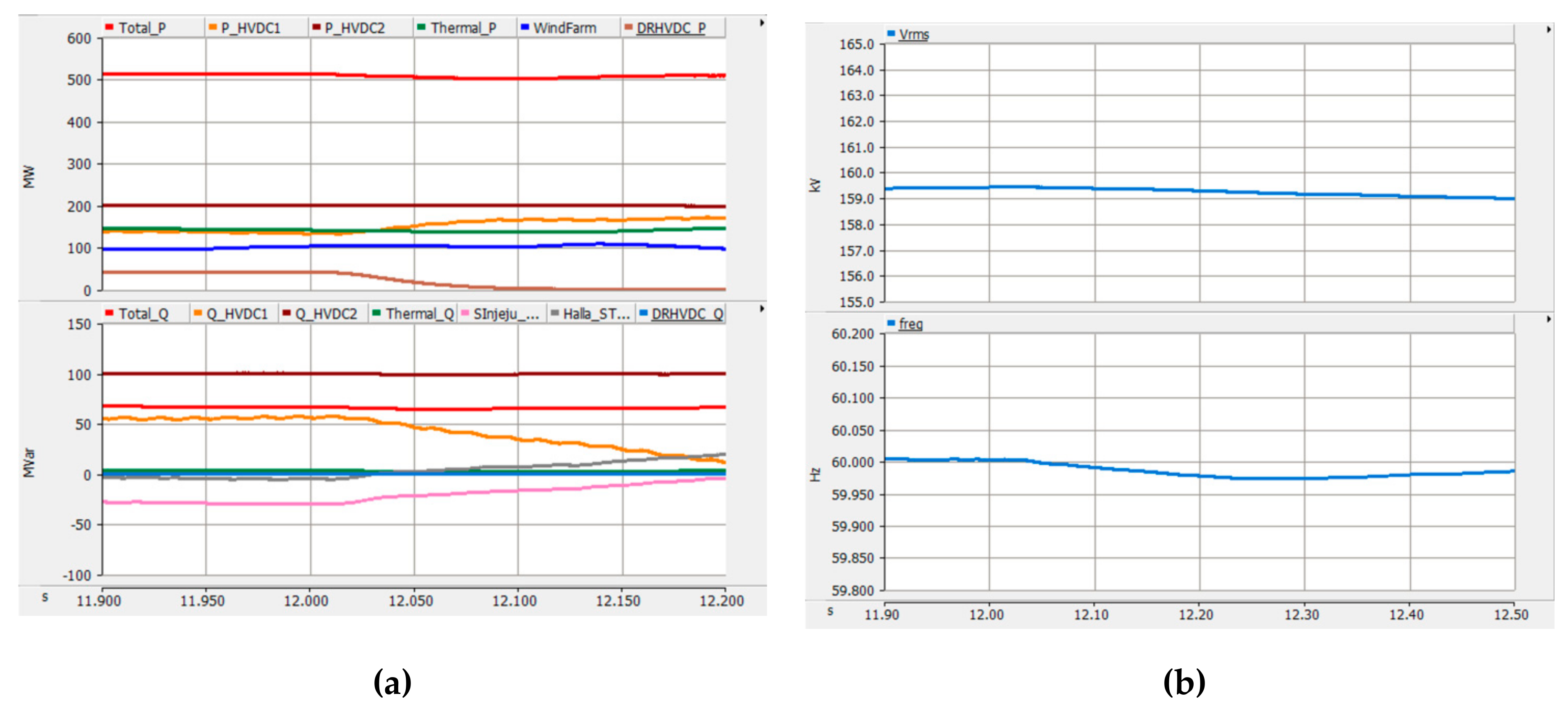
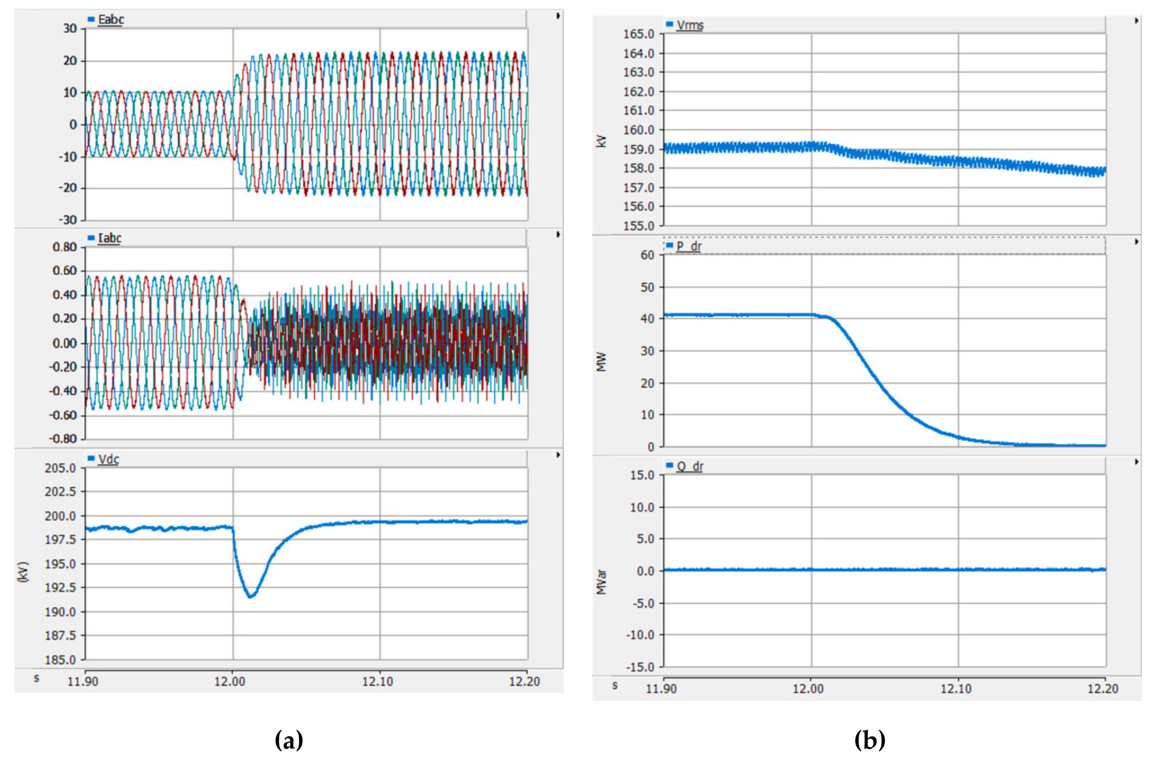
4.3. Case 3: Disconnection Fault Occurred at the DC Transmission Line
In the third scenario, the DC submarine cable was disconnected abruptly. Thus, the output power of DR-HVDC was zero suddenly, and then the HVDC #1 compensated, as shown in Figure 18a. From this fault condition, the frequency and voltage were dropped to 59.97 Hz and 158 kV, as seen in Figure 18b, respectively. The DC link voltage of DR-HVDC also had a 5% variance. The AC voltage was recorded at the OWF grid by converter operation of wind turbines, as shown in Figure 19a. Figure 19b presents the onshore output of the DR-HVDC, whose active power was reduced to zero because of disconnection fault.
Figure 18.
The simulation results of case 4: (a) top: Active power, bottom: Reactive power; (b) top: Grid frequency, bottom: Grid voltage measured at the biggest power load.
Figure 19.
The simulation results of case 4: (a) top: Instantaneous voltage measure at the OWF grid, middle: Instantaneous current measure at the OWF grid, bottom: DC link voltage of DR-HVDC; (b) top: AC voltage measured at DR HVDC connection point, middle: Active power of DC-HVDC, bottom: Reactive power of DR-HVDC.
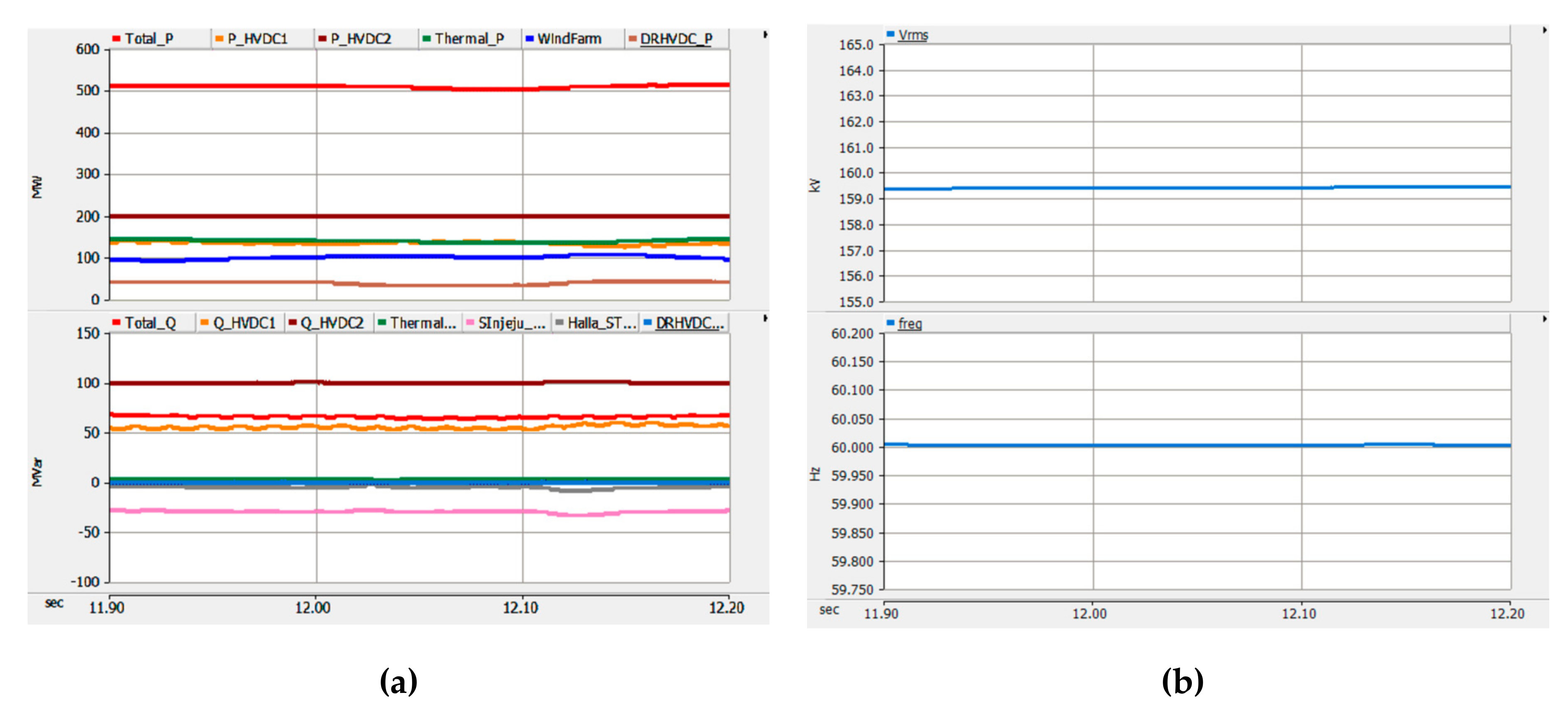
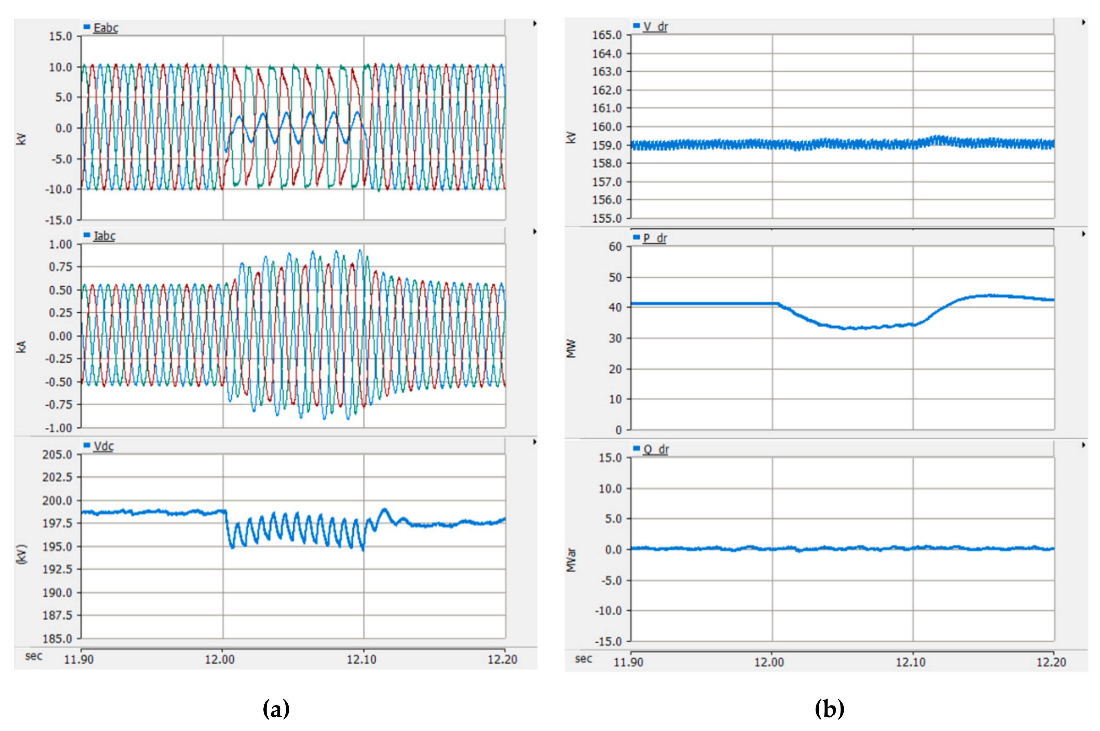
4.4. Case 4: Single Line Ground Fault Occurred at AC Line in the New 100 MW OWF
From the simulation results of case 4, the DR-HVDC was able to protect the Jeju Island power system from an OWF side fault. Although the voltage and current of the OWF side power grid were oscillated, as shown in Figure 21a, the voltage and frequency of the Jeju Island power system was stable, as seen in Figure 20b. The active power dropped at 35 MW, as illustrated in Figure 21b, then the CSC-HVDC #1 compensated that immediately, as seen in Figure 20a.
Figure 20.
The simulation results of case 4: (a) top: Active power, bottom: Reactive power; (b) top: Grid frequency, bottom: Grid voltage measured at the biggest power load.
Figure 21.
The simulation results of case 4: (a) top: Instantaneous voltage measure at OWF grid, middle: Instantaneous current measure at OWF grid, bottom: DC link voltage of DR-HVDC; (b) top: AC voltage measured at DR HVDC connection point, middle: Active power of DC-HVDC, bottom: Reactive power of DR-HVDC.
5. Conclusions
This study proposed installation of a DR-HVDC for the new 100 OWF in the Jeju Island power system. To confirm the impact of the DR-HVDC, the simulation model of the present Jeju Island power system was conducted and compared with the actual power system operating history in the first case. From the analysis results of the second case, its power system had been linked with the OWF by using the DR-HVDC. And it was able to operate a steady state when the DR-HVDC transferred the output power of the OWF. In addition, this study also checked on the DR-HVDC in transient state. Although the disconnection fault of the DC transmission line, which is one of the common incidents of an HVDC, occurred, the unidirectional HVDC in the Jeju Island power system was able to compensate for the dropped active power of the OWF by a fast response characteristic in the third case. This study also analyzed the ground fault impact of an offshore AC grid in the last case. Then, the analysis confirmed that the DR-HVDC can be helpful in reducing fault impact. From the results in steady and transient states, although the DR-HVDC was operated by using an uncontrolled rectifier at the offshore station and only one MMC at the onshore side, it was able to play a role as a conventional HVDC even in the small and isolated power system. Consequently, the application of the DR-HVDC in a small power system is reasonable to reduce costs and increase the reliability of an OWF instead of a conventional HVDC. If in the future, the new OWF in the Jeju Island power system is connected with a DR-HVDC, the power system will be more stable than the AC connection method and save costs than conventional HVDC topology.
Author Contributions
Conceptualization: S.-H.S. and E.-H.K. Methodology: S.H.C. and M.H.K. Resources: S.H.C., S.-H.S., and E.-H.K. Writing—original draft preparation: S.H.C. and M.H.K. Writing—review and editing: S.H.C. and E.-H.K. Supervision: S.-H.S. and E.-H.K.
Funding
This research was funded by KETEP and KEPCO, respectively.
Acknowledgments
This work was supported by the Korea Institute of Energy Technology Evaluation and Planning (KETEP) and the Ministry of Trade, Industry & Energy (MOTIE) of the Republic of Korea (No. 20173010024890) and Korea Electric Power Corporation (Grant number: R18XA03), respectively.
Conflicts of Interest
The authors declare no conflict of interest.
References
- Jeju Special Self-Governing Province. Carbon Free Island Jeju by 2030, Policy Report; Jeju Special Self-Governing Province: Jeju Island, Korea, 2012.
- Muyeen, S.M.; Takahashi, R.; Murata, T.; Tamura, J. Multi-Converter Operation of Variable Speed Wind Turbine Driving Permanent Magnet Synchronous Generator during Network Fault. In Proceedings of the 2008 International Conference on Electrical Machines and System, Tokyo, Japan, 15–18 November 2009. [Google Scholar] [CrossRef]
- Bahrman, M.P. HVDC transmission overview. In Proceedings of the 2008 IEEE PES Transmission and Distribution Conference and Exposition, Chicago, USA, 21–24 April 2008. [Google Scholar] [CrossRef]
- Reed, G.F.; Al Hassan, H.A.; Korytowski, M.J.; Lewis, P.T.; Grainger, B.M. Comparison of HVAC and HVDC solutions for offshore wind farms with a procedure for system economic evaluation. In Proceedings of the 2013 IEEE Energytech, Cleveland, OH, USA, 21–23 May 2013; pp. 1–7. [Google Scholar] [CrossRef]
- Liu, H.; Chen, Z. Contribution of VSC-HVDC to frequency regulation of power system with offshore wind generation. IEEE Trans. Energy Convers. 2015, 30, 918–926. [Google Scholar] [CrossRef]
- Elliott, D.; Bell, K.R.W.; Finney, S.J.; Adapa, R.; Brozio, C.; Yu, J.; Hussain, K. A comparison of AC and HVDC options for the connection of offshore wind generation in Great Britain. IEEE Trans. Power Deliv. 2016, 31, 798–809. [Google Scholar] [CrossRef]
- Parastar, A.; Seok, J.-K. High-Power-Density Power Conversion System for HVDC-Connected Offshore Wind Farms. J. Power Electron. 2013, 13, 737–745. [Google Scholar] [CrossRef]
- Cristian, N.; Hans-Gunter, E.; Sven, A.; Friedemann, A. Auxiliary Power Supply in a FixRef Controlled Offshore Wind Power Plant with Diode Rectifier HVDC Transmission. In Proceedings of the 16th Int’l Wind Integration Workshop, Berlin, Germany, 25–27 October 2017. [Google Scholar]
- Seman, S.; Zurowski, R.; Taratoris, C. Interconnection of Advanced Type 4 WTGs with Diode rectifier based HVDC Solution and Weak AC Grids. In Proceedings of the 14th Wind Integration Workshop, Brussels, Belgium, 20–22 October 2015. [Google Scholar]
- Prignitz, C.; Eckel, H.G.; Rafoth, A. FixRef Sinusoidal Control in Line Side Converters for Offshore Wind Power Generation. In Proceedings of the 2015 IEEE 6th International Symposium on Power Electronics for Distributed Generation System, Aachen, Germany, 22–25 June 2015. [Google Scholar] [CrossRef]
- Marquardt, R.; Lesnicar, A.; Hildinger, J. Modulares stromrichterkonzept für netzkupplungsanwendungen bei hohen spannungen. In Proceedings of the ETG Conference; ETG-Fachtagung: Bad Nauheim, Germany, 2002. [Google Scholar]
- Lesnicar, A.; Marquardt, R. An innovative modular multilevel converter topology suitable for a wide power range. In Proceedings of the Power Tech Conference, Bologna, Italy, 23–26 June 2003. [Google Scholar] [CrossRef]
- Ilves, K.; Antonopoulos, A.; Norrga, S.; Nee, H.-P. Steady-state analysis of interaction between harmonic components of arm and line quantities of modular multilevel converters. IEEE Trans. Power Electron. 2012, 27, 57–68. [Google Scholar] [CrossRef]
- Song, Q.; Liu, W.; Li, X.; Rao, H.; Xu, S.; Li, L. A steady-state analysis method for a modular multilevel converter. IEEE Trans. Power Electron. 2013, 28, 3702–3713. [Google Scholar] [CrossRef]
- Zhang, Y.; Adam, G.P.; Lim, T.C.; Finney, S.J.; Williams, B.W. Analysis and Experiment Validation of a Threelevel Modular Multilevel Converters. In Proceedings of the 8th International Conference on Power Electronics—ECCE Asia, Jeju, Korean, 29 May–2 June 2011. [Google Scholar] [CrossRef]
- Tu, Q.; Xu, Z.; Chang, Y.; Guan, L. Suppressing DC voltage ripples of MMC-HVDC under unbalanced grid conditions. IEEE Trans. Power Deliv. 2012, 27, 1332–1338. [Google Scholar] [CrossRef]
- Guam, M.; Xu, Z. Modeling and control of a modular multilevel converter-based HVDC system under unbalanced grid conditions. IEEE Trans. Power Electron. 2012, 27, 4858–4867. [Google Scholar] [CrossRef]
- Rohner, S.; Bernet, S.; Hiller, M.; Sommer, R. Modulation, losses, and semiconductor requirements of modular multilevel converters. IEEE Trans. Ind. Electron. 2010, 57, 2633–2642. [Google Scholar] [CrossRef]
- Guan, M.; Xu, Z.; Chen, H. Control and modulation strategies for modular multilevel converter based HVDC system. In Proceedings of the IECON 2011—37th Annual Conference on IEEE Industrial Electronics Society, Melbourne, VIC, Australia, 7–10 November 2011. [Google Scholar] [CrossRef]
- Yang, X.; Li, J.; Wang, X.; Fan, W.; Zheng, T.Q. Circulating current model of modular multilevel converter. In Proceedings of the 2011 Asia-Pacific Power and Energy Engineering Conference (APPEEC), Wuhan, China, 25–28 March 2011. [Google Scholar]
© 2019 by the authors. Licensee MDPI, Basel, Switzerland. This article is an open access article distributed under the terms and conditions of the Creative Commons Attribution (CC BY) license (http://creativecommons.org/licenses/by/4.0/).