Abstract
This study focuses on improving the power density of a spherical multi-degree-of-freedom (multi-DOF) actuator. A spherical multi-DOF actuator that can operate in three DOFs is designed. The actuator features a double air gap to reduce eddy current loss. However, a multi-DOF actuator driven by a single actuator exhibits low power density. Therefore, a Halbach magnet array is applied to improve the power density of a spherical multi-DOF actuator, and its output characteristics are compared with those of an existing spherical multi-DOF actuator via finite element analysis. Additionally, the output characteristics are analyzed based on changes in the coil pitch angle and magneto-motive force of the rotating winding. Furthermore, it is necessary for a spherical multi-DOF actuator to move to the command position. Hence, a stability analysis is performed to ensure that the spherical multi-DOF actuator is stably driven based on the command position.
1. Introduction
Recently, a significant amount of interest has been directed toward the robot industry owing to the advent of the fourth industrial revolution. Currently, one-degree-of-freedom (DOF) systems require one actuator, whereas three-DOF systems require three actuators. For systems with two or more DOFs, an additional structure is required to connect the actuators [1,2,3]. Most applications that implement such multi-DOF systems by connecting multiple actuators include robotic joints [4,5] and drone gimbal systems [6,7]. However, the volume of the systems is high, and this constitutes a problem. Therefore, several studies have focused on developing actuators capable of being driven in multiple axes [8,9,10,11,12,13].
Based on extant studies, two types of multi-DOF actuators and motors are known to be driven in multiple axes, namely the permanent-magnet-type [14,15,16,17] and induction-type multi-DOF actuators [18]. Permanent-magnet-type multi-DOF actuators exhibit the advantage of large magnetic flux density. Additionally, most of these actuators are designed with tooth-concentrated windings to improve power density. However, for induction-type multi-DOF actuators, distributed windings are required to decrease the effects of harmonics such as crawling phenomena. Thus, most studies tend to focus on the structure of a permanent-magnet-type multi-DOF actuator.
Furthermore, multi-DOF actuators are divided into core-type actuators [19,20] and slotless-type actuators [12,18]. A core-type multi-DOF actuator exhibits the advantage of low-leakage magnetic flux because magnetic flux mainly flows through the iron core, which has high permeability. Conversely, a slotless-type multi-DOF actuator suffers from the disadvantage of a high leakage of magnetic flux due to the absence of an iron core within the winding. However, the slotless multi-DOF actuator is advantageous in terms of position control given the absence of a reluctance difference between the stator and rotor. Multi-DOF motors also exist in the form of ultrasonic motors [21,22,23] and bearingless motors [16].
Several studies have focused on multi-DOF actuators. However, most multi-DOF actuators exhibit low power density. Moreover, multi-DOF actuators are multi-axis driven, in contrast to conventional actuators or motors; thus, losses due to changes in magnetic flux in multi-DOF actuators are high.
In this study, a dual-airgap slotless-type spherical multi-DOF actuator was developed, as shown in Figure 1, with the aim to decrease eddy current loss by simultaneously moving internal and external rotors. In Section 2, the theory of dual-airgap slotless-type spherical multi-DOF actuator is discussed. As explained in Section 3, a Halbach magnet array was applied to the actuator to improve output characteristics.
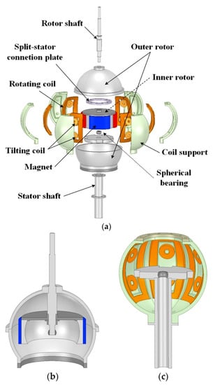
Figure 1.
Structure of the dual-airgap slotless- type spherical multi-degree-of-freedom (multi-DOF) actuator: (a) Full model; (b) Rotor part; (c) Stator part.
2. Theory of Dual-Airgap Slotless-Type Spherical Multi-DOF Actuator
2.1. Operation of the Spherical Multi-DOF Actuator
The structure of the dual-airgap slotless-type spherical multi-DOF actuator is shown in Figure 1. Figure 1a shows the structure of the full model. Figure 1b,c show the structure of the rotor and stator parts. As shown in Figure 1a,b, the actuator consists of two rotors to decrease eddy current losses. Additionally, the material used for the inner rotor’s back yoke and outer rotor was steel 1001. The inner rotor features a surface permanent magnet to form the main magnetic flux. The outer rotor is utilized to decrease the leakage of the magnetic flux by creating paths for the magnetic flux. It is connected to the inner rotor by the rotor shaft and both rotors move simultaneously. If the back yoke is applied to the stator as opposed to the outer rotor, then the magnetic flux leakage is low and a magnetic flux path is formed; however, the eddy current loss due to the back yoke of the stator increases. Therefore, the outer rotor replaces the back yoke of the stator, and the resulting structure is capable of decreasing eddy current loss. The rotor and stator shafts are separated using a spherical bearing for three-axis operation. The stator windings are composed of rotating coils and tilting coils for rotation and tilting, respectively. Additionally, a plastic-material coil support is used to wind the coil to the desired position.
Figure 2 shows the movement of the dual-airgap slotless-type spherical multi-DOF actuator during tilting operation. Therein, the dual air gap can be identified. Here, α is a moving angle from the z-axis, β is a moving angle from the x-axis, and δ is an angle from the moving axis to the xy-plane. The actuator moves simultaneously based on α and β command angles because the internal and external rotors are connected to the same rotor shaft. The stator is connected to the stator shaft, but it does not move based on command angles such as α and β.
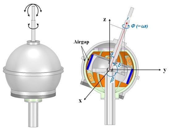
Figure 2.
Operation of the dual-airgap slotless-type spherical multi-DOF actuator.
The basic model specifications of dual-airgap slotless-type spherical multi-DOF actuator are listed in Table 1. The basic model consists of three phases and exhibits low torque and efficiency.

Table 1.
Specifications of the basic model of the dual-airgap slotless-type spherical multi-degree-of-freedom (multi-DOF) actuator.
Rotating and tilting currents flow through the rotating and tilting coils during the operation of the actuator. The rotating currents are equated as follows:
where ir,a, ir,b, ir,c, ir,d, ir,e, and ir,f are the rotating current flowing in the phases from a to f, respectively, and Ir is the maximum value of the rotating current, p is the number of pole pairs, and ωm is the mechanical angular velocity.
The tilting currents are as follows:
where α and β are the position angles of the rotor, itu,a, itu,b, itu,c, itu,d, itu,e, and itu,f are the tilting currents of the upper coils, itd,a, itd,b, itd,c, itd,d, itd,e, and itd,f are the tilting currents of the lower coils, It,m is the maximum value of the tilting current, and θc is the angle of the coil from the xy reference plane.
A common three-phase current flows through the rotating coil to generate a rotating field. The tilting coils are composed of a pair of upper and lower parts. The direction of the current flowing through the upper coil is opposite to that flowing through the lower coil. Additionally, the tilting current is a function of α and β, which are the position angles. Hence, the values of the six pairs of tilting currents change according to the values of α and β.
2.2. Spherical Multi-DOF Actuator Using Halbach Magnet Array Structure
Conventional multi-DOF actuators have low power density. To solve the problem, a Halbach magnet array was added to the existing magnet structure located in the internal rotor, as shown in Figure 3. The Halbach magnet array concentrates magnetic flux and reduces leakage flux.
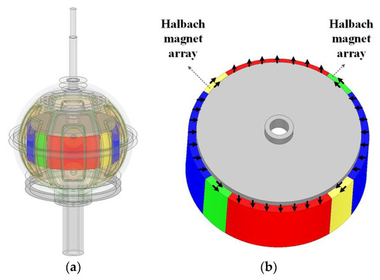
Figure 3.
Spherical multi-DOF actuator using Halbach magnet array: (a) Structure of spherical multi-DOF actuator with the Halbach magnet array; (b) Internal rotor and magnetization direction.
The magnetic flux density of spherical multi-DOF actuator with a Halbach magnet array is equated as follows [23]:
where H is the magnetic field intensity, μ0 is the permeability of free space, μr is the relative permeability of the permanent magnet, Mr is the residual magnetization vector, and μm is the relative permeability of the inner rotor.
The residual magnetization vector of the jth permanent magnet cab be written as follows:
where Lmag is the axial length of permanent magnet and l is the number of segments per pole. This is l = 2.
Based on Equations (10) and (11), the residual magnetization vector and scalar potentials are expressed as follows:
Additionally, the scalar potential Φk is obtained as follows [24]:
where Anm, Bnm, m, and n are determined by boundary conditions, Ynm (α, β) is the spherical harmonic function, and Pn|m| (x) is a function represented by Legendre polynomial.
The distribution of the magnetic field is determined by a spherical harmonic function of Mrr (α, β). Mrr (α, β) as follows:
Therefore, the air-gap magnetic flux density of the spherical multi-DOF actuator with the Halbach magnet array is obtained as follows [23]:
where Br, Bα, and Bβ are the air-gap magnetic flux densities in the r, α, and β directions of the spherical coordinate system, respectively, m and n are determined by boundary conditions, Bnm is the magnetic flux density obtained by the boundary condition, r is the distance from the center of the spherical coordinate system, and Ynm (α, β) is the spherical harmonic function.
3. Power Density Improvement
3.1. Output Characteristics Based on Magnet Array Structure
The dual-airgap slotless-type spherical multi-DOF actuator exhibits different output characteristics based on the magnet array structure. Figure 4 shows the magnetic flux density vector of the internal rotors of the basic model and that of the Halbach magnet array model under a no-load condition for the same pole pitch angle. Additionally, Table 2 summarizes the fundamental wave components of the air-gap magnetic flux density (Bg1) of the basic and Halbach magnet array models. The fundamental wave component of the Halbach magnet array model is larger than that of the basic model because the magnetic flux density is concentrated in a wider area. Furthermore, the fundamental wave of the air-gap magnetic flux density is large in the model with the Halbach magnet array; thus, the output characteristics of the spherical multi-DOF actuator with the Halbach magnet array are excellent. The output characteristics of the basic model and Halbach magnet array model are summarized in Table 3.
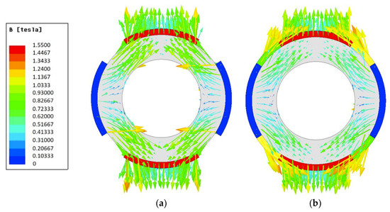
Figure 4.
Magnetic flux density vector of the inner rotor: (a) Basic model; (b) Halbach magnet array model.
Table 2.
Fundamental wave components of air-gap magnetic flux density of the basic model and Halbach magnet array model.
Table 3.
Comparison between the output characteristics of the basic model and Halbach magnet array model.
3.2. Detailed Design of Spherical Multi-DOF Actuator Using Halbach Magnet Array
The rotating coils of the existing spherical multi-DOF actuators exhibit a low fill factor rate. Therefore, the fill factor rate increases based on the arrangement space of the rotating coils in order to improve the power density. Thus, the number of rotating windings increases as shown in Table 4. Furthermore, the output torque increases when the electric load increases.
Table 4.
Comparison of output characteristics with increased the number of rotating windings.
The Halbach magnet array structure concentrates the magnetic flux passing in the direction of the air gap. However, the width of the Halbach magnet is inversely proportional to the width of the dipole magnet magnetized in the radial direction. Therefore, it is important to determine the appropriate pole pitch angle. The magnetic flux is concentrated if the width of the magnet magnetized in the radial direction is smaller than the width of the Halbach magnet. However, the outgoing magnetic flux in the radial direction decreases and the output characteristic is poor.
Figure 5 and Figure 6 show the output characteristics based on pole pitch angle and command position, respectively, of the spherical multi-DOF actuator with Halbach magnet array using the model with improved fill factor rate. As the command angles α and β change, the values of the tilting current and the rotating current change. The average torque and torque ripple rate exhibit excellent characteristics in the pole pitch angle ranges of 140–170 °E and 140–150 °E (°E is the electrical degree), respectively. Additionally, Figure 7 shows the torque waveform according to the pole pitch angle when the command angles are α = 10° and β = 30°. Thus, the model with excellent output characteristics for most command positions and a pole pitch angle of 150 °E are selected for the final model. Table 5 shows the specifications of the final model.
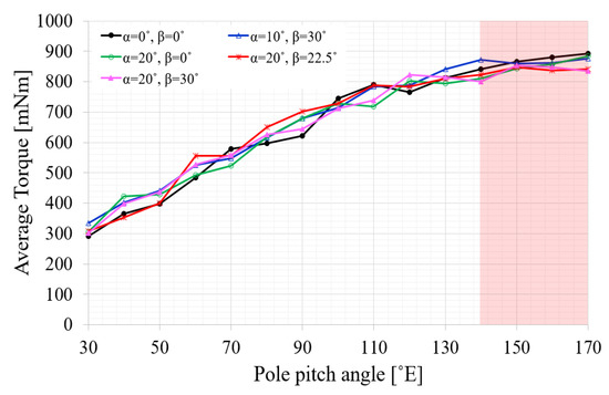
Figure 5.
Average torque of the spherical multi-DOF actuator with Halbach magnet array based on pole pitch angle and command position.
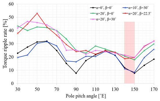
Figure 6.
Torque ripple rate of the spherical multi-DOF actuator with Halbach magnet array based on pole pitch angle and command position.
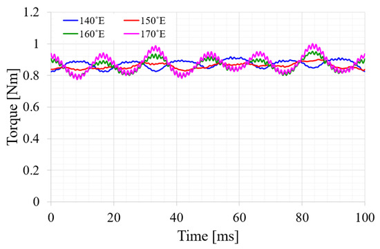
Figure 7.
Torque waveform according to the pole pitch angle at α = 10° and β = 30°.
Table 5.
Specifications of final model of the dual-airgap slotless-type spherical multi-DOF actuator.
3.3. Stability Characteristics
To position the rotor of the spherical multi-DOF actuator with Halbach magnet array at the command position, the positioning torque at the command position must be zero. Figure 8 describes a positioning torque (also termed as magnetic arrangement torque).
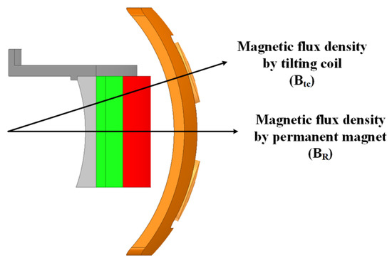
Figure 8.
Principle of generating positioning torque.
The positioning torque is given as follows:
where τp is the positioning torque, k is the coefficient based on the radius of the coil, length of the coil, and permeability, BR is the magnetic flux density of the permanent magnet located in the rotor, and Btc is the magnetic flux density of the tilting coil located in the stator.
The rotor of the spherical multi-DOF actuator with Halbach magnet array is subjected to a force such that the magnetic flux directions of the permanent magnet and coil coincide. The positioning torque is zero and reaches the command position when the two magnetic fluxes coincide. In addition, the positioning torque is zero when the two magnetic flux vectors coincide with each other in a vector in the opposite direction. However, the positioning torque deviates from the command position if an external disturbance is applied.
Figure 9 shows two models to determine the stability of the positioning torque when a coil is placed at one pole (Figure 9a) and when two coils are placed at a pole (Figure 9b).
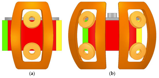
Figure 9.
Two models to determine the stability of the positioning torque: (a) One coil located at a pole; (b) Two coils located at a pole.
The positioning torque characteristics of the selected model are shown in Figure 10 for command angles α = 0°, β = 0° (Figure 10a) and α = 0°, β = 30° (Figure 10b). At the point where α = 0°, the positioning torque exhibits a value of zero and negative slope. Hence, a negative torque is generated if an external disturbance causes a displacement in the positive direction in the vicinity of α = 0°. Additionally, a positive torque is generated if the displacement occurs in the negative direction. Therefore, the spherical multi-DOF actuator with Halbach magnet array can be stably driven based on the command.
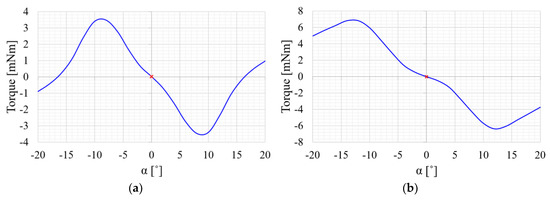
Figure 10.
Positioning torque characteristic when pole pitch angle is 150 °E: (a) α = 0°, β = 0°; (b) α = 0°, β = 30°.
3.4. Control Method
Position control of the multiple DOF actuators is achieved via two non-contact image sensors. As shown in Figure 11a, the two image sensors are arranged with a spatial difference of 90°. Figure 11b shows the values when Sensor 1 is sensing the rotating surface. The two image sensors are spatially 90° apart; thus, the displacements Δy1 and Δy2 are as follows [25]:
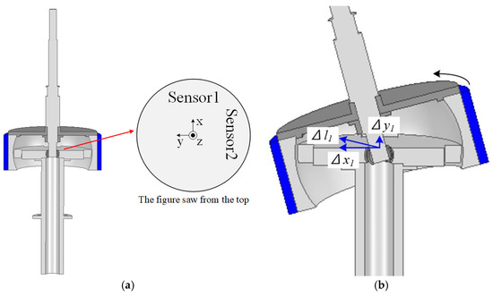
Figure 11.
Image sensor for position control: (a) Position of image sensor; (b) Measured value of Sensor 1.
As shown in Figure 11b, the rotation angle ϕ is as follows:
where r is the distance from the center of the rotor to the measurement surface, and Δl1 is the movement distance about the rotational trajectory measured by Sensor 1.
For achieving position control of the multi-DOF actuator, α and β should be obtained. First, using Equations (12) and (13), β is determined as follows:
Figure 12 shows a state where β = 90°. Additionally, α represents the angle between Δl1 and Δx1. Using Figure 12 and Equation (12), α is derived as follows:
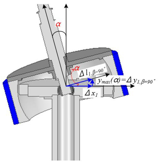
Figure 12.
State of the multi-DOF actuator when β = 90°.
Therefore, position control is achieved by obtaining ϕ, α, and β via the image sensor.
4. Conclusions
In this study, we propose a structure for a dual-airgap slotless-type spherical multi-DOF actuator and examine its power density improvement over a multi-DOF actuator. To improve the output power density of the multi-DOF actuator, a dual-airgap and slotless-type spherical structure was selected to decrease eddy current loss via simultaneous movements of the internal and external rotors. Additionally, a three-phase structure with an induced voltage with a large fundamental wave size and a small harmonic size was selected. Furthermore, a Halbach magnet array was added to existing magnets to increase magnetic flux density of the permanent magnets. We used a detailed design of the winding and rotor magnet structure to finally select a model with high output power density and low torque ripple. Additionally, it is necessary for the multi-DOF actuator to move to the position of the entered command. Therefore, stability analysis is essential to determine whether the actuator moves to the command position. For the actuator to run stably, the torque at the command position must be zero and should exhibit a torque curve with negative slope. If the torque at command position is zero but the torque curve has a positive slope, the actuator deviates from the command position when a slight disturbance is applied. Therefore, stability analysis was performed to confirm whether the spherical multi-DOF actuator with Halbach magnet array was positioned based on the command. Additionally, two image sensors were used for the position control of the multi-DOF actuator. Herein is designed a spherical multi-DOF actuator that improves power density and is located at the desired command position.
Author Contributions
S.C. selected number of phases for the multi-DOF actuator and conducted analysis to improve the power density. H.J.L. has presented the structure of a double air-gap type multi-DOF actuator. J.L. checked and guided the analysis research.
Funding
This research was supported in part by Basic Science Research Program through the National Research Foundation of Korea (NRF) funded by the Ministry of Education, Science and Technology (NRF-2017R1D1A1B03032635) and in part by the Energy Efficiency & Resources of the Korea Institute of Energy Technology Evaluation and Planning (KETEP) grant funded by the Korea government Ministry of Knowledge Economy (No. 2018201010633A).
Conflicts of Interest
The authors declare no conflict of interest.
References
- Palpacelli, M.-C.; Carbonari, L.; Palmieri, G.; Callegari, M. Analysis and design of a reconfigurable 3-DoF parallel manipulator for multimodal tasks. IEEE/ASME Trans. Mechatron. 2014, 20, 1975–1985. [Google Scholar] [CrossRef]
- Cho, S.; Lim, J.-S.; Oh, Y.J.; Jeong, G.; Kang, D.-W.; Lee, J. A Study on Output Characteristics of the Spherical Multi-DOF Motor According to the Number of Phases and Pole Pitch Angles. IEEE Trans. Magn. 2018, 54, 1–5. [Google Scholar] [CrossRef]
- Bhattacharyya, S.; Shimoda, S.; Hayashibe, M. A synergetic brain-machine interfacing paradigm for multi-DOF robot control. IEEE Trans. Syst. Manand Cybern. Syst. 2016, 46, 957–968. [Google Scholar] [CrossRef]
- Ueki, S.; Kawasaki, H.; Ito, S.; Nishimoto, Y.; Abe, M.; Aoki, T.; Ishigure, Y.; Ojika, T.; Mouri, T. Development of a hand-assist robot with multi-degrees-of-freedom for rehabilitation therapy. IEEE/ASME Trans. Mechatron. 2010, 17, 136–146. [Google Scholar] [CrossRef]
- Mori, S.; Tanaka, K.; Nishikawa, S.; Niiyama, R.; Kuniyoshi, Y. High-Speed and Lightweight Humanoid Robot Arm for a Skillful Badminton Robot. IEEE Robot. Autom. Lett. 2018, 3, 1727–1734. [Google Scholar] [CrossRef]
- Lee, H.-J.; Park, H.-J.; Hong, H.-S.; Won, S.-H.; Jin, C.-S.; Lee, B.-S.; Lee, J. An analytic analysis of the multi-degree-of-freedom actuator. IEEE Trans. Magn. 2015, 51, 1–4. [Google Scholar]
- Hong, H.-S.; Won, S.-H.; Lee, H.-W.; Bae, J.-N.; Lee, J. Design of Torque Actuator in Hybrid Multi-DOF System Considering Magnetic Saturation. IEEE Trans. Magn. 2015, 51, 1–4. [Google Scholar] [CrossRef]
- Dehez, B.; Galary, G.; Grenier, D.; Raucent, B. Development of a spherical induction motor with two degrees of freedom. IEEE Trans. Magn. 2006, 42, 2077–2089. [Google Scholar] [CrossRef]
- Yang, X.; Liu, Y.; Chen, W.; Liu, J. Sandwich-type multi-degree-of-freedom ultrasonic motor with hybrid excitation. IEEE Access 2016, 4, 905–913. [Google Scholar] [CrossRef]
- Xia, C.; Xin, J.; Li, H.; Shi, T. Design and analysis of a variable arc permanent magnet array for spherical motor. IEEE Trans. Magn. 2012, 49, 1470–1478. [Google Scholar] [CrossRef]
- Li, Z.; Lun, Q.; Xing, D.; Gao, P. Analysis and implementation of a 3-DOF deflection-type PM motor. IEEE Trans. Magn. 2015, 51, 1–4. [Google Scholar] [CrossRef]
- Rossini, L.; Mingard, S.; Boletis, A.; Forzani, E.; Onillon, E.; Perriard, Y. Rotor design optimization for a reaction sphere actuator. IEEE Trans. Ind. Appl. 2013, 50, 1706–1716. [Google Scholar] [CrossRef]
- Lee, K.-M.; Son, H. Distributed multipole model for design of permanent-magnet-based actuators. IEEE Trans. Magn. 2007, 43, 3904–3913. [Google Scholar] [CrossRef]
- Takahara, K.; Hirata, K.; Niguchi, N.; Nishiura, Y.; Sakaidani, Y. Experimental evaluation of the static characteristics of multi-degree-of-freedom spherical actuators. IEEE Trans. Magn. 2017, 53, 1–5. [Google Scholar]
- Tsukano, M.; Sakaidani, Y.; Hirata, K.; Niguchi, N.; Maeda, S.; Zaini, A. Analysis of 2-degree of freedom outer rotor spherical actuator employing 3-D finite element method. IEEE Trans. Magn. 2013, 49, 2233–2236. [Google Scholar] [CrossRef]
- Sugimoto, H.; Kamiya, K.; Nakamura, R.; Asama, J.; Chiba, A.; Fukao, T. Design and basic characteristics of multi-consequent-pole bearingless motor with bi-tooth main poles. IEEE Trans. Magn. 2009, 45, 2791–2794. [Google Scholar] [CrossRef]
- Bai, K.; Lee, K.-M. Direct field-feedback control of a ball-joint-like permanent-magnet spherical motor. IEEE/ASME Trans. Mechatron. 2013, 19, 975–986. [Google Scholar] [CrossRef]
- Maeda, S.; Hirata, K.; Niguchi, N. Dynamic analysis of an independently controllable electromagnetic spherical actuator. IEEE Trans. Magn. 2013, 49, 2263–2266. [Google Scholar] [CrossRef]
- Son, H.; Lee, K.-M. Open-loop controller design and dynamic characteristics of a spherical wheel motor. IEEE Trans. Ind. Electron. 2010, 57, 3475–3482. [Google Scholar] [CrossRef]
- Aoyagi, M.; Beeby, S.P.; White, N.M. A novel multi-degree-of-freedom thick-film ultrasonic motor. IEEE Trans. Ultrason. Ferroelectr. Freq. Control 2002, 49, 151–158. [Google Scholar] [CrossRef]
- Takemura, K.; Ohno, Y.; Maeno, T. Design of a plate type multi-DOF ultrasonic motor and its self-oscillation driving circuit. IEEE/ASME Trans. Mechatron. 2004, 9, 474–480. [Google Scholar] [CrossRef]
- Kawano, H.; Ando, H.; Hirahara, T.; Yun, C.; Ueha, S. Application of a multi-DOF ultrasonic servomotor in an auditory tele-existence robot. IEEE Trans. Robot. 2005, 21, 790–800. [Google Scholar] [CrossRef]
- Li, H.; Xia, C.; Shi, T. Spherical harmonic analysis of a novel Halbach array PM spherical motor. In Proceedings of the 2007 IEEE International Conference on Robotics and Biomimetics, Sanya, China, 15–18 December 2007; pp. 2085–2089. [Google Scholar]
- Li, H.F.; Xia, C.L.; Song, P. Magnetic field analysis of a Halbach array PM spherical motor. In Proceedings of the 2007 IEEE International Conference on Automation and Logistics, Jinan, China, 18–21 August 2007; pp. 2019–2023. [Google Scholar]
- Oh, Y.-J.; Lee, W.-K.; Lee, H.-J.; Kang, D.-W.; Won, S.-H.; Lee, J. Position Estimation for the Permanent Magnet Spherical Motor using Optical Image Sensor. In Korean Institute of Electrical Engineers Summer Conference; The Korean Institute of Electrical Engineers: Seoul, Korea, 2011; pp. 943–944. [Google Scholar]
© 2019 by the authors. Licensee MDPI, Basel, Switzerland. This article is an open access article distributed under the terms and conditions of the Creative Commons Attribution (CC BY) license (http://creativecommons.org/licenses/by/4.0/).