Article

Reactive Power Compensation and Imbalance Suppression by Star-Connected Buck-Type D-CAP

1
China-EU Institute for Clean and Renewable Energy, Huazhong University of Science and Technology, Wuhan 430074, China
2
State Key Laboratory of Advanced Electromagnetic Engineering and Technology, School of Electrical and Electronic Engineering, Huazhong University of Science and Technology, Wuhan 430074, China
3
Wuhan National Laboratory for Optoelectronics, Huazhong Institute of Electro-optics, Wuhan 430223, China
4
Department of Electrical, Computer and System Engineering, Rensselaer Polytechnic Institute, Troy, NY 12180, USA
*
Author to whom correspondence should be addressed.
Energies 2019, 12(10), 1914; https://doi.org/10.3390/en12101914
Submission received: 5 March 2019 / Revised: 10 May 2019 / Accepted: 16 May 2019 / Published: 18 May 2019
(This article belongs to the Special Issue HVDC/FACTS for Grid Services in Electric Power Systems)

Abstract

:
Reactive power and negative-sequence current generated by inductive unbalanced load will not only increase line loss, but also cause the malfunction of relay protection devices triggered by a negative-sequence component in the power grid, which threatens the safe operation of the power system, so it is particularly important to compensate reactive power and suppress load imbalance. In this paper, reactive power compensation and imbalance suppression by a three-phase star-connected Buck-type dynamic capacitor (D-CAP) under an inductive unbalanced load are studied. Firstly, the relationship between power factor correction and imbalance suppression in a three-phase three-wire system is discussed, and the principle of D-CAP suppressing load imbalance is analyzed. Next, its compensation ability for negative-sequence currents is determined, which contains theoretical and actual compensation ability. Then an improved control strategy to compensate reactive power and suppress imbalance is proposed. If the load is slightly unbalanced, the D-CAP can completely compensate the reactive power and negative-sequence currents. If the load is heavily unbalanced, the D-CAP can only compensate the positive-sequence reactive power and a part of the negative-sequence currents due to the limit of compensation ability. Finally, a 33 kVar/220 V D-CAP prototype is built and experimental results verify the theoretical analysis and control strategy.

1. Introduction

There are a large number of inductive unbalanced loads in three-phase three-wire power systems generating reactive power and negative-sequence current, which not only increase line loss, but also cause malfunctions in overload protection devices triggered by negative-sequence current, thus threatening the safe operation of the power system. It is particularly important to compensate reactive power and negative-sequence current [1,2].
Reactive power compensation is an important means to improve power quality. Shunt power capacitors and shunt reactors have been widely used in power grid [3], but they can only provide constant reactive power. Different from fixed capacitors, static Var compensator (SVC) has advantages of adjustable reactive power and rapid response speed. Elements which may be used to make SVC typically include thyristor-controlled reactor (TCR) and thyristor-switched capacitor (TSC). In [4,5], two kinds of reactive power compensation schemes along with harmonic reduction techniques for unbalanced loads are addressed. Although with novel solutions, harmonic problems produced by TCR obtain some improvement, while high energy loss and large volume further limit its development.
Compared with SVC, the static synchronous compensator (STATCOM) has higher compensation accuracy, faster regulation speed, stronger compensation ability, and lower harmonic content based on a fully-controllable power semiconductor device and high switching frequency [6]. Two control strategies for star-connected and delta-connected STATCOMs under an unbalanced load are proposed in [7,8]. However, the ability of a STATCOM compensating negative-sequence current is affected by its structure. In [9], the compensation ability of STATCOM with star and delta configurations is indicated and analyzed. The third-harmonic injection method proposed in [10] achieves a significant improvement in STATCOM ability of simultaneous compensation for reactive and negative-sequence current. Considering unbalanced grid voltages, an improved regulation scheme with positive and negative sequence control for modular multilevel converter (MMC) in medium-voltage distribution static synchronous compensator (DSTATCOM) application is proposed in [11].
Although the compensation characteristic of a STATCOM for reactive and negative-sequence currents is good, it is complicated to stabilize and balance DC-link electrolytic capacitors’ voltages, which will influence the reliability of STATCOMs [12,13]. Additionally, the high cost of STATCOMs affect their application in low-power applications. Although a matrix converter can be designed as a dynamic compensator without the bulky electrolytic capacitors, large numbers of bi-directional switches have to be used [14,15].
In [16,17,18], a magnetic energy recovery switch (MERS) is applied in reactive power compensation due to its characteristic equivalent to a variable capacitor. However, it will produce some harmonics because it adopts a phase-shifting control method. Additionally, electrolytic capacitor voltage fluctuation will further increase the harmonic contents of the output current. Similar to MERS, another VAr generator is analyzed in [19,20], which can be equivalent to a variable capacitor with a H-bridge inverter and DC capacitance. The same as with STATCOMs, the voltage fluctuation of the electrolytic capacitor on the DC side will affect their reliability.
Considering a large number of fixed capacitors in a distribution system, it is economical if power electronic technology can be used to reconstruct them to achieve better performance. Compared with the above compensators, the dynamic capacitor (D-CAP) is a simple, reliable, and economical solution without bulky electrolytic capacitors, which is composed of a power capacitor and a thin AC converter (TACC) [21,22,23]. Furthermore, the TACC could be configured with a simple topology, such as a Buck, Boost, or a Buck-Boost circuit, so the D-CAP has great potential to be used in low-power applications. Extending cells with a series connection, it is also feasible for the D-CAP to be applied in high-voltage applications [24]. Considering harmonic contents in the grid voltage, the output currents of the D-CAP will contain some distortions due to the impacts of self-resonance and on-state voltage drop of the switches. In order to reduce the harmonic content of the output currents, a waveform shaping strategy and a resonance damping method are proposed in [25,26], respectively.
Although reactive power compensation has got some focus for D-CAP, load imbalance suppression has not been discussed. Since the D-CAP is equivalent to a capacitor controlled by the duty ratio, it is meaningful to study how to suppress the load imbalance by capacitors. Reference [27] shows that only adopting capacitors cannot compensate for all unbalanced load, but it does not specify its compensation range. Using a delta-connected D-CAP to compensate the unbalanced load has been studied in the author’s previous article [28]. Although the voltage in each phase is the same for a delta-connected D-CAP without the potential deviation at the neutral point, the line voltage of the delta structure is larger than the phase voltage of the star structure. For a star-connected D-CAP, the operating voltage of the switching device is lower than a delta-connected D-CAP, and the number of cascaded units is less, especially in high-voltage applications [24]. Due to the cost advantages, it is also of great significance to study star-connected D-CAPs. In this paper, reactive power compensation and imbalance suppression for a three-phase star-connected Buck-type D-CAP are explored.
The innovations of this paper can be described as follows: In Section 2, the relationship between power factor correction and load imbalance suppression in three-phase three-wire system is analyzed. In Section 3, the theoretical compensation ability of the D-CAP for negative-sequence current is derived. Considering that the rated voltage of the D-CAP is limited, the actual compensation ability of the D-CAP is also analyzed. In Section 4, an improved control strategy is proposed, which can make the D-CAP compensate negative-sequence current the best. Finally, experimental results verify the correctness of the theoretical analysis and the effectiveness of the control strategy.

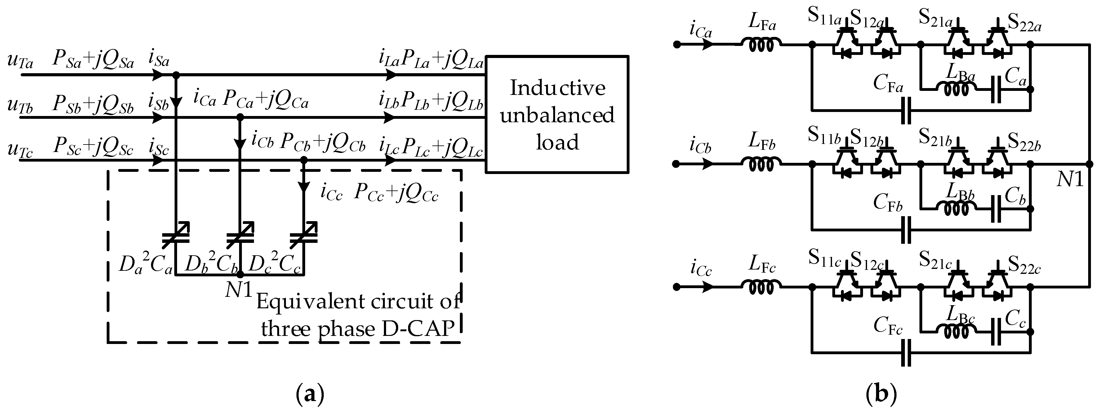
2. Principle of the D-CAP Compensating for Reactive Power and Suppressing the Load Imbalance

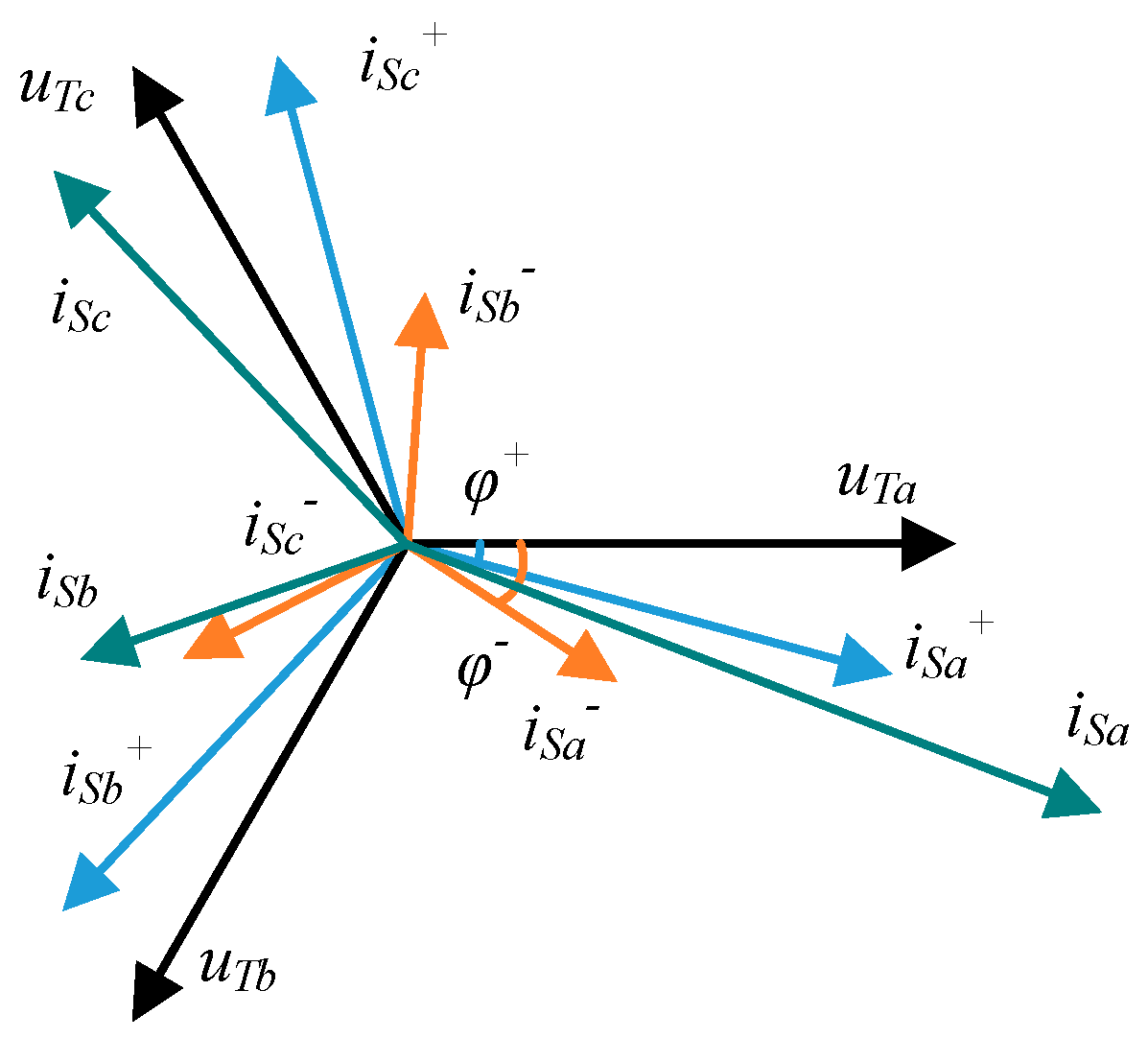
2.1. Relationship between Power Factor Correction and Imbalance Suppression

For the system of a three-phase star-connected Buck-type D-CAP and inductive unbalanced load, shown in Figure 1, in order to simplify the analysis, only fundamental components are considered. The load is linear and the three-phase voltages on the grid side [uTa uTb uTc] are balanced and symmetrical, where:
{ u T a = U m sin ( ω t ) u T b = U m sin ( ω t 120 ) u T c = U m sin ( ω t + 120 )
As shown in Figure 2, according to the symmetric component method, the three-phase grid side currents [iSa iSb iSc] can be decomposed into positive-sequence components [ i S a + i S b + i S c + ] and negative-sequence components [ i S a i S b i S c ], where:
{ i S a = i S a + + i S a i S a + = I S m + sin ( ω t φ + ) i S a = I S m sin ( ω t φ )
Reactive power QSa of phase A can be decomposed into reactive power generated by i S a + acting on uTa and reactive power generated by i S a acting on uTa. Similarly, QSb and QSc can be decomposed in this way. Reactive power at the grid side can be expressed as:
{ Q S a = U m ( I S m + sin φ + + I S m sin φ ) / 2 Q S b = U m [ I S m + sin φ + + I S m sin ( 120 + φ ) ] / 2 Q S c = U m [ I S m + sin φ + I S m sin ( 120 φ ) ] / 2
In Equation (3), φ+ is the phase angle of i S a + lagging behind uTa, φ is the phase angle of i S a lagging behind uTa. If power factors of phases A, B, and C on the grid side are 1 under the effects of the D-CAP, which means QSa = 0, QSb = 0, QSc = 0, then:
{ I S m + sin φ + = 0 I S m = 0
Equation (4) shows that both positive-sequence reactive components and negative-sequence components of the three-phase grid side currents are 0 at this time, and only positive-sequence active components are left at the grid side.
Consequently, in three-phase three-wire system with unbalanced load, if three-phase power factors at the grid side are equal to 1 under the effects of the D-CAP, then the D-CAP can compensate the reactive power and suppress load imbalance.

2.2. Principle of the D-CAP Suppressing the Load Imbalance

The D-CAP is equivalent to the capacitance of D k 2 Ck under the control of the constant duty ratio [21,22]. Considering that the neutral potential drift of the star-connected D-CAP will bring more complexity and trouble to the analysis, the equivalent capacitance of the D-CAP can be transformed into delta-connected capacitors, shown in Figure 3a, if delta-connected capacitors meet Equation (5):
{ C a b = D a 2 D b 2 C a C b / ( D a 2 C a + D b 2 C b + D c 2 C c ) C b c = D b 2 D c 2 C b C c / ( D a 2 C a + D b 2 C b + D c 2 C c ) C c a = D c 2 D a 2 C c C a / ( D a 2 C a + D b 2 C b + D c 2 C c )
Shown in Figure 3b, iCab can be decomposed into active component i C a b p parallel with uTa, and reactive component i C a b q , perpendicular to uTa. Similarly, iCac can be decomposed into i C a c p and i C a c q . Then the reactive and active components of iCa can be expressed with i C a b q + i C a c q and i C a b p + i C a c p . Similarly, iCb and iCc also contain active and reactive components. The total active power absorbed by the three-phase D-CAP is 0, which provides feasibility for the D-CAP to suppress load imbalance by transferring active power and compensating reactive power if the duty ratio can be controlled reasonably.
From Figure 3b, reactive powers absorbed by the D-CAP can be calculated:
{ Q C a = 3 U m 2 ω ( C a b + C c a ) / 4 Q C b = 3 U m 2 ω ( C a b + C b c ) / 4 Q C c = 3 U m 2 ω ( C c a + C b c ) / 4
Supposing iLa can be decomposed into the positive-sequence component i L a + and negative-sequence component i L a :
{ i L a = i L a + + i L a i L a + = I L m + sin ( ω t θ + ) i L a = I L m sin ( ω t θ )
In Equation (7), θ+ is the phase angle of i L a + lagging behind uTa, and θ is the phase angle of i L a lagging behind uTa. Three-phase reactive powers at the grid side after the D-CAP put into operation can be deduced:
{ Q S a = Q C a + Q L a = U m ( I L m + sin θ + + I L m sin θ ) / 2 3 U m 2 ω ( C a b + C c a ) / 4 Q S b = Q C b + Q L b = U m [ I L m + sin θ + + I L m sin ( 120 + θ ) ] / 2 3 U m 2 ω ( C a b + C b c ) / 4 Q S c = Q C c + Q L c = U m [ I L m + sin θ + I L m sin ( 120 θ ) ] / 2 3 U m 2 ω ( C c a + C b c ) / 4
Assuming QSa = 0, QSb = 0 and QSc = 0, then:
{ C a b = [ I L m + sin θ + + 2 I L m sin ( 120 θ ) ] / ( 3 ω U m ) C b c = ( I L m + sin θ + 2 I L m sin θ ) / ( 3 ω U m ) C c a = [ I L m + sin θ + 2 I L m sin ( 120 + θ ) ] / ( 3 ω U m )
If three-phase equivalent capacitances of the D-CAP meet Equation (9), the power factors of the three-phase grid side will be corrected to 1. According to the relationship between power factor correction and imbalance suppression in Section 2.1, reactive power will be compensated and load imbalance will be suppressed absolutely.

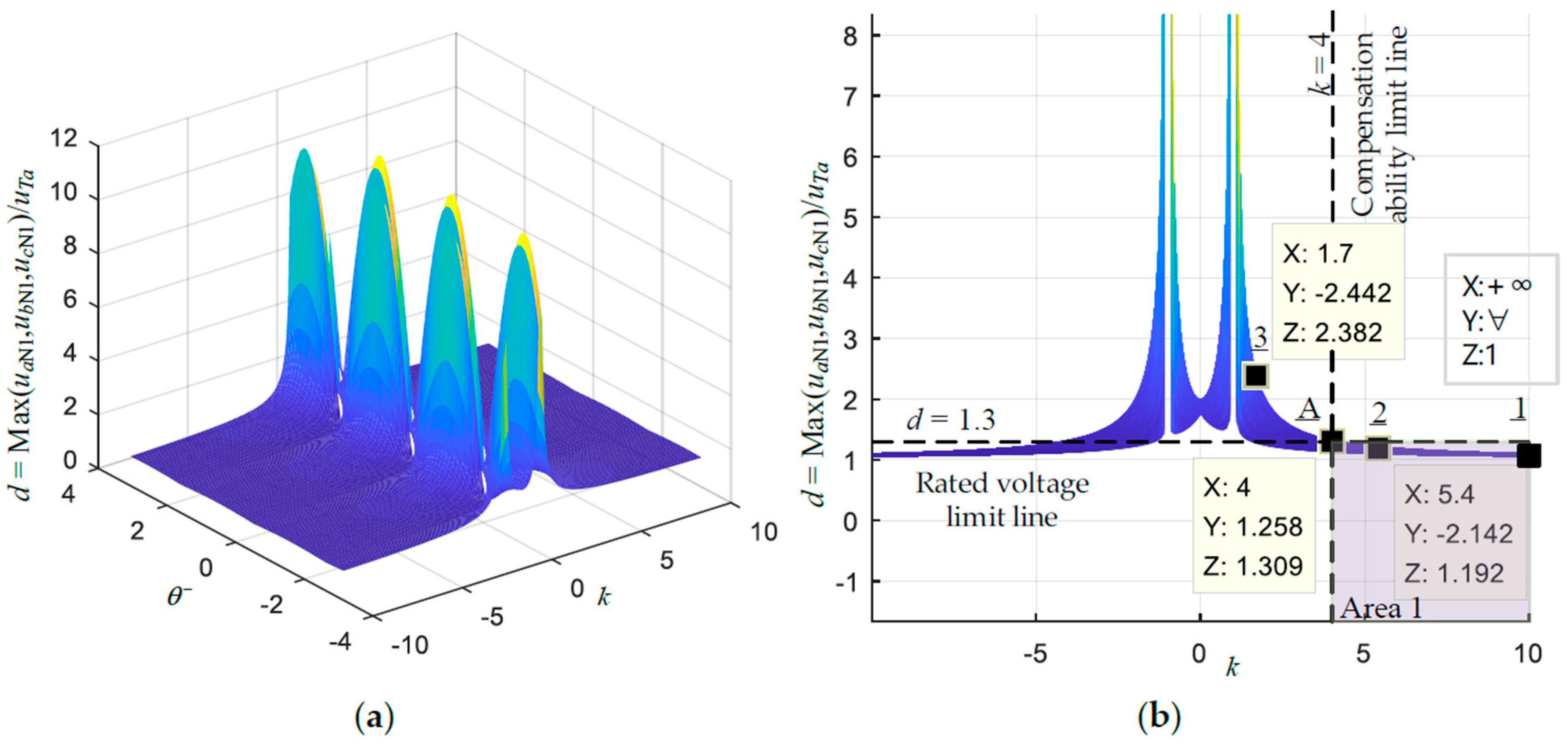
3. Compensation Ability of a Star-Connected D-CAP for Negative-Sequence Currents

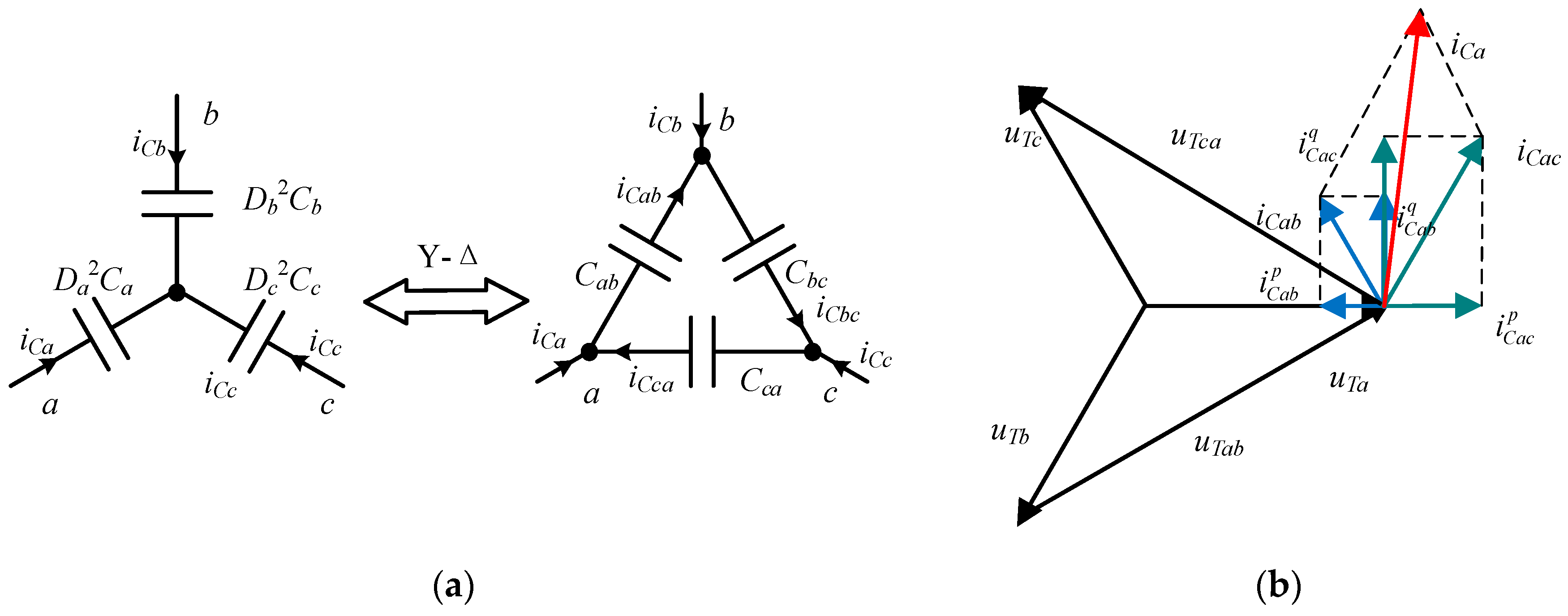
3.1. Theoretical Compensation Ability of a Star-Connected D-CAP

In Equation (9), we can find I L m + sinθ+ is the positive-sequence reactive component amplitude of the load currents, and I L m sinθ, I L m sin(120° + θ), − I L m sin(120° − θ) are the negative-sequence reactive components amplitude of the load currents. For example, under some load conditions, the positive-sequence reactive components’ amplitude is smaller than two times of negative-sequence reactive components amplitude. Then the value of Cbc is negative according to Equation (9), which is unachievable for the D-CAP. Therefore, the compensation ability of the D-CAP is limited.
Take phase A as another example shown in Figure 4. Draw vertical line relative to uTa from the end point of i L a + and dividing line 1 parallel to uTa at the midpoint of vertical line. The value of Cab is positive if i L a is in the zone 1 which is above dividing line 1. Similarly, the values of Cca and Cbc are positive if i L b and i L c are in zone 2 and zone 3, respectively. Considering that i L a , i L b , and i L c are symmetrical, the value of Cab, Cbc, and Cca are all greater than 0 if and only if i L a , i L b , and i L c are all in the ΔRST.
Consequently, in the three-phase three-wire system, if the negative-sequence components of the load currents are located in the ΔRST, shown in Figure 4, meaning the value of equivalent capacitances calculated by Equation (9) are positive, the D-CAP can completely compensate the reactive power and suppress the load imbalance. Otherwise, the D-CAP can only compensate the positive-sequence reactive components and a part of the negative-sequence components of the load currents lying in the scope of ΔRST.
Additionally, the circle with radius i L q + /4 in Figure 4 refers to the actual compensation ability of the D-CAP, which will be illustrated in Section 3.2.

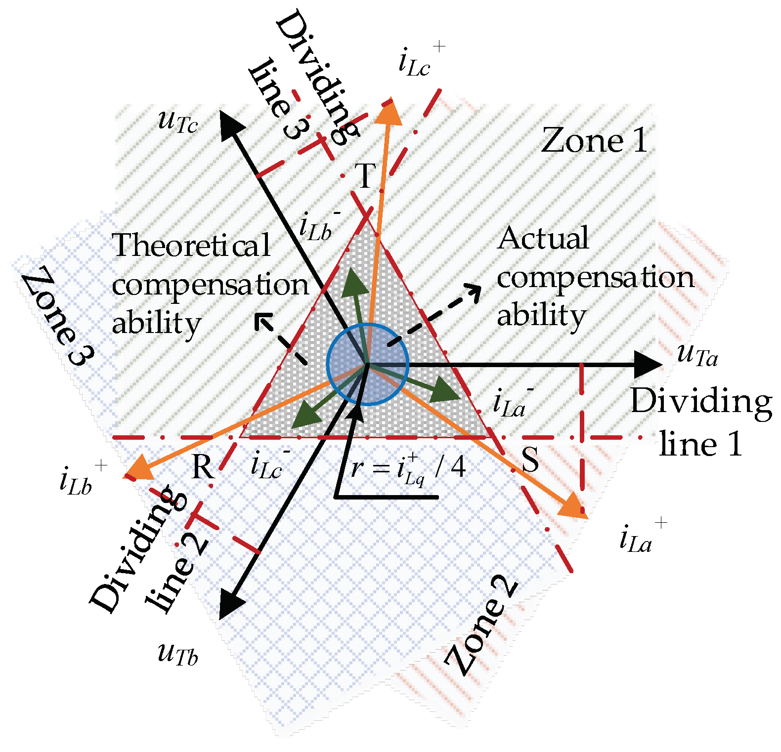
3.2. Actual Compensation Ability of a Star-Connected D-CAP

Deviation of potential at the neutral point will occur when the star-connected D-CAP suppresses the load imbalance, which will make one of the voltages between the grid side and the D-CAP neutral point higher. In practice, the rated voltage of each phase D-CAP is generally 1.1–1.3 times higher than the grid voltage in order to maintain a safety margin, so the actual compensation ability of the D-CAP under an unbalanced load will be limited by the rated voltage.
Shown in Figure 5, the coordinate expressions of three phase grid voltages are:
{ U ˙ T a = ( U m , 0 ) U ˙ T b = ( U m / 2 , 3 U m / 2 ) U ˙ T c = ( U m / 2 , 3 U m / 2 )
In order to compensate reactive power and negative-sequence currents, the coordinate expressions of [iCa iCb iCc] can be described as:
{ I ˙ C a = ( I L m cos θ , I L m sin θ ) + ( 0 , I L m + sin θ + ) I ˙ C b = [ I L m cos ( 120 θ ) , I L m sin ( 120 θ ) ] + [ 3 ( I L m + sin θ + ) / 2 , I L m + sin θ + / 2 ] I ˙ C c = [ I L m cos ( 120 + θ ) , I L m sin ( 120 + θ ) ] + [ 3 ( I L m + sin θ + ) / 2 , I L m + sin θ + / 2 ]
If the coordinate of the D-CAP neutral point potential is (x, y), then:
{ [ ( U m , 0 ) ( x , y ) ] I ˙ C a [ ( U m / 2 , 3 U m / 2 ) ( x , y ) ] I ˙ C b [ ( U m / 2 , 3 U m / 2 ) ( x , y ) ] I ˙ C c
According to the mathematical condition that two phasors are mutually orthogonal, it can be solved:
{ x = U m [ 1 k sin θ 2 ( sin θ ) 2 ] / ( 1 k 2 ) y = U m cos θ ( 2 sin θ + k ) / ( 1 k 2 ) k I L m + sin θ + / I L m
Therefore, if the D-CAP can absolutely compensate the reactive power and negative-sequence currents of the load, the neutral point potential of the D-CAP will be affected by the phase angle θ and the reactive/imbalance index k, where k is the ratio of the positive-sequence reactive components’ amplitude I L m + sinθ+ to the negative-sequence components amplitude I L m .
With the coordinate of uT and N1, the amplitudes of [uaN1 ubN1 ucN1] can be calculated. Here, drift factor d is introduced and defined as max(uaN1 ubN1 ucN1)/uTa. Figure 6 presents the relationship between drift factor d and reactive/imbalance index k, θ. Because the rated voltage of the D-CAP is generally 1.1–1.3 times as high as the grid voltage, the ratio of positive-sequence reactive components amplitude to negative-sequence components amplitude of the D-CAP compensation currents is limited. In Figure 6b, we can find if reactive/imbalance index k is greater than 4, the effect of θ to drift factor d is small. To simplify analysis and make the voltages at both ends of the D-CAP not exceed the rated voltage, θ is assumed to be kept at a value producing the maximal potential deviation at the neutral point. Therefore, for D-CAP currents, the positive-sequence reactive components’ amplitude should be greater than four times the negative-sequence components amplitude to ensure the voltages at both ends of the D-CAP do not exceed its rated voltage.
As shown in Figure 6b, Point A is the intersection of the rated voltage limit line (d = 1.3) and the compensation ability limit line (k = 4). Area 1 is below the rated voltage limit line (d = 1.3) and on the right of the compensation ability limit line (k = 4). Here, area 1 is equivalent to the circle whose radius is i L q + /4 in Figure 4. If the negative-sequence components of the load currents are in the scope of the circle, that means θ and the reactive/imbalance index k are in area 1, and D-CAP can compensate the reactive power and suppress the load imbalance without exceeding the rated voltage limit.

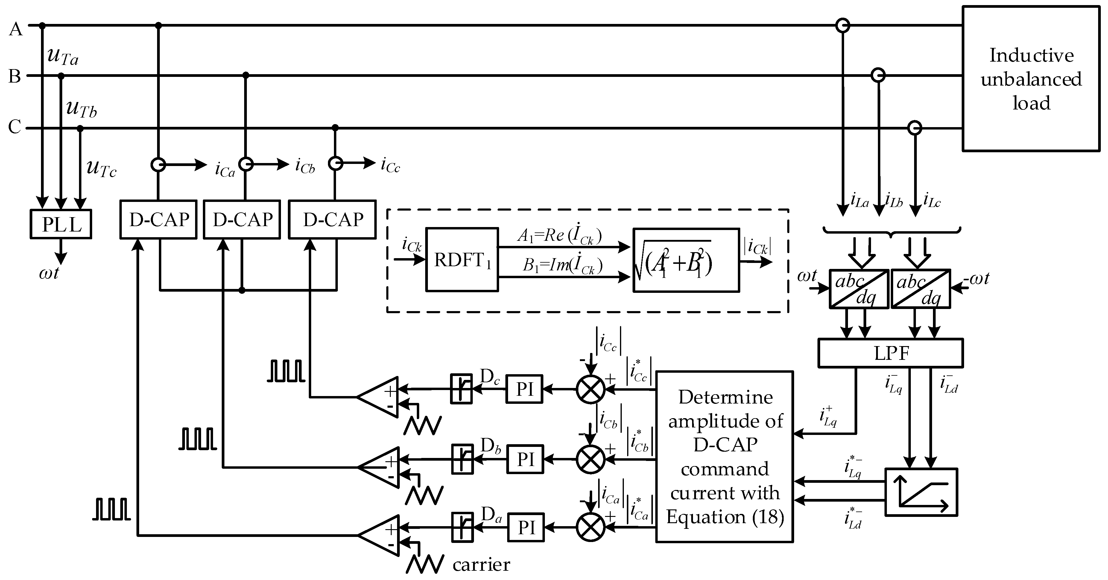
4. Proposed Control Strategy of the D-CAP to Compensate the Reactive Power and Suppress Load Imbalance

For the three-phase star-connected Buck-type D-CAP, the proposed control strategy to compensate the reactive power and suppress load imbalance is shown in Figure 7.
Firstly, we transform the load currents [iLa iLb iLc] with Equations (14) and (15), respectively. Then passing through a low-pass filter, the positive-sequence active and reactive components [ i L d + i L q + ], and negative-sequence active and reactive components [ i L d i L q ] are obtained:
( i L d + i L q + ) = 2 / 3 ( sin ω t sin ( ω t 120 ) sin ( ω t + 120 ) cos ω t cos ( ω t 120 ) cos ( ω t + 120 ) ) ( I L m + sin ( ω t φ + ) I L m + sin ( ω t φ + 120 ) I L m + sin ( ω t φ + + 120 ) ) = ( I L m + cos φ + I L m + sin φ + )
( i L d i L q ) = 2 / 3 ( sin ( ω t ) sin ( ω t + 120 ) sin ( ω t 120 ) cos ( ω t ) cos ( ω t + 120 ) cos ( ω t 120 ) ) ( I L m sin ( ω t φ ) I L m sin ( ω t φ + 120 ) I L m sin ( ω t φ 120 ) ) = ( I L m cos φ I L m sin φ )
Since the actual compensation ability of the D-CAP for negative-sequence currents is limited by its rated voltage, it is necessary to add an amplitude limit on the negative-sequence currents. The processing method of the negative sequence currents is derived as follows:
i L q * = { i L q ,           i f   k ( i L d ) 2 + ( i L q ) 2 < i L q + i L q i L q + / [ k ( i L d ) 2 + ( i L q ) 2 ] ,   i f   k ( i L d ) 2 + ( i L q ) 2 > i L q +
i L d * = { i L d ,           i f   k ( i L d ) 2 + ( i L q ) 2 < i L q + i L d i L q + / [ k ( i L d ) 2 + ( i L q ) 2 ] ,   i f   k ( i L d ) 2 + ( i L q ) 2 > i L q +
If the D-CAP can compensate the reactive power and negative-sequence currents to the utmost, the amplitudes of [iCa iCb iCc] are uniquely determined. Command current amplitudes of the D-CAP can be obtained with i L q * + , i L d * , and i L q * as follows:
{ | i C a * | = ( i L d * ) 2 + ( i L q + + i L q * ) 2 | i C b * | = ( i L d * / 2 3 i L q * / 2 ) 2 + ( 3 i L d * / 2 i L q * / 2 + i L q + ) 2 | i C c * | = ( i L d * / 2 + 3 i L q * / 2 ) 2 + ( 3 i L d * / 2 i L q * / 2 + i L q + ) 2
We compare the command currents amplitudes calculated by Equation (18) with the actual current amplitudes of [iCa iCb iCc], which can be extracted and calculated with the RDFT method [29]. Then we regulate the error through a PI controller to control the duty ratio of the D-CAP. Finally, the switches of the Buck-type AC-AC converter are driven through the modulated output signal. By adjusting the duty ratio, the positive-sequence reactive power and negative-sequence currents of the load can be effectively compensated.

5. Experiment Verification

In order to verify the effectiveness of the control strategy, experimental tests with a 33 kVar/220 V three-phase Buck-type D-CAP are carried out. Figure 1b shows the system configuration. The D-CAP parameters are given in Table 1, which can be determined by the methods in [30]. The experimental prototype is shown in Figure 8. In the front view of Figure 8a, the three-phase main circuits of the prototype are divided into three layers, where the A-phase, B-phase, and C-phase circuits are arranged from the top to the bottom layers, respectively. The A-phase circuit is shown in the top view of Figure 8b.
Experiments are implemented with three different cases in which the load is star-connected with the resistor and inductor in series, as shown as Table 2. Case 1 is implemented under a balanced load, which only needs reactive power compensation. Case 2 is used to verify the feasibility of the D-CAP to compensate the negative-sequence currents, so an unbalanced load is adopted, which corresponds to a reactive/imbalance index k > 4. To verify the compensation ability of the D-CAP, Case 3 is operated under a heavily unbalanced load, whose negative-sequence currents are beyond the compensation ability of the D-CAP, which corresponds to a reactive/imbalance index k < 4. Only the inductive part of the load is unbalanced in this experiment; it is also effective for the proposed control strategy if the resistive part is unbalanced even if both of the resistive and inductive parts are unbalanced.

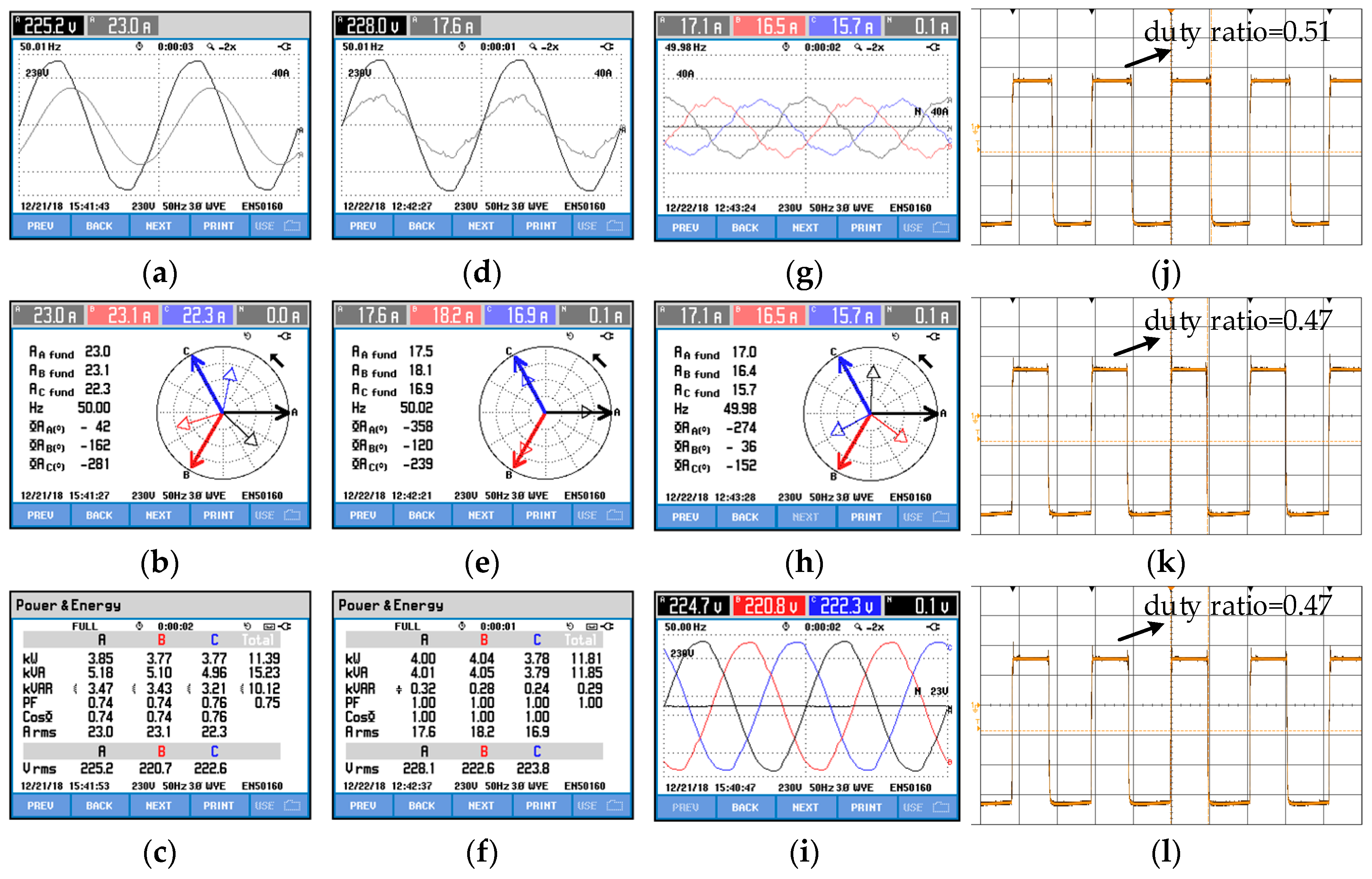
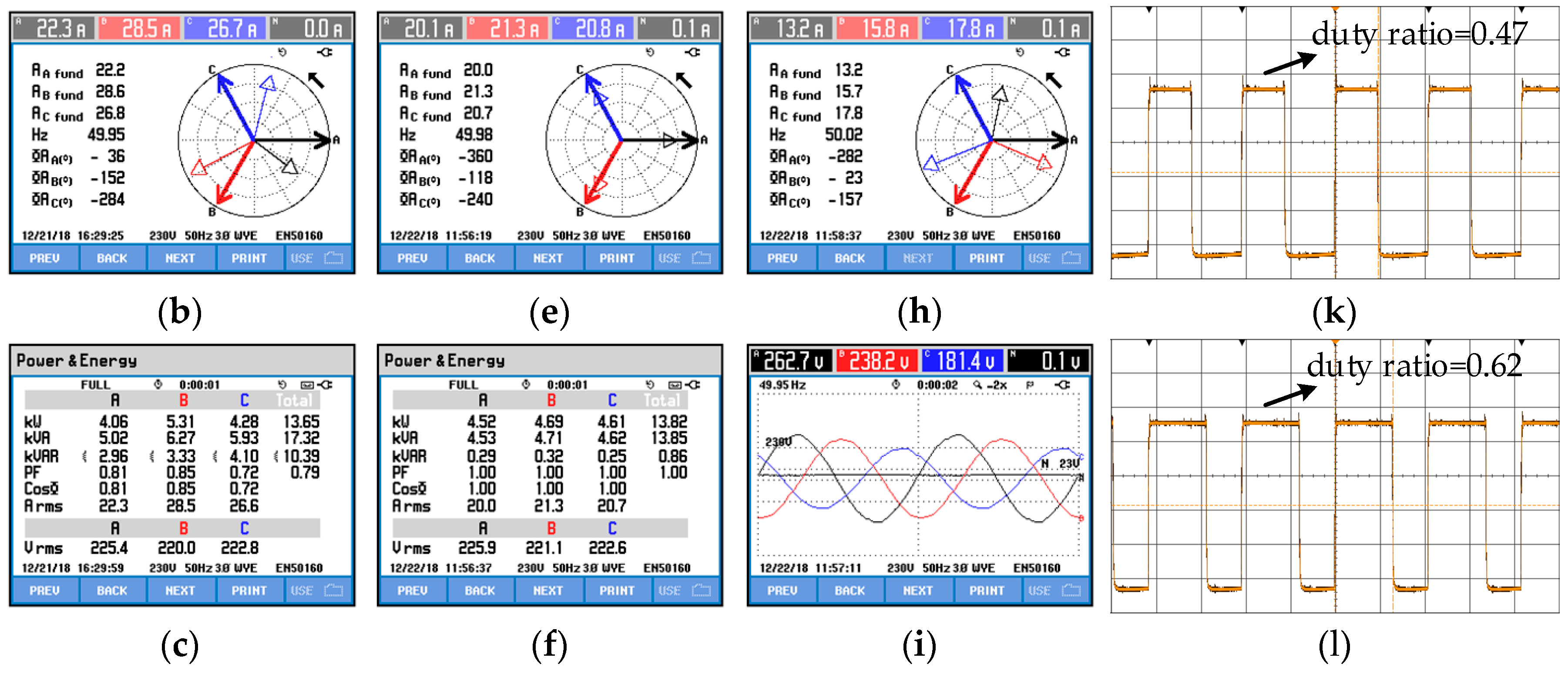
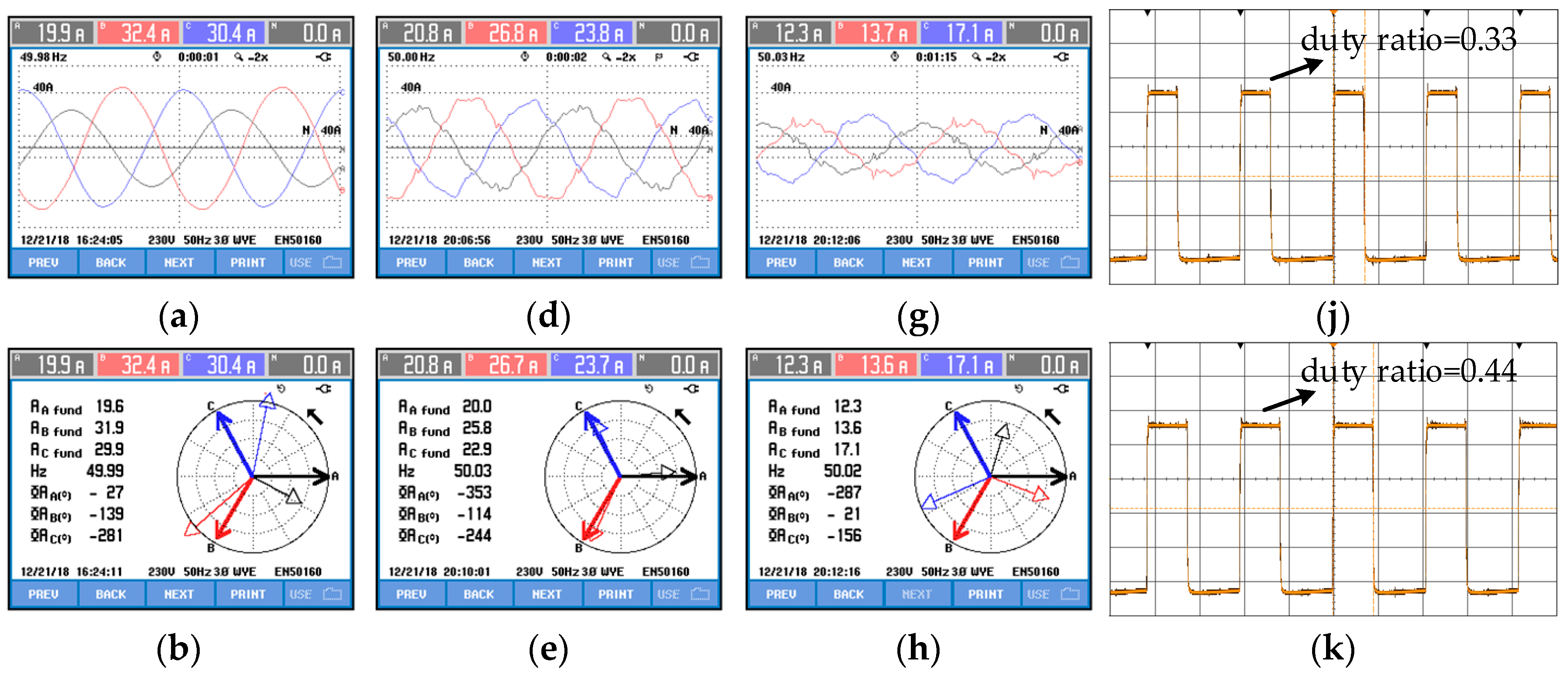
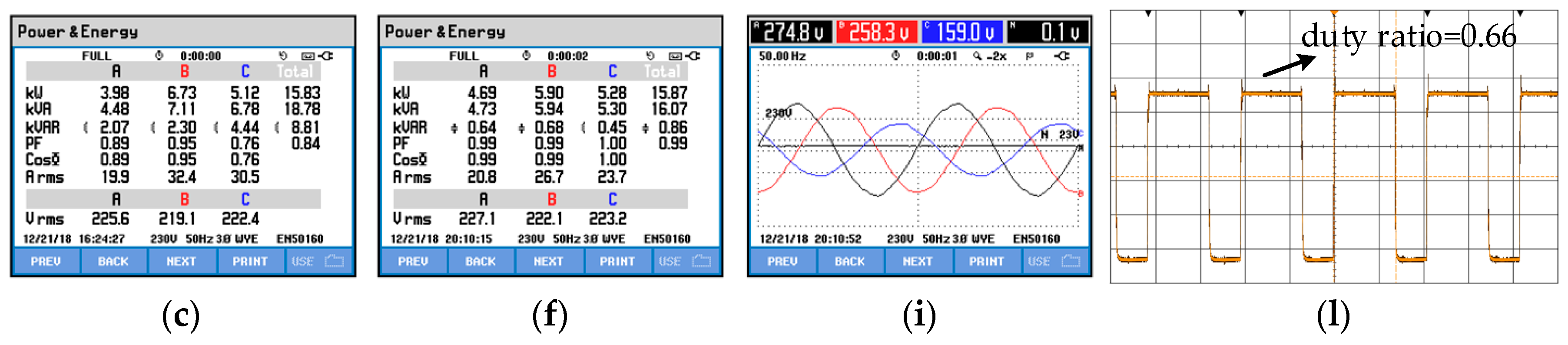
5.1. Case 1: D-CAP for Inductive Balanced Load

Only reactive power is needed if the load is inductive and balanced. Shown in Figure 9a,b, currents at the load side can be considered balanced with values 23.0 A, 23.2 A, and 22.3 A, respectively and lag behind grid voltages. Figure 9c shows the three-phase power factors are 0.74, 0.74, and 0.76. In this case, the reactive/imbalance index k is toward positive infinity, represented as Point 1 in Figure 6b. When the D-CAP is used to compensate the reactive power with the proposed control strategy, shown in Figure 7, the phase angle of the currents and voltages at the grid side become the same (Figure 9d,e) and the three-phase power factors are regulated to 1 (Figure 9f). In Figure 9h, the D-CAP currents’ lead voltages by 86°, but not 90°, because of active power loss when the D-CAP operates. The three-phase duty ratios of the D-CAP are 0.51, 0.47, and 0.47, respectively. Therefore, the reactive power compensation can be achieved under the effects of the D-CAP if the load is balanced and inductive.

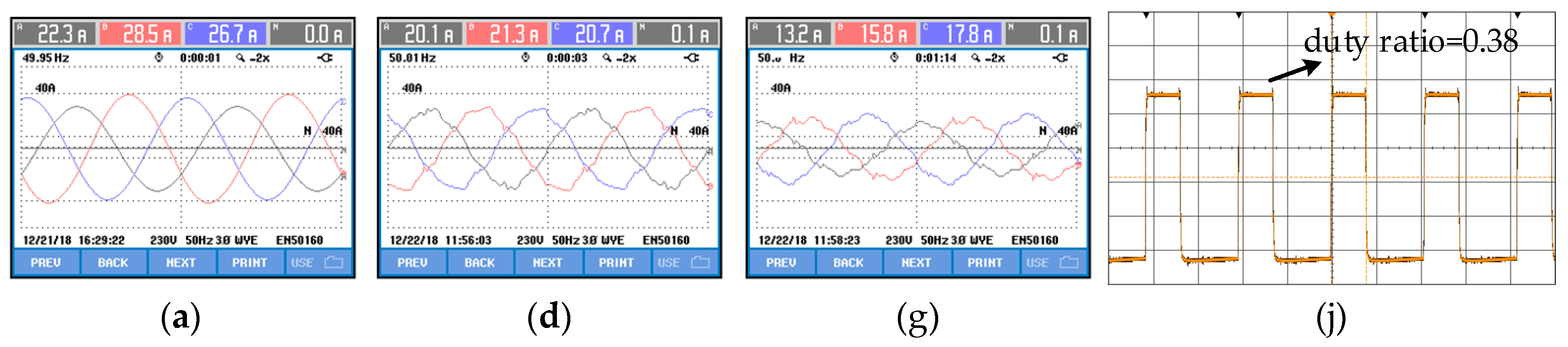
5.2. Case 2: D-CAP for Slightly Unbalanced Inductive Load

Comprehensive control of reactive power compensation and imbalance suppression are implemented under a slightly unbalanced load in this case. Calculated by Equation (13), the reactive/imbalance index k is equal to 5.4, which corresponds to Point 2 in Figure 6b. Shown in Figure 10, currents at the grid side are unbalanced (Figure 10a) and lag behind grid voltages (Figure 10b) when the D-CAP is not put into operation with power factors 0.81, 0.85, and 0.72, respectively (Figure 10c). Currents at the grid side become balanced (Figure 10d,e) and the three-phase power factors are regulated to 1 (Figure 10f) after the D-CAP is put into operation. The three-phase equivalent capacitances can be regulated properly under different duty ratios, whose values are, respectively, 0.38, 0.47, and 0.62. In the Figure 10g,h, the output currents of the D-CAP are unbalanced due to different equivalent capacitances. Since the negative-sequence components’ amplitude is smaller than one quarter of the positive-sequence reactive components’ amplitude in this case, which is not constrained by the negative-sequence components’ amplitude limit shown in Equations (16) and (17), the greatest voltage at both ends of the three-phase D-CAP is 262.7 V in Figure 10i.

5.3. Case 3: D-CAP for Heavily Unbalanced Inductive Load

This case is implemented under a heavily unbalanced load. Calculated by Equation (13), the reactive/imbalance index k is equal to 1.7, which corresponds to Point 3 in Figure 6b. Shown in Figure 11, currents at the load side are unbalanced (Figure 11a) and lag behind grid voltages (Figure 11b) with power factors 0.89, 0.95, and 0.76, respectively (Figure 11c). After the D-CAP is put into operation, the positive-sequence reactive power and a part of the negative-sequence currents are compensated. We can find that the amplitude of the three-phase currents at the grid side become more balanced (Figure 11d) and the phase angle difference between grid voltages and currents become smaller (Figure 11e). Power factors are regulated to 0.99, 0.99, and 1, respectively (Figure 11f). In Figure 11i, the greatest voltage at both ends of the three phase D-CAP is 274.8 V, which is constrained in the range of the rated voltage by the negative-sequence components’ amplitude limit shown in Equations (16) and (17). Comparing with Case 2, we can find if the ratio of the negative-sequence components’ amplitude to the positive-sequence reactive components’ amplitude of the load currents is smaller than 0.25, then the D-CAP can compensate its positive-sequence reactive components and negative-sequence components. If not, the D-CAP can only compensate the positive-sequence reactive power and a part of the negative-sequence currents due to the limit of its compensation ability.

5.4. Summarization and Comparison of Three-Phase Power Factors and the Unbalanced Degree

A summary of the experimental results of the above three cases are shown in Table 3.
In Case 1, it can be found that three-phase power factors are corrected to 1 with the inductive balanced load. The parameters of the load are not exactly the same, so the unbalanced degree of the load current is 2.3%. Additionally, there are some active power loss and sampling errors when the D-CAP operates, so there is still a slight imbalance on the grid currents after compensation. Although the unbalanced degree increases from 2.3% to 3.9%, we can think the grid currents are balanced and reactive power compensation is achieved under the inductive balanced load. In Case 2, the load is slightly unbalanced with reactive/imbalance index k = 5.4, the three-phase power factors are corrected from 0.81, 0.85, and 0.72 to 1, and the unbalanced degree drops from 9.8% to 2.9%. Reactive power compensation and imbalance suppression are realized. In Case 3, the load is heavily unbalanced with reactive/imbalance index k = 1.7, and negative-sequence currents cannot be compensated completely due to the amplitude limit of i L d * and i L d * . Only positive-sequence reactive components and a part of the negative-sequence components of the load currents are compensated, so the unbalanced degree decreases from 27.9% to 12.6%, power factors increase from 0.89, 0.95, and 0.76 to 0.99, 0.99, and 1.

6. Conclusions

In this paper, reactive power compensation and imbalance suppression by a 33 kVar/220 V star-connected Buck-type D-CAP in a three-phase three-wire system are studied. An improved control strategy is proposed, which can make full use of the rated voltage margin of the D-CAP to compensate the negative-sequence currents of the load. The following conclusions are obtained through theoretical analysis and experimental verification:
(1) In the three-phase three-wire system, if three-phase power factors at the grid side are equal to 1 under the effects of the D-CAP, then the D-CAP can suppress load imbalance.
(2) If the negative-sequence currents of the load are located in the ΔRST shown in Figure 4, the D-CAP can theoretically completely compensate the reactive power and suppress load imbalance. However, the actual compensation ability is limited by its rated voltage.
(3) If the load is inductive balanced, only reactive power compensation is needed. Under the effect of the D-CAP, three-phase power factors can be corrected to 1.
(4) If the load is slightly unbalanced, whose negative-sequence currents’ amplitude is less than 1/4 of the positive-sequence reactive currents’ amplitude, the D-CAP can compensate the reactive power and suppress load imbalance.
(5) If the load is heavily unbalanced, whose negative-sequence currents’ amplitude is greater than 1/4 of the positive-sequence reactive currents’ amplitude, the D-CAP can only compensate the positive-sequence reactive power and a part of the negative-sequence currents due to the rated voltage limit.

Author Contributions

X.W. and K.D. conceived this article and designed the experiments; X.W., X.C., and X.Z. developed control routine and performed the hardware experiment; and all authors wrote the paper.

Funding

This research was funded by National Natural Science Foundation of China [Multimode Resonance Mechanism and Corresponding Multifunction Active Damping Control Technique for Power Electronic Hybrid Systems] grant number [51277086].

Conflicts of Interest

The authors declare no conflict of interest.

References

  1. He, Z.X.; Xu, Q.M.; Luo, A.; Xiao, H.G.; Chen, Y.D.; Jin, G.B.; Ma, F.J. Circulating current derivation and comprehensive compensation of cascaded STATCOM under asymmetrical voltage conditions. IET Gener. Transm. Distrib. 2016, 10, 2924–2932. [Google Scholar]
  2. Tan, K.H.; Lin, F.J.; Chen, J.H. A three-phase four-leg inverter-based active power filter for unbalanced current compensation using a petri probabilistic fuzzy neural network. Energies 2017, 10, 2005. [Google Scholar] [CrossRef]
  3. IEEE. IEEE Guide for Application of Shunt Power Capacitors, IEEE Std. 1036, 2010; IEEE: Piscataway, NJ, USA, 2010. [Google Scholar] [CrossRef]
  4. Das, S.; Chatterjee, D.; Goswami, S.K. Tuned-TSC based SVC for reactive power compensation and harmonic reduction in unbalanced distribution system. IET Gener. Transm. Distrib. 2018, 12, 571–585. [Google Scholar] [CrossRef]
  5. Chatterjee, D.; Das, S.; Goswami, S. A GSA based modified SVC switching scheme for load balancing and source power factor improvement. IEEE Trans. Power Deliv. 2016, 31, 2072–2082. [Google Scholar]
  6. Xu, C.; Dai, K.; Chen, X.W.; Kang, Y. Voltage droop control at point of common coupling with arm current and capacitor voltage analysis for distribution static synchronous compensator based on modular multilevel converter. IET Power Electron. 2016, 9, 1643–1653. [Google Scholar] [CrossRef]
  7. Song, Q.; Liu, W. Control of a cascade STATCOM with star configuration under unbalanced conditions. IEEE Trans. Power Electron. 2009, 24, 45–58. [Google Scholar] [CrossRef]
  8. Chang, W.N.; Liao, C.H. Design and implementation of a STATCOM based on a multilevel FHB converter with delta-connected configuration for unbalanced load compensation. Energies 2017, 10, 921. [Google Scholar] [CrossRef]
  9. Behrouzian, E.; Bongiorno, M. Investigation of negative-sequence injection capability of cascaded H-bridge converters in star and delta configuration. IEEE Trans. Power Electron. 2016, 32, 1675–1683. [Google Scholar] [CrossRef]
  10. Oghorada, O.J.K.; Zhang, L. Unbalanced and reactive load compensation using MMCC-based SATCOMs with third harmonic injection. IEEE Trans. Ind. Electron. 2019, 66, 2891–2902. [Google Scholar] [CrossRef]
  11. Xu, C.; Dai, K.; Chen, X.W.; Kang, Y. Unbalanced PCC voltage regulation with positive- and negative-sequence compensation tactics for MMC-DSTATCOM. IET Power Electron. 2016, 9, 2846–2858. [Google Scholar] [CrossRef]
  12. She, X.; Huang, A.Q.; Wang, G. 3-D space modulation with voltage balancing capability for a cascaded seven-level converter in a solid-state transformer. IEEE Trans. Power Electron. 2011, 26, 3778–3789. [Google Scholar] [CrossRef]
  13. Zhang, Y.; Adam, G.P.; Lim, T.C. Hybrid multilevel converter: Capacitor voltage balancing limits and its extension. IEEE Trans. Ind. Inform. 2013, 9, 2063–2073. [Google Scholar] [CrossRef]
  14. Wheeler, P.W.; Rodriguez, J.; Clare, J.C. Matrix converters: A technology review. IEEE Trans. Ind. Electron. 2002, 49, 276–288. [Google Scholar] [CrossRef]
  15. Raghuram, M.; Avneet, K.C.; Santosh, K.S. Switched capacitor impedance matrix converter. In Proceedings of the IEEE Energy Conversion Congress and Exposition, Cincinnati, OH, USA, 1–5 October 2001; pp. 1071–1075. [Google Scholar]
  16. Cheng, M.M.; Feng, K.; Isobe, T.; Shimada, R. Characteristics of the magnetic energy recovery switch as a static Var compensator technology. IET Power Electron. 2015, 8, 1329–1338. [Google Scholar] [CrossRef]
  17. Wei, Y.W.; Kang, L.Y.; Huang, Z.Z.; Li, Z.; Cheng, M.M. A magnetic energy recovery switch based terminal voltage regulator for the three-phase self-excited induction generators in renewable energy systems. J. Power Electron. 2015, 15, 1305–1317. [Google Scholar] [CrossRef]
  18. Wei, Y.W.; Fang, B.; Kang, L.Y.; Huang, Z.Z.; Liu, T.G. Parallel-connected magnetic energy recovery switch used as a continuous reactive power controller. J. Power Electron. 2016, 16, 1494–1503. [Google Scholar] [CrossRef]
  19. Chen, R.R.; Liu, Y.T.; Peng, F.Z. A solid state variable capacitor with minimum capacitor. IEEE Trans. Power Electron. 2017, 32, 5035–5044. [Google Scholar] [CrossRef]
  20. Liu, Y.T.; Wang, X.R.; Peng, F.Z. An H-bridge-based single-phase VAr generator with minimum dc capacitance. IEEE J. Emerg. Sel. Top. Power Electron. 2018, 6, 2001–2014. [Google Scholar] [CrossRef]
  21. Prasai, A.; Sastry, J.; Divan, D.M. Dynamic capacitor (D-CAP): An integrated approach to reactive and harmonic compensation. IEEE Trans. Ind. Appl. 2010, 46, 2518–2525. [Google Scholar] [CrossRef]
  22. Prasai, A.; Divan, D.M. Control of dynamic capacitor. IEEE Trans. Ind. Appl. 2011, 47, 161–168. [Google Scholar] [CrossRef]
  23. Liu, Q.; Deng, Y.; He, X. Boost-Type inverter-less shunt active power filter for VAR and harmonic compensation. IET Power Electron. 2013, 6, 535–542. [Google Scholar] [CrossRef]
  24. Dijkhuizen, F.; Gödde, M. Dynamic capacitor for HV applications. In Proceedings of the IEEE Energy Conversion Congress and Exposition, Atlanta, GA, USA, 12–16 September 2010; pp. 1511–1518. [Google Scholar]
  25. Chen, X.; Dai, K.; Xu, C. Reactive power compensation with improvement of current waveform quality for single-phase buck-type dynamic capacitor. In Proceedings of the IEEE Applied Power Electronics Conference and Exposition (APEC), Long Beach, CA, USA, 20–24 March 2016; pp. 1358–1363. [Google Scholar]
  26. Xiong, L.L.; Dai, K.; Chen, X.; Wang, X.S.; Dai, Z.W. Reactive power compensation and resonance damping for three-phase buck-type dynamic capacitor. In Proceedings of the IEEE Applied Power Electronics Conference and Exposition (APEC), San Antonio, TX, USA, 4–8 March 2018; pp. 1473–1478. [Google Scholar]
  27. Pana, A.; Baloi, A.; Molnar-Matei, F. Load balancing by unbalanced capacitive shunt compensation—A numerical approach. In Proceedings of the 14th International Conference on Harmonics and Quality of Power—ICHQP, Bergamo, Italy, 26–29 September 2010; pp. 1–6. [Google Scholar]
  28. Wang, X.S.; Dai, K.; Chen, X.; Tan, T.; Dai, Z.W. Optimal compensation of delta-connected dynamic capacitor for unbalanced load. In Proceedings of the 2018 IEEE International Power Electronics and Application Conference and Exposition (PEAC), Shenzhen, China, 4–7 November 2018; pp. 1–6. [Google Scholar]
  29. Xu, C.; Dai, K.; Chen, X.W.; Peng, L.; Zhang, Y.X. Parallel resonance detection and selective compensation control for SAPF with square-wave current active injection. IEEE Trans. Ind. Electron. 2017, 64, 8066–8078. [Google Scholar] [CrossRef]
  30. Anish, P. Direct Dynamic Control of Impedance for VAR and Harmonic Compensation. Ph.D. Thesis, Georgia Institute of Technology, Atlanta, Georgia, 2011. [Google Scholar]
Figure 1. (a) Three phase star-connected Buck-type D-CAP compensating for inductive unbalanced load; and (b) the structure diagram of the three-phase star-connected Buck-type D-CAP.
Energies 12 01914 g001
Figure 2. Grid currents phasor decomposition into positive and negative sequence currents.
Energies 12 01914 g002
Figure 3. The principle of the D-CAP suppressing load imbalance: (a) Transformation from the star-connected D-CAP equivalent circuit to delta-connected capacitors; and (b) the phasor decomposition of iCab, and iCac.
Energies 12 01914 g003
Figure 4. Theoretical and actual compensation ability of the D-CAP for negative-sequence currents.
Energies 12 01914 g004
Figure 5. Voltage and current phasor of the star-connected D-CAP with the deviation of the potential at the neutral point for load imbalance suppression.
Energies 12 01914 g005
Figure 6. Relationship between drift factor d and reactive/imbalance index k, θ: (a) Three-dimensional graphics of d(k, θ) = max (uaN1 ubN1 ucN1)/uTa; and (b) projection of the curved surface on the k-d plane.
Energies 12 01914 g006
Figure 7. Proposed control strategy of a star-connected D-CAP compensating the reactive power and suppressing the load imbalance.
Energies 12 01914 g007
Figure 8. Three-phase Buck-type D-CAP prototype: (a) front view; and (b) top view.
Energies 12 01914 g008
Figure 9. D-CAP for inductive balanced load: (a) A-phase voltage and current at the load side; (b) voltage and current phasor at the load side; (c) power and energy at the load side; (d) A-phase voltage and current at the grid side after compensation; (e) voltage and current phasor at the grid side after compensation; (f) power and energy at the grid side after compensation; (g) D-CAP currents; (h) voltage and current phasor at the D-CAP side; (i) grid voltages; (j) A-phase duty ratio; (k) B-phase duty ratio; and (l) C-phase duty ratio.
Energies 12 01914 g009
Figure 10. D-CAP for slightly unbalanced inductive load: (a) currents at the load side; (b) voltage and current phasor at the load side; (c) power and energy at the load side; (d) currents at the grid side after compensation; (e) voltage and current phasor at the grid side after compensation; (f) power and energy at the grid side after compensation; (g) currents at the D-CAP side; (h) voltage and current phasor at the D-CAP side after compensation; (i) voltages [uaN1 ubN1 ucN1) after compensation; (j) A-phase duty ratio (k) B-phase duty ratio; and (l) C-phase duty ratio.
Energies 12 01914 g010aEnergies 12 01914 g010b
Figure 11. The D-CAP for heavily unbalanced load: (a) Currents at the load side; (b) voltage and current phasor at the load side; (c) power and energy at the load side; (d) currents at the grid side after compensation; (e) voltage and current phasor at the grid side after compensation; (f) power and energy at the grid side after compensation; (g) currents at the D-CAP side; (h) voltage and current phasor at the D-CAP side after compensation; (i) voltages [uaN1 ubN1 ucN1] after compensation; (j) A-phase duty ratio; (k) B-phase duty ratio; and (l) C-phase duty ratio.
Energies 12 01914 g011aEnergies 12 01914 g011b
Table 1. Parameters of the D-CAP.
Grid Voltage uTGrid Frequency fTFiltering Inductance LFFiltering Capacitor CFBuffer Inductance LBPower Capacitor CSwitching Frequency fw
220 V50 Hz160 μH80 μF180 μH660 μF9.6 kHz
Table 2. Parameters of the load.
Load Type(Case 1) Inductive Balanced Load(Case 2) Slightly Unbalanced Load(Case 3) Heavily Unbalanced Load
Phase A6 Ω/21.64 mH6 Ω/21.64 mH6 Ω/21.64 mH
Phase B6 Ω/21.64 mH6 Ω/11.64 mH6 Ω
Phase C6 Ω/21.64 mH6 Ω/21.64 mH6 Ω/21.64 mH
Table 3. Three-phase power factors and the unbalanced degree of grid currents under three types of the load.
Load TypeInductive Balanced Load (Case 1)Slightly Unbalanced Load (Case 2)Heavily Unbalanced Load (Case 3)
Phase A power factor at the grid side before/after compensation0.74/10.81/10.89/0.99
Phase B power factor at the grid side before/after compensation0.74/10.85/10.95/0.99
Phase C power factor at the grid side before/after compensation0.76/10.72/10.76/1
Unbalanced degree of currents at the grid side before/after compensation0.023/0.0390.098/0.0290.279/0.126

