1. Introduction
Wireless Power Transfer (WPT) is a group of technologies that allow for the transfer of energy between two objects (the power source and the load) without conductors [
1]. This idea was first developed by Nikola Tesla, who performed the first experiments related to this technology over one century ago. Nevertheless, the proliferation of this technology was not then a reality because of the inefficient performance of the first WPT experiments, mainly due to the challenge of generating high power at high frequencies [
2]. It has been the advances on power electronics, which have supported the development of commercial and efficient solutions for WPT in the recent years.
WPT is supported by an electromagnetic wave propagating in the air from the system that generates the wave (the emitter) to the system that receives the wave and converts it to electrical energy (the receiver). The emitter and the receiver are both equipped with the electronics necessary for the WPT. With the electronics systems, the receiver needs to extract the energy from the electromagnetic wave and the emitter has to generate this signal with the appropriate features. In particular, it is key to set the wavelength of the electromagnetic wave as the ratio between this parameter and the distance between the emitter and the receiver points out for the convenience of a particular WPT technology. According to this relationship, there are WPT technologies appropriate for the operation in near-field, mid-range or far-field.
Thus, in a near-field or non-radiative scenario three conditions must hold according to [
3]: (i) the size of the transmitter element, referred to as
, is much smaller than the wavelength
, (ii) the distance between the energy emitter and the receiver is much smaller than the wavelength and (iii) the distance between the transmitter and the receiver is much smaller than
. If we are using coils to transfer energy, the size to consider when defining
is the maximum dimension of this element. Alternatively, the far-field or radiative scenario occurs when the distance between these two elements is greater than ten
. An intermediate configuration is referred to as the mid-range wireless power transfer. According to [
4], one of the first relevant works in this area, conditions (ii) and (iii) for the near-field operation are replaced by the condition that the distance between the transmitter and the receiver coils is between 1 to 10 times
for mid-range operations. Mid-range wireless power transmission is receiving recent interest as it naturally adjusts to the distance between a generic transmitter and a receiver in home scenarios. In a similar way to the most-commonly employed near-field technologies, mid-range WPT is supported by magnetic induction so that the energy transfer occurs because of the magnetic field stored by coupled coils [
5]. Paying attention to the requirements to power a home appliance without cables, we can highlight the following ones:
- -
Freedom to place the home appliance in any position in a room to be powered or charge its battery without any conductor. The power transfer could be realized even when there are intermediate elements (objects or human beings) between the transmitter and the receiver. The transfer should fulfill the requirements concerning the electromagnetic emissions and electromagnetic compatibility with other electronic equipment.
- -
Freedom to roam the home appliance inside the room while it is being powered or charged. This capability must be achieved without the need for manual configuration.
Those two requirements force the WPT technology for midrange to be capable of coping with misalignments, that is, the position of the coils generating the magnetic field could be arbitrary. This is one of the main difference with near-field WPT technology where coil alignment is needed, for instance in wireless car charging [
6,
7] or mobile phone power pads [
8].
In the mid-range, Strongly Coupled Magnetic Resonant (SCMR) transmission is the technology to use [
9]. In some works, it is also named as magnetic-resonant or WPT-based on magnetically-coupled resonance. Readers should be aware that this terminology is imprecisely applied in near-field experiments too because of the similar electrical structure that they share.
The main particularity of the mid-range systems is that they are able to increase the distance for efficient power transmission if we compare them with pure resonant systems. This outstanding property is achieved because of two features of the SCMR system: (i) the use of self-resonant coils and (ii) the particular coil topology in SCMR systems. Concerning the configuration, a structure based on four coils (two coils in the transmitter and another pair in the receiver) is the most common one. In a similar way to magnetic-based near-field technologies, the power transfer with a SCMR system is not dramatically altered when there are non-metallic objects in the area separating the power transmitter and the load. This capability of power transfer, which is especially convenient for home appliances, is not supported by microwave or the laser-based wireless power transfer solutions.
Additionally, the four-coil topology of SCMR technology, when properly designed and with the corresponding control structures, is insensitive to misalignments (variations on the relative distance between the energy power source and the load). Control techniques can be designed to maximize the power transferred to the load or the efficiency by adjusting the operational frequency or the impedance of some components. It is important to highlight that the SCMR system also allows for the adjustment of intermediate coupling coefficients (and the consequently impedances), which may be used for the control.
Due to these clear advantages, the paper focuses on providing a comprehensive description of the SCMR technology where practical details about its implementation are addressed. This work could be used for engineers starting to work on this area and for those with some previous knowledge about resonant power transfer. In particular, the contributions of the paper are:
- -
Explanation of the SCMR theory, making clear the difference with inductive and resonant systems, with which more researchers are familiar. This involves the description of the components used in these systems, their electrical performance and the variables that need to be controlled for a proper functioning that fulfils the requirements previously mentioned for home environments. The main properties of SCMR systems are illustrated with some experiments described in the related literature.
- -
Description of the technologies associated with SCMR. In particular, control techniques play an important role in this kind of WPT transmission in order to achieve an adequate power transfer in terms of efficiency or power delivered to the load.
- -
Description about how to derive the equivalent lumped circuit of a coil and, in turn, decide which geometry and configuration is more convenient for a particular SCMR application.
- -
Analysis of the commercial products that are already available in the market for wireless power of home appliances. These products can be foreseen as the competitors of SCMR-based solutions.
The structure of the paper is as follows: in
Section 2, the electrical analysis of SCMR systems is presented. The frequency splitting phenomenon associated to this kind of circuits is addressed in
Section 3.
Section 4 explains how the control systems are designed in SCMR systems.
Section 5 describes how the coils, a key component in a SCMR system, can be electrically modelled.
Section 6 reviews the features of some WPT products in home appliances, which can be considered as the competitors of SCMR systems. Finally,
Section 7 describes the conclusions.
2. Fundamentals of Strongly-Coupled Magnetic Resonant Systems
As we previously mentioned, SCMR systems are also identified as the technology based on magnetically-coupled resonance or magnetically resonant circuits [
5]. In this paper, we will use the term “strongly-coupled magnetic resonant” because it highlights the physical difference of this mid-range technology when compared with some other magnetic-based near field techniques.
The first experiment on SCMR transmission mas conceived and reported by a research group from the Massachusetts Institute of Technology (MIT). In this activity, performed in 2007, the researchers leaded by Profs. Soljacic and Joannopoulos showed how to transfer 60 W to a light bulb without cables by employing a 10 MHz magnetic field. The transfer efficiency was 45%. The separation between the energy emitter and the receiver was 2 m, which means the power transfer was achieved when the separation between these two objects were four times greater than the power device dimensions. In this experiment, the coils’ diameters were 50 cm. This condition could not be supported by the previous pure resonant WPT systems. The distance between the two objects is much smaller than the wavelength (30 m) in this experiment so the two conditions for mid-range operation hold. This experiment settles the basis of the SCMR technology. From the theory behind this work and further research activities, we can state that the main properties of a SCMR system are:
- (1).
Based on magnetic fields. The core of the system is composed of coils. According to Ampère’s Law, if the current in the coils varies with time, a magnetic field is generated. The coils are placed in such a way that they can concatenate the magnetic field of another coil. This implies, that a voltage is induced in its terminals and, as consequence, a battery can be charged when correctly connected to the coil.
- (2).
Indirect-fed link. The typical topology of SCMR is composed of four coils: two in the transmitter and two in the receiver [
10]. All of them are not connected by cables but they interact with magnetic fields.
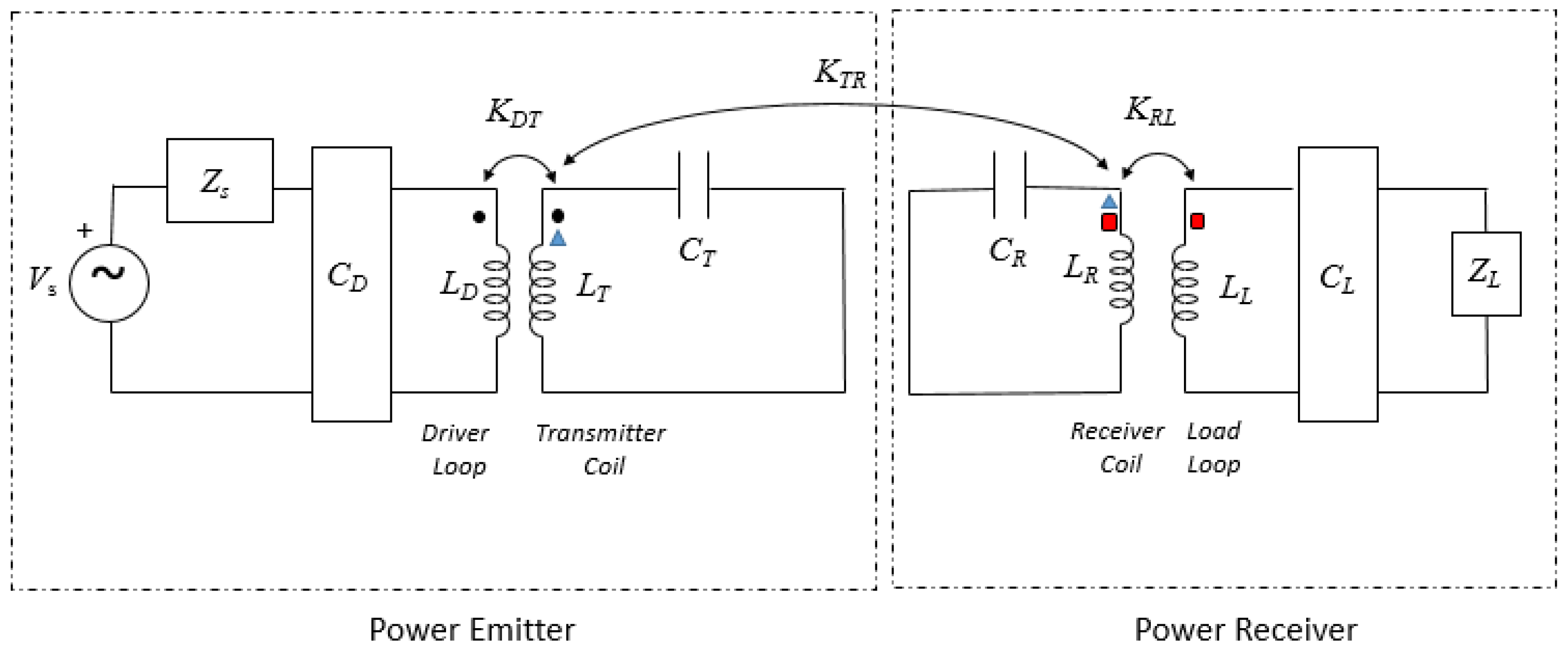
Figure 1 illustrates the four-coil topology and how these coils are usually named: the driver loop, the transmitter coil, the receiver coil and the load loop [
11]. The distance between the receiver coil and the load loop is usually maintained as it is fixed in the construction of the equipment. In some cases, the distance between the driver loop and the transmitter coil can be adjusted by the control system in a way to perform impedance matching. The common use of the SCMR systems in home environments will result in frequent misalignments between the transmitter and the receiver coils, with which the SCMR system must cope.
The meshes and the components related to each coil will be referred with the sub-indexes
D,
T,
R and
L for the driver, the transmitter, the receiver and the load coils respectively. For simplicity purposes, it is assumed that there is only direct relationship between two consecutive coils. Thus, only three coupling coefficients are considered in the electrical analysis (
). In
Figure 1,
models the impedance offered by the load. The load can be a battery or the electric component to be activated to use the home appliance. In addition,
models the internal impedance of the power source.
- (3).
Resonant systems. The system is foreseen to operate under resonant conditions, that means, that the impedance seen by the power source has null reactance. To ensure this condition, all the coils in the system are connected to a capacitor. This capacitor could be a lumped component or a parasitic capacitance resulting from the own coil topology. In the first case, the connection could be in series or in parallel. As in pure-resonant WPT systems, the reactive structures that are added to hold this condition are commonly named as the compensation systems.
- (4).
Two self-resonant coils. The two intermediate coils in the system (the transmitter and the receiver) are designed in such a way that their parasitic capacitance can be employed to resonate. According to the MIT researchers, in this way, the resonance is better. This is the common approach but there are some authors that opt for lumped capacitors in the resonant coils [
12]. It is important to note that the operational frequency of the system may not be always the one imposed by the resonant coils.
- (5).
Operational adjustment. In order to cope with potential misalignments between the transmitter and the receiver coils, it is convenient to tune one of the component of the system. Some control equipment will be required for this adjustment in order to maximize the power transferred to the load or the efficiency. The main adjustments are the frequency tuning and the inclusion of dynamic impedance matching structures.
The combination of these five properties makes the mid-range WPT a reality, even with misalignments. To understand this behavior, the first descriptions of SCMR systems were based on the Coupled Mode Theory. Specifically, a mode represents the electromagnetic energy exchange occurring in a coil between the inductance and the coil’s parasitic capacitor. As the topology of SCMR systems is supported by two self-resonant coils, two modes are employed in the analysis. For a generic coil characterized by its self-inductance
and its parasitic capacitance
, the mode
is defined so that
corresponds to the energy of the reactive components of the coil when the coil is isolated. That means, that for the energy computation, it is assumed that
and
are not coupled with other components in the circuit. Thus:
where
and
are the voltage at the capacitance and the electrical current in the coil respectively. Basing on this new term, the system behavior is defined with two modes.
Alternatively, a mesh-based analysis using Kirchhoff’s Laws is equivalent and it avoids the simplifications associated to the previous theory. Both approaches arise similar results though [
9]. The current trend opts for the study of the SCMR systems basing on Kirchhoff’s Laws [
13], so this is the approach followed in the paper.
According to the conception of SCMR system by MIT researchers, the transmitter and the receiver coils employ their parasitic capacitances to work on resonant conditions (
and
in both sides respectively). In particular, these two coils are equivalently built so their resonant frequency is exactly the same. Specifically, the angular resonant frequency (
is:
The electrical magnitudes at the resonant frequency are marked with the superscript ‘
o’. Because the values of the parasitic capacitances are usually in the range from 1 to 10 pF, the resonant frequency in SCMR systems is commonly in the interval from hundreds of kHz to dozens of MHz [
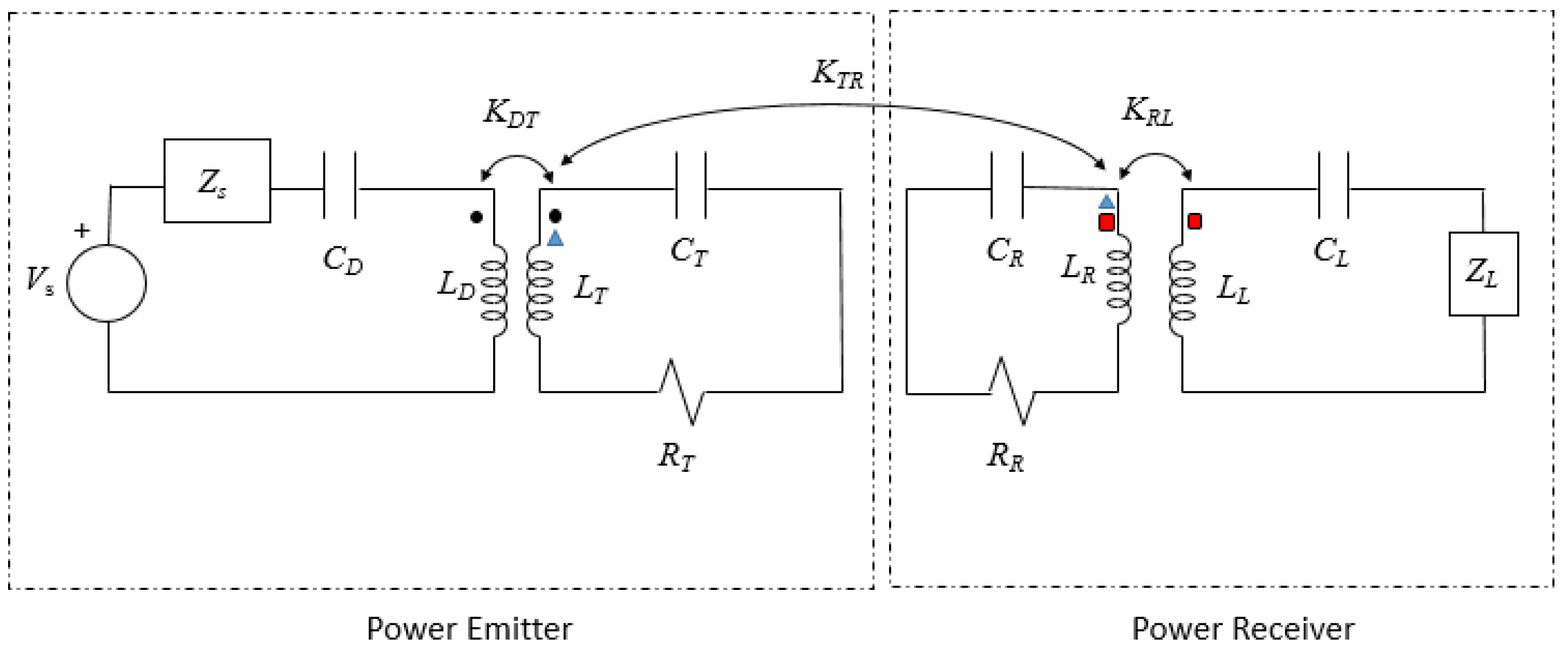
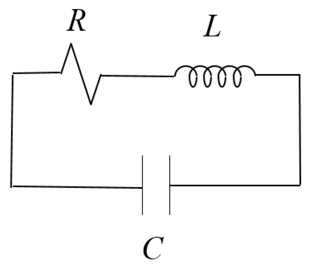
14]. Alternatively, the driver and the load loop are usually connected to a lumped capacitor to ensure the operation under resonant conditions. This reactive element could be connected to the coil in parallel or in series but the most popular connection is in series [
10]. This type of connection will lead to an equivalent circuit as shown in
Figure 2. As can be observed, for a more precise model, the resistances of the coils are included. Considering the typical operational frequency, these resistances are due to two physical effects leading to the ohmic resistance and the radiation resistance [
15]. These two effects are assumed to be independent so the equivalent resistance of the coils is computed as the sum of the ohmic and the radiation resistances. In our model, they will be
and
for the transmitter and the receiver respectively. In contrast, the resistances of the driver and the load coils are not included in the model. This is because they are built with only one loop so that their internal resistance becomes negligible if we compare them to
and
.
The following analysis is based on the concept of the reflected impedance. According to this technique, two meshes with coupled components are simplified as a single one, in which an extra component is included. This additional component will be referred to as
. Thus,
corresponds with the reflected impedance from mesh
to mesh
. In our work, the reflected impedance can be computed with the meshes involved in a SCMR system, that is, the meshes with the driver, the transmitter, the receiver and the load coils. Theses meshes are referenced as
D,
T,
R and
L respectively. Deriving the reflected impedance in the receiver and the transmitter sequentially, we can lead to the input impedance (
). In particular, for the electrical scheme represented in
Figure 2, we have:
At the resonant frequency of the transmitter and the receiver coil, these impedances are:
Thus, with these particular operational conditions, the currents in the four coils are computed as:
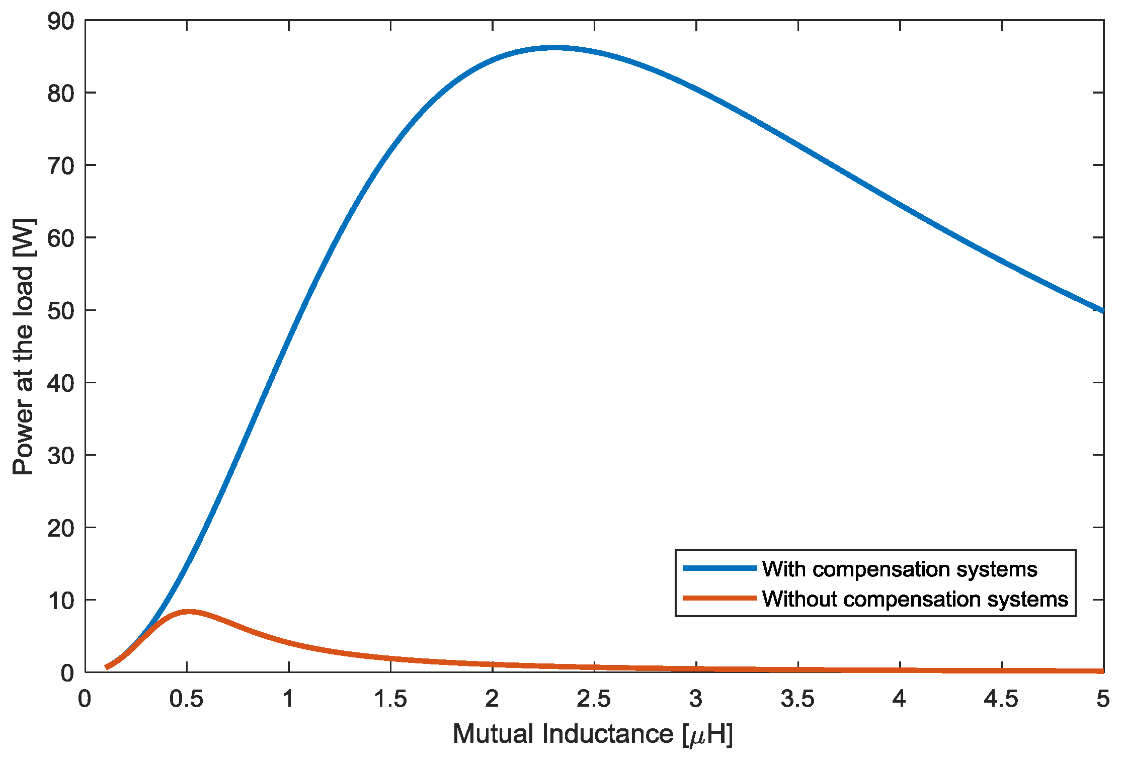
Basing on this analysis, we evaluate the need for the compensation topologies in the driver and in the load. We will demonstrate that for a four-coil topology it is necessary to include them in order to achieve a reasonable operation in terms of power delivered to the load. This is important to remark as the description of some experiments does not explicitly incorporate the compensation systems. The electrical features of the experiment are extracted from [
16] and summarized in
Table 1.
For this SCMR experiment, if we vary the distance between the transmitter and the receiver coil, we are forcing to the variation on the mutual inductance too. For these changes, the power delivered to the load is modified as shown in
Figure 3. It can be clearly observed that the power delivered to the load is reasonable when the compensation systems are included for a wide range of distances separating the transmitter and the receiver coils.
The four-coil topology of SCRM systems could be reduced to a two coupled coil system. For this simplification, the resistances of the four coils are all considered negligible. This model also assumes that the four coils are built to have the same resonant frequency. This means, that the capacitors
and
are set to make the driver and the load loops have the same resonant frequency that the free resonant frequency of the transmitter and the receiver coils. Then:
where the superscript ‘
O’ denotes that the system is working at the resonant frequency and the resistances in the transmitter and receiver coils are considered null.
Basing on the concept of the reflected impedance, we can obtain that:
Operating with this last expression, we obtain that:
This equation reveals that the input impedance perceived by the power source corresponds to the series association of the power internal impedance
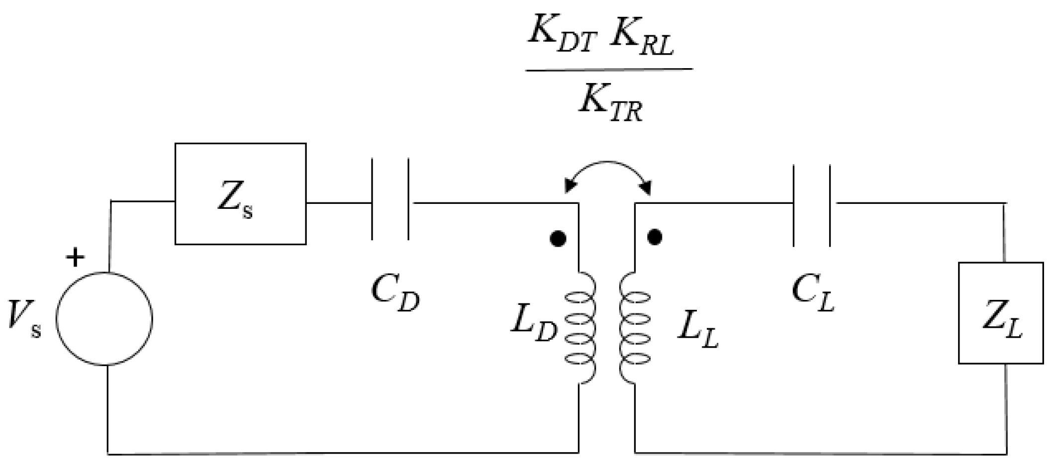
and the reflected impedance from the load to the driver meshes. In particular, the equivalent coupling coefficient (
) for the reflected load is
. As the impedances of the intermediate coils is not affecting the reflected impedance, the four-coil topology can be simplified as a two-coupled coil scheme in which the coupling coefficient equals
. The equivalent two-coil scheme is shown in
Figure 4.
Due to the previous simplifications, the model based on two-coupled coils is only exact when the system operates at resonance and the losses in the resonant coils are not relevant. However, this model is practical in order to derive important conclusions about the performance of SCMR systems.
With this equivalent circuit we can explain why the indirect-link presents a better power transfer than two simple coupled coils. This is due to the coupling coefficient of the equivalent circuit of the SCMR system. The coupling coefficient of two coupled coils indicates how much of the magnetic flux generated by the primary coil (the driver in the simplified circuit of
Figure 4) is used to induce a voltage in the secondary coil (the load). With two coupled coils, it is desirable that the coupling coefficient approximates to 1. However, in conventional resonant WPT systems, this condition cannot be satisfied as it will force the two coils to be too close. This is in fact the reason why some wireless chargers for home appliances (e.g., electrical toothbrushes and mobile phones) only operate when the device is in contact with the charger. This requirement, which imposes a clear restriction, is avoided in SCMR systems. Basing on the equivalent circuit of a four-coil topology, the requirement is expressed as:
Then, when the individual coupling coefficients (mainly due to ) are not equal to one, could be the unity as expressed in Equation (17). This condition explains why SCMR systems can get more efficiency that pure resonant systems because when the transmitter and the receiver are largely separated (their coupling coefficient is close to 0), the efficiency is not greatly affected if the other coupling coefficients ( and ) are designed according to Equation (17). In contrast with a simple two coupled coils, this may be greater than 1, resulting in an increased efficiency. So, selecting the proper values of and , the distance between the transmitter and the receiver in SCMR systems can be enlarged for an efficient wireless power transfer. However, other performance metrics such as the power delivered to the load may be affected as we will discuss next.
In order to illustrate the benefit of using four coils for the WPT system, we compare the efficiency of a 4-coil topology with the one achieved by a traditional 2-coil topology. For the SCMR system, the electrical features summarized in
Table 1 are set. In contrast with the development of the equivalent circuit of
Figure 4, the internal resistances of the resonant coils have been considered so we will observe that the previous conclusions are still valid. The 2-coil topology used for this comparison consists of the voltage source connected to the transmitter coil and the receiver coil connected to the load. The resistances and the capacitances of these two coils are included. The driver and the load loops are suppressed in the 2-coil system.
Table 2 summarizes the performance metrics obtained for a constant distance between the transmitter and the receiver coil. Specifically, the mutual inductance for these two coils is 0.86 µH. In the four-coil system, the distance between the driver and the transmitter coils is modified in the same way than the separation between the receiver and the load coils. Thus,
. We have studied the system for three different
in terms of efficiency, power delivered to the load and induced voltage in the load coil. The efficiency is defined as the ratio between the power delivered to the load to the power generated by the source.
We can observe that including the driver and the load coils have increased the efficiency for the three cases considered in this analysis. When , this increment is achieved without practically altering the power delivered to the load or the induced voltage. Nevertheless, these two metrics are clearly decremented when the is increased although the efficiency is also improved. In the design process it should be decided which performance metrics prevails in order to decide about the coupling coefficients of interest.
For the three previous coupling coefficients
, we will further analyze how the system works for a wide range of distances between the intermediate coils. This analysis is reflected in
Figure 5. In the
x-axis, the mutual inductance reflects the mutual inductance between the transmitter and the receiver coils for both the 4-coil and the 2-coil topologies. This parameter can be considered as the opposite to the distance separating both coils.
Figure 5 shows how the three topologies of the SCMR system are able to operate with lower mutual inductances
, that is, for bigger distances between them. However, SCMR systems present two main disadvantages in comparison with pure-resonant systems. Firstly, they are more expensive and complex in their design as they require four coils. Secondly, the system becomes less compact. This last disadvantage is solved with the conformal configuration, commonly employed in biomedical applications where it is a strong requirement to operate with compact systems inserted in the patients. In a conformal configuration, the transmitter coil and the receiver coil are both built and placed in the same plane than the driver and the load loop respectively.
Another conclusion that this figure arises is that SCMR systems are very sensible to distance between the transmitter and the receiver coils as the efficiency varies with this parameter. Control systems should be included to support misalignments, then.
3. Frequency Splitting Phenomenon
In the design of SCMR systems, the proper values of the electrical components are determined according to realistic and potential modes to build them. Several options are possible for the components. For instance, the topology of the coil (structure and number of turns) could be diverse. In order to decide which option is the most convenient for a particular application, other considerations about the main properties of SCMR systems need to be taken into account in the design process too. In particular, it is of importance to consider how some variations on the system parameters could alter the system stability. While SCMR circuits are operating, two main modifications could take place: changes on operational frequency due to the system control and variations of the coupling coefficients due to the different distances between the coils. These changes could lead to two effects that could impact on the system performance and even on its reliability. These effects, which are related, are the frequency bifurcation and the frequency splitting.
Frequency bifurcation occurs when the input impedance has a null reactance at least at three different frequencies [
16,
17]. The consequence is that the main electrical magnitudes at the output holds a particular relationship with the variation of frequency. Specifically, there are peak values at those frequencies with null reactance that are not the resonant one. An equipment where frequency bifurcation may occur should be designed to support the peak values (current and voltages in some electrical components) related to the frequency bifurcation if the operational frequency may be adjusted. As an alternative, the system could be designed to prevent this kind of performance. Towards this goal, a pure-resonant system with just two coupled coils establishes a mathematical condition based on the quality factors of the coils that must be satisfied to prevent the frequency bifurcation [
17]. These equations, which depend on the compensation systems, are not applicable for SCMR circuits as they base on a four-coil topology. Moreover, SCMR systems can be designed to work at those frequencies where the peak occurs, as we will study next.
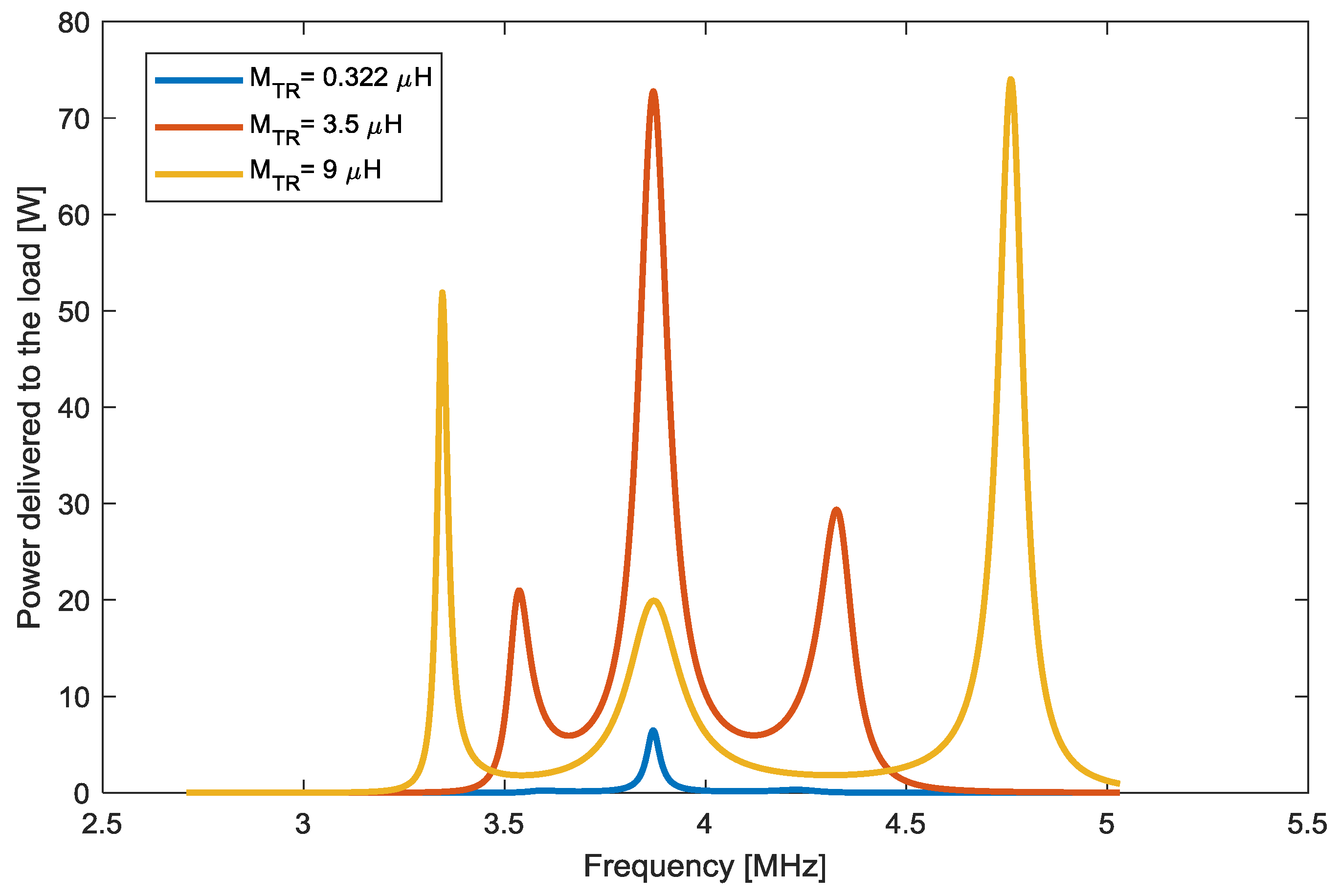
In order to have a safe operation of the SCMR system, it is necessary to determine when the frequency bifurcation occurs in order to avoid the potential damages of the peak values. For a particular SCMR system, the frequency bifurcation appears or not depending on the separation between the transmitter and the receiver coils. Thus, if the coupling between the transmitter and the receiver coils exceeds the splitting coupling, bifurcation takes place and consequently some electrical magnitudes in the circuit (e.g., power delivered to the load, current in the coils or efficiency) exhibit some peak values in a range of frequencies. Otherwise, if there is no frequency splitting, the maximum of the electrical magnitudes is only at the resonant frequency. This behavior is illustrated in the next figure.
Following with the SCMR system characterized by the features in
Table 1, we have modified the distance between the transmitter and the receiver coils leaving the rest of the parameters constant. The results are presented in
Figure 6. When the mutual inductance
is 0.32 µH, the power delivered to the load is maximum at the resonant frequency, that is, at 3.87 MHz. However, if this distance is reduced, there are also some maximum values at other frequencies. In particular, for
, the power delivered to the load at 3.4 MHz is even greater than the one obtained at 3.87 MHz. The position of these maximum depends on the distance between the resonant coils as it is illustrated by yellow and red lines in
Figure 4. For some metrics, such as the efficiency, the maximum value with frequency bifurcation may not occur at the free resonant frequency
.
In [
18], the frequency splitting is reflected as the addition of two peaks leading to a total of four power peaks. Thus, when there is no frequency splitting, there are two peaks but then, the system counts on four peaks. The authors demonstrate that the coil topologies clearly affect in the type of behavior the system presents. Thus, for the same distance between the resonant coils, the system could have a frequency splitting with four-peaks, two peaks or even it could have no frequency splitting.
The work in [
19] defines the critical coupling for a four-coil topology system and it relates this parameter to coil quality factors. For a topology with the same structure for the resonant coils (with quality factor
and internal resistance
) and equivalent loops (with quality factor
and internal resistance
) the critical coupling (
) is demonstrated to be:
The quality factors
and
are computed as:
For the quality factor
, the angular frequency is the free resonant frequency of the intermediate coils, that is,
as expressed in Equation (2). For the quality factor
, the parasitic capacitances of the loop (
) should be estimated as:
Considering the frequency splitting phenomenon, the modes of operation of a SCMR are two:
- -
The overcoupled region, when . It occurs when the transmitter and the receiver coils are close. The performance metrics present some peak values at frequencies different from the free resonant one.
- -
The undercoupled region, , when the distance between the two resonant coils is considerable and the bifurcation does not take place.
The frequency splitting phenomenon has been observed in more complex structures too. In [
20], a SCMR scheme with multiple transmitters is analyzed. The system is configured to work at one of the power peaks in the overcoupled region.
4. Control in SCMR Applications
SCMR systems are equipped with control applications that aim to improve the performance in order to support the freedom to place and freedom to move requirements. We have observed that the SCMR systems allows for the wireless power transmission between two objects that are separated in a distance greater than the one of the resonant systems. For a set of conditions (distance between the transmitter and the receiver and load resistance), there is an optimal frequency and/or an optimal impedance in which the system works according to the predefined design goal. When working with SCMR systems, there are two main goals that can be set in the design process:
- -
Operate at maximum efficiency.
- -
Operate to transfer the maximum power to the load.
SCMR circuits are expected to be used in home environments, their power requirements are limited. Thus, they are usually designed so that the source transfers the maximum power to the load (the device to power or charge). In this design process, losses occurring in other resistances are not considered relevant. In this approach, the design of strongly-coupled magnetic resonant circuits usually focuses on transferring the maximum power to the load independently of the efficiency of the system.
Small deviations from the set of conditions assumed in the design process (mainly coil misalignments) would lead to the decrement of the efficiency or powered transferred to the load. Although complex structures of the coil may alleviate this effect, the system converts into a bulky structure which is not always feasible to implement. This is the case of the advanced geometries for the transmitter and the receiver coils proposed in [
21], where two orthogonal coils try to capture the magnetic field in two different spatial axis in order to increase the efficiency.
In order to support this misalignment, two main schemes are proposed for the control technique. These schemes are the adjustment on the operational frequency and the modification of the impedance matching structures. Both control strategies can be employed for the two aforementioned goals: maximize the efficiency and/or maximize the power delivered to the load.
Although the control of the operational frequency seems to be more common in pure-resonant systems, SCMR circuits usually operate under rigid requirements about the ISM band [
22]. Thus, it is not always possible to opt for this scheme. In contrast, the dynamic configuration of the impedance matching may be more practical. The main shortcoming is that it is not always easy to count on impedance matching structures with a wide range of potential impedance values. These strategies are reviewed next.
4.1. Frequency Tuning
In order to make the SCMR able to power a device with changes in the position where it is placed, the frequency tuning bases on the frequency splitting phenomenon. According to this strategy, the system is configured to operate in the overcoupled region. Alternatively, if the system is going to work with predefined and set spatial conditions, the undercoupled region is the best option as it avoids the control equipment.
Thus, the frequency tuning control adjusts the frequency of operation so that it is one of the peaks that reveal themselves when there are frequency splitting. In particular, for the efficiency, the frequency splitting in SCMR system described with
Table 1 leads to a maximum that is not placed in the free resonant frequency
.
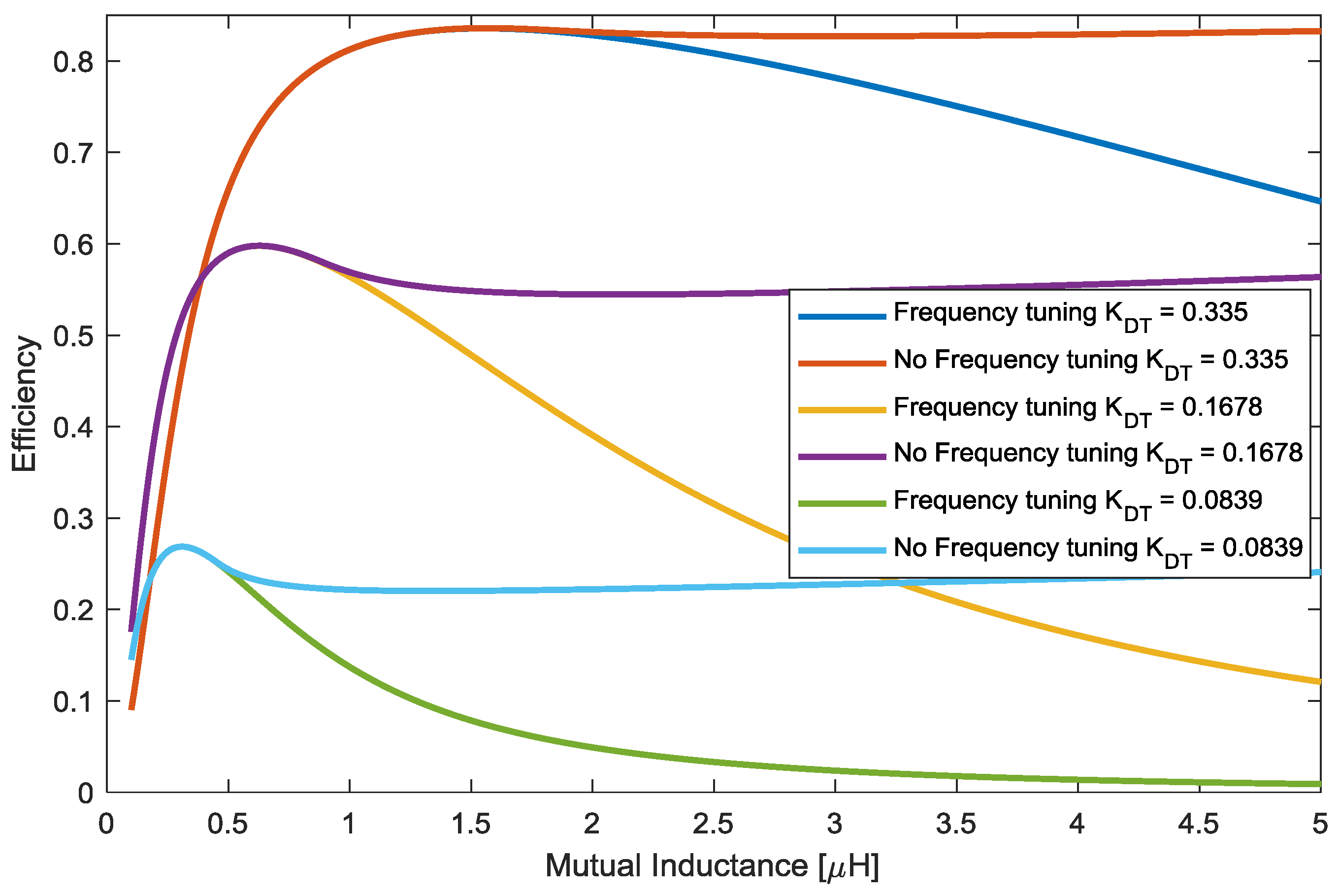
Figure 7 shows how the efficiency is greatly improved when the frequency tuning is executed for this SCMR system with three different
.
Figure 7 shows the capability of the frequency adjustment to achieve a nearly constant efficiency in SCMR circuits. For the SCMR system described in
Table 1, we have varied the distance between the transmitter and the receiver coils, that is, their mutual inductance. For each particular distance, we have computed the efficiency of the system for a range of potential operational frequencies in which the SMCR system may operate if properly adjusted. The most convenient frequency, referred to as the optimal frequency, is identified as the one in which the efficiency of the system is the greatest one. With the metrics associated to this optimal frequency, we have derived the performance of the SCMR system referred to as ‘frequency adjustment’.
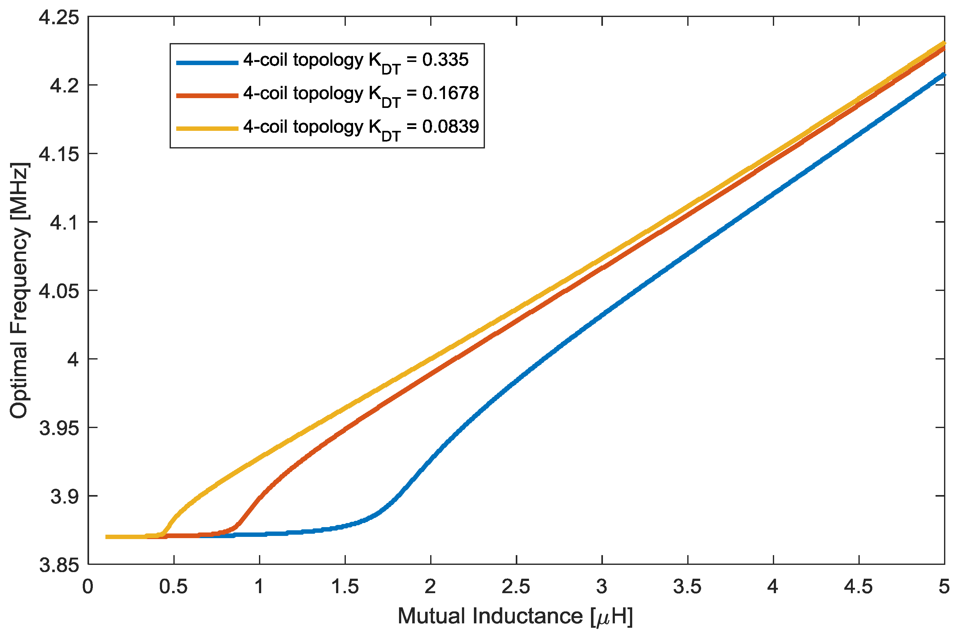
Figure 8 reflects how the optimal frequency is constant for low mutual inductances, but it needs to be adjusted when the distance between the resonant coils decreases if we want to achieve a high efficiency. This behavior is observed for the three different 4-coil topologies tested in this paper. The frequency from which the optimal frequency is not constant is related to the
. It can be observed that the
depends on the coupling coefficient
. The optimal frequency could be computed to maximize other performance metrics such as the power transferred to the load. For this metric, the behavior will be similar as the need for adjustment is related to the occurrence of the frequency bifurcation. The frequency bifurcation leads to peak values in other frequencies different from the resonant one.
Figure 8 shows that the variations on the frequency required by the control adjustment are not considerable so this control system can be implemented with conventional power converters. The work in [
19] proposes the first relevant control for SCMR systems based on frequency tuning. For the implementation, they incorporate a directional coupler in the driver loop. With this component, they measure the incident and reflected power. Consequently, the frequency is adjusted according to these measurements.
4.2. Impedance Matching
As we have demonstrated previously, compensation systems are necessary to transfer a convenient power to the load. Pure-resonant systems usually aim at being efficient as they manage a kW-power transfer. However, impedance matching structures in SCMR systems can be used to maximize the efficiency or the power delivered to the load.
The works in [
13,
23] presents a comprehensive analysis about the value that the load should take to achieve maximum efficiency or maximum power in the load. The electrical features of the load cannot be always adjusted so that additional components should be inserted in the source to achieve any of these two goals. The impedance matching network consists of the connection of capacitors, inductances and resistances so that the global impedance corresponds with the one demanded.
Basing on the maximum power transfer theorem, the source impedance (
) should be the complex conjugate of the impedance of the rest of the system if the power delivered to the load is expected to be maximized. As we are working with coupled coils, we can use the reflected impedance concept in the equivalent circuit of a SCMR presented in
Figure 2.
Under resonant conditions, the impedance reflected from the load to the primary (
) is:
According to the maximum power transfer theorem,
. So:
The system needs to incorporate impedance matching structures so that these two conditions are verified. The most popular scheme for SCMR system is the Series connection in the driver of the matching network. As can be observed, the optimum values for
and
depend on the coupling coefficients. So, if dynamic conditions occur while the system is working, these coefficients are expected to vary and, in turn, the optimal matching structures need to be adjusted to obtain an optimal performance. The work in [
24] evaluates the use of adaptable matching structures. Although it demonstrates the utility of this type of blocks, the practical implementation requires complex measurements. Reference [
22] includes a set of capacitors and resistances in the transmitter and the receiver coils. One of the capacitor and a resistance is elected to work close to the optimal operating point established by the maximum power transfer theorem. Reference [
25] includes a tunable matching structure in the driver and the load loops. The most relevant feature is that there are a set of driver and the load loops so that one of them is switched on according to the instantaneous conditions of the system.
An alternative is proposed in [
26]. Based on Equations (23) and (24), the maximum power transfer can also be achieved by altering the coupling coefficients (
and/or
) when the distance between the resonant coils is modified. This is referred to as the coupling matching. Particularly, in [
26] the distance between the driver and the transmitter coil is mechanically varied to approximate to the optimal condition set by the maximum power transfer theorem. In this way, the receiver, which may have more restrictions for the adjustment, do not require any control system. This restriction is also considered in [
27], where
is varied to adapt to the changes on the position between the transmitter and the receiver. Specifically, the driver loop is selected among a set of two coils and connected to the circuit accordingly. In this experiment, the receiver follows a conformal implementation. As shown in
Figure 8, the variation of the
may impact on the critical coupling coefficient so the frequency splitting phenomenon should be considered in the design of the systems that implement this control method.
5. Coil Design in SCMR Systems
They key component of a SCMR system is the coil, as their self-inductance and quality factor determines if it is feasible to work in the overcoupled region. Their topology and features also impact on the capability of the system to work under misalignments. Moreover, the type of coil defines the parasitic capacitance and, in turn, the resonant frequency.
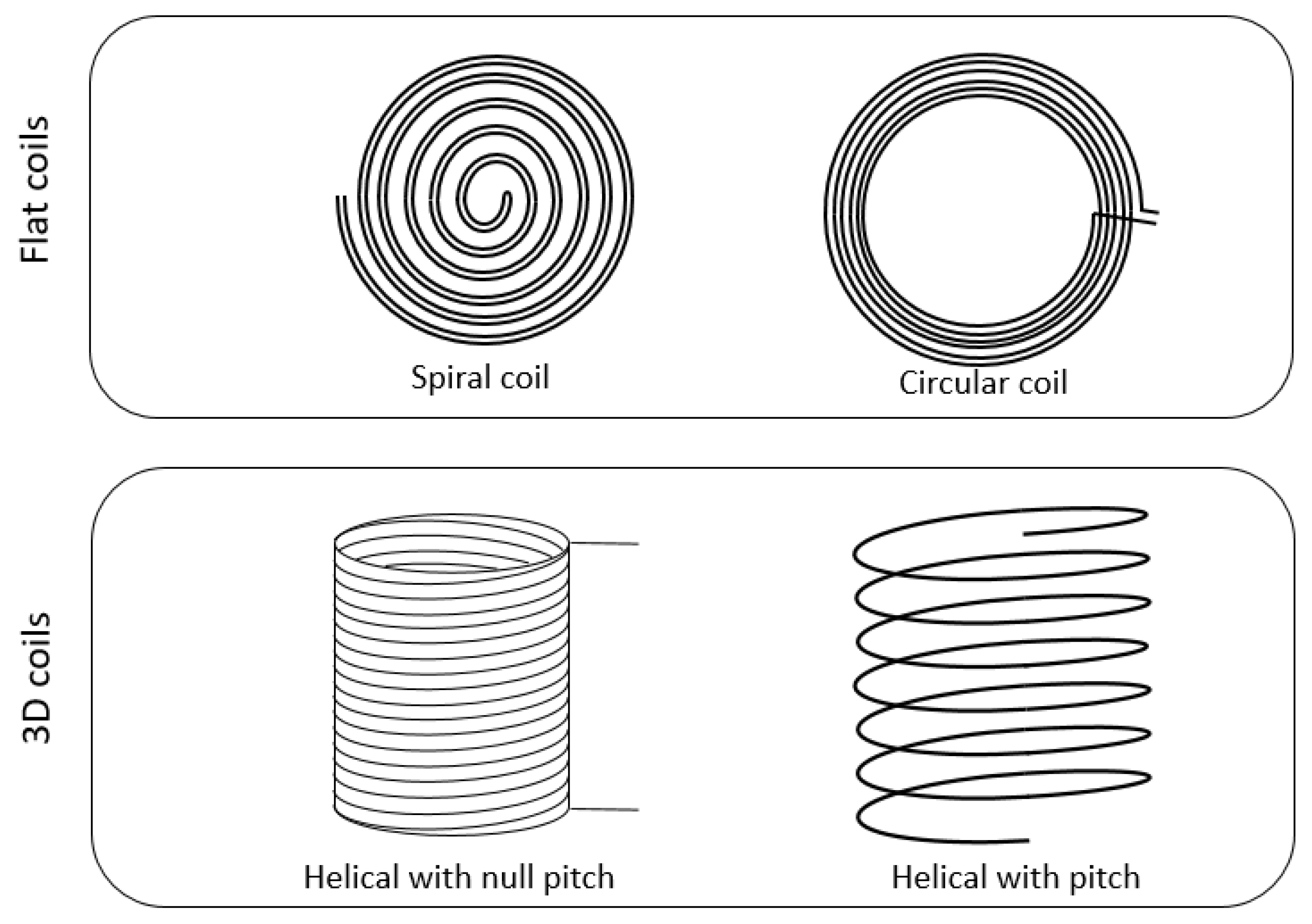
In SCMR circuits, the coils are air-core. They can be classified into two main groups according to their topology: flat and 3-D. The flat coils can further be spiral or circular. Alternatively, the 3-D coils can be helical with or without distance between two consecutive turns. This distance is referred to as the pitch. An illustration of this kind of coil topology is presented in
Figure 9.
Conformal solutions constitute a particular case of circular coils in which the transmitter coil is in the same plane than the driver loop so that the dimensions of the transmitter equipment is reduced [
27,
28]. A more popular approach for conformal implementations searches the compact structure in the receiver, which may have more restrictions about the place to occupy. This is typical in biomedical applications.
For the design of SCMR systems, it is important to count with the electrical characterization of the coil. Although a numerical-based analysis is possible to derive the equivalent electric circuit of a coil, the use of a model requires less computational resources. Thus, models can be incorporated in the design process based on the selection of a configuration among a space of potential solutions as the space of solutions can be computed in a reasonable time. The most popular model for coil includes a self-inductance (
), a resistance (
) and a capacitance (
) as shown in
Figure 10.
The values of these elements depend on the coil topology and on the material it is composed of. Moreover, the resistance is also affected by the operational frequency whereas the inductance and the capacitance are assumed to be constant in a wide range of frequencies. Specifically, the self-inductance of a coil may be approximated by Wheeler’s model or Waters’ model [
29].
As exposed in [
30], the stray capacitance (
) of an air-core coil is the result of two effects. The first one is related to the capacitance between adjacent turns whereas the second one is due to the capacitive effect between the turns and the shield. In SCMR applications, the used conductors are typically without shield so this contribution is neglected. The general approach to model this parameter initiates by estimating the capacitance between two adjacent turns, the referred to as the capacitance turn-to-turn (
). Then, for a coil of
turns, the capacitance (
) is computed as the series association of the
between the (
turns. A more accurate but more complex model is presented in [
31]. The work in [
32] proposes a model for spiral coils to estimate the self-inductance and the capacitance. The model, which is based on transmission line theory, is complex to apply. An alternative procedure to determine the self-capacitance consists of computing the self-resonant frequency of the coil. The work in [
33] presents a method to estimate the self-resonant frequency of spiral coils. As described, this parameter depends on the pitch, the cable width, the radius and the number of turns of the coil. The relationship between the self-resonant frequency and the coil structural parameters is determined basing on a particle-swarm optimization problem.
Finally, the resistance is due to the power losses that all practical inductances exhibit. This resistance increases with the indictor operating frequency, mainly because of the skin and proximity effects. The total resistance is then computed as the sum of the ohmic resistance (related to the skin effect) and the radiation resistance (due to the proximity effects). As previously commented, this two types of resistances depend on the frequency. High-power applications, such as the ones for EV wireless chargers, opt for coils based on Litz wire [
34] as they operate in the interval of tens of kHz. However, this work demonstrates that for the typical operational frequency of SCMR systems (some MHz), the resistance associated to the copper coils is lower than the ones basing on Litz wire. On the other hand, the component due to proximity losses reflects how some current densities are induced in the winding because of the magnetic fields involved in the system. This implies that variations on the magnetic field will alter this term. The work in [
35] demonstrates how the mutual coupling impact on the resistance of the coils.
Concerning the material of the coils, they are usually built with copper. However, recent works show how coils built with superconductor present a reduced internal resistance and a high quality factor [
36]. The cost of a coil made of a superconductor is higher, though.
As previously said, the use of a model to characterize the coil is especially convenient for the design phase. In order to decide the exact parameters of the coil (topology, number of turns and pitch), it is necessary to take into account the application requirements, that is, the power that needs to be transferred, the common distance between the transmitter and the receiver, the size that the transmitter and the receiver equipment could acquire and the range of frequencies in which it could operate. An iterative algorithm should then be applied in order to know which combinations of electrical features satisfies all the requirements. Among them, the costs or the size diminution could be the criterion to select the final coil structure to be built.


