Abstract
Frost layer on the outdoor air heat exchanger surface in an air-source heat pump (ASHP) can decrease the system coefficient of performance (COP). Although the common defrosting and anti-frosting methods can improve the COP, the periodic defrosting not only reduces the system energy efficiency but also deteriorates the indoor environment. To solve these problems, it is necessary to clearly understand the frosting phenomenon and to achieve the system frost-free operation. This paper focused firstly on the analyses of frosting pathways and frosting maps. Followed by summarizing the characteristics of frost-free technologies. And then the performances of two types of frost-free ASHP (FFASHP) systems were reviewed, and the exergy and economic analysis of a FFASHP heating system were carried out. Finally, the existing problems related to the FFASHP technologies were proposed. Results show that the existing frosting maps need to be further improved. The FFASHP systems can not only achieve continuous frost-free operation but reduce operating cost. And the total COP of the FFASHP heating system is approximately 30–64% higher than that of the conventional ASHP system under the same frosting conditions. However, the investment cost of the FFASHP system increases, and its reliability also needs further field test in a wider frosting environment. In the future, combined with a new frosting map, the control strategy for the FFASHP system should be optimized.
1. Introduction
With increasing promotion of energy-saving and emission-reduction policies in China, space heating and hot water supply modes are gradually being transformed from the ways for traditional small coal-fired boiler and scattered coal burning to a clean heat supply system, and that is so-called Coal to Clean Energy or Coal to Electricity. The clean heat supply is defined as using one or more clean or renewable energy, such as electricity (including heat pump system [1,2] and electric boiler), natural gas, biomass and solar energy, to achieve low emission and low energy consumption for heat supply process through a system of high efficient transmission and distribution network and buildings of energy-saving. In all the above mentioned clean and renewable energy resources, an air-source heat pump (ASHP) system is a kind of renewable energy device transferring heat energy from a low-temperature heat source to a high-temperature heat source called a heat sink, using a small amount of electricity [2,3]. As shown in Table 1 (the calculation parameters see the literature [4]), compared with the traditional heating way, the ASHP system not only can decrease the amount of primary energy consumption and pollutant emission but can reduce operation cost [4,5]. Therefore, the popularization of the ASHP system will contribute to the development of the clean heating industry in China. According to the development reports of ASHP market in China in the first half of 2017 and 2018, the number of new installations for the ASHP is increasing year by year, especially in the first half of 2017, its rate of increase is about 50%. In the first half of 2018, the share of ASHP systems in space heating can up to 30%. And the commercial space heating accounts for 12.5% of the heating market.

Table 1.
Comparisons of primary energy consumptions, carbon dioxide emissions and heating running costs of different heating modes [4].
Frost formation will occur inevitably on the surface of the outdoor air heat exchanger for the ASHP system operating in a cold and humid environment, when the surface temperature is below both the dew point and the freezing point [6,7,8]. During the early initial period of frost formation, the frost crystals depositing on the heat transfer surfaces play the roles of increasing surface area and surface roughness [9,10]. This may enhance the heat transfer between the surface and the outdoor air [11,12]. However, with the growth of frost layer, the frost accumulation may cause two problems as follows: (1) an increase in heat transfer resistance between the air and the cold surface and a decrease in heat transfer efficiency [8]; (2) an increase in the resistance of air flowing through the heat exchanger, a reduction of air mass flow rate and an increase of pressure drop in the air-side and power consumption [13,14]. As a result, the COP of the ASHP system is significantly degraded [15]. These have been extensively confirmed by scholars in the world. For example, Emery and Siegel [16] previously reported that the heat transfer rate decreased by about 50–75% and the pressure drop increased dramatically because of the frost formation and accumulation on compact heat exchanger. And the recent results provided by Timmermann et al. [17] also showed a similar trend. Moreover, Sanders [18] indicated that the heat transfer capacity of the ASHP system could be reduced by more than 35% under frosting conditions. Kwak and Bai [19] showed that under frosting conditions, the COP of the conventional ASHP unit was decreased by about 53% as operation time increased from 25 min to 100 min. In summary, the application of the ASHP system are limited in the cold and humid area.
To promote the rapid development of ASHP technology and the successful implementation of Coal to Electricity policy in China, the anti-frosting and defrosting technologies are focused by researchers worldwide in recent years [14]. According to the references, the anti-frosting technologies include changing the characteristics (temperature, velocity [20], humidity [21], pressure [22] and purified air [23]) of inlet ambient air, changing the cold surface temperature [24], surface treatment [25], changing the structure of air heat exchanger (fin-tube geometry [26,27,28], fin spacing [29,30], fin type [31,32]), changing the interaction between air or frost layer and cold surface (electric field [33], ultrasonic wave [34], magnetic field [35] and low frequency mechanical oscillation [36]). And the defrosting technologies mainly have reverse cycle [37], hot gas bypass [38], electrical heating [19,39,40], warm-air defrosting [41], compressor shutdown [42], hot water spray [43], phase change heat storage, electric field [44], ultrasonic wave [45], magnetic field [46], air-particle jet [47], control strategy [48] and waste heat recovery [49,50]. In the above various technologies, the conventional reverse cycle (in various units) and the hot gas bypass (in industry units) defrosting technologies are the most widely used. The surface treatment, the control strategy, the waste heat recovery, the phase change heat storage and the changing the structure of air heat exchanger technologies will have important development prospects in the future. Other technologies (e.g., magnetic field, air-particle jet, electric field and low frequency mechanical oscillation) are only in the research stage and are not applied in actual industrial production. In addition, the compressor shutdown, electrical heating and the hot water spray technologies will tend to be abandoned to promote and apply.
Although the performance of the ASHP system can be obviously improved using the defrosting and anti-frosting technologies mentioned above, no one can achieve frost-free operation of the system under frosting conditions while both the system performance and the indoor environment are not deteriorated. This means that the defrosting mode needs to be turned on periodically in winter. To solve the problem fundamentally, some scholars focus on investigating frost-free technology for the ASHP system operating in frosting region in recent years. And some frost-free air-source heat pump (FFASHP) systems have been developed in published research. These systems can realize frost-free operation under frosting conditions, while taking heat energy from the moist air and releasing the heat to refrigerant [51,52,53]. Through extensive consulting literature materials, it can be found that the articles related to the frost-free technology focus mainly on studies published from 2010–2018. To provide an effective tool for scholars and equipment manufacturers to promote the implementation of Coal to Electricity policy in China, this paper will review the existing frost-free technologies in the published literature, based on the analysis of frosting phenomenon.
The roadmap of this paper is shown in Figure 1. The frost formation phenomenon on the surface of outdoor air heat exchanger for the ASHP system will be firstly analyzed and summarized from frosting pathway and frosting map, respectively. Secondly, the characteristics of the frost-free technology will be summarized and presented. And then the performances of the FFASHP heating and the FFASHP water heater system proposed in recent years will be reviewed and compared with that of conventional ASHP system. At the same time, the exergy analysis of a FFASHP system will be carried out, and its extra investment cost and payback period will be also estimated. Finally, combined with the frosting phenomenon, the future researches to develop the frost-free technology for the ASHP system will be given from four aspects: optimization of system performance, new material (liquid/solid desiccant), new method, optimization of the control strategy.
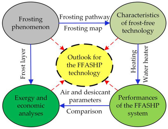
Figure 1.
Roadmap of the present paper.
2. Analysis of Frosting Phenomenon for an ASHP System
2.1. Frosting Pathway
Figure 2 is phase diagram of water. As we can see, the phase diagram of water was divided into three single-phase zones (ice, water, vapor), three two-phase coexistence zones (ice-water, water-vapor, ice-vapor) and one three-phase coexistence point (ice-water-vapor) in according with the aggregation state of water [54]. Figure 2 also shows that the vaporization curve, the melting curve and the sublimation curve were the boundaries of three single-phase zones, whose intersection point was defined as three-phase coexistence point or triple point. For pure water, the temperature Ttp of the triple point is equal to 0.01 °C, and the pressure Ptp equals 612 Pa.
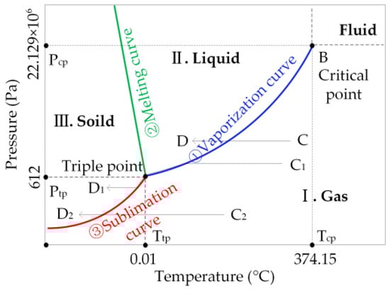
Figure 2.
Phase diagram of water [54].
In addition, as shown in Figure 2, the only condensation phenomenon (C→D) occurred on the cold surface under ideal condition, when the partial pressure Pv of water vapor is greater than the triple point pressure Ptp (Pv > Ptp) and the cold surface temperature Tcs was higher than the triple point temperature Ttp but lower than the wet air dew point Tdp (Ttp < Tcs < Tdp) [55]. Meanwhile, we can also see from Figure 2 that there are three kinds of different pathways to form frost layer, and that is gas-liquid-solid process (C1→D1), gas-solid process (C2→D2) and occurring simultaneously (C1→D1 and C2→D2) [22,55]. The results provided by Xu [56] also confirmed it. The process C1→D1 revealed that when Pv > Ptp, Tdp > Tcs and Tcs < Ttp, the condensation water firstly appeared on the cold surface, followed by being frozen and finally the frost formation occurred with decreasing Pv on the surface of the frozen water droplets. This is a common frost formation process. For the process C2→D2, when Pv < Ptp and Tcs < Tdp, the vapor in moist air may directly change to frost or frost crystal [57] through desublimation, theoretically. In addition, sometimes the process C1→D1 and C2→D2 may coexist at different sites of the cold surface due to the difference of the Tcs and the Pv. Furthermore, it should be noted that the transition time of the phase change process C1→D1 was random in the same conditions. And a probability model (Pro.) related to time was proposed, as expressed in Equation (1) [55].
where, a is the delay time of occurring transformation, s; and b is the speed of phase change, m/s. They were affected by degree of subcooling, water vapor pressure and surface temperature. If the t ≤ a, the subcooled water droplets on the surface were not frozen. The freezing must take place if the cold surface temperature was below 0 °C and t→∞ [55].
At the same time, some previous studies [58,59] pointed out that the condensed water droplets existed a certain degree of supercooling under actual situation. The result provided by Kim et al. [60] also revealed the above conclusion. They measured the change of sessile droplet temperature with time on a cold surface (its static contact angle was 75 ± 1°), when the cold surface temperature, the outdoor air temperature (Ta) and relative humidity (RH) were held constant at–10 ± 0.2 °C, 25 ± 1 °C and 30 ± 3%, respectively, without forced air flow around the cold surface [60]. The results are showed in Figure 3. As shown in Figure 3, during the supercooling, the temperature of the water droplet on the surface was cooled below 0 °C and then stabilized at −8.19 °C for 127 s, but was not frozen. Hence, to achieve no-frost on the air heat exchanger surface under frosting condition, the ambient air and water droplets on the cold surface of constant temperature during the whole heat transfer process should be respectively maintained the cooling state and supercooling state [55].
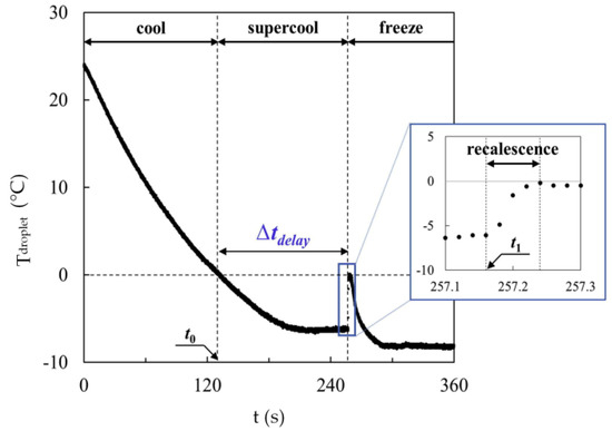
Figure 3.
The change of a condensed water droplet temperature on a cold surface [60].
In addition, from the viewpoint of phase change kinetics, the phase change driving force leads to the freezing of the water droplets [61]. Chen et al. [22] showed that a smaller phase change driving force will be obtained if the partial pressure of water vapor or atmospheric pressure decreases under keeping other conditions constant. This will contribute to keeping the cooling state of ambient air and the supercooling state of the water droplets without being frozen. Therefore, to realize the frost-free operation of the ASHP system, the essential conditions for various frosting pathways should be changed in time.
2.2. Frosting Map for an ASHP System
2.2.1. Parameters Describing Frosting Map
It is well known that frosting is a transient phenomenon along with heat and mass transfer process. This phenomenon is mainly influenced by the parameters as follows: temperature and wettability on the surface of an air heat exchanger, velocity of the inlet air, relative humidity of the inlet air (RH), inlet air cleanliness and temperature (Ta) [62,63]. To obtain accurately and comprehensively the conditions of various frosting pathways, developing a frosting map for the ASHP system is recommended by some scholars. According to the study of Zhu et al. [63], when developing the frosting map, it was necessary to do some reasonable assumptions. For example, (1) air cleanliness and the wettability of the surface of air heat exchanger were not included because these parameters were not easily quantified; (2) a constant air flow velocity ranging from 1.5 to 3.5 m/s was set at the inlet of air heat exchanger; (3) the refrigerant mass flow rate was evenly distributed to each circuit; (4) the speed of the compressor was a constant value [63].
However, the effects of ambient air temperature and RH on frosting phenomenon cannot be ignored. As shown in Figure 4, frost formation would become more difficult to occur with decreasing air humidity and increasing air temperature. In contrast, frosting would become easier with increasing the humidity and with decreasing the temperature [64]. And many studies have shown that both reducing inlet air humidity and preheating inlet air could be beneficial for frost retarding [26,65,66] and even avoid frosting phenomenon [67]. For example, Wang and Liu [67] pointed out that frost formation could be entirely avoided on the air heat exchanger surface for the ASHP system with integrated a solid desiccant-coated heat exchanger placed before the evaporator. Kwak and Bai [19] found that the heating capacity and COP of the system increased significantly by 38.0% and 57.0%, respectively, when an electric heater fixed at upstream of air heat exchanger in the ASHP unit was used for heating the inlet air when the outdoor temperature is below 1 °C.
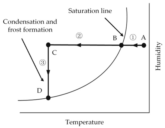
Figure 4.
The process of nucleation of water vapor around a cold surface [64].
In conclusion, the range of frosting map depends fundamentally on the air temperature and RH at the inlet of the outdoor air heat exchanger in the ASHP system. In other words, the task of studying frosting map for the ASHP system is to grasp accurately the various frosting conditions based on Ta-RH chart.
2.2.2. Ta-RH Frosting Map
According to the above analyses of both the three frosting pathways and the parameters describing frosting map, to solve the frosting problem and achieve the frost-free operation of the ASHP system, it is necessary to develop a Ta-RH frosting map indicating frosting situations and levels on the surface of an outdoor air heat exchanger [63].
Some investigations relating to developing the Ta-RH frosting map have been conducted by scholars in the world. As shown in Figure 5, Adachi et al. [68] pointed out that frosting conditions were as follows: (1) air temperature Ta was between −5 °C and 7 °C, and (2) air RH was between 60% and 100%. As shown in Figure 6, Jiang et al. [69] gave the fitting curves of RH with Ta based on the experimental data from Japanese scholars. The frosting region was confined to this range of air parameters in which RH was greater than 65% and air temperature Ta was between −12.8 °C and 5.8 °C. Using this frosting map, they analyzed the frosting characteristics of the ASHP system. And two new concepts, that is, index of frost quantity and index of relative frost quantity, were proposed [69]. Furthermore, Wang and Chen [70] developed a frosting map for the ASHP system using simulation data at an air velocity of 2 m/s (va), and the result is shown in Figure 7. As we can see, this frosting map includes three zones: a non-frosting zone (I), a condensing zone (II) and a frosting zone (III) [63]. The frosting zone III was confined between Ta of −10 °C and 8 °C and between RH of 63% and 100%. According to different frosting rates (Wm), this region III was further divided into five regions to present more details [63].
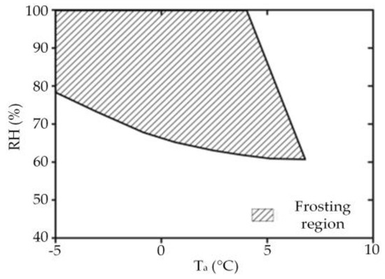
Figure 5.
Frosting map developed by Adachi et al. [68].
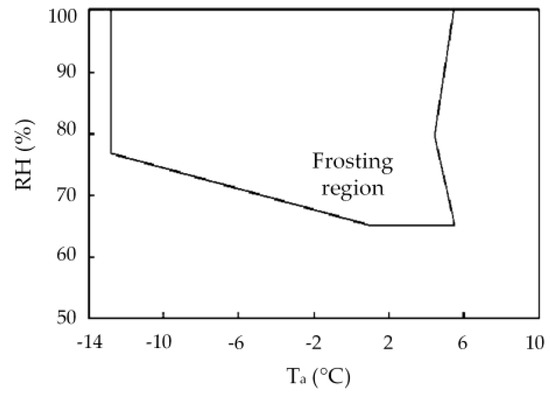
Figure 6.
Frosting map given by Jiang et al. [69].
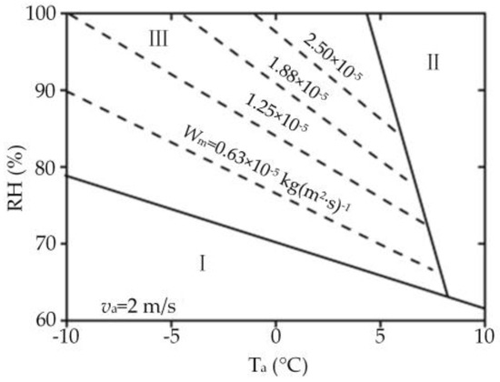
Figure 7.
Frosting map proposed by Wang and Chen [70].
However, these frosting maps above cannot be used to specify the level of frosting and as a base for the FFASHP system control. Because they were not verified by field test. Feng [71] suggested that when the outdoor air temperature was between −0.6 °C and 1.6 °C and its RH was 45% and 52%, frost formation may also happen on the air heat exchanger surface. But this range is not covered in frosting region of Figure 5, Figure 6 and Figure 7.
To further improve the frosting map, Zhu et al. [63] developed a new Ta-RH frosting map based on numerical results. As illustrated in Figure 8a, the new frosting map was divided into three regions, namely, a non-frosting region, a condensing region and a frosting region, by two boundary lines (a frosting line and a condensing line). Frost could occur on the heat exchanger surface if the air temperature was lower than the frosting line temperature (Ta < 6 °C) and its RH was above the condensing line (RH > 40–57.8%). When the RH was too high or the air temperature was too low, the ASHP system performance would decline significantly [63]. Thus, using the numerical data of frost growth, this frosting region was further divided into three indicative zones representing different frosting levels: a severe frosting zone, a moderate frosting zone (I, II) and a mild frosting zone (I, II), as shown in Figure 8b.
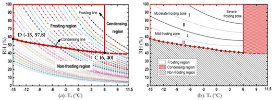
Figure 8.
A new frosting map developed by Zhu et al. [63]. (a) shows a new frosting map which was divided into three regions by a frosting line and a condensing line. (b) shows three frosting levels in frosting zone of the new frosting chart.
The correctness of these zones in Figure 8b were also verified by lab and filed tests [63,72]. Their operation conditions are listed in Table 2 and shown in Figure 9, and the corresponding results are shown in Figure 10. It can be seen that although frosting time was much shorter in severe frosting zone than that in other areas, the frost layers were significantly thicker in this zone (case 1–3) than that in the moderate region and the mild frosting region (case 5, 8, 11, 14) [63].
Table 2.
Operation conditions of all test cases [63].
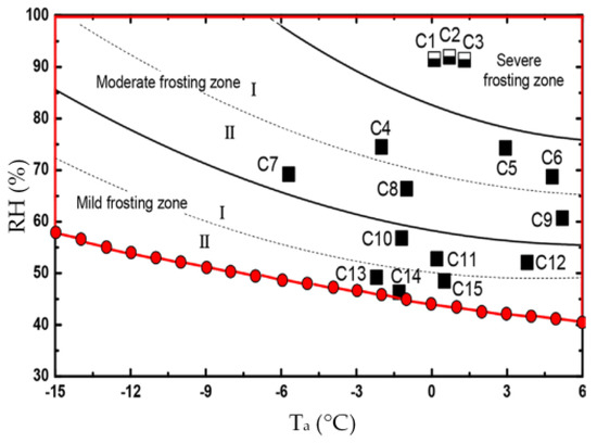
Figure 9.
Test conditions shown on the frosting zone in frosting map for case 1–15 [63].
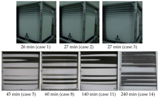
Figure 10.
Results of laboratory (Case 1–3) and selected field (Case 5, 8, 11, 14) tests [63].
In addition, based on the severe frosting region in Figure 8b and Figure 9, Su and Zhang [73] proposed the suggested operation region, as shown in Figure 11. Furthermore, the inefficient region (−9.5 °C < Ta < 6 °C and RH > 90%) is also given in Figure 11. The COPsen of the ASHP system was less than 2 in the inefficient region. Although the new frosting map provided by Zhu et al. [63] had been verified by some experiments and field tests, it still existed shortage. According to the previous results [74], when the ASHP system was operated in Beijing at the air temperature of −10 °C to 8 °C and RH of 29% to 40%, frost also may occur on the outdoor air heat exchanger surface, as shown in Figure 12. This air parameter range is not covered in the frosting regions of Figure 8, Figure 9 and Figure 11. Therefore, the frosting map still need to be further studied in a wider range of environments.
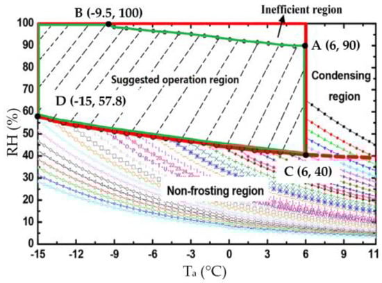
Figure 11.
The suggested operation region of the proposed system [73].
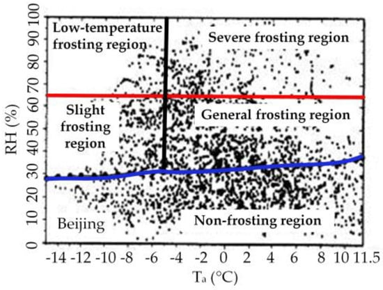
Figure 12.
Distribution of air parameters during heating season in Beijing [74].
3. Characteristics of Different Frost-Free Technologies
To solve frosting problem for the ASHP system, a new technology has been studied to prevent frost layer from forming on the outdoor air heat exchanger surface, and that is the so-called frost-free technology for the ASHP system. This technology can realize the frost-free operation of the ASHP system in the frosting region via adding a dehumidification system to decrease phase change driving force.
The common air dehumidification technologies include solution dehumidification [75], solid dehumidification [76], heating ventilating air conditioning dehumidification [77], membrane-based air dehumidification [78], cooling dehumidification and waste heat recovery. Among them, the solution dehumidification [79] and the solid dehumidification [80] were mainly applied to realize the frost-free operation of the ASHP system. In addition, the exhaust air heat recovery was also used to study the frost-free technology of the ASHP system, and the experiment proved that this system could keep the evaporator frost-free at the air temperature of −20 °C [81]. Because this frost-free technology is currently published in one article, we do not make detailed analysis in this paper.
In recent years, many researchers focus primarily on the investigation of following two FFASHP system: (1) integrated with a liquid desiccant device; (2) coupled a solid desiccant-coated heat exchanger. As seen in Table 3, among both them, the former is usually used for a FFASHP heating system, and the latter was used for a FFASHP water heater system. In this section, the characteristics of two frost-free technologies are mainly summarized and presented.
Table 3.
Type of frost-free air-source heat pump (FFASHP) system based on liquid/solid desiccant.
3.1. Frost-Free Technology for an ASHP Heating System
3.1.1. FFASHP Heating System Description
(1) Main components of system
Figure 13 indicates schematic diagrams of two FFASHP heating systems based on the liquid dehumidification method. As we can see from Figure 13, the FFASHP heating system based on method 1 consists of a conventional ASHP subsystem, a solution spray subsystem and a solution regeneration subsystem. Another FFASHP heating system based on method 2 consists of a conventional ASHP subsystem, an air pre-dehumidification subsystem and a solution regeneration subsystem. Three subsystems in the above two FFASHP heating system contain the following components: evaporator, condenser, expansion valve, compressor, four-way valve, solution pump, sprinkler, solution tank or dehumidifier and regenerator. It should be noted that Figure 13 only gives simple schematic diagrams of the systems and their detailed structures can be referred to the relevant references [79,84,87].
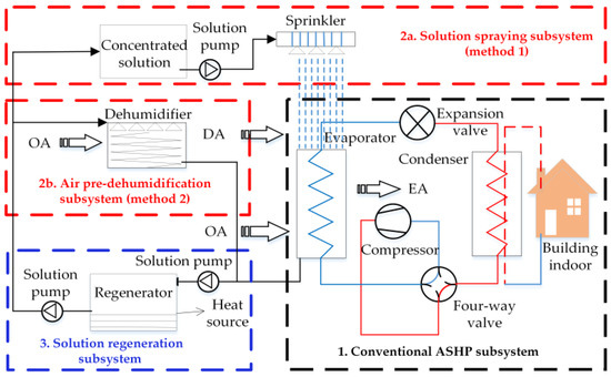
Figure 13.
Schematic diagram of FFASHP heating systems based on liquid desiccant.
(2) Main parameters
For the FFASHP heating system based on method 1, the parameters of the test room and main components are listed in Table 4. To simulate a frosting environment, an air conditioner, a heater and three humidifiers were used to adjust the air parameters of the test room. The heating and cooling capacities of the air conditioner were 3.5 kW and 2.5 kW, respectively [79]. Through keeping constant frosting environment and indoor environment, the experiments were carried out by Jiang et al. [79] under the operation conditions shown in Table 5.
Table 4.
Parameters of main devices [79].
Table 5.
Values of experimental parameters [79].
For the FFASHP heating system based on method 2, the solution, the main components, the indoor and outdoor environment parameters in different studies are listed in Table 6 and Table 7. Table 6 shows the parameters of numerical calculation of Zhang et al. [84]. Table 7 summarizes the analysis calculation and design parameters when Su et al. [73,87] and Yongcun et al. [53] analyzed the performance of this FFASHP heating system. And it also give the analysis parameters for a 150 m2 apartment (keeping indoor temperature of 20 °C and humidity of 8.7 g/kg) [82]. The thermodynamic properties of liquid desiccant solution can be calculated and obtained according to the formulas in literatures [88,89,90].
Table 6.
Parameters of the analysis calculation [84].
Table 7.
Values for the analyzed parameters in different studies.
(3) Operation process of system
During heating mode, the solution spray subsystem was closed in the FFASHP heating system based on method 1, when the outdoor ambient air temperature and RH were in the non-frosting area. On the contrary, when the outdoor environments were in the frosting area, the solution spray subsystem was operated, and the low freezing point solution was sprayed onto the air heat exchanger in the form of liquid films and liquid droplets [79]. The outdoor air (OA) flowed into the air heat exchanger and was dehumidified by contacting the liquid films and the liquid droplets to decrease the dew point temperature, while the heat from the air was absorbed by the solution. And then the heat was released to the evaporator [53,91]. Thereby, two essential elements of frosting were avoided. This kind of FFASHP system will has a good prospect because its simple dehumidification component and relatively low manufacturing cost. And thus, in the Section 5 of the present paper, the exergy and economic analysis of this frost-free system will be conducted.
As a result of the application of the solution spray subsystem, the gas-solid-liquid heat transfer mode of outdoor air heat exchanger in the ASHP system is replaced by another heat transfer mode, which mainly depends on the coupled heat transfer of gas-liquid-solid-liquid composed of air, solution, fin and refrigerant, as shown in Figure 14. It is common knowledge that the heat transfer coefficient of this new heat transfer mode is higher than that of the gas-solid-liquid heat transfer mode. However, if the liquid film of solution on the surface of heat exchanger is too thick, the air flow resistance and the thermal resistance between the air and the heat exchanger will increase, resulting in the system COP to decrease. Therefore, it is necessary to study the heat transfer enhancement technology of the gas-liquid-solid multiphase heat transfer process on the surface of the air-side fin-tube heat exchanger under the solution spray working condition.
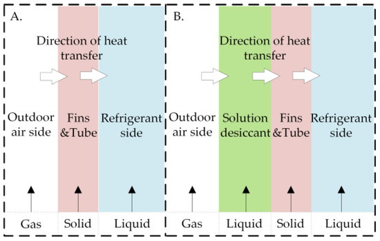
Figure 14.
Schematic diagrams of two heat transfer modes.
For another FFASHP heating system based on an air pre-dehumidification subsystem [84,87] shown in Figure 13, when the ambient air temperature and RH were in the frosting region, the air pre-dehumidification subsystem was opened, the outdoor air (OA) firstly passed through a dehumidifier to reduce the moisture content of the outdoor air and decreased the dew point of the air. Afterwards, the dry air (DA) flowed into the air heat exchanger to heat and evaporate the refrigerant in tube, and there was no frost on the air heat exchanger surface [84].
Furthermore, for two FFASHP heating systems above, with increasing the moisture content of the liquid desiccant solution, the vapor partial pressure of the liquid desiccant is higher than that of the outdoor air, causing the decrease of its dehumidifying performance. Thus, to keep the continuous frost-free operation of the FFASHP heating system, the liquid desiccant solution should be regenerated in time.
3.1.2. Regeneration of Liquid Desiccant
Using renewable energy or waste heat to regenerate the desiccant material can not only improve the COP of ASHP system but reduce its operation cost. According to the published references, the regeneration methods of liquid desiccant were as follows: vapor compression system, electrical heater, waste heat, solar energy, ultrasonic and electro-osmosis [92].
In these methods above, some have been used for regenerating the liquid desiccant to maintain continuous frost-free operation of the FFASHP systems. For example, Jiang et al. [79] proposed using the condensation heat of refrigerant in summer to regenerate the spray solution. But this method led to the higher costs of investment and operation because a large amount of dehumidifying solution and large volume solution storage tanks were needed. Consequently, the application of this seasonal regeneration method is not recommended.
Zhang et al. [82] utilized the vapor compression system to preheat the liquid desiccant before entering the regenerator and then fresh air flowed into the regenerator to be humidified by contact with hot liquid desiccant. Finally, the concentrated liquid desiccant was obtained. Yongcun et al. [53] designed a multi-stage regenerator to improve the regeneration effectiveness. Although both the regeneration methods can increase the driving force of heat and mass transfer between the solution and the air while improving regeneration efficiency, these systems are more complicated. It will decrease the operation reliability of the system. Therefore, a simple and efficient regeneration method of the liquid desiccant should be explored in the future.
3.1.3. Liquid Desiccant
The characteristics of solution desiccant are crucial for the FFASHP heating system. Currently, the available dehumidifying solutions could be mainly classified into three categories [79,93,94]: (1) organic solution (diethylene glycol, triethylene glycol, glycerol); (2) inorganic salt solution (LiCl, LiBr, CaCl2); and (3) acid solution (H2SO4 and H3PO4). The characteristics of these solution desiccants are listed in Table 8. It can be seen from the Table 8 that two acid solutions are not suitable for the FFASHP system due to its strong toxicity and corrosivity. And the corrosivities of the organic solution desiccants on metal materials are lower than that of other solutions.
Table 8.
The characteristics of common liquid desiccants [93].
Through comparing to the properties of various solutions, Jiang et al. [79] found that the glycerol aqueous solution was suitable as a spray solution for the frost-free system. As shown in Figure 15, the concentration of glycerol aqueous solution should be below 80%. This main reason was that the viscosity of glycerol solution increased sharply when the concentration was over 80%. We also could see when the concentration of the solution was lower than 30%, its corresponding freezing point was too high so that dehumidifying capability was lost [79]. As a result, the concentration of the glycerol solution selected was between 30% and 70% [79,95]. Even so, the glycerol aqueous solution was not optimum liquid desiccant for the frost-free technology of the ASHP system, because the energy consumption of its regeneration was high [95].
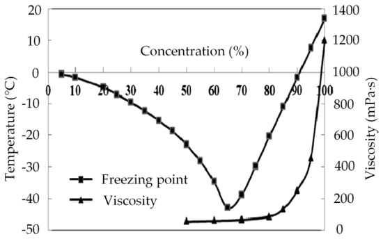
Figure 15.
The freezing point and viscosity of glycerol solution at different concentrations [79].
Compared with the LiBr aqueous solution, the dehumidification capacity of LiCl aqueous solution was 20% higher than that under the same working condition. And the power consumption of pump can be 20% lower than it [96]. As a result, LiCl solution was generally chosen by scholars as a desiccant for FFASHP system. For example, Su et al. [73] and Zhang et al. [82,84] selected the lithium chloride aqueous solution to dehumidify the moist air before it entered the heat exchanger. In order to avoid the crystallization of the selected solution in the temperature range of the system operation, the solution concentration should be 25–45% [95]. And the regeneration temperature was low within this concentration range, which can make better use of low-temperature heat source [94]. However, the lithium chloride solution also cannot be used as the best desiccant to be recommended in FFASHP technology in the future because of its high price.
3.2. Frost-Free Technology for an ASHP Water Heater System
3.2.1. FFASHP Water Heater System Description
The FFASHP water heater system coupled a solid desiccant is generally composed of a conventional ASHP subsystem, a desiccant-coated heat exchanger [83] or an extra heat exchanger coated by a solid desiccant with an energy storage device (EHECSD) [10,80]. The systems could not only prevent frosting in heating mode but supply uninterrupted heating in regeneration mode. It should be noted that the solid desiccant and the extra heat exchanger should be integrated [80].
A schematic diagram of the FFASHP water heater system coupled a desiccant-coated heat exchanger is illustrated in Figure 16. It mainly consists of a solid desiccant-coated heat exchanger, an air heat exchanger, a compressor, a water heat exchanger, a water tank. The parameters of the numerical calculation based on this system are listed in Table 9.
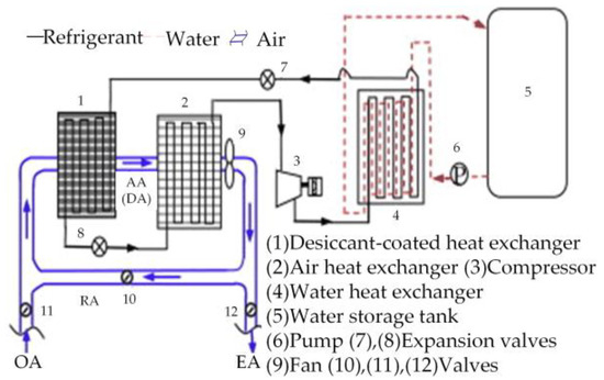
Figure 16.
Schematic diagram of the FFASHP water heater system based on solid desiccant [83].
Table 9.
Parameters of the numerical calculation [83].
In heating mode, the valves (11, 12) were opened and the valve (10) was closed. The extra heat exchanger coated by the solid desiccant in this system could dehumidify the outdoor air before entering the air heat exchanger, so that the dew point of the air entering the heat exchanger was decreased. Thus the frost-free operation of the system could be realized [83].
With increasing moisture content of the solid desiccant, the vapor partial pressure of the desiccant was higher than that of the outdoor air and thus the system was switched to the regeneration mode. During regeneration mode, the valve (10) was opened and the valves (11, 12) were closed. The refrigerant was discharged from the compressor and passed through the water tank, flowed through the desiccant-coated heat exchanger to heat the air and to regenerate the desiccant. And then the refrigerant was throttled by the expansion valve (8), entered the air heat exchanger and was vaporized by hot and humid air [83].
As shown in Figure 17, the FFASHP water heater system combined with energy storage and dehumidification technology consists mainly of a compressor, a four-way valve, a water tank, an energy storage device (ESD), three electronic expansion valves (EEVs), an extra heat exchanger coated by a solid desiccant (EHECSD) and an outdoor air heat exchanger [10,80,85]. The structural parameters of EHECSD and ESD, and the main characteristics of the measuring instrumentation are listed in Table 10 and Table 11, respectively. For this FFASHP water heater system, the operation conditions in different studies are summarized in Table 12.
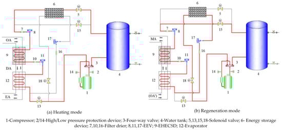
Figure 17.
The FFASHP water heater system combined with solid desiccant and energy storage [52].
Table 10.
The structural parameters of extra heat exchanger coated by a solid desiccant with an energy storage device (EHECSD) and energy storage device (ESD) [10].
Table 11.
Main characteristics of the measuring instrumentation [10,80].
Table 12.
Operation conditions for the experimental FFASHP water heater system.
As we can see from Figure 17a, in heating mode, the refrigerant passed through the four-way valve after being discharged from the compressor, flowed into the condenser and then run through the ESD where the condensation heat was absorbed. Afterwards, it was throttled by the EEV (8), entered the EHECSD in which the refrigerant absorbed latent heat released by water vapor from the air, and flowed into the evaporator. The dew point of the air was decreased, and thus the frost-free operation was realized [85].
Figure 17b describes that in regeneration mode, the refrigerant was discharged from the compressor and passed through the four-way valve and the water tank, flows through the EHECSD, entered the evaporator, was throttled by the EEV (17), and then flowed through the ESD, finally returned the compressor to complete the regeneration process [10]. In the period of regeneration cycle, the outdoor air was firstly preheated in the evaporator and then flowed through the EHECSD while the water vapor from the solid desiccant was removed [10,80].
3.2.2. Solid Desiccant
Commonly used solid desiccant materials in drying applications included the conventional physical desiccant (e.g., silica gel, molecular sieve and activated carbon) [97] and the new compound desiccant consisting of physical and chemical desiccant (e.g., silica gel based composite desiccant, molecular sieve based composite desiccant and carbon based composite desiccant) [98]. According to the references [80,83], the silica gel or silica gel based composite desiccant was usually used to dehumidify the outdoor air to realize frost-free operation of ASHP systems. This is because it is of great specific surface area (about 530 m2/g) and good moisture adsorption capacity [99].
As summarized in Table 2, the solid desiccant was primarily applied to realize the frost-free operation of the ASHP water heater system and not used for the FFASHP heating system. This is due to the following three reasons: (1) a liquid desiccant system can be driven by low-temperature heat source in comparison with solid desiccant [100]; (2) the power of ASHP heating system is larger than that of ASHP water heater system, that means a large demand for desiccant in the heating system; and (3) the price of the solid desiccant is more expensive in comparison with the liquid desiccant, resulting in increasing the cost of ASHP system.
4. Performances of Two Types of FFASHP Systems
4.1. Performance Indexes
When the ASHP system is in steady state, the energy loss and flow loss of the working fluid can be neglected. According to the first law of thermodynamics, the performance of the ASHP system is usually evaluated by the primary energy ratio (PER) and the coefficient of performance (COP). The former refers to the ratio of heating capacity (Q, kW) of the system to the primary energy consumed by the compressor. The PER can be concluded as Equation (2).
where, ηεy is the power supply efficiency of the power plant, 35%; Wcom is the amount of electrical power consumption of compressor, kJ.
The COP is defined as the ratio of the heating capacity Q to the amount of electrical power consumption of compressor Wcom. It is calculated using Equation (3). By comparing Equation (2) with Equation (3), we can find that the PER of an ASHP system is 0.35 times as many as its COP. This means that the evaluation results of PER and COP are equivalent. In this paper, the COP is used as the performance index of the FFASHP system.
Table 13 summarizes the expressions of the COP of the FFASHP system in different literature. Although the forms are different from that of Equation (3), their physical meanings are completely consistent. In addition, in Table 13, the No. 6 formula is a fitting correlation of the COP with the mass of solid desiccant (x, kg) and the volume of PCM (y, mL). And the values of the coefficients (from C0 to C9) used in No. 6 formula are presented in Table 14.
Table 13.
The calculation expression of COP of various FFASHP systems.
Table 14.
The values of the coefficients in No. 6 formula in Table 13 [52].
In this section, the performances of the different FFASHP systems proposed in the references are reviewed. And the performance comparisons between the FFASHP systems (including the FFASHP heating system and the FFASHP water heater system) and the conventional ASHP system are also presented.
4.2. Performance of the FFASHP Heating System
4.2.1. Effects of Outdoor Air Parameters on FFASHP Heating System Performance
As we all know, the outdoor ambient air temperature and RH have significant influence on the performance of the conventional ASHP system. And thus, effects of both them on the performances of the FFASHP systems also cannot be ignored.
According to the references, the effects of air temperature and RH on the performance of the FFASHP heating system have been extensively studied by scholars under keeping the other parameters constant. Su and Zhang [73] indicated that the COPtotal of the FFASHP heating system increased significantly from 2.40 to 3.81 (increased by about 59%) with the increase of the air temperature from −30 °C to 0 °C, as shown in Figure 18. The COPtotal increased slightly from 3.82 to 3.87 with increasing the RH from 65% to 85%. Meanwhile, the simulation results of Zhang et al. [82] showed that the COPtotal of the FFASHP heating system increased by about 90% as the air temperature increased from −7 °C to 11 °C and at constant RH (50% and 70%). When the RH increased from 50% to 70%, the COPtotal only increased by about 10%. Su et al. [87] also pointed out that the system COPaverage increased by about 15.3% when the air temperature increased from −10 °C to 0 °C and at the RH of 80%. And it declined slightly by 2.59% with the RH rising from 70% to 90% at 0 °C.
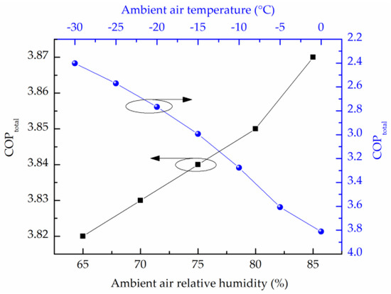
Figure 18.
Effects of the ambient air temperature and its relative humidity on the total coefficient of performance (COPtotal) of FFASHP system [73].
In addition, through changing the air temperature and RH only, Yongcun et al. [53] established a theoretical model and analyzed the system COP at different condensing temperatures (Tc = 40 °C, 45 °C and 50 °C). The results as Figure 19 shows. It can be seen from Figure 19a that the system COP increased significantly as the air temperature increased at different condensing temperatures. The change trend was similar to the result provided by Zhang et al. [82]. From Figure 19b, it can be clearly seen that the RH had a slightly effect on the COP. The reason was that the humidity ratio was low at high RH in winter so that solution could absorb less water vapor from the air [53]. Besides, Figure 19 also showed the system COP increased significantly with increasing the condensing temperature at different air parameters.
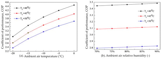
Figure 19.
Effects of ambient air temperature and its RH on COP of FFASHP system [53].
From these results, we can clearly see that the effect of the ambient air temperature on the COP of the FFASHP heating system is more significant in comparison with the air RH. This revealed that the higher the ambient air temperature was, the more the heat extracted by the system from the environment was [53]. Although the COP reduced significantly with decreasing air temperature, the system still operated at a COP being more than 2.3 for the cases that the air temperature ranges from −20 °C to −30 °C [53,73]. Furthermore, the solution can absorb more water from the air when the air humidity increases at constant temperature. This means that more latent heat must be extracted by the solution. That is the reason why the COP increases slightly with increasing air RH [73].
4.2.2. Effect of Solution Concentration on FFASHP Heating System Performance
Besides the outdoor air temperature and its RH, the effect of the solution concentration on the COP of the FFASHP heating system is also important. And limited studies related to the effect of the desiccant solution concentration on the system COP have been previously reported. For example, the experimental results of Jing et al. [79] showed that the COP of spray time increased firstly with the increase of the glycerol solution concentration and then decreased slowly. The total COP change law of the system was not known. It was mainly caused by smaller solution concentration made it in danger of freezing, larger concentration consumed more pump power in the process of transportation due to the larger viscosity. Finally, this study pointed out that the best concentration of glycerol solution for preventing frost formation was 50% [79].
Yongcun et al. [53] showed that the COP of the FFASHP system increased by about 6% with the increase of inlet lithium chloride solution mass fraction from 20% to 40% in solution tower. Zhang et al. [84] also indicated that as the lithium chloride solution concentration increased from 34% to 37%, the COPtotal of the FFASHP system increased by about 10%, as shown in Figure 20. Increasing the concentration of solution made drive force of mass transfer enhance, that means the solution could absorb more heat released by water vapor, so the system COP increased [53]. However, the concentration should be not higher than 37.5%. Because the crystallization of the high concentration lithium chloride solution at below −10 °C results in losing the dehumidification capacity [84].
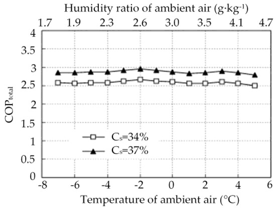
Figure 20.
Effect of lithium chloride solution concentration on COPtotal [84].
Therefore, to improve the COP of the FFASHP system, the dehumidification capacity of solution desiccant, the crystallization and the viscosity with temperature should be taken in account in selecting the concentration of solution desiccant. In other words, the too large or too small concentration of desiccant solution will lead to a decrease in the COP of the FFASHP heating system.
4.2.3. Effects of Other Parameters on FFASHP Heating System Performance
Air-to-solution mass flow rate ratio, the inlet solution temperature and the solution mass flow rate have unignored effects on the COP of the FFASHP heating system [53,73,79,87]. Su and Zhang [73] showed that when the air-to-solution mass flow rate ratio in the regenerator and the dehumidifier varied respectively from 1.0 to 2.5 and 2.0 to 3.5, the COPtotal of the FFASHP heating system could be improved. According to the results of Su et al. [87], the COPaverage of the FFASHP system firstly increased gradually, reached the highest point and then decreased with the increase of air-to-solution mass flow rate ratio from 1.5 to 3.5 in the dehumidifier, as shown in Figure 21. This could be explained as follows: (1) the evaporation temperature will be improved by increasing flow rate, thereby the COP increased; (2) the following decrease of the COP resulted from the increase of both pump power and regenerative power caused by increasing air flow rate [87].
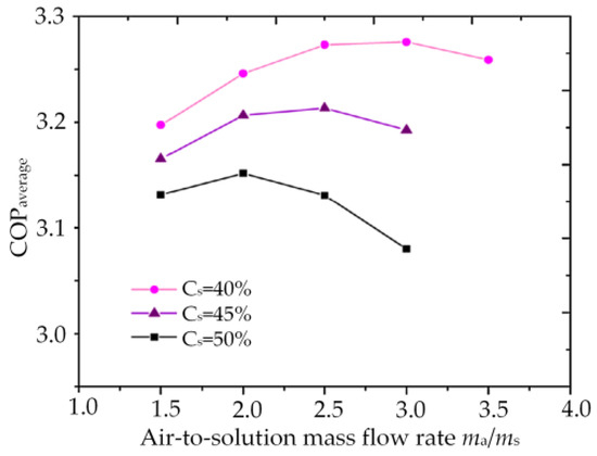
Figure 21.
Effects of air-to-solution mass flow rate on the COPaverage of FFASHP system at different concentrations [87].
In addition, according to the report of Yongcun et al. [53], the COP of the FFASHP heating system increased quickly and then declined with the increase of the inlet solution temperature in solution tower, as shown in Figure 22. This was because the humidity ratio and the temperature of ambient air was low in winter, and the change of the COP depended mainly on the inlet solution temperature in solution tower. However, the vapor pressure of solution rose as the inlet solution temperature increased and the drive force of heat and mass transfer was decreased, that means the solution could absorb less heat from air.
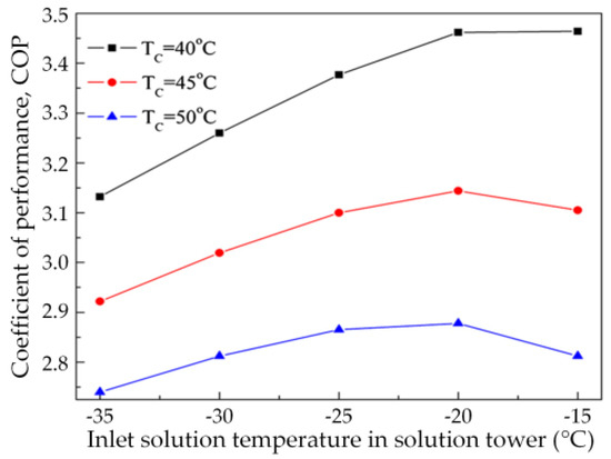
Figure 22.
Effect of the temperature of inlet solution in solution tower on COP of FFASHP system [53].
The experimental results of Jing et al. [79] showed that as the flow rate of spray solution increased, the COPtotal of the FFASHP system firstly increased and then decreased. When the flow rate was 287 kg/h, the COPtotal reached the highest point at 3.046. When the flow rate was over 287 kg/h, the system COP decreased due to the increases of the power consumption of pump, the flow resistance and the thermal resistance.
As a result, like the concentration of desiccant solution, air-to-solution mass flow rate ratio, the inlet solution temperature and the solution mass flow rate have optimum values making the COP of the FFASHP heating system reach maximum.
4.2.4. Comparisons of Performances of FFASHP Heating System and Conventional ASHP System
According to the literature, the COPtotal of the FFASHP system was significantly higher than that of traditional heat pump system integrated with an electric heater [82]. As shown in Figure 23, Zhang et al. [84] gave the comparison of the COP between the FFASHP heating system and traditional hot-gas defrosting heat pump integrated with an electric heater humidifying system. It can be found that the COPSHRU of the sensible heat removal unit was about 10% higher than that of the traditional system; the COPLHRU of the latent heat removal unit was 20–40% higher than that of the electric heater humidifier. As a consequence, the COPtotal of the FFASHP system was 30–40% higher than that of the traditional ASHP system integrated with an electric heater humidifying system [84]. Fan et al. [86] showed that the COP of the FFASHP system was 24–41% higher than that of traditional ASHP system using electric humidification at the outdoor air temperature of −4 °C to 5 °C and at the RH of 79%.
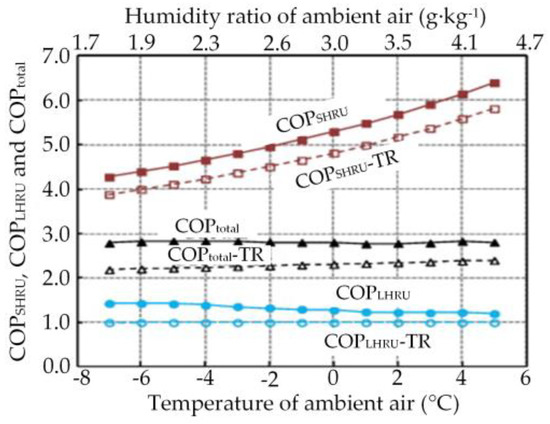
Figure 23.
Comparison of COPtotal between FFASHP system and tradition heat pump system [84].
Additionally, many researchers also showed that compared with conventional reversed-cycle defrosting ASHP system, the performance of the FFASHP system was significantly better. Based on the conditions in the reference [101], Yongcun et al. [53] studied the effects of air temperature and its RH on the COP of the FFASHP system and compared with that of conventional reversed-cycle defrosting ASHP system, and the results are shown in Figure 24. As can be seen, the FFASHP system COP was significantly higher than that of the conventional ASHP unit under the same parameters. And recent results provided by Su et al. [87] also showed a similar trend. Meanwhile, Su et al. [87] also indicated that the average COP of the FFASHP system was approximately 36–61% higher than that of conventional reversed-cycle defrosting ASHP system. And the total COP was approximately 64% higher than that of the conventional system [73].
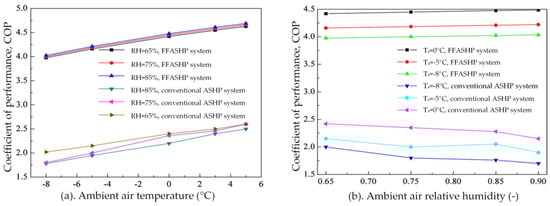
Figure 24.
Effects of ambient air temperature and RH on the COP of FFASHP and conventional ASHP [53].
In summary, compared with the different conventional ASHP systems, the COP of the FFASHP heating system is obviously higher. The main reason is that the FFASHP heating system can work continuously, and the defrosting mode needs not to be turned on periodically. As shown in Equation (4) [101], for the COP calculation of the conventional ASHP system, the actual heating capacity is significantly less than that of the frost-free system, and the actual electrical power consumption of compressor is obviously higher, so the COP of the conventional system is lower. In addition, it should be noted that in various literature studies, when calculating the COP of the HP system, the power consumption of the compressor is only considered, and the power consumptions of the fans, the solution pumps and the water pumps are neglected. This may also lead to a higher difference of the COP between the conventional ASHP unit and the FFASHP unit.
where, Qheasting and Qdefrosting are the heating capacity and defrosting capacity of the system, respectively, kW. Wcom,heating and Wcom,defrosting are the power consumption of the system in heating period and defrosting period, respectively, kW.
Although the COP of the frost-free heating system is high, the added liquid desiccant subsystem and regeneration subsystem not only increases the investment cost and the floor space of the system, but results in the initial system more complex which decreases the system operation reliability. The spreading application of the FFASHP heating system is limited by these practical problems. Therefore, a simple and efficient FFASHP heating system coupled with air dehumidification and liquid desiccant regeneration should be developed. Besides, it is very necessary to explore a new frost-free technology of the ASHP system without adding any desiccant device.
4.3. Performance of the FFASHP Water Heater System
4.3.1. Effects of Outdoor Air Parameters on FFASHP Water Heater System Performance
Based on the two FFASHP water heater systems in Figure 16 and Figure 17, Zhang et al. [83] and Wang et al. [10,85] showed that the COPs of two systems increased with increasing the ambient air temperature for any RH. When the air temperature increased from −7 °C to 5.5 °C and at the RH of 60%, the COP of the FFASHP water heater system in Figure 16 increased from 3.6 to 4.4 (increased by 22.2%). With the increase of the air RH at different air temperature, the system COP declined significantly due to the sensible heat factor (SHFad) rising with increasing the RH [83]. When the RH was 80%, the COP only increased by 6.7% with increasing the temperature, that means under a higher air RH, the ambient air temperature had a slight effect on the system COP. However, the frosting could not be completely avoided in the whole operation process. Because the moisture from the desiccant-coated heat exchanger could still result in frosting on the surface of the evaporator in regeneration mode when the temperature of the refrigerant was below 0 °C.
For the FFASHP water heater system coupled an extra heat exchanger coated by a solid desiccant with an energy storage device in Figure 17, the air heat exchanger could be kept frost-free for 32, 34, 36 min during heating mode at the outdoor air temperature of −3 °C, 0 °C and 3 °C and RH of 85% [10]. And when the air temperature increased from −10 °C to 5 °C at the RH of 85%, the system average COP increased from 2.4 to 3.2 (increases by 33.3%) [85]. This system could not only prevent frosting in heating mode, but also avoid frost formation in regeneration mode.
From these results, we can see that the performance of the FFASHP water heater system is not reported at a lower air temperature (e.g., from −30 °C to −11 °C). This may be because the adsorption capacity of solid desiccant in lower temperature regions is limited. Therefore, the application of the FFASHP water heater system has not been promoted in the cold regions of China. In the future, the ASHP hot water units based on waste heat recovery technology should be studied and popularized.
4.3.2. Effects of the Amount of Desiccant and PCM on FFASHP Water Heater System Performance
The solid desiccant mass and the volume of phase change material (PCM) had significant effects on the COP of the FFASHP water heater system [52]. As shown in Figure 25, the maximum value of the system COP was 2.99 at the air temperature of 0 °C and RH of 80%, at which time the amount of the desiccant and the PCM were 2.2 kg and 800 mL, respectively. However, the simulation result showed that the temperature of the water in water tank was only 49.8 °C in this case. The further analysis of Wang et al. [52] indicated that when the mass of desiccant was 2.2 kg, the volume of PCM is 1100 mL, the water temperature could reach 55 °C and the COP of the FFASHP water heater system was 2.87.
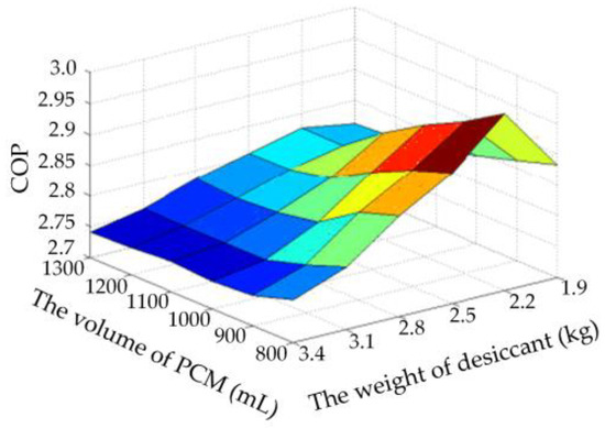
Figure 25.
Effects of the amount of desiccant and phase change material (PCM) on the COP of FFASHP water heater system [52].
In order to predict the system performance though the desiccant mass and the volume of PCM, the correlation of the COP was proposed based on the weight of the solid desiccant and the volume of the PCM [52]. The correlation Equation (No. 6) is listed in Table 13 and its coefficients (from C0 to C9) are summarized in Table 14.
As a result, when a FFASHP water heater system is designed and optimized, we should not only consider the correlation of the system COP with both the desiccant mass and the volume of PCM, but also pay close attention to whether the water temperature meets the requirement.
4.3.3. Performances of FFASHP Water Heater System Using Different Refrigerants
Based on the FFASHP water heater system in the reference [80] (Figure 17), Wang et al. [10,85] studied the performance of the FFASHP water heater system using different types of refrigerants (R22, R407C and R134a) via experimental and numerical method, respectively. And the thermo-physical properties of R22, R407C and R134a are listed in Table 15. As shown in Table 15, the environmental characteristics of R134a are better in comparison with R22 and R407C.
Table 15.
Thermo-physical properties of R22, R407C and R134a [85].
The experimental data indicated that when the refrigerant was R134a, the air heat exchanger could be kept frost-free for 34 min during heating mode at the air temperature of 0 °C and RH of 85%. And the system COP increased by 45.5% with increasing the temperature from −3 °C to 3 °C [10]. The simulation results of Wang et al. [85] showed that the time for keeping the air-side heat exchanger frost-free operation for R22, R407C and R134a could up to 29, 34 and 35 min, respectively. As shown in Figure 26, the COP for R134a was 3.3% and 8.6% higher respectively that of that for R22 and R407C at the ambient temperature of -10 °C and RH of 85% [85]. Therefore, R134a is more suitable for the FFASHP water heater system at low-temperature in comparison with R22 and R407C. In addition, considering that R22 will be abolished in the developing countries by 2030 due to environmental problems relating to ozone depression potential and global warming potential, the COP of the FFASHP system using the alternative refrigerant R134a should be further studied. In the future, the frost-free technology of the ASHP unit using CO2 and R290 as working fluids should be also studied.
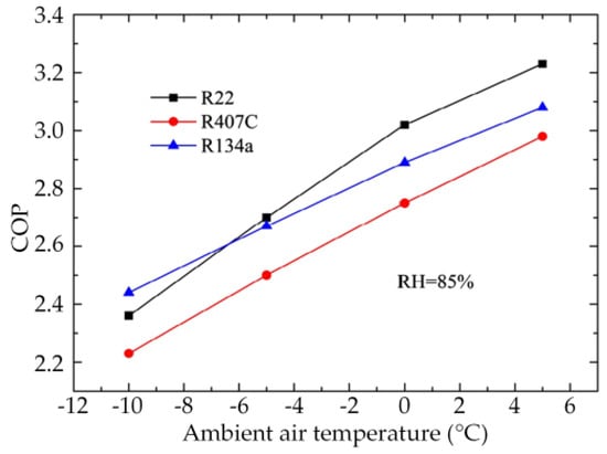
Figure 26.
Effects of ambient air temperature on the COP of the FFASHP water heater system with three different refrigerants [85].
4.3.4. Comparisons of Performances of FFASHP Water Heater System and Conventional ASHP System
Using the FFASHP water heater system integrated with the solid desiccant device in Figure 16, Zhang et al. [83] carried out a simulation study at the same temperature (from −7 °C to 5.5 °C) as the literature [84] and at the RH of 60–80%. The simulation results showed that the COP of the FFASHP water heater system was higher than that of the traditional hot gas defrosting ASHP water heater unit for any air temperature and its relative humidity [83], as shown in Figure 27. Compared with the hot gas defrosting ASHP water heater system, the COP of the FFASHP water heater system increased by 25–30% at the air temperature range of −7 °C to 6 °C and RH of 60%.
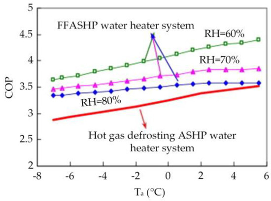
Figure 27.
Comparison of COP between the FFASHP water heater and the hot-gas defrosting ASHP water heater [83].
Compared with the conventional defrosting ASHP water heater system, the FFASHP water heater system coupled an extra heat exchanger coated by a solid desiccant (EHECSD) with an energy storage device (ESD) (Figure 17) was also of better performance. Wang et al. [80] studied experimentally the performance of this kind of FFASHP water heater system. The experimental results showed that the outdoor evaporator could be kept frost-free for 34 min at the air temperature of 0 °C and RH of 80%. And comparing to the hot gas bypass defrosting and the electric resistance heating defrosting system, the average COP of the FFASHP water heater system increased by 7.25% and 46.3%, respectively.
As shown in Figure 28, Wang et al. [10] also pointed out that the COP of the FFASHP water heater system are 17.9%, 11.1% and 3.4% higher than that of the reverse-cycle defrosting ASHP system at the ambient air temperature of −3 °C, 0 °C and 3 °C, respectively. This revealed that when the RH was higher than 80%, the performance of the FFASHP water heater system was better at the low temperature than that at the high temperature.
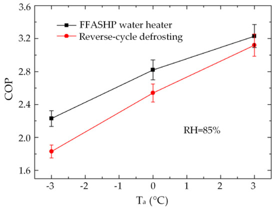
Figure 28.
Comparison of the COP between FFASHP water heater system and reverse-cycle defrosting system at different ambient air temperatures [10].
Like the FFASHP heating system, although the performances of the proposed FFASHP water heater systems are higher than that of conventional defrosting ASHP water heater system under various environmental conditions, the initial cost and the floor space of the system are also increased due to adding the solid desiccant facility and energy storage device. It is also because of the addition of these two devices that the complexities of system structure and control strategy are increased, leading to lower operation reliability of the whole system. Therefore, the promotion and application of this FFASHP water heater are limited in civilian domain. In addition, in the future, an ASHP unit integrating with space heating and hot water supply is more popular. The frost-free technology of this unit will be an important research topic.
5. Exergy and Economic Analysis of a FFASHP System
As described in Section 3.1, the FFASHP system based on solution spray will have a good application prospect in the future. Therefore, in this section, the exergy and economic analysis of this system are carried out in this section.
5.1. Exergy Analysis
The first law of thermodynamics (energy analysis) is the analysis of the quantity of energy. Compared to it, the second law of thermodynamics (exergy analysis) takes into account both of quality and quantity of energy and can provide more details of thermal process [102]. Therefore, according the second law of thermodynamics, the exergy balance equation of an ASHP system can be concluded as Equation (5).
where, Exin is the total exergy inputs of system, kW; Exout is the total exergy outputs of system, kW, Exloss is the total exergy loss rate of system, kW.
The total exergy loss rate of the ASHP system equals the sum of exergy loss of the main components. And thus, the total exergy loss rate on the right side of the equal sign in Equation (5) can be expressed as Equation (6).
where, Exloss,com, Exloss,evap, Exloss,cond, Exloss,expa are the exergy loss rates of compressor, evaporator, condenser and expansion valve, respectively, kW.
As shown in Table 16, some studies related to the exergy analysis of the HP system in heating mode showed that the exergy loss rates of the compressor and the evaporator account for the larger share of total exergy loss [102,103,104,105]. To reduce the exergy loss of the compressor, the following two measures should be carried out: (1) improving the manufacturing level of the compressor; (2) choosing the compressor with a smaller compression ratio. In this section, we mainly analyze the influence of frost layer on the exergy loss of evaporator.
Table 16.
The exergy loss coefficients or ratios of main components in different heat pump system.
It is common knowledge that the main factor affecting the exergy loss rate of the evaporator is the heat transfer temperature difference between refrigerant and ambient air. According heat transfer equation, the heat transfer temperature difference is proportional to the thermal resistance under a certain working condition. This means that the exergy loss rate of the evaporator increases with increasing the thermal resistance (see Equations (7) and (8) [102]).
where, mr is mass flow rate of the refrigerant, kg/s; hevap,in and hevap,out are specific enthalpy of the refrigerant on the inlet and outlet of the evaporator, respectively, kJ/kg; sevap,in and sevap,out are specific entropy of the refrigerant on the inlet and outlet of the evaporator, kJ/(kg·K); T0 is ambient temperature, °C; Te is evaporating temperature, °C; Qe is heat exchange quantity of the evaporator, kW; Q0 is total heat absorbed by the evaporator, kW; Raw is thermal resistance between wall and air, (m2·K)/kW; R0 is thermal resistance between wall and refrigerant, (m2·K)/kW.
When the ambient environment is in frosting region, frost will occur on the evaporator surface resulting in increasing the thermal resistance. Thus, the exergy loss rate of the evaporator increases (see Equations (9) and (10)). This shows that in winter, avoiding the operation of the ASHP under frosting conditions is an important way to reduce the exergy loss rate of the evaporator.
where, Raf is thermal resistance between air and frost (m2·K)/kW; Rf is thermal resistance of frost layer on the evaporator surface, (m2·K)/kW.
The FFASHP system is to reduce the exergy loss rate of the evaporator caused by environmental changes in winter through avoiding the necessary conditions for frosting. Especially for the FFASHP heating system based on solution spray method, when the ASHP unit is operated in the frosting region, the lithium chloride solution with a low freezing point is sprayed on the surface of the heat exchanger to absorb the sensible heat and the latent heat of the humid air, as shown in Figure 29. And then the thermal resistance is decreased. Thereby, the exergy efficiencies of the evaporator and the FFASHP system is improved.
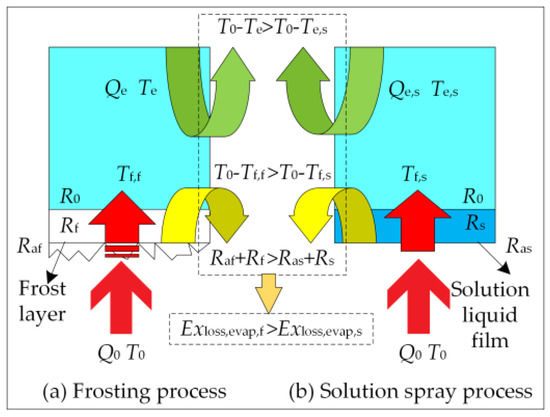
Figure 29.
Exergy loss analysis of the evaporator in frosting process and solution spray process. Where, Ras is thermal resistance between air and liquid film, (m2·K)/kW; Rs is thermal resistance of solution liquid film on the evaporator surface, (m2·K)/kW; Tf,f and Tf,s is temperature of the evaporator surface in frosting process and solution spray process, respectively, °C; Exloss,evap,f and Exloss,evap,s are exergy loss rate of the evaporator in frosting process and solution spray process, respectively, kW.
5.2. Economic Analysis
Through consulting literature materials, it can be confirmed that there is almost no the investment cost data related to FFASHP heating system in the published studies. Hence, in the present paper, a conventional ASHP unit is chosen for a subsystem to estimate the extra investment cost and its payback period of the FFASHP heating system. Table 17 shows the main design parameters of the conventional ASHP unit and the selected desiccant type.
Table 17.
Main parameters of the selected ASHP unit
5.2.1. Analysis of the System Cost
The initial investment of the conventional ASHP system includes generally equipment cost, installation cost, testing and commissioning cost, power distribution cost, control system cost and civil construction cost. In the FFASHP system, besides the above these costs, the initial investment cost of the system increases approximately by 5000 Chinese yuan (CNY) due to the added desiccant dehumidifying components/subsystem and regeneration subsystem.
The operation cost of the conventional ASHP unit mainly consists of equipment power consumption cost, maintenance cost, labor cost and equipment depreciation cost. Considering that the maintenance, labor and depreciation cost of the two systems are basically equal, and the share of three parts in the running cost is small, they are not calculated. For the power consumption cost of equipment, the FFASHP system is lower than the conventional ASHP system. It can be explained as follows: (1) electric power consumption of the fan increases in the growth process of frost layer; (2) a large amount of electric energy is used to defrost in the conventional ASHP unit. We mainly focus on the energy consumption in defrosting process without considering the energy consumption of the fan. This is because the fan power consumption account for less share in the whole ASHP system.
Based on the above analyses, the electric energy saved by the FFASHP system is equal to that consumed by the conventional system during defrosting process. The expense of this part of the electric energy is the main operation cost saved by the FFASHP system.
5.2.2. Payback Period of the Extra Investment Cost
According to the published literature [108], the efficiency (ηdefrost) of the typical defrosting method was generally in the range of 15–25%. It is taken as 20% in the analysis process of this paper. Assuming that the total heat energy per unit time provided by the system during defrosting is equal to the system heating capacity (Q), the effective heat energy in the defrosting process (Qef,defrost) equals the product of Q and ηdefrost, and the input power of the ASHP unit (p) is the power consumed by the system during defrosting (pdefrost). The defrosting time (tdefrost) should be less than or equal 20% of the total operation time a day [26]. It is taken as 8% in the section. Therefore, the operation cost during defrosting (Ydefrost) in one day can be calculated using Equation (11).
where, t is system operation time a day, 24 h; X is electricity price, 0.8469 CNY/(kW·h).
The payback period (PP) of the extra investment cost of FFASHP system equals 146.43 days (3514.32 h) obtained by Equation (12). This shows that the investment payback period of this frost-free technology is short.
6. Outlook for Future Research
Some studies related to the frost-free technology of ASHP system have been carried out by scholars. Various methods to address the problems relating to frosting conditions and solution regeneration have also been considered. Although the COP of the FFASHP system proposed in the references are demonstrated to be higher than that of the conventional ASHP system, there are still four important areas for the FFASHP system where the further study works are required.
- Optimization of system performance. To enhance the performance of the FFASHP system based on solution spray, it is necessary to study the heat transfer enhancement technology (e.g., forming thin and well-distributed liquid-film) of the gas-liquid-solid multiphase heat transfer process on the surface of the air-side fin-tube heat exchanger under spray condition. From the viewpoint of mass transfer enhancement, the change law of vapor partial pressure of desiccant solution with concentration should be further explored and studied at different low-temperature conditions in the future.
- New liquid/solid desiccant. A new desiccant, taking its cost, excellent dehumidification and regeneration performances into consideration, should be explored. For instance, a mixed liquid desiccant used to the FFASHP heating system should be studied and evaluated via the optimal ratio, cost and performances.
- New method. A new, simple and efficient frost-free technology of the ASHP system without adding liquid/solid desiccant device should be explored. This could be broken from the aspects as follows: improving structure of air-side heat exchanger, coupling with the solar energy, heat recovery of exhaust outdoor air and development and application of coating material.
- Optimization of system control strategy. The frosting map for the ASHP system should firstly be further improved based on considering climatic characteristics of key cities in China. And then combined with the new frosting map, the control strategy for the FFASHP system should be optimized for avoiding mal-opening and mal-closing of desiccant dehumidification subsystem to decrease the system performance.
7. Conclusions
Besides defrosting and anti-frosting methods, the frost-free technology is also a must for the development and application of an ASHP system. This study firstly analyzed the frosting pathway based on phase diagram of water, summarized the investigation of Ta-RH frosting map, and then reviewed and presented the characteristics of frost-free technology and the performances of the FFASHP systems. Followed by analyzing the exergy loss rate of the evaporator in the FFASHP system integrated with solution spray and estimating the extra investment cost of the system together with the corresponding payback period. Finally, some unsolved problems and potential gaps were given from optimization of the system performance, new liquid/solid desiccant, new method and optimization of the control strategy. The main conclusions drawn from this literature review can be summarized as follows:
- Theoretically, there are three pathways of frost formation as follows: gas-liquid-solid, direct gas-solid, and occurring simultaneously. The frosting processes of the different phase changes may be avoided through changing the air temperature or water vapor pressure. In addition, to make the frosting map use directly a base for solution system control in FFASHP system integrated with solution spray, it should be improved in a more extensive frosting environment in the future.
- Compared with air RH, the effect of air temperature on the COP of the FFASHP system is more significant. The total COP of the FFASHP heating system is 30–64% higher than that of the conventional ASHP system under the low temperature conditions. The COP of the FFASHP water heater system is also affected by the amount of desiccant and PCM. In the future, the frost-free technology of an ASHP unit integrating with space heating and hot water supply will be an important research topic.
- Though the FFASHP systems can achieve the frost-free operation under frosting conditions, the initial investment cost and the floor space of the systems increase. Currently, the FFASHP systems are basically in the theoretical and experimental research stage, and have not yet realized industrial application. The reliability of long-term operation needs further field test in the future. In addition, the regeneration method of liquid desiccant is also a barrier for the popularization of the system.
- Under frosting conditions, a liquid film with low thermal resistance and low freezing point is sprayed onto the surface of the evaporator in ASHP system, reducing the heat transfer temperature difference. Thereby the exergy loss of the evaporator is decreased and the system performance is improved. And the economic analysis shows that the operation cost of this FFASHP decreases, and the payback period of extra investment cost is short. In the future, this frost-free technology should be further improved and promoted by combining enhanced heat transfer theory and waste heat recovery technology.
Author Contributions
Y.Z. and G.Z. conceived the idea. A.Z. collected the references; Y.J. and R.R. analyzed the references and reorganized the pictures and the tables; Y.Z. wrote and edited the manuscript; G.Z. and M.T. reviewed the manuscript; all authors read and approved the manuscript.
Funding
The present work was funded by the National Natural Science Foundation of China (Grant no. 51576115).
Acknowledgments
The authors gratefully acknowledge financial support from the National Natural Science Foundation of China (Grant no. 51576115).
Conflicts of Interest
The authors declare no conflict of interest.
Nomenclature
| ASHP; FFASHP; HP | Air-source heat pump; frost-free air-source heat pump; heat pump |
| a; b | Delay time of occurring transformation; speed of phase change |
| COPSHRU; COPLHRU; COPtotal; COPHP,ad; COPHP,de | Coefficient of performance of: sensible heat removal unit; latent heat removal unit; total frost-free ASHP system; adsorption mode; desorption mode |
| CNY | Chinese yuan |
| Cs | Solution concentration |
| cwater | Specific heat capacity of water |
| DA; EA; OA; va | Dry air; exhaust air; outdoor air; air velocity |
| ESD; EEV | Energy storage device; electronic expansion valve |
| EHECSD | Extra heat exchanger coated by a solid desiccant |
| Exin; Exout; Exloss | Total exergy input; total exergy output; total exergy loss rate |
| Exloss,com; Exloss,evap; Exloss,cond; Exloss,expa; Exloss,evap,f; Exloss,evap,s | Exergy loss rate of: compressor; evaporator; condenser; expansion valve; evaporator in frosting process; evaporator in solution spray process |
| p; t; tdefrost | Compressor power; time; defrosting time |
| hevap,in; hevap,out | Specific enthalpy of the refrigerant on the inlet and outlet of evaporator |
| Ta/T0; Tc; Te; T1; T2; Ttp; Tcp; Tdp; Tcs; Tdroplet | Temperature of: air; condensing temperatures; evaporating temperature; inlet water; outlet water; triple point; critical point; dew point; surface temperature; droplet |
| Mwater | Quality of water |
| ma; ms; mr | Mass flow rate of: inlet air; desiccant aqueous solution; refrigerant |
| p; pdefrost | Compressor power; power during defrosting |
| Pv; Ptp; Pcp | Pressure of: water vapor; triple point; critical point |
| PCM | Phase Change Material |
| PP | Payback period |
| Qsen; Qlat; | Heat transfer rate of: sensible heat; latent heat; the system |
| Q; Q0; Qe | Heating capacity; total heat absorbed; heat exchange quantity of evaporator |
| Qef,defrost; | Effective heat energy in the defrosting process |
| RH | Ambient air relative humidity |
| R0; Raw; Raf; Rf; Ras; Rs | Thermal resistance of: wall-refrigerant; air-wall; air-frost; frost; air-solution; solution liquid film |
| SHFad; SHFde | Sensible heat factor of: adsorption mode; desorption mode |
| sevap,in; sevap,out | Specific entropy of the refrigerant on the inlet and outlet of evaporator |
| Wcom; Wcom,HPSHRU; Wcom,HPLHRU | Electric power consumption of: compressor; sensible heat removal unit compressor; latent heat removal unit compressor |
| Wm | Frosting rate |
| ηεy | Power supply efficiency |
| x; y | Mass of solid desiccant; volume of PCM |
| X; Ydefrost | Electricity price; operation cost during defrosting |
References
- Chemekov, V.V.; Kharchenko, V.V. The heat supply system for a self-contained dwelling house on the basis of a heat pump and wind power installation. Therm. Eng. 2013, 60, 212–216. [Google Scholar] [CrossRef]
- Im, P.; Liu, X.; Henderson, H. Operational Performance Characterization of a Heat Pump System Utilizing Recycled Water as Heat Sink and Heat Source in a Cool and Dry Climate. Energies 2018, 11, 211. [Google Scholar] [CrossRef]
- Fuad Kent, E. Performance evaluation of a compact air-to-air heat pump. Energy Convers. Manag. 1997, 38, 341–345. [Google Scholar] [CrossRef]
- Zhang, Q.; Zhang, L.; Nie, J.; Li, Y. Techno-economic analysis of air source heat pump applied for space heating in northern China. Appl. Energy 2017, 207, 533–542. [Google Scholar] [CrossRef]
- Gustavsson, L.; Karlsson, Å. Heating detached houses in urban areas. Energy 2003, 28, 851–875. [Google Scholar] [CrossRef]
- Song, M.; Xu, X.; Mao, N.; Deng, S.; Xu, Y. Energy transfer procession in an air source heat pump unit during defrosting. Appl. Energy 2017, 204, 679–689. [Google Scholar] [CrossRef]
- Esmeryan, K.; Castano, C.E.; Mohammadi, R.; Lazarov, Y.; Radeva, E. Delayed condensation and frost formation on superhydrophobic carbon soot coatings by controlling the presence of hydrophilic active sites. J. Phys. D Appl. Phys. 2017, 51, 055302. [Google Scholar] [CrossRef]
- Wang, F.; Liang, C.; Yang, M.; Fan, C.; Zhang, X. Effects of surface characteristic on frosting and defrosting behaviors of fin-tube heat exchangers. Appl. Therm. Eng. 2015, 75, 1126–1132. [Google Scholar] [CrossRef]
- Huang, L.; Liu, Z.; Liu, Y.; Gou, Y.; Wang, J. Experimental study on frost release on fin-and-tube heat exchangers by use of a novel anti-frosting paint. Exp. Therm. Fluid Sci. 2009, 33, 1049–1054. [Google Scholar] [CrossRef]
- Wang, F.; Wang, Z.; Zheng, Y.; Lin, Z.; Hao, P.; Huan, C.; Wang, T. Performance investigation of a novel frost-free air-source heat pump water heater combined with energy storage and dehumidification. Appl. Energy 2015, 139, 212–219. [Google Scholar] [CrossRef]
- Liu, Z.; Dong, Y.; Li, Y. An experimental study of frost formation on cryogenic surfaces under natural convection conditions. Int. J. Heat Mass Transf. 2016, 97, 569–577. [Google Scholar] [CrossRef]
- Patil, M.S.; Seo, J.-H.; Lee, M.-Y. Heat transfer characteristics of the heat exchangers for refrigeration, air conditioning and heat pump systems under frosting, defrosting and dry/wet conditions—A review. Appl. Therm. Eng. 2017, 113, 1071–1087. [Google Scholar] [CrossRef]
- Muthusubramanian, K.; Shooshtari, A.H.; Dessiatoun, S.V.; Ohadi, M.M. An experimental study on energy saving analysis in the defrost cycle of residential heat pumps with the use of reverse air flow during defrost. Sci. Technol. Built Environ. 2017, 23, 608–618. [Google Scholar] [CrossRef]
- Rafati Nasr, M.; Fauchoux, M.; Besant, R.W.; Simonson, C.J. A review of frosting in air-to-air energy exchangers. Renew. Sustain. Energy Rev. 2014, 30, 538–554. [Google Scholar] [CrossRef]
- Amer, M.; Wang, C.-C. Review of defrosting methods. Renew. Sustain. Energy Rev. 2017, 73, 53–74. [Google Scholar] [CrossRef]
- Emery, A.F.; Siegel, B.L. Experimental measurements of the effects of frost formation on heat exchanger performance. In Proceedings of the Processings of AIAA/ASME Thermophysics and Heat Transfer Conference, Seattle, WA, USA, 18–20 June 1990; pp. 1–7. [Google Scholar]
- Timmermann, M.A.S.; Kaviany, M.; Barbosa, J.R. Thermal performance of peripheral-finned tube evaporators under frosting. Int. J. Heat Mass Transf. 2018, 116, 194–207. [Google Scholar] [CrossRef]
- Sanders, C.T. The Influence of Frost Formation and Defrosting on the Performance of Air Coolers. Ph.D. Thesis, Technische Hogeschool, Delft, The Netherlands, 1974. [Google Scholar]
- Kwak, K.; Bai, C. A study on the performance enhancement of heat pump using electric heater under the frosting condition: Heat pump under frosting condition. Appl. Therm. Eng. 2010, 30, 539–543. [Google Scholar] [CrossRef]
- Yan, W.-M.; Li, H.-Y.; Wu, Y.-J.; Lin, J.-Y.; Chang, W.-R. Performance of finned tube heat exchangers operating under frosting conditions. Int. J. Heat Mass Transf. 2003, 46, 871–877. [Google Scholar] [CrossRef]
- Liu, D.; Zhao, F.-Y.; Tang, G.-F. Frosting of heat pump with heat recovery facility. Renew. Energy 2007, 32, 1228–1242. [Google Scholar] [CrossRef]
- Chen, Y.; Lu, P.; Shen, C.; Zhang, Q. Experimental study on frost formation on a cold surface in low atmospheric pressure. Appl. Therm. Eng. 2015, 90, 86–93. [Google Scholar] [CrossRef]
- Gong, J.; Sun, J.; Li, G. An experimental study of the effect of air quality on frosting on cold flat surface. Int. Commun. Heat Mass Transf. 2017, 82, 139–144. [Google Scholar] [CrossRef]
- Moallem, E.; Padhmanabhan, S.; Cremaschi, L.; Fisher, D.E. Experimental investigation of the surface temperature and water retention effects on the frosting performance of a compact microchannel heat exchanger for heat pump systems. Int. J. Refrig. 2012, 35, 171–186. [Google Scholar] [CrossRef]
- Wang, Z.-J.; Kwon, D.-J.; Lawrence DeVries, K.; Park, J.-M. Frost formation and anti-icing performance of a hydrophobic coating on aluminum. Exp. Therm. Fluid Sci. 2015, 60, 132–137. [Google Scholar] [CrossRef]
- Song, M.; Deng, S.; Dang, C.; Mao, N.; Wang, Z. Review on improvement for air source heat pump units during frosting and defrosting. Appl. Energy 2018, 211, 1150–1170. [Google Scholar] [CrossRef]
- Rahman, M.A.; Jacobi, A.M. Condensation, Frost Formation, and Frost Melt-Water Retention Characteristics on Microgrooved Brass Surfaces Under Natural Convection. Heat Transf. Eng. 2013, 34, 1147–1155. [Google Scholar] [CrossRef]
- Rahman, M.A.; Jacobi, A.M. Wetting, Frost Formation and Melt Water Retention Pattern on Microgrooved Surfaces. J. Heat Transf. 2012, 134, 080907. [Google Scholar] [CrossRef]
- Park, J.-S.; Kim, D.R.; Lee, K.-S. Frosting behaviors and thermal performance of louvered fins with unequal louver pitch. Int. J. Heat Mass Transf. 2016, 95, 499–505. [Google Scholar] [CrossRef]
- Lee, M.; Kim, Y.; Lee, H.; Kim, Y. Air-side heat transfer characteristics of flat plate finned-tube heat exchangers with large fin pitches under frosting conditions. Int. J. Heat Mass Transf. 2010, 53, 2655–2661. [Google Scholar] [CrossRef]
- Kondepudi, S.N.; O’Neal, D.L. Frosting performance of tube fin heat exchangers with wavy and corrugated fins. Exp. Therm. Fluid Sci. 1991, 4, 613–618. [Google Scholar] [CrossRef]
- Kim, M.-H.; Kim, H.; Kim, D.R.; Lee, K.-S. A novel louvered fin design to enhance thermal and drainage performances during periodic frosting/defrosting conditions. Energy Convers. Manag. 2016, 110, 494–500. [Google Scholar] [CrossRef]
- Joppolo, C.M.; Molinaroli, L.; De Antonellis, S.; Merlo, U. Experimental analysis of frost formation with the presence of an electric field on fin and tube evaporator. Int. J. Refrig. 2012, 35, 468–474. [Google Scholar] [CrossRef]
- Wang, D.; Tao, T.; Xu, G.; Luo, A.; Kang, S. Experimental study on frosting suppression for a finned-tube evaporator using ultrasonic vibration. Exp. Therm. Fluid Sci. 2012, 36, 1–11. [Google Scholar] [CrossRef]
- Gou, Y.J. The Study of Frost Formation Under Magnetic Field. J. Eng. Thermophys. 2009, 30, 465–467. [Google Scholar]
- Cheng, C.-H.; Shiu, C.-C. Oscillation effects on frost formation and liquid droplet solidification on a cold plate in atmospheric air flow. Int. J. Refrig. 2003, 26, 69–78. [Google Scholar] [CrossRef]
- Qu, M.; Li, T.; Deng, S.; Fan, Y.; Li, Z. Improving defrosting performance of cascade air source heat pump using thermal energy storage based reverse cycle defrosting method. Appl. Therm. Eng. 2017, 121, 728–736. [Google Scholar] [CrossRef]
- Kim, J.; Choi, H.-J.; Kim, K.C. A combined Dual Hot-Gas Bypass Defrosting method with accumulator heater for an air-to-air heat pump in cold region. Appl. Energy 2015, 147, 344–352. [Google Scholar] [CrossRef]
- Wang, D.; Jiang, J.; Tao, L.; Kou, Z.; Yao, L. Experimental investigation on a novel cold storage defrosting device based on electric heater and reverse cycle. Appl. Therm. Eng. 2017, 127, 1267–1273. [Google Scholar] [CrossRef]
- Melo, C.; Knabben, F.T.; Pereira, P.V. An experimental study on defrost heaters applied to frost-free household refrigerators. Appl. Therm. Eng. 2013, 51, 239–245. [Google Scholar] [CrossRef]
- Wang, F.; Liang, C.-H.; Yang, M.-T.; Zhang, X.-S. Preliminary study of a novel defrosting method for air source heat pumps based on superhydrophobic fin. Appl. Therm. Eng. 2015, 90, 136–144. [Google Scholar] [CrossRef]
- Ameen, F.R.; Coney, J.E.R.; Sheppard, C.G.W. Experimental study of warm-air defrosting of heat-pump evaporators. Int. J. Refrig. 1993, 16, 13–18. [Google Scholar] [CrossRef]
- Abdel-Wahed, R.M.; Hifni, M.A.; Sherif, S.A. Hot water defrosting of a horizontal flat plate cooling surface. Int. J. Refrig. 1983, 6, 152–154. [Google Scholar] [CrossRef]
- Tudor, V.; Ohadi, M. The effect of stationary and sweeping frequency AC electric fields on frost crystal removal on a cold plate. Int. J. Refrig. 2006, 29, 669–677. [Google Scholar] [CrossRef]
- Tan, H.; Tao, T.; Xu, G.; Zhang, S.; Wang, D.; Luo, X. Experimental study on defrosting mechanism of intermittent ultrasonic resonance for a finned-tube evaporator. Exp. Therm. Fluid Sci. 2014, 52, 308–317. [Google Scholar] [CrossRef]
- Zhao, H.; Wang, L.; Lai, Y.; Han, J.; Li, W. Effects of weak magnetic fields on frosting process on surface of copper tube. In Proceedings of the 24th IIR International congress of Refrigeration, Yokohama, Japan, 17–22 August 2015. [Google Scholar]
- Sonobe, N.; Fukiba, K.; Sato, S.; Yoshimura, Y. Method for defrosting heat exchangers using an air-particle jet. Int. J. Refrig. 2015, 60, 261–269. [Google Scholar] [CrossRef]
- Jiang, Y.; Dong, J.; Qu, M.; Deng, S.; Yao, Y. A novel defrosting control method based on the degree of refrigerant superheat for air source heat pumps. Int. J. Refrig. 2013, 36, 2278–2288. [Google Scholar] [CrossRef]
- Huang, B.; Jian, Q.; Luo, L.; Zhao, J. Experimental study of enhancing heating performance of the air-source heat pump by using a novel heat recovery device designed for reusing the energy of the compressor shell. Energy Convers. Manag. 2017, 138, 38–44. [Google Scholar] [CrossRef]
- Long, Z.; Jiankai, D.; Yiqiang, J.; Yang, Y. A novel defrosting method using heat energy dissipated by the compressor of an air source heat pump. Appl. Energy 2014, 133, 101–111. [Google Scholar] [CrossRef]
- Yang, D.; Qi, H.C. The Application of Energy Tower Heat Pump Technology in Air Conditioning Engineering. In Proceedings of the 2016 International Conference on Sustainable Development, Xi’an, China, 2–4 December 2016. [Google Scholar]
- Wang, Z.; Wang, F.; Ma, Z.; Li, C.; Xu, Y. Performance evaluation of a novel frost-free air-source heat pump integrated with phase change materials (PCMs) and dehumidification. Energy Procedia 2017, 121, 134–141. [Google Scholar] [CrossRef]
- Yongcun, L.; Guangming, C.; Liming, T.; Lihua, L. Analysis on performance of a novel frost-free air-source heat pump system. Build. Environ. 2011, 46, 2052–2059. [Google Scholar] [CrossRef]
- Tkachev, S.N.; Nasimov, R.M.; Kalinin, V.A. Phase diagram of water in the vicinity of the triple point. J. Chem. Phys. 1996, 105, 3722–3725. [Google Scholar] [CrossRef]
- Xu, X.; Duan, Y.Y.; Peng, X.F.; Qu, K.Y. Experimental study on behavior of frost crystal formation. Int. Commun. Heat Mass Transf. 2003, 30, 323–332. [Google Scholar] [CrossRef]
- Xu, X.U. Experimental Study on Randomness of the Frost Formation. J. Eng. Thermophys. 2003, 24, 194–197. [Google Scholar]
- Piucco, R.O.; Hermes, C.J.L.; Melo, C.; Barbosa, J.R., Jr. A study of frost nucleation on flat surfaces. Exp. Therm. Fluid Sci. 2008, 32, 1710–1715. [Google Scholar] [CrossRef]
- Tao, Y.X.; Besant, R.W.; Rezkallah, K.S. A mathematical model for predicting the densification and growth of frost on a flat plate. Int. J. Heat Mass Transf. 1993, 36, 353–363. [Google Scholar] [CrossRef]
- Wu, X.-M.; Wang, W.-C. Theoretical analysis of initial behavior of frost formed on a cold surface. J. Eng. Thermophys. 2003, 24, 286–288. [Google Scholar]
- Kim, M.-H.; Kim, D.R.; Lee, K.-S. Stochastic approach to the anti-freezing behaviors of superhydrophobic surfaces. Int. J. Heat Mass Transf. 2017, 106, 841–846. [Google Scholar] [CrossRef]
- Wu, X.; Chu, F.; Ma, Q. Frosting model based on phase change driving force. Int. J. Heat Mass Transf. 2017, 110, 760–767. [Google Scholar] [CrossRef]
- Robinson, C.M.; Jacobi, A. A Study of Frost Formation on a Plain Fin; Air Conditioning and Refrigeration Center, College of Engineering, University of Illinois at Urbana-Champaign: Champaign, IL, USA, 2001. [Google Scholar]
- Zhu, J.H.; Sun, Y.Y.; Wang, W.; Deng, S.M.; Ge, Y.J.; Li, L.T. Developing a new frosting map to guide defrosting control for air-source heat pump units. Appl. Therm. Eng. 2015, 90, 782–791. [Google Scholar] [CrossRef]
- Sheng, W.; Liu, P.; Dang, C.; Liu, G. Review of restraint frost method on cold surface. Renew. Sustain. Energy Rev. 2017, 79, 806–813. [Google Scholar] [CrossRef]
- Tang, J.; Gong, G.; Su, H.; Wu, F.; Herman, C. Performance evaluation of a novel method of frost prevention and retardation for air source heat pumps using the orthogonal experiment design method. Appl. Energy 2016, 169, 696–708. [Google Scholar] [CrossRef]
- Yao, Y.; Jiang, Y.; Deng, S.; Ma, Z. A study on the performance of the airside heat exchanger under frosting in an air source heat pump water heater/chiller unit. Int. J. Heat Mass Transf. 2004, 47, 3745–3756. [Google Scholar] [CrossRef]
- Wang, S.W.; Liu, Z.Y. A new method for preventing HP from frosting. Renew. Energy 2005, 30, 753–761. [Google Scholar] [CrossRef]
- Adachi, M.; Inoue, S.; Aizawa, T. On the refrigeration cycle property of heat pump air conditioners operating with frost formation. Refrigeration 1975, 50, 818–820. (In Japanese) [Google Scholar]
- Jiang, Y.; Yao, Y.; Ma, Z. Calculation of the loss coefficient for frosting-defrosting of air source heat pumps. Hv Ac 2000, 30, 24–26. [Google Scholar]
- Wang, J.; Chen, G. Study of frosting characteristics of air source heat pumps during winter heating. Refrigeration 1997, 58, 8–11. [Google Scholar]
- Feng, Y. Mal-Defrost Accident Research of Air Source Heat Pump. Master’s Thesis, Beijing University of Technology, Beijing, China, 7 June 2013. [Google Scholar]
- Zhu, J.; Sun, Y.; Wang, W.; Ge, Y.; Li, L.; Liu, J. A novel Temperature–Humidity–Time defrosting control method based on a frosting map for air-source heat pumps. Int. J. Refrig. 2015, 54, 45–54. [Google Scholar] [CrossRef]
- Su, W.; Zhang, X. Performance analysis of a novel frost-free air-source heat pump with integrated membrane-based liquid desiccant dehumidification and humidification. Energy Build. 2017, 145, 293–303. [Google Scholar] [CrossRef]
- Wang, W.; Zhang, F.R.; Guo, Q.C.; Xiao, J.; Zhao, Y.H. Investigation of frost status for air source heat pump in different regions of China. J. Hunan Univ. 2009, 36, 9–13. (In Chinese) [Google Scholar]
- Rafique, M.M.; Gandhidasan, P.; Bahaidarah, H.M.S. Liquid desiccant materials and dehumidifiers—A review. Renew. Sustain. Energy Rev. 2016, 56, 179–195. [Google Scholar] [CrossRef]
- Rambhad, K.S.; Walke, P.V.; Tidke, D.J. Solid desiccant dehumidification and regeneration methods—A review. Renew. Sustain. Energy Rev. 2016, 59, 73–83. [Google Scholar] [CrossRef]
- Mazzei, P.; Minichiello, F.; Palma, D. HVAC dehumidification systems for thermal comfort: A critical review. Appl. Therm. Eng. 2005, 25, 677–707. [Google Scholar] [CrossRef]
- Zaw, K.; Safizadeh, M.R.; Luther, J.; Ng, K.C. Analysis of a membrane based air-dehumidification unit for air conditioning in tropical climates. Appl. Therm. Eng. 2013, 59, 370–379. [Google Scholar] [CrossRef]
- Jiang, Y.; Fu, H.; Yao, Y.; Yan, L.; Gao, Q. Experimental study on concentration change of spray solution used for a novel non-frosting air source heat pump system. Energy Build. 2014, 68, 707–712. [Google Scholar] [CrossRef]
- Wang, Z.; Zheng, Y.; Wang, F.; Wang, X.; Lin, Z.; Li, J.; Huan, C. Experimental analysis on a novel frost-free air-source heat pump water heater system. Appl. Therm. Eng. 2014, 70, 808–816. [Google Scholar] [CrossRef]
- Zhang, Z.-Y.; Zhang, C.-L.; Ge, M.-C.; Yu, Y. A frost-free dedicated outdoor air system with exhaust air heat recovery. Appl. Therm. Eng. 2018, 128, 1041–1050. [Google Scholar] [CrossRef]
- Zhang, L.; Dang, C.; Hihara, E. Performance analysis of a no-frost hybrid air conditioning system with integrated liquid desiccant dehumidification. Int. J. Refrig. 2010, 33, 116–124. [Google Scholar] [CrossRef]
- Zhang, L.; Fujinawa, T.; Saikawa, M. A new method for preventing air-source heat pump water heaters from frosting. Int. J. Refrig. 2012, 35, 1327–1334. [Google Scholar] [CrossRef]
- Zhang, L.; Hihara, E.; Saikawa, M. Combination of air-source heat pumps with liquid desiccant dehumidification of air. Energy Convers. Manag. 2012, 57, 107–116. [Google Scholar] [CrossRef]
- Wang, Z.; Wang, F.; Ma, Z.; Song, M. Numerical study on the operating performances of a novel frost-free air-source heat pump unit using three different types of refrigerant. Appl. Therm. Eng. 2017, 112, 248–258. [Google Scholar] [CrossRef]
- Fan, Z.; Wei, W.; Qin, W.; Qianni, L. Performance analysis of frost-free air-source heat pump system integrated with liquid desiccant. Heat. Vent. Air Cond. 2015, 45, 82–87. [Google Scholar]
- Su, W.; Li, W.; Zhang, X. Simulation analysis of a novel no-frost air-source heat pump with integrated liquid desiccant dehumidification and compression-assisted regeneration. Energy Convers. Manag. 2017, 148, 1157–1169. [Google Scholar] [CrossRef]
- Conde, M.R. Properties of aqueous solutions of lithium and calcium chlorides: Formulations for use in air conditioning equipment design. Int. J. Therm. Sci. 2004, 43, 367–382. [Google Scholar] [CrossRef]
- Pátek, J.; Klomfar, J. A computationally effective formulation of the thermodynamic properties of LiBr–H2O solutions from 273 to 500K over full composition range. Int. J. Refrig. 2006, 29, 566–578. [Google Scholar] [CrossRef]
- Chaudhari, S.K.; Patil, K.R. Thermodynamic Properties of Aqueous Solutions of Lithium Chloride. Phys. Chem. Liq. 2002, 40, 317–325. [Google Scholar] [CrossRef]
- Huiying, F.; Jiang, Y.; Yang, Y.; Qing, G. Influent of spray solution on novel non-frosting air source heat pump system performance. CIESC J. 2012, 62, 193–198. [Google Scholar]
- Misha, S.; Mat, S.; Ruslan, M.H.; Sopian, K. Review of solid/liquid desiccant in the drying applications and its regeneration methods. Renew. Sustain. Energy Rev. 2012, 16, 4686–4707. [Google Scholar] [CrossRef]
- Yan, L. Study on Change Trend of Spray Solution Characteristic for Non-Frosting Air Source Heat Pump System; Harbin Institute of Technology: Harbin, China, 2011. [Google Scholar]
- Koronaki, I.P.; Christodoulaki, R.I.; Papaefthimiou, V.D.; Rogdakis, E.D. Thermodynamic analysis of a counter flow adiabatic dehumidifier with different liquid desiccant materials. Appl. Therm. Eng. 2013, 50, 361–373. [Google Scholar] [CrossRef]
- Fu, H. Study on Method and Characteristic of Dehumidification Solution Regeneration for Non-Frosting Air Source Heat Pump System; Harbin Institute of Technology: Harbin, China, 2012. [Google Scholar]
- Yi, X. Study on the Characteristics of Conventional Liquid Desiccant; Tsinghua University: Beijing China, 2009. [Google Scholar]
- Pang, S.C.; Masjuki, H.H.; Kalam, M.A.; Hazrat, M.A. Liquid absorption and solid adsorption system for household, industrial and automobile applications: A review. Renew. Sustain. Energy Rev. 2013, 28, 836–847. [Google Scholar] [CrossRef]
- Lin, L.; He, Z.-H.; Chen, J.-C.; Deng, L.-S.; Noriyuki, K.; Huang, H.-Y. Development on Solid Composite Desiccants for Desiccant Cooling Systems. Adv. New Renew. Energy 2017, 5, 377–385. (In Chinese) [Google Scholar]
- Chang, K.-S.; Wang, H.-C.; Chung, T.-W. Effect of regeneration conditions on the adsorption dehumidification process in packed silica gel beds. Appl. Therm. Eng. 2004, 24, 735–742. [Google Scholar] [CrossRef]
- Wang, F.; Liang, C.; Zhang, X. Research of anti-frosting technology in refrigeration and air conditioning fields: A review. Renew. Sustain. Energy Rev. 2018, 81, 707–722. [Google Scholar] [CrossRef]
- Chen, Y.-G.; Guo, X.-M. Dynamic defrosting characteristics of air source heat pump and effects of outdoor air parameters on defrost cycle performance. Appl. Therm. Eng. 2009, 29, 2701–2707. [Google Scholar] [CrossRef]
- Sun, X.; Wu, J.; Wang, R. Exergy analysis and comparison of multi-functional heat pump and conventional heat pump systems. Energy Convers. Manag. 2013, 73, 51–56. [Google Scholar] [CrossRef]
- Li, Y.W.; Wang, R.Z.; Wu, J.Y.; Xu, Y.X. Experimental performance analysis on a direct-expansion solar-assisted heat pump water heater. Appl. Therm. Eng. 2007, 27, 2858–2868. [Google Scholar] [CrossRef]
- Jing, Y.Y.; Zheng, G.Z.; Fang, Y.L.; Chai, B.S. Exergy Analysis of Groundwater Source Heat Pump System. Gas Heat 2006, 26, 53–57. [Google Scholar]
- Çakır, U.; Çomaklı, K. Exergetic interrelation between an heat pump and components. Appl. Therm. Eng. 2016, 105, 659–668. [Google Scholar] [CrossRef]
- Yi, Q.; Yang, Q.; Kong, X. Exergy Analysis of Solar Assisted Heat Pump Multi-function Machine System. Gas Heat 2008, 28, 10–12. [Google Scholar]
- Zhang, Y.; Li, K.; Tang, S. Thermodynamic Analysis of the Air Source Heat Pump. Energy Technol. 2010, 31, 106–109. [Google Scholar]
- Qiao, H.; Aute, V.; Radermacher, R. Modeling of transient characteristics of an air source heat pump with vapor injection during reverse-cycle defrosting. Int. J. Refrig. 2018, 88, 24–34. [Google Scholar] [CrossRef]
© 2018 by the authors. Licensee MDPI, Basel, Switzerland. This article is an open access article distributed under the terms and conditions of the Creative Commons Attribution (CC BY) license (http://creativecommons.org/licenses/by/4.0/).