Abstract
CNC machining is a high precision computer-controlled subtractive manufacturing technique. In this paper, motor selection for a custom-made, low-cost, multi-axis CNC machine is discussed. The paper also deals with mechanical assembly of the custom-made CNC machine along with the mathematical models for the linear and rotary axes movements to manipulate the cutting tool and workpiece. The torque required to rotate the rotary axes with the stock has been decided by a SolidWorks motion study. This work is a part of the design and development of a smart and cost-effective five-axis CNC machine.
1. Introduction
With the development of manufacturing industries, five-axis Computer Numerically Controlled (CNC) machining has become common practice for effective and efficient manufacturing. Five-axis CNC machines are used in a wide variety of industries ranging from mold manufacture to automotive and aerospace applications [1].
The Computer Numerical Control (CNC) is a system that uses microcontrollers to create, parse and perform the sequential control that traces the end effector’s position and movements [2]. A five-axis CNC machine resembles to two parallel robots, with one robot carrying the work piece and the other carrying the cutting tool [3]. The number of axes is basically the degrees of freedom of the machine. A five-axis machine refers to the movement of the tool along three Cartesian (X, Y and Z) axes with two additional revolute joints (AB, BC or AC) that serve the purpose of rotating the work piece table or the spindle head as a result of which manufacturing geometries with complex surfaces becomes easy.
In order to model a physical part from the computer-aided design by subtractive manufacturing (i.e., removing the material from stock), the cutting tool and the rotary table have to move to the desired positions in real-time. The toolpaths are generated by geometric code (G-code), which is obtained by computer-aided manufacturing (CAM) using any CAD and CAM software. The computer interfacing with the hardware and kinematic analysis [4] makes it possible for the motors of the CNC to perform the actuation according to the G-code. The process flow diagram is shown in Figure 1.
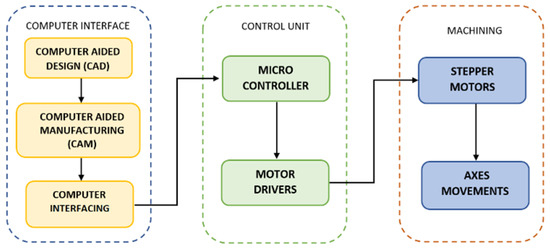
Figure 1.
Flowchart for the working of 5-axis CNC machine.
The objective of this paper is to propose a low-cost, custom-made design of five-axis CNC with X, Y, Z, A and C axes for educational purposes and manufacturing jobs. The paper discusses the mechanical assembly, electrical actuation and control system of proposed design, which have been verified by a SolidWorks motion study.
2. Mechanical Assembly
The end effector performs translational motion along X, Y and Z axes by changing the rotational movement of driving motor into linear movement. The motor shafts are connected to the ball screws with flexible couplers. The ball screws of C5 accuracy grade rotates and the ball screw nut moves linearly with linear movement guide, which increases smoothness. This linear actuation system is shown in Figure 2. The displacement length per one pulse output from NC is defined as a BLU (Basic Length Unit) [5]. C-axis table’s shaft is coupled with a worm wheel and worm gear mechanism, and the worm gear shaft is coupled with the driving motor with a flexible coupler, as shown in Figure 3a. The worm gear transmits the power to the worm wheel, which is set perpendicularly, with amplified torque. The A axis is directly connected with the A-axis-driving motor shaft, which tilts the rotary table in the clockwise and counter-clockwise directions. Table 1 shows the specifications of the mechanical assembly of our design.
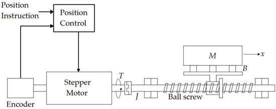
Figure 2.
Linear actuation control system.
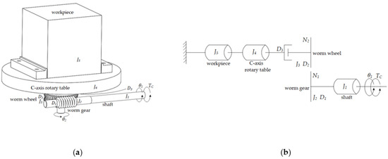
Figure 3.
C-axis: (a) Computer-aided model with impedances (inertia and viscous friction) for torque TC; (b) the free body diagram representing all the impedances that have to be reflected towards the N1 side.

Table 1.
Travelling dimensions of five axes and tolerances of ball screws [6].
3. Electrical Actuation and Control
Closed-loop stepper motors are being used for axis movements. Open-loop motors can be used in systems where the accuracy is very critical [5]. In closed-loop types, an encoder is attached to the shaft of the motor (Figure 2), which provides feedback of the rotation angle. Stepper motors are comparatively economical and provide high holding torque.
3.1. X, Y and Z Axes
The linear displacement x of mass M is given in Equation (1), and the force exerted on mass by ball screw FM is given in Equation (2):
where l is the screw lead (linear travel that the nut makes per one revolution of ball screw), and T′ is the resistance torque exerted by the mass on the ball screw. The transfer function of the control system in Figure 2 is given in Equation (3).
3.2. C-Axis
The rotary table carries the work piece (stock) in our design for rotation about the C and A axes, parallel to Z and X axes, respectively. Due to the inertia of the stock, significant torque is required; hence, the simulation of the torque required to rotate the C and A axes is performed.
The transfer function for the control system in Figure 3 is given in Equation (4).
3.3. A-Axis
Since A-axis’ rotation is based on direct drive as shown in Figure 4, all the impedances are added for torque TA for which its curve is obtained by a SolidWorks motion analysis (Figure 5b) by rotating the aluminum stock 90° clockwise and then 20° counter-clockwise.
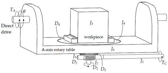
Figure 4.
A-axis computer-aided model with impedances for torque TA.
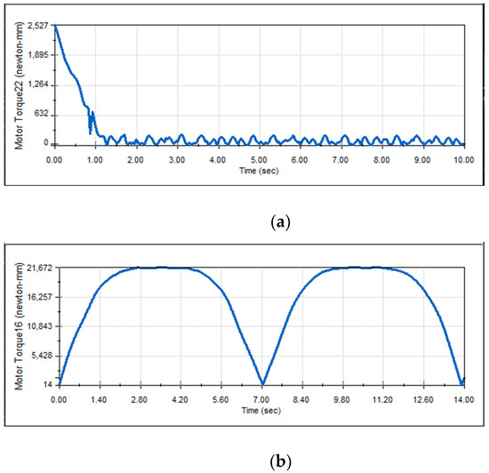
Figure 5.
Required torque curve for rotation of: (a) C-axis; (b) A-axis.
4. Results and Discussion
The following results were obtained by the motion analysis of the proposed design.
In order to achieve the correct selection of motor size, a few simulations have been performed. A and C are the axes that are carrying the work piece; therefore, their torque is simulated with the maximum weight of the work piece. The torque curve required to rotate the C-axis with a maximum stock size of (200 × 165 × 120) mm of 6061-T6 Aluminum alloy, which weighs 10.7 kg, at uniform speed of 120 rpm is obtained by a SolidWorks motion analysis, as shown in Figure 5a. The most used aluminum alloy is 6061-T6 for milling and most manufacturing companies recommend it as the standard grade for CNC machining [7]. It shows that the required torque to rotate the C-axis with the stock is 2.527 Nm, and as it starts rotating at a uniform velocity, the torque requirement decreases.
Similarly, A-axis simulation has been carried out on SolidWorks, as shown in Figure 5b. The motion study shows that, in order to rotate A-axis at 90° clockwise and 20° counter clockwise, 21.6 Nm torque is required; this is why an available motor of 22 Nm torque is selected.
With the help of obtained results, stepper motors were selected for the linear movements along the X, Y and Z axes and rotational movements about A and C axes which are mentioned in Table 2.
Table 2.
Stepper motors selection for axes movements [8].
5. Conclusions
The paper presented a pre-feasibility study for the development of a multi-axis CNC machine including the mechanical assembly and motor selection for the electric actuation of linear and rotary axes. Transfer functions for the relationship between linear and rotational displacement outputs and torque input for the dynamic systems have been calculated. The obtained results are used for the components’ selection.
6. Future Work
We will use the proposed design with the mentioned dimensions of mechanical assembly and electrical actuators for implementation on the hardware and interfaced with software. Preliminary tests for a particular benchmark job with different cutting tools, changing feed rates, optimal loads and roughing step-downs will be performed and accuracy tests for X, Y, Z, A and C axes movements will be conducted; ultimately, the machine will be used in HHRCM Lab (NCRA), NEDUET, for manufacturing and research purposes.
Author Contributions
Conceptualization, M.M.A.K. and H.Y.; methodology, H.I. and I.A.; software, H.I. and I.A.; validation, R.U. and H.K.; formal analysis, H.Y. and M.M.A.K.; resources, R.U.; writing—original draft preparation, H.I. and M.M.A.K.; writing—review and editing, R.U. and H.K.; visualization, H.I. and I.A.; supervision, R.U.; project administration, R.U. All authors have read and agreed to the published version of the manuscript.
Funding
This work was supported by the Higher Education Commission of Pakistan under a grant titled “Establishment of National Centre of Robotic and Automation (DF-1009-31)”.
Institutional Review Board Statement
Not applicable.
Informed Consent Statement
Not applicable.
Data Availability Statement
Not applicable.
Acknowledgments
The authors would like to acknowledge the technical support and assistance provided by Abdullah Haider Ali and Murtaza Kazmi of HHRCM Lab.
Conflicts of Interest
The authors declare no conflict of interest.
References
- My, C.A.; Bohez, E.L. A novel differential kinematics model to compare the kinematic performances of 5-axis CNC machines. Int. J. Mech. Sci. 2019, 163, 105–1117. [Google Scholar] [CrossRef]
- da Rocha, P.A.; e Souza, R.D.; de Lima Tostes, M.E. Prototype CNC Machine Design. In Proceedings of the 9th IEEE/IAS International Conference on Industry Applications—INDUSCON 2010, São Paulo, Brazil, 8–10 November 2010. [Google Scholar]
- Bohez, E.L.J. Five-axis milling machine tool kinematic chain design and analysis. IJMTM 2002, 42, 505–520. [Google Scholar] [CrossRef]
- LinuxCNC. Available online: http://linuxcnc.org/docs/html/motion/5-axis-kinematics.html (accessed on 9 February 2022).
- Suh, S.H.; Kang, S.K.; Chung, D.H.; Stroud, I. Theory and Design of CNC Systems; Springer Science & Business Media: Berlin/Heidelberg, Germany, 2008; pp. 8–19. [Google Scholar]
- Design World. Available online: https://www.designworldonline.com/what-to-look-for-when-choosing-a-precision-ball-screw/ (accessed on 10 February 2022).
- Fast Radius. Available online: http://www.fastradius.com/resources/cnc-materials-aluminum-alloys/ (accessed on 8 February 2022).
- STEPPERONLINE. Available online: https://www.omc-stepperonline.com/ (accessed on 8 February 2022).
Publisher’s Note: MDPI stays neutral with regard to jurisdictional claims in published maps and institutional affiliations. |
© 2022 by the authors. Licensee MDPI, Basel, Switzerland. This article is an open access article distributed under the terms and conditions of the Creative Commons Attribution (CC BY) license (https://creativecommons.org/licenses/by/4.0/).