
Analysis of ADAS Radars with Electronic Warfare Perspective

Abstract
:1. Introduction
2. Intentional Jamming of ADAS Sensors
2.1. Security of ADAS Sensors
2.2. Electronic Warfare
2.3. DRFM
2.4. Jamming ADAS Radar Systems
- Step-1: Define the assumptions and LRR parameters used on the analysis.
- Step-2: Calculate the necessary jamming power for the desired Jamming-to-Signal Ratio (JSR) on the radar detection.
- Step-3: Define jamming scenarios.
- Step-4: Investigate the jamming scenarios to find the necessary jamming power.
- Step-5: Investigate the effects of jamming on radar detection at radar Range Doppler Map (RDM) and 2-Dimensional Constant False Alarm Rate (2D-CFAR).
- Step-6: Analyze the possible jamming system.
2.4.1. Step-1: Define the Assumptions and LRR Parameters Used on the Analysis
- The LRR uses linear polarization as referred in Table 1. In case the orientation of the linear polarization is not known, the jammer must use circular polarization to improve the jamming chance with the loss of 3 dB.
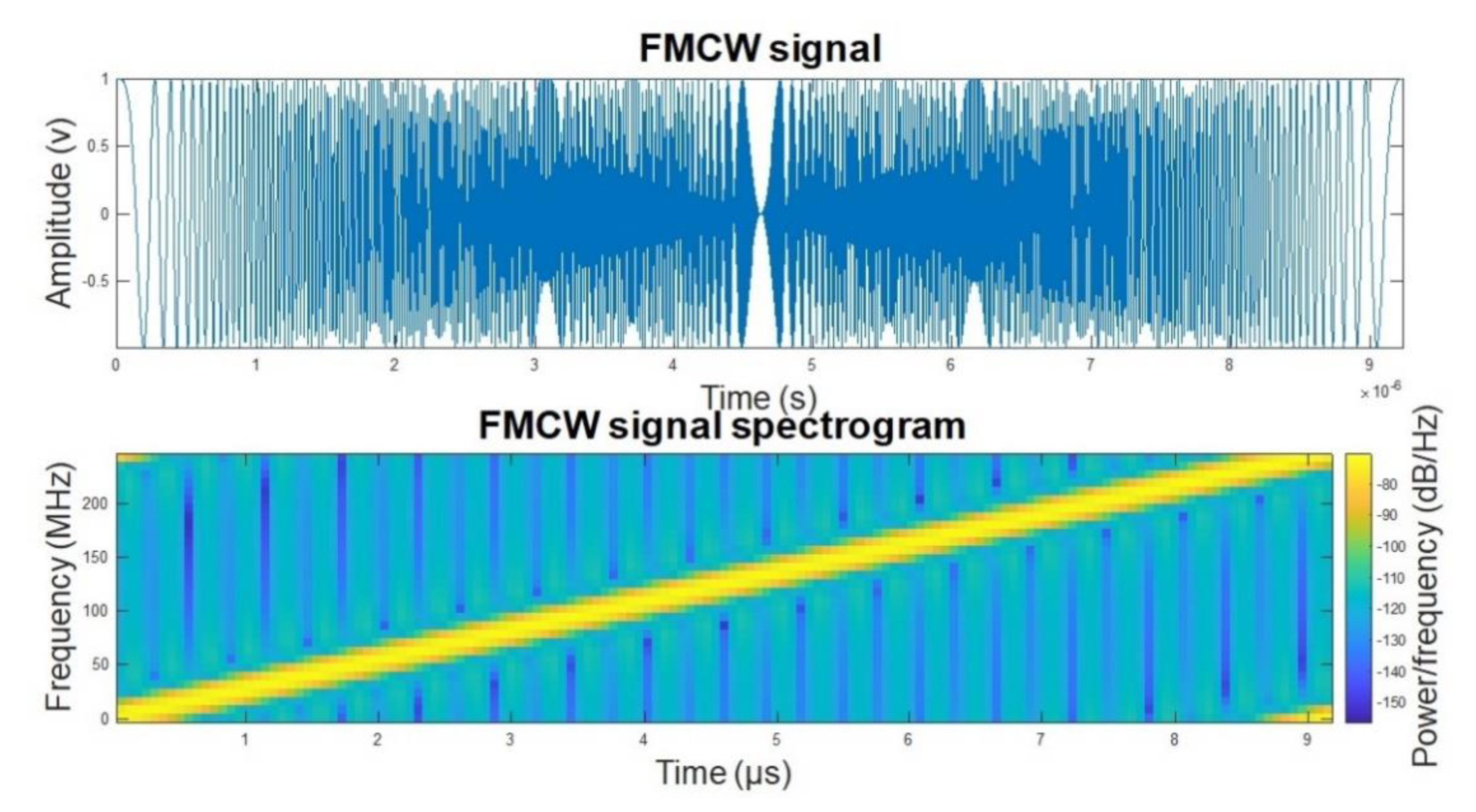
- FMCW radars have high processing and modulation gains, so it is difficult to jam them with noncoherent jamming methods. The best jamming method is to use a DRFM to achieve a coherent jamming.
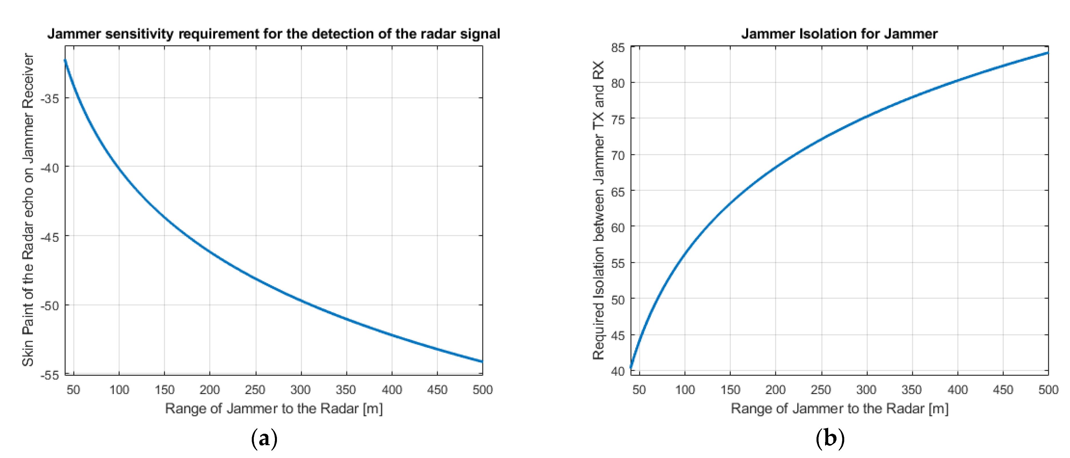
- For effective jamming, the jammer has to monitor radar parameters. In case there is a parameter update on the radar, then the jammer has to update the jamming parameters. Hence, the jammer needs a receiving cycle (look-through) and during that time the jamming could be interrupted which reduces the effects of the jamming. In this study, it is assumed that the jammer can receive and transmit simultaneously without any interruptions so that the jammer can follow radar parameters. For that purpose, the required isolation between jammer receiver and transmitter is calculated and presented below.
- The jamming power, detected by the victim radar antenna, is analyzed for four different scenarios initially. It is assumed that the jamming signals, which are generated by a DRFM and the jammer signals are up to date, are processed by the radar like real object echo signals. For one scenario, radar detection and processing with RDM and 2D-CFAR are investigated to inspect the expected outcome on the radar detection process.
- The DRFM memory size is not considered a problem for the jamming, especially for long pulses.
- The propagation delay of the jammer is not considered. There is a propagation delay in the jamming system. So, the jamming signal arrives later than the real echo signal. If the jammer can follow the radar parameter, with the appropriate timing, this delay can be compensated by the jammer.
- Because of the spatial diversity of a MIMO radar, it is difficult to jam them [23]. For RVGPO/I techniques, the jammer is assumed to be in the same angle with the manipulated real target.
- Compared to the radar signal, which matches with the radar receiver setting, the jammer signal has a certain amount of jamming losses. Jamming losses for a stationary jammer is 12 dB and for a mobile jammer, 9 dB are considered because of the following reasons:
- (a)
- It is assumed that the stationary jammer stays on the roadside, and they are on the edge of the −3 dB beamwidth. For a mobile jammer case, no loss is considered as they might be on the boresight of the jammer antenna.
- (b)
- MIMO radars can generate simultaneously multiple transmit (Tx) beams [24]. Maximum coherency is achieved when all Tx channels transmit simultaneously using the same bandwidth [9]. However, we assumed that all channels transmit in different bandwidths to consider the worst case for the required jamming power. To jam all these signals simultaneously, jamming power split to four which results in 6 dB loss in the jammer output.
- (c)
- The polarization loss is taken as 3 dB.
2.4.2. Step-2: Calculate the Necessary Jamming Power for the Desired JSR on the Radar Detection
2.4.3. Step-3: Define Jamming Scenarios
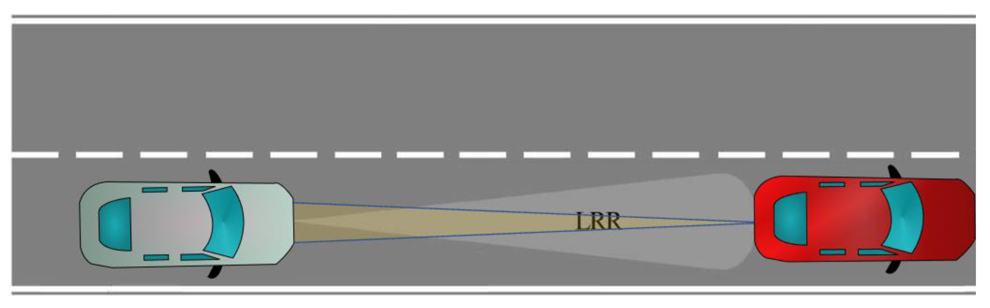
Scenario-1
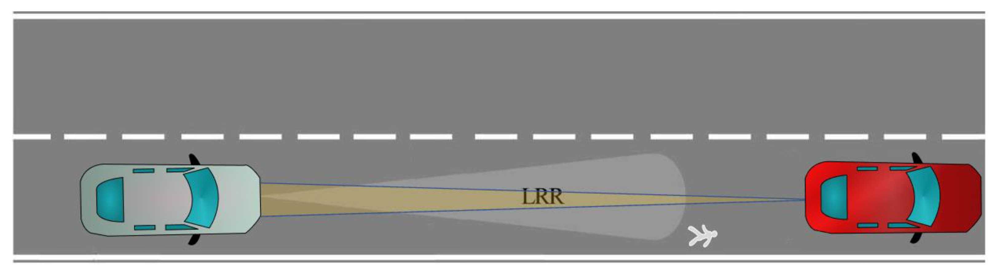
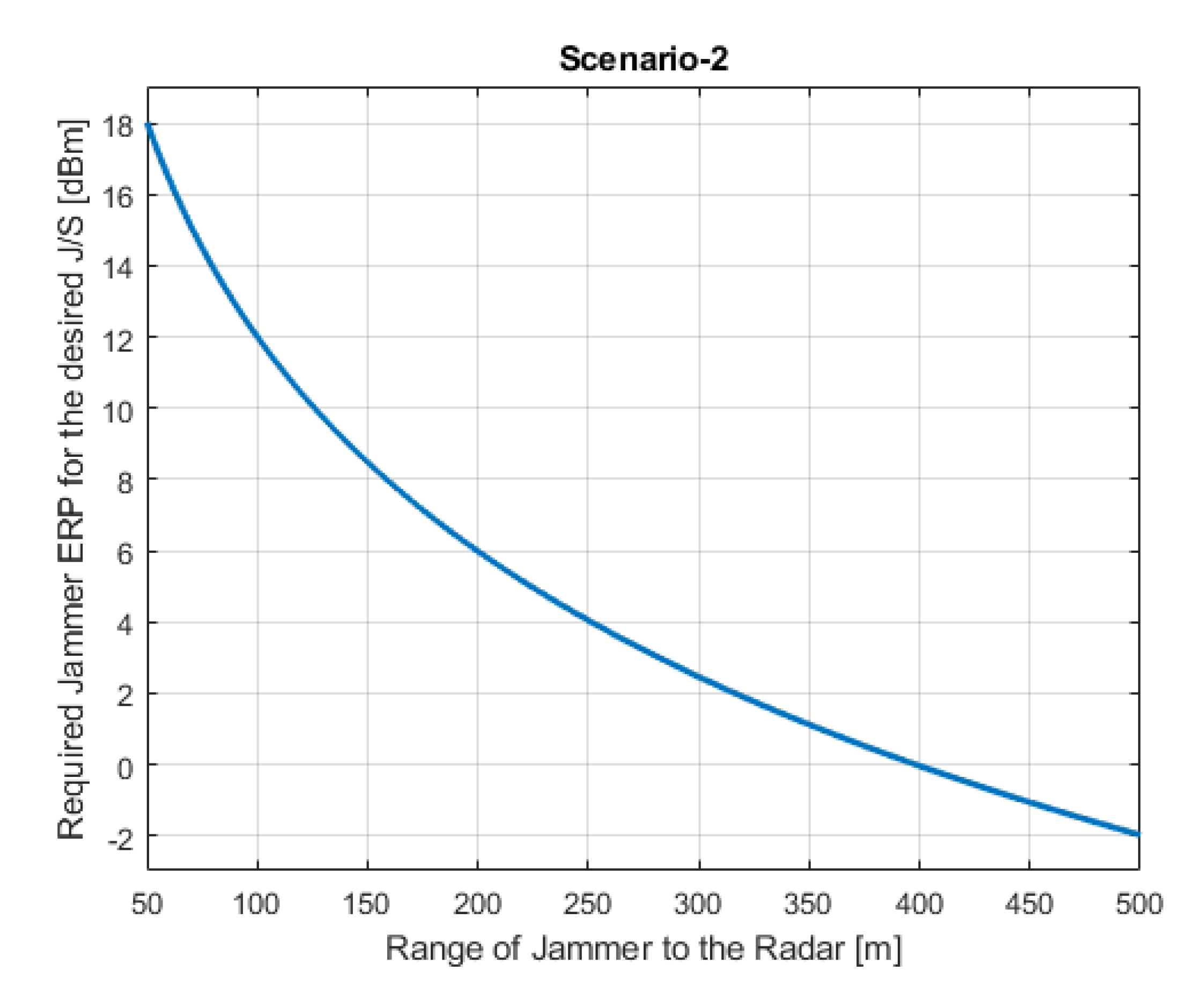
Scenario-2
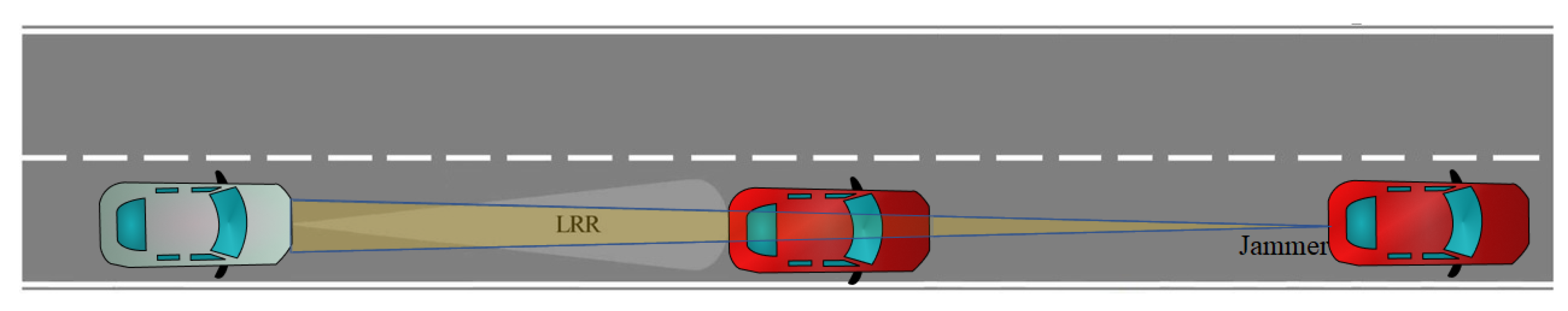
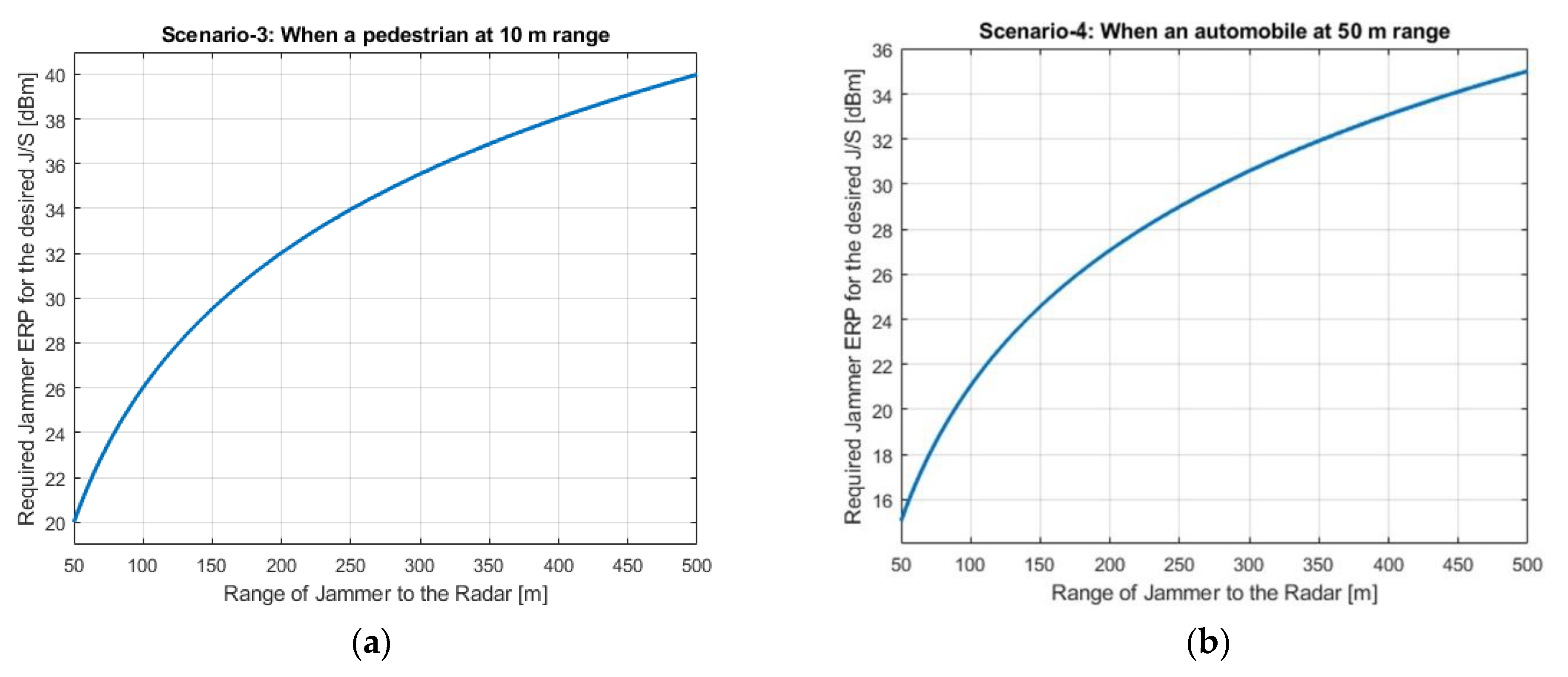
Scenario-3
Scenario-4
2.4.4. Step-4: Investigate the Jamming Scenarios to Find the Necessary Jamming Power
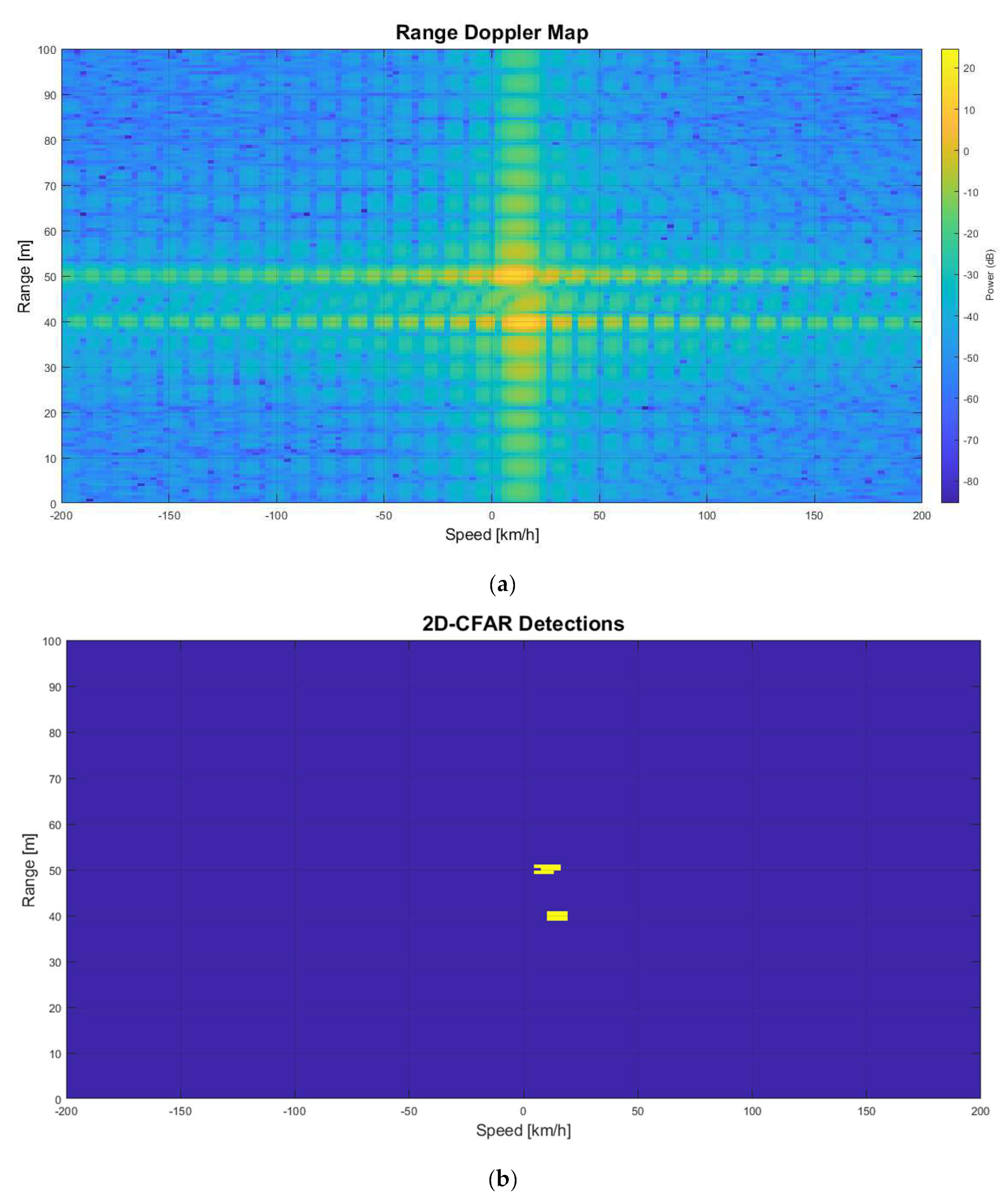
2.4.5. Step-5: Investigate the Effects of Jamming on Radar Detection at Radar RDM and 2D-CFAR
- Two-dimensional CFAR detector
- Probability of False Alarm Rate (FAR) is %0.000000001 (1 × 10⁻⁹)
- Guard band size is 3 cells
- Training band size is 10 cells
2.4.6. Step-6: Analyze the Possible Jamming System
3. Results
Author Contributions
Funding
Institutional Review Board Statement
Informed Consent Statement
Conflicts of Interest
References
- Adamy, D.L. EW 101: A First Course in Electronic Warfare, 1st ed.; Artech House Publishers: London, UK, 2001; Volume 101. [Google Scholar]
- Kukkala, V.K.; Tunnell, J.; Pasricha, S.; Bradley, T. Advanced Driver-Assistance Systems: A Path Toward Autonomous Vehicles. IEEE Consum. Electron. Mag. 2018, 7, 18–25. [Google Scholar] [CrossRef]
- Bilik, I.; Longman, O.; Villeval, S.; Tabrikian, J. The Rise of Radar for Autonomous Vehicles: Signal Processing Solutions and Future Research Directions. IEEE Signal Process. Mag. 2019, 36, 20–31. [Google Scholar] [CrossRef]
- Zhou, T.; Yang, M.; Jiang, K.; Wong, H.; Yang, D. MMW Radar-Based Technologies in Autonomous Driving: A Review. Sensors 2020, 20, 7283. [Google Scholar] [CrossRef]
- Patole, S.M.; Torlak, M.; Wang, D.; Ali, M. Automotive radars: A review of signal processing techniques. IEEE Signal Process. Mag. 2017, 34, 22–35. [Google Scholar] [CrossRef]
- Jones, W. Keeping cars from crashing. IEEE Spectr. 2001, 38, 40–45. [Google Scholar] [CrossRef]
- Kobashi, S.; Kurono, Y.; Shono, M.; Shirakawa, K.; Isaji, O.; Fujimoto, M.; Okubo, N. 3D-Scan Radar for automotive application. In Proceedings of the 19th ITS World Congress, Vienna, Austria, 22–26 October 2012; pp. 3–7. [Google Scholar]
- Gresham, I.; Jain, N.; Budka, T.; Alexanian, A.; Kinayman, N.; Ziegner, B.; Brown, S.; Staecker, P. A compact manufacturable 76-77-GHz radar module for commercial ACC applications. IEEE Trans. Microw. Theory Tech. 2001, 49, 44–58. [Google Scholar] [CrossRef]
- Hakobyan, G.; Yang, B. High-performance automotive radar: A review of signal processing algorithms and modulation schemes. IEEE Signal Process. Mag. 2019, 36, 32–44. [Google Scholar] [CrossRef]
- Yan, C.; Xu, W.; Liu, J. Can you trust autonomous vehicles: Contactless attacks against sensors of self-driving vehicle. Comput. Sci. 2016, 24, 109. [Google Scholar] [CrossRef]
- Lazaro, A.; Porcel, A.; Lazaro, M.; Villarino, R.; Girbau, D. Spoofing Attacks on FMCW Radars with Low-Cost Backscatter Tags. Sensors 2022, 22, 2145. [Google Scholar] [CrossRef] [PubMed]
- Komissarov, R.; Wool, A. Spoofing attacks against vehicular FMCW radar. arXiv 2021, arXiv:2104.13318. [Google Scholar]
- Kapoor, P.; Vora, A.; Kang, K.-D. Detecting and Mitigating Spoofing Attack Against an Automotive Radar. In Proceedings of the 2018 IEEE 88th Vehicular Technology Conference (VTC-Fall), Chicago, IL, USA, 27–30 August 2018; pp. 1–6. [Google Scholar] [CrossRef]
- Furqan, H.M.; Solaija, M.S.J.; Türkmen, H.; Arslan, H. Wireless communication, sensing, and REM: A security perspective. IEEE Open J. Commun. Soc. 2021, 2, 287–321. [Google Scholar] [CrossRef]
- Yeh, E.R.; Choi, J.; Prelcic, N.G.; Bhat, C.R.; Heath, R.W., Jr. Security in Automotive Radar and Vehicular Networks. Microw. J. 2016, 60, 148–164. [Google Scholar]
- Kunert, M. The EU project MOSARIM: A general overview of project objectives and conducted work. In Proceedings of the 2012 9th European Radar Conference, Amsterdam, The Netherlands, 31 October–2 November 2012. [Google Scholar]
- Deparment of the Army. Electronic Warfare; Joint Chiefs of Staff (CJCS)-Armed Forces of the United States of America: Washington, DC, USA, 2012.
- De Martino, A. Introduction to Modern EW Systems; Artech House Publishers: London, UK, 2012. [Google Scholar]
- Neng-Jing, L.; Yi-Ting, Z. A survey of radar ECM and ECCM. IEEE Trans. Aerosp. Electron. Syst. 1995, 31, 1110–1120. [Google Scholar] [CrossRef]
- Roome, S. Digital radio frequency memory. Electron. Commun. Eng. J. 1990, 2, 147–153. [Google Scholar] [CrossRef]
- ECC Report, 262. Studies Related to Surveillance Radar Equipment Operating in the 76 to 77 GHz Range for Fixed Transport Infrastructure. (Approved 27 January 2017). Available online: http://spectrum.welter.fr/html/spectrum-cept-ecc-reports.html (accessed on 23 June 2022).
- Kamel, E.B.; Peden, A.; Pajusco, P. RCS modeling and measurements for automotive radar applications in the W band. In Proceedings of the 2017 11th European Conference on Antennas and Propagation (EUCAP), Paris, France, 19–24 March 2017. [Google Scholar] [CrossRef]
- Song, X.; Willett, P.; Zhou, S. Jammer detection and estimation with MIMO radar. In Proceedings of the 2012 Conference Record of the Forty Sixth Asilomar Conference on Signals, Systems and Computers (ASILOMAR), Pacific Grove, CA, USA, 4–7 November 2012; pp. 1312–1316. [Google Scholar] [CrossRef]
- Pfeffer, C.; Feger, R.; Wagner, C.; Stelzer, A. FMCW MIMO Radar System for Frequency-Division Multiple TX-Beamforming. IEEE Trans. Microw. Theory Tech. 2013, 61, 4262–4274. [Google Scholar] [CrossRef]
- Davidson, K.; Bray, J. Understanding Digital Radio Frequency Memory Performance in Countermeasure Design. Appl. Sci. 2020, 10, 4123. [Google Scholar] [CrossRef]


| LRR Parameters | Values |
|---|---|
| LRR max range | 250 m |
| Tx/Rx antenna max gain (single element) | 20–25 dBi |
| Tx/Rx antenna beamwidth (−3 dB) Azimuth | ± 5° |
| Tx power ERP (peak) | 30–40 dBm (40 dBm is used here) |
| Rx typical Noise Figure | 15 dB |
| Rx IF typical noise floor | −99 dBm/MHz |
| Rx IF bandwidth (After signal processing) | 500 kHz–25 MHz |
| Antenna polarization | Horizontal, Vertical, Diagonal |
| Interference, clutter removal technique | CFAR |
| Object | RCS Values |
|---|---|
| Automobile | 19–25 dBm2 (20 dBm2 used here) |
| Pedestrian | −3 dBm2 |
| Parameters | Values |
|---|---|
| Relative distance of the real object | 50 m |
| Relative distance of the false echo generated by jamming | 45 m |
| The speed of radar platform | 100 km/h |
| The speed of real object | 90 km/h |
| The speed of false echo | 85 km/h |
| Desired JSR | 10 dB |
| Scenario | Expected Result | Effect Level |
|---|---|---|
| 1. Generate false pedestrian/automobile echo by CFT | False echo is detected by the LRR, and the ADAS is expected to act. Depending on the false echo parameters, emergency brake might be applied. | Driving quality reduced. Depending on the circumstances, an accident might happen. |
| 2. Deception jamming with RVGPO/I | The real object information could not be detected. Depending on the jamming direction: RVGPO: The LRR measures farther distance than the real value. RVGPI: The LRR measures shorter distance than the real value. | Driving quality reduced. RVGPO: The LRR perceives longer free space in front of the automobile, in case the detection threshold increased, and the real object cannot be detected anymore. In this scenario jammer platform can also be affected so it would be considered as not a realistic scenario. RVGPI: The LRR perceives shorter free space in front of the automobile, and act to decrease the speed of the platform. Depending on the circumstances, an accident may happen. |
| 3–4. Deception Jamming. Manipulate the measured radar parameters for the pedestrian/automobile which is already detected by the radar. | Jamming signal with higher JSR, increases the detection threshold and hide the real echo. If the techniques are effective, then the radar will detect only the jammer signal. Depending on the jamming signal, the LRR provides wrong information about the pedestrian/automobile. RVGPO: The LRR measures the pedestrian/automobile farther and did not react in time. RVGPI: The LRR measures shorter distance than the pedestrian/automobile and apply emergency brake. | RVGPO: The LRR perceives longer free space in front of the automobile, in case the detection threshold increased, and the real object cannot be detected anymore. In this scenario jammer platform can also be affected so it would be considered as not a realistic scenario. |
Publisher’s Note: MDPI stays neutral with regard to jurisdictional claims in published maps and institutional affiliations. |
© 2022 by the authors. Licensee MDPI, Basel, Switzerland. This article is an open access article distributed under the terms and conditions of the Creative Commons Attribution (CC BY) license (https://creativecommons.org/licenses/by/4.0/).
Share and Cite
Cemil, A.; Ünlü, M. Analysis of ADAS Radars with Electronic Warfare Perspective. Sensors 2022, 22, 6142. https://doi.org/10.3390/s22166142
Cemil A, Ünlü M. Analysis of ADAS Radars with Electronic Warfare Perspective. Sensors. 2022; 22(16):6142. https://doi.org/10.3390/s22166142
Chicago/Turabian StyleCemil, Alper, and Mehmet Ünlü. 2022. "Analysis of ADAS Radars with Electronic Warfare Perspective" Sensors 22, no. 16: 6142. https://doi.org/10.3390/s22166142
APA StyleCemil, A., & Ünlü, M. (2022). Analysis of ADAS Radars with Electronic Warfare Perspective. Sensors, 22(16), 6142. https://doi.org/10.3390/s22166142