1. Introduction
The use of a single quartz crystal for sensing is a well-known and important measuring technique based on the stability and reliability of the crystal oscillation [
1,
2,
3,
4]. Next to the mechanical influence on the crystal oscillation, one can also affect the reactance of the crystal and thus its serial resonant frequency [
5,
6,
7,
8,
9]. Because the change in frequency is measurable already for extremely low changes in the reactance (for capacitance changes in the region of aF and zF), the method is useful for several applications, such as mechanical displacement, nanopositioning, eccentric motion, strain sensing, dielectric properties of liquids, density of liquids, small volumes, low pressure, etc. [
10,
11,
12,
13,
14,
15,
16,
17,
18]. In addition, when the reactance-to-frequency conversion is used, quartz crystals are applicable as biosensors, in medicine and at specific chemical measurements [
14,
19,
20,
21,
22,
23,
24]. The reactance is first transformed into a frequency signal and then into a measured physical or chemical quantity. The reactance-to-frequency conversion is important in measurements where tiny changes in the capacitance (in the region of aF and zF) have to be measured with a high accuracy [
3,
10,
19,
23].
The basic purpose of the research presented in this paper was to improve the sensitivity of the high-resolution reactance-to-frequency transducer used in previous research [
5,
25] by connecting several quartz crystals in parallel in the oscillator. The research is oriented towards a comparison of oscillators with one, two, or three quartz crystals connected in parallel, when the load capacitor (capacitive reactance) with capacitance of the order fF is connected in parallel with the quartz crystals. Because quartz crystals have their own frequency–temperature characteristic that depends on the cut angle, we use the switching mode operation of the oscillator for temperature compensation.
Compared to other methods [
26,
27,
28,
29], the major advantageous characteristics of the proposed method are as follows: a conversion of reactance into frequency (measuring range in the fF region with sensitivity in the zF region); compensation of the quartz eigen temperature characteristics; and a simultaneous temperature compensation by the reference frequency oscillator [
30]. By the proposed method, we also compensate for the ageing of the crystals [
31], the effect of the reference capacity and parasitic impedances in the circuit [
22,
32], and the effects of nonideal properties of the electronic components, which affect the oscillation frequency. Important also is the compensation of small changes in the supply voltage of the oscillator, which, unless compensated, affects the stability of the oscillator frequency [
27,
33,
34,
35,
36]. An important advantage of the switching method is also a high temperature dynamic stability and an extended temperature region of operation (
). The switching mode operation of the oscillator enables a high stability of oscillation at a very low sensing capacity and reduces the start-up time from
min to
min [
33,
37,
38]. The method is simple with a low number of elements that are required in the circuit. In addition, crystals with different cut angles can be used for different applications.
The paper is structured as follows. First, we present an equivalent circuit of a quartz crystal and study the impedance circles if shunt capacitors are connected in parallel to one, two, or three quartz crystals, also connected in parallel. Then we study the resonant conditions for different combinations of crystals and shunt capacitances. Next, we present the experimental setup, the results of the measurements, and finally discuss the obtained results.
2. Impedance of One, Two, and Three Quartz Crystals in Parallel
The series resonance frequency
of a single AT-quartz crystal is
where
and
are motional inductance and capacitance, respectively. A quartz crystal is represented by an equivalent circuit in which a coil with inductance
, capacitor with inductance
, and resistor with a motional resistance
are connected in series, while a shunt capacitor with capacitance
is connected in parallel [
7,
8,
9,
34,
37].
A complex impedance (
) of one quartz crystal is given as
where
is the angular frequency and
is the imaginary unit. The shunt capacitance
in Equation (2) presents the capacitance between the electrodes and a stray capacitance associated with the mounting structure.
To study the impedance close to the resonant frequency, we define the frequency ratio (
)
where
is the resonant angular frequency. Equation (2) can now be transformed into [
7]:
For two crystals in parallel, the complex impedance (
) is
where indices
and 2 denote the first and the second quartz crystal, respectively. In the case of two identical crystals, Equation (5) reduces to
, where
is given by Equation (4).
Three crystals in parallel can be considered as one crystal in parallel with a crystal dublet, and from Equation (5) we deduce the expression for the complex impedance (
) of a triplet:
where index
denotes the third quartz crystal. In the case of three identical crystals, Equation (6) reduces to
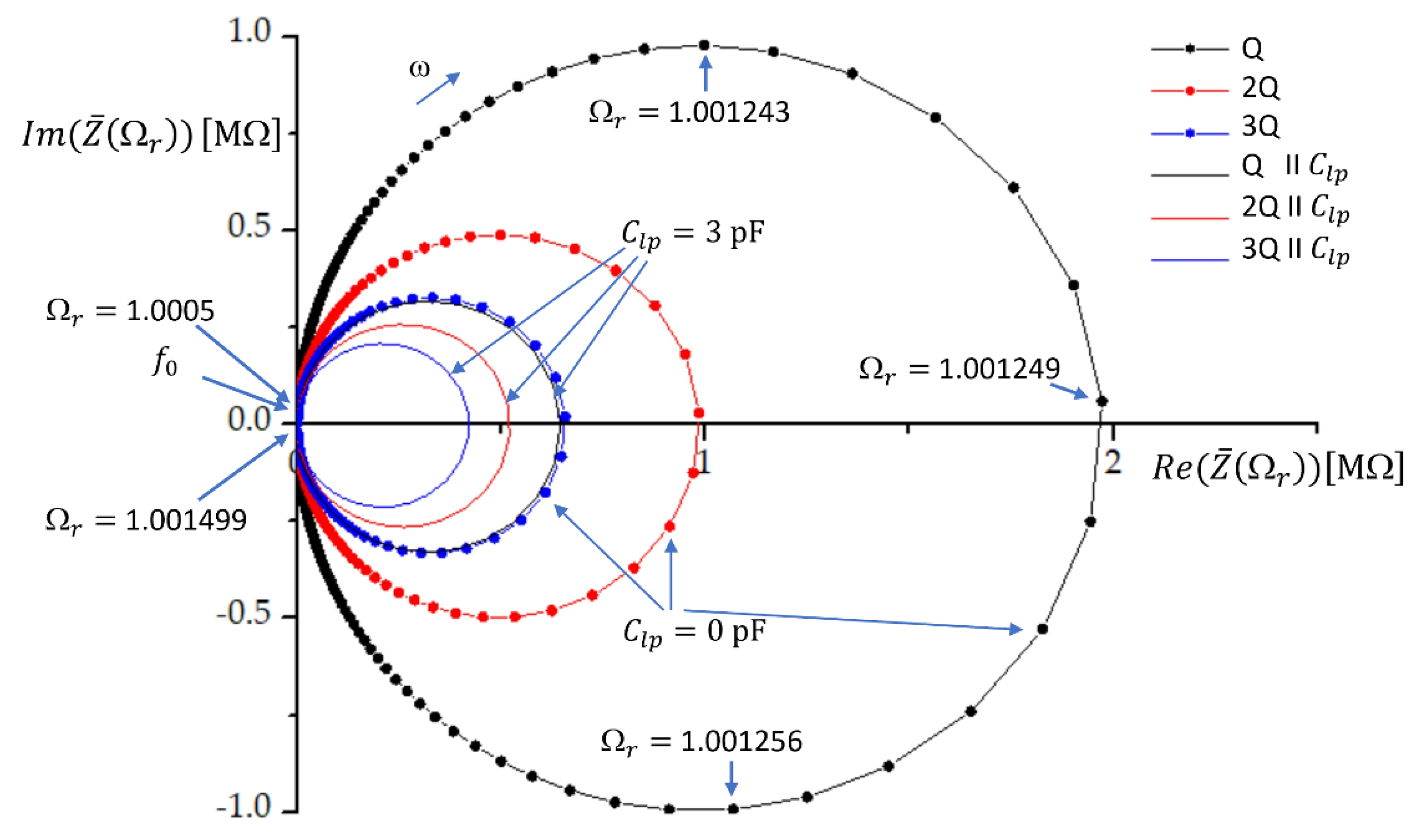
. The impedance characteristics for one, two, and three quartz crystals in parallel are given in
Figure 1. The ratio
varied from 1.0005 to 1.001499 with a step of
. The quartz crystal parameters chosen for plotting were
,
,
, and
Ω. At these parameters, the resonant frequency is
. At the resonant frequency
, the real and imaginary parts of the impedance are very low. When the (angular) frequency increases, the impedance curve crosses the real axis; thus, the imaginary part of the impedance is zero at a very high real part of impedance. This frequency is called the antiresonance or parallel resonance frequency of the crystal and depends on the value of the shunt capacitance.
at the parallel resonance frequency is given by
[
7].
In this research, the load capacitor with capacitance
is connected in parallel with one, two, or three quartz crystals. The load capacitance reduces the impedance, as shown in
Figure 1. By using Equation (3), the impedance of the load capacitor can be expressed as
The impedance of one quartz crystal in parallel with the load capacitor (
) can now be expressed as
where
is given by Equation (4). For two identical crystals in parallel and parallel to
, the impedance
is given as
while for three crystals in parallel with
we have
While having two or three crystals in parallel has no effect on the resonant frequency (only the impedance is reduced), we see that the addition of the load capacitance will affect the antiresonant frequency as well, while the resonant frequency remains
. The resonant and antiresonant frequencies are found by setting the imaginary part of the impedance (Equation (4)) to zero. By neglecting the effect of
(
= 0) it is straightforward to find new antiresonant frequencies for one, two, or three crystals connected in parallel. Because of the parallel load capacitance, the antiresonant frequency of the crystal is pulled to frequency
[
7,
33]:
When two crystals are connected in parallel, the new resonant frequency (
) is
where we have a new shunt capacitance, which is the sum of the shunt capacitances of both quartz crystals [
32]. We have assumed that the quartz crystals are identical; thus, the shunt capacitance is
.
When three crystals are connected in series, the shunt capacitances of all three of them affect the resonant frequency
, which is thus given by
where
is the shunt capacitance of the three equal quartz crystals.
We define the frequency pulling range (
) for one crystal between two load capacitance values
and
as
Thus, when three crystals are connected in parallel, the frequency pulling range (
) is
From
Figure 1 we see that the impedance circle is reduced most when we have only one crystal in parallel with the load capacitance. The relative reduction of the impedance circle is much lower when we have two or three crystals in parallel. This means that the impedance conditions will be less affected by the load capacitance if we have multiple crystals in parallel. The multiple feedback loops in oscillators ease the oscillation of the crystals, which results in the increase in the pulling range [
6].
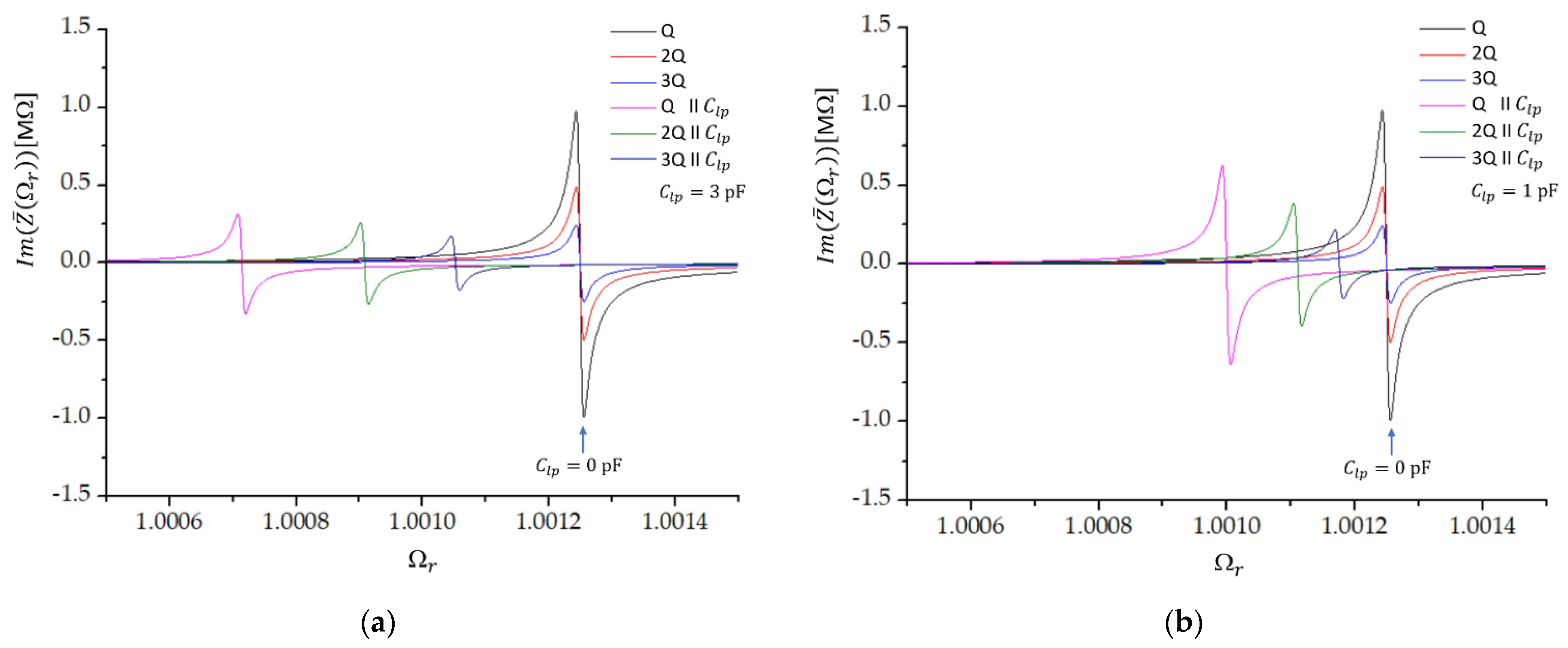
Figure 2 shows the imaginary part of the impedance as a function of the frequency ratio
when the load capacitor with capacitance
is connected in parallel to one (Q), two (2Q), or three (3Q) crystals in parallel. Without the load capacitance, all three crystals have the same antiresonant frequency
; only the amplitude is changed. When the load capacitor is added, the change in the resonant frequency as well as the reduction in the magnitude of the imaginary part of impedance are the largest in the case of one crystal and the lowest in the case of three crystals in parallel. We also see that the shift in the resonant frequency increases when the load capacitance is increased, while the magnitude of the imaginary part of impedance reduces with increasing value of
(
Figure 2b).
3. Experimental Setup
Several oscillator electronic circuits have been investigated so far [
1,
33,
38,
39,
40,
41,
42]. Their common feature is a problem with the stability of the crystal oscillation, the temperature effect on crystal oscillation, ageing of the crystal as well as other elements in the circuit, and the effect of parasitic impedances. We constructed an experimental circuit that reduces all the above-mentioned effects.
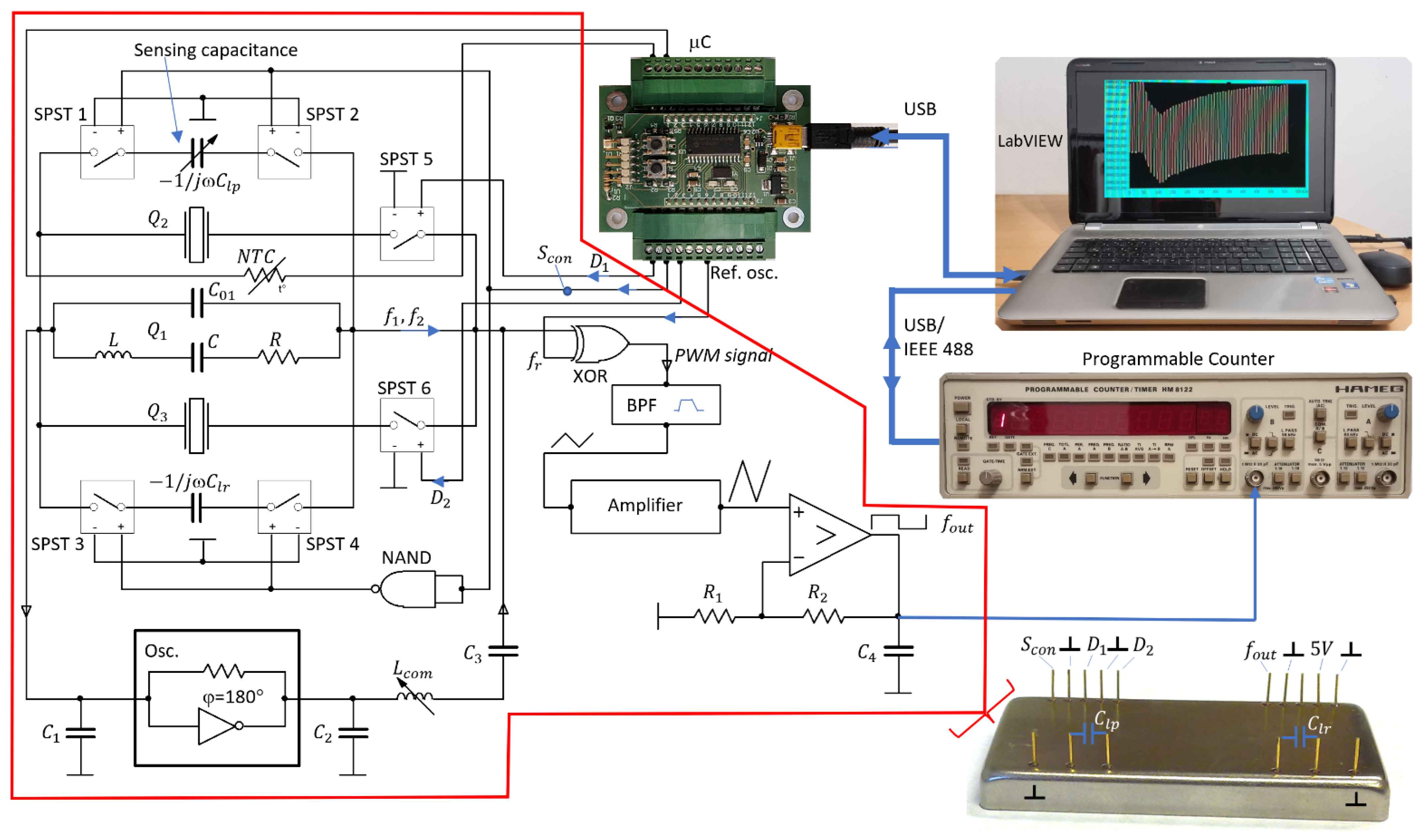
The experimental setup is shown in
Figure 3. Two additional quartz crystals,
and
, and an element to switch these crystals, are added to the quartz crystal oscillator. The second and third quartz crystal are connected to the first crystal by signals
and
through SPST (Single Pole Single Throw) switches; in this way, the parasitic capacitances are always the same.
This circuit enables an accurate analysis of the operation conditions of various connection of quartz crystals. The low-value reactance transducer consists of a modified oscillator circuit with one, two, and three quartz crystals, sensing reactance, and a switching part. The novelty in this approach is the use of a specific symmetrical switching mode quartz oscillator, in which multiple quartz crystals are connected in parallel, and in parallel to them, we connect two capacitors with low value reactances
and
, the first one being adjustable. The reactances are connected alternately with the help of the SPST 1–4 switches and enable a significant reduction in the influence of parasitic impedances on frequency change because of the symmetry of the circuit and because at any of the reactances the same combination of crystals is used. The capacitance
is a load capacitance, which enables a highly sensitive capacitance–frequency conversion at a simultaneous compensation of quartz crystals.
is a reference capacitance by which we achieve impedance conditions for a parallel connection of crystals and conditions for oscillator operation to be the same as in the case when
is connected. The switching of an oscillator, which is switching between frequencies
and
, is realized with the help of a control digital signal
(values 1 and 0) and a NAND gate, which produces an output, which is false only if both its inputs are true (
Figure 3) [
43]. A variable inductivity,
, is used to fine-tune both frequencies
and
for reactances
and
at a certain frequency
, and to set the sensitivity of the sensor [
28,
44,
45,
46,
47]. A pulse-wide modulated signal corresponding to the frequency difference between the frequency
and reference frequency
(from reference oscilator) or the difference between the frequency
and reference frequency enters the BPF (Band Pass Filter) [
48,
49,
50]. If the frequencies
and
(in our case) equal approximately 4 MHz and are a few kHz different from the frequency
, then these two frequencies are converted (depending on the signal
) to the range between
at the output of BPF. The upper frequency of BPF is
and the lower one
. A triangular signal obtained at the output of the BPF filter, which depends on
and
and the initially set frequency of
, is amplified by an amplifier to ease the transformation into a rectangular signal. The obtained rectangular signal is not yet temperature compensated. The temperature compensation is attained when the two sequential output frequencies are subtracted. Temperature compensations are also effects of the stray capacitance, which affect both frequencies
and
. The output signal frequency
contains both frequencies synchronically, depending on the switching frequency
(one measurement cycle is
). Capacitances
in
serve to suppress the spurious responses of the quartz crystals to avoid crystal oscillation at higher frequencies [
8,
9,
33].
A prototype of the multiple quartz sensor in the SMD technology on an
PCB basis is shown in
Figure 3. At the front side of the housing, the converter has pins for
and
. For specific industrial applications, the refence capacitor can also be incorporated inside the housing. At the back side of the housing, there are pins for a supply voltage,
,
and
signals, and an output frequency,
. The main advantage of such a construction is that it allows for a connection of the capacitance-sensitive elements to these pins with very low additional parasitic capacitances, and even these are—when the switching method is used—reduced to a minimum.
The circuit with a switching mode operation, shown in
Figure 3, achieves the temperature compensation of a single quartz crystal unit in the following way. When both reactances,
and
, are almost the same, then the two frequencies
and
are also almost the same at the signal states
and
, respectively, and depend on the quartz crystal resonant frequency,
, and changes of this frequency due to the quartz crystals’ temperature characteristics (
); the variation in
(
); the inequality of
and
; and on the quartz crystals’ ageing
. On the other hand, when reactances
and
differ by approximately 0.1%, the frequencies
and
already differ by the order of kHz. The output frequency (
) is the difference between the frequency
and the reference frequency
(
); similarly,
. If we calculate the difference between the two output frequencies,
,
,
, and
are well compensated if the temperature variations are slower than
because only one temperature quartz characteristic is involved. In a similar way, temperature variations in the reference frequency
are compensated. The output frequencies
and
, corresponding to the two logical states
and
, are measured by a programmable counter and LabVIEW and can be expressed as
and
where
and
are shifts in the resonant frequency due to the measured and reference capacitance, respectively, and
and
are the measurement errors of the programmable counter at measuring times
and
, respectively.
and
are temperatures at times
and
, respectively. If the signal switching is of the order of ms, one can assume that
and
; thus, the frequency shifts due to aging are the same and so are the frequency shifts
due to the temperature. The temperature-compensated final output frequency (
) is
What is left, is the temperature variation due to the changes in the measured reactance, , and the initial setting of the reference reactance and the counter measuring error at two sequential measurements of frequencies and , at times and , respectively.
In
Figure 3, the quartz crystal
is presented by an equivalent electric circuit. Its stray capacitance,
, includes the pin-to-pin input and output capacitances (parasitic capacitances). The typical value of the stray capacitance,
, is between 2.5 pF and 7 pF. By an additional influence on this stray capacitance (and by this on the equivalent circuit) through the parallel load capacitance, one can affect the frequency of the stable quartz crystal oscillator such that the oscillator acts as a capacitive-frequency transducer whose resolution is in the sub aF range.
With the compensation of
by a series inductivity
, as described in [
5,
8,
9,
25], one can obtain an almost linear dependence of frequency
on
close to the quartz resonant frequency. When three crystals are connected in parallel,
is used to compensate the sum of all three shunt capacitances
), and the frequencies
and
for both signal states
are
and
where
is a compensation factor, which depends on the compensation inductance and capacitances
,
, and
[
51].
Frequencies and (Equations (19) and (20)) depend on the switching state ( or ), chosen sensitivity , magnitude of the compensated shunt capacitance (), and on the magnitude of the measured () and reference () capacitance. Both frequencies depend also on the temperature change during the two switches and on the aging of the crystals. When the switching rate of the signal is high (of the order of ms), in two sequential switches of the signal and two sequential measurements of the corresponding frequencies and , followed by a subtraction of these two frequencies, the temperature variation and ageing are practically completely compensated.
The switching between
and
signals also compensates the auxiliary, reference frequency
, and consequently also its temperature instability. This results in the frequency difference
representing the temperature-compensated value of the output frequency, depending solely on the difference between
and
:
Figure 4 shows the oscillator’s frequency characteristics
(Equation (19)) as a function of the load capacitance
for a different number of crystals connected in parallel at the compensation factor
and for the state
= 1 (
). The coloured arrows denote the regions of approximately linear dependence of
on
. We see that the sensitivity (
) is predicted to be the highest in the case of three quartz crystals in parallel (blue line). At the chosen parameters, the sensitivity is
in the range of
around the value of
of the order of pF, by requiring a linearity of
of the capacitance–frequency characteristics.
4. Results and Discussion
To measure the sensitivity and capacitance sensing range, the experimental setup shown in
Figure 3 was used. As already explained, this setup ensures that the parasitic capacitances, inductances, and impedances are very low, and, in addition, due to the switching method they have practically no influence on the measured output frequency, which enables good repeatability of the experimental results. By the symmetry of the circuit, equal conditions for capacitances
and
are achieved, which is also crucial for the success of the method.
The step variation in
was achieved by laser trim capacitors [
52,
53,
54,
55,
56]. For this measurement, the capacitors with capacitance
and coils with inductance
, both with a tolerance of
, were selected [
47] by measurements with the Keithley 4200A-SCS parameter analyser equipped with a 4215 CVU (high-resolution capacitance–voltage unit), the resolution of which is
in the measuring range
do
. The load capacitance
varied from
to
in steps of
with a
resolution in the region where sensitivity is the highest (regions denoted by arrows in
Figure 4). A capacitive matrix, described in [
29,
57,
58], where it was used to calibrate a 14-bit capacitive SAR register, was used to set the capacitance with an 8-bit accuracy in the region of 336 fF.
The capacitance of the reference capacitor was set to 3.450 pF. The quartz crystal parameters were , , , and Ω, measured with a HP4194a impedance/gain phase analyser. At these parameters, the resonant frequency is .
The sensitivity (
) and region of capacitance over which the response is linear (the capacitance sensing range
), requiring a linearity within 0.2%, are collected in
Table 1 for different compensation factors and compensation inductivities. The compensation principle presented in [
51] was used. Measurements were performed at temperature
, stabilised to
. The results show that the sensitivity increases and the capacitance sensing range decreases if (i) more crystals are connected in parallel; (ii) the compensation factor increases; and (iii) compensation inductivity increases.
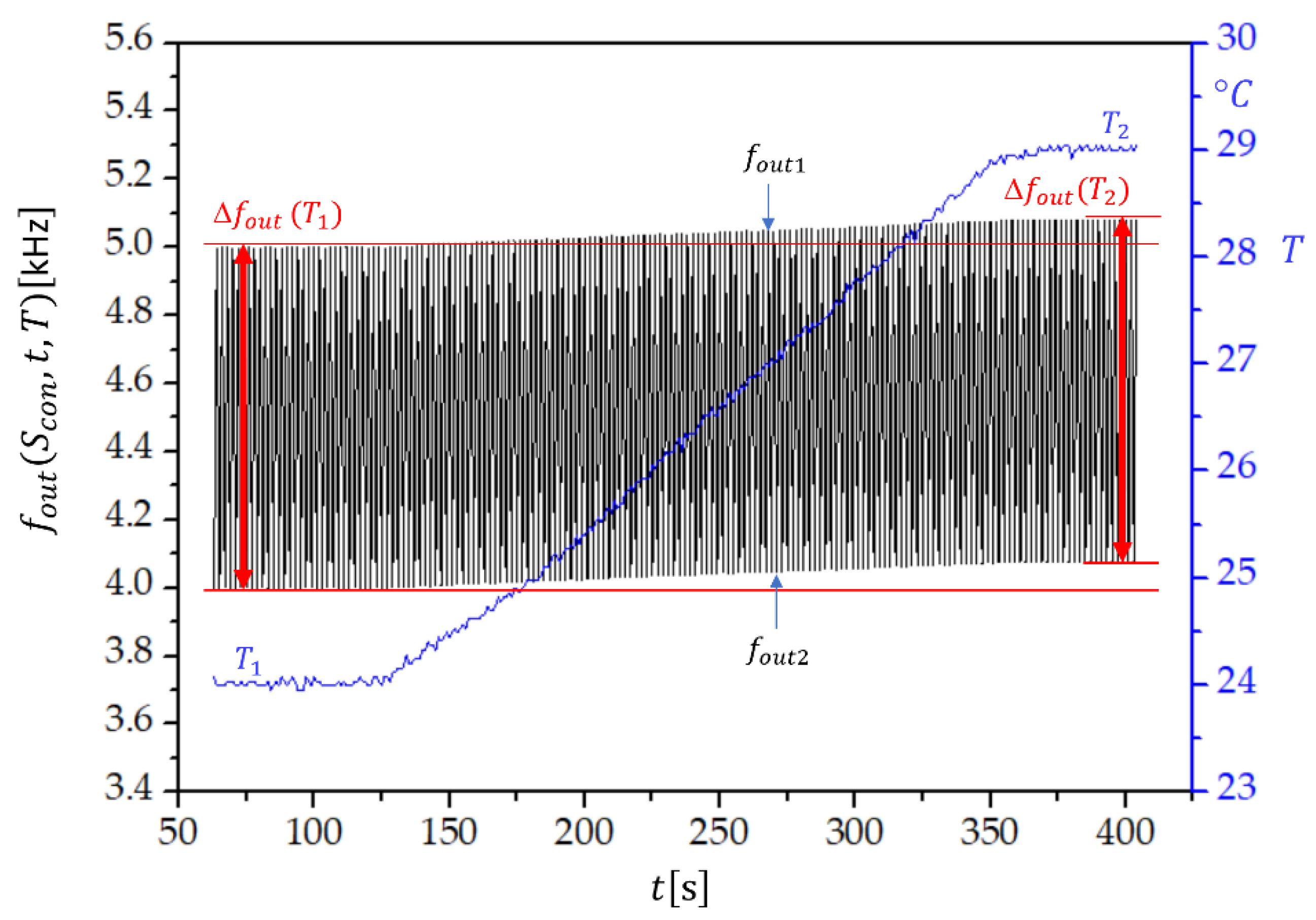
Figure 5 shows the switching mode extended dynamic stability, i.e., the frequency change of
, if the temperature of the sensor increases from
to
in the time span of 400 s. We see that the temperature change has an influence on
and
. However,
remains the same, which proves that the temperature influence on
,
, and
is compensated. Similarly, the influence of temperature change on the frequency measurement error produced by the frequency counter is significantly reduced. The dynamic temperature change of both frequencies is approximately the same. The temperature dependence of
, shown in
Figure 5, is universal for all the compensation factors. Its magnitude is set by the value of
.
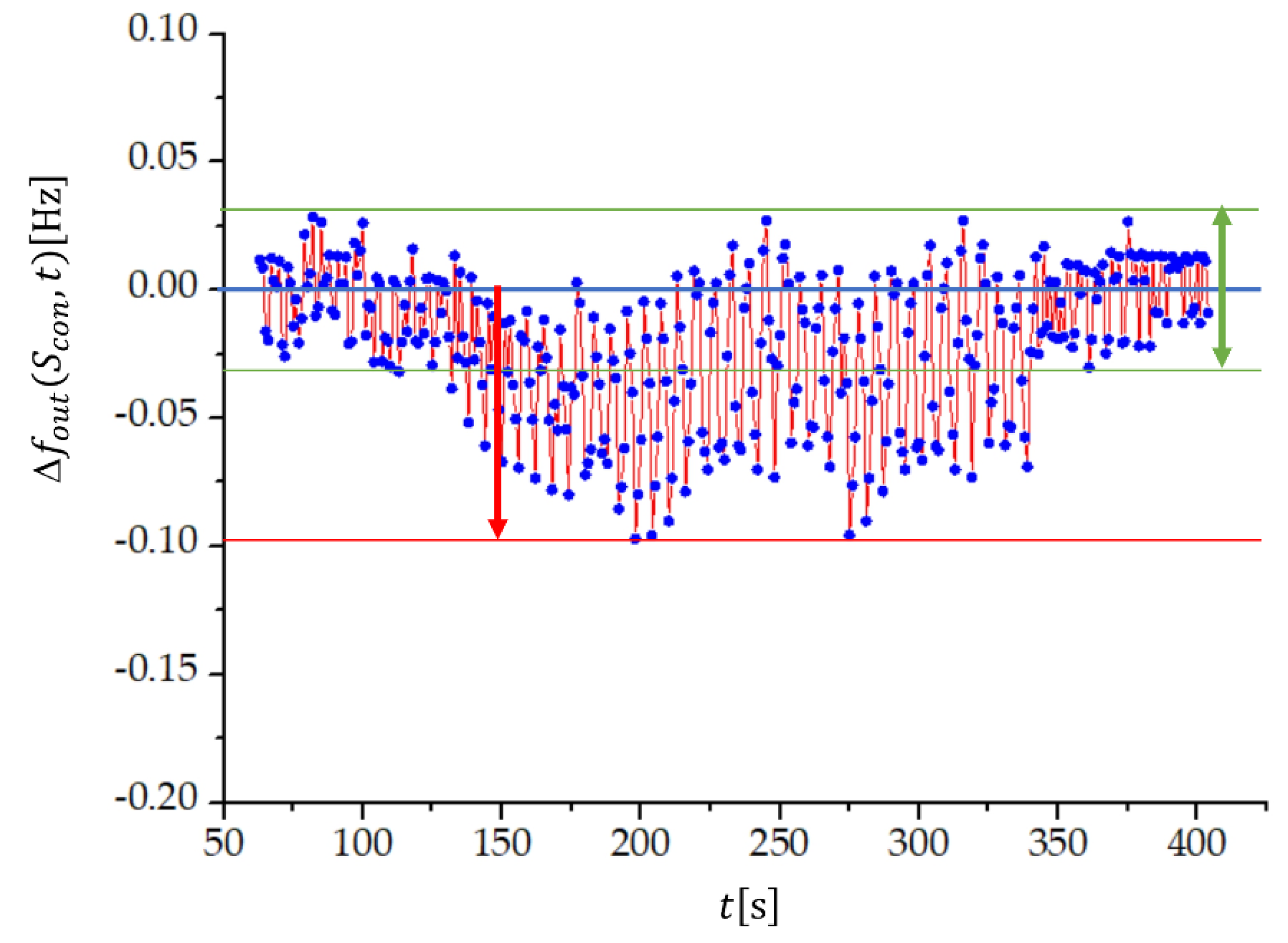
By including also the uncertainties in the measured frequencies,
equals
, where
and
are the uncertainties of the measured frequency differences
and
. The frequency stability at temperature variation can thus be conveniently studied at
, because in this case
. Measurements at
and
are shown in
Figure 6, but the characteristic is universal for all compensation factors and compensation inductances. We see that the uncertainty of the frequency difference is lower if the temperature is constant (green arrow in
Figure 6) and it is the same both at lower and higher temperature. When temperature is changing, the uncertainty increases (red arrow), but its value remains lower than
. In addition,
Figure 6 illustrates the temperature compensation of the quartz crystal’s natural temperature characteristics from
Figure 5.
Now we can return to results in
Table 1 and argue that the method enables measurements of changes in capacitance in a femtofarad range with a zeptofarad sensitivity, because a change in frequency as low as
can be measured if the temperature is changing (
Figure 6), and even lower (
) if the temperature is kept constant. The method is most sensitive if we have three quartz crystals, with the maximum compensation factor,
, at maximum compensation inductance,
From
Table 1 we see that, in this case, the sensitivity is
in a range of
. Thus, under a dynamic temperature condition one can detect changes in capacitance equal to
, which equals approximately
. At two quartz crystals, and the maximum
and
, we have
, which is approximately
, but over a 2.5-times wider capacitance sensing range,
, than in the case of three quartz crystals. If only one quartz crystal is used, then changes in capacitance
, i.e.,
, can be detected. We see that by connecting three quartz crystals in parallel, the sensitivity increases by an order of magnitude, while the capacitance sensing range reduces by an order of magnitude. Compared to other methods to detect low capacitance changes, which are not based on quartz crystals (an overview over these methods can be found in [
26,
29]), the here-proposed method offers a
to
times higher sensitivity.
5. Conclusions
We have presented a measuring method that employs several quartz crystals connected in parallel to measure small capacitance changes with a high accuracy and with the simultaneous compensation of several effects, especially compensation of the eigen frequency–temperature characteristics of the quartz crystals. This compensation is essential when the sensing (load) capacitance changes are in the fF or aF region. The presented method opens new applications in physics, chemistry, pharmacy, mechatronics, biosensor technology, and in all industrial applications that demand high-quality production.
The experimental circuit shown in
Figure 3 was used to reduce the effect of parasitic impedances, the temperature characteristics of the quartz crystals, the influence of dynamic changes in the environmental temperature, and the ageing of crystals and other elements in the circuit. The method also reduces the start-up time of the oscillator down to 1 min.
To detect very low changes in capacitance of the order of fF and aF, it is essential to compensate the parasitic capacitances, which was achieved by the switching mode method and the symmetry of the oscillator circuit. When frequencies and , obtained at two switches, are subtracted, we also subtract the effects of all the parasitic impedances. To have these effects as equal as possible at the two sequential switches, we used SPST 1–5 sequential switches. The circuit is made on an aluminium oxide PCB basis, which has a very low coefficient of thermal expansion (). The reference capacitor has a capacitance , which is approximately the same as the capacitance of the sensing (load) capacitance . In this way, equal conditions for crystals are achieved at both switches. The switching method also reduces the effect of the short- and long-term stability of the quartz oscillator. Next to the compensation of the temperature characteristics, the switching method also compensates the temperature instability of the reference oscillator because this effect is also subtracted after two sequential switches.
We have used AT-cut crystals with a -cut angle (the crystal’s cut axis is tilted by 35°15′ with respect to the optic axis), because these crystals have the lowest dependence of frequency on temperature ( in a temperature region ). The frequency was selected due to a higher Q value ). The switching method enables compensation of the AT-cut crystal temperature characteristics below in the temperature range . It was shown that this enables a zeptofarad resolution.
The main results, presented in
Table 1, show that a connection of two or three quartz crystals in parallel significantly increase the frequency–capacitance sensitivity, providing that the quartz crystals oscillate with the same frequency in the oscillator. The load (sensible) capacitance is connected in parallel to the quartz crystals. By increasing the number of quartz crystals connected in parallel, the sensitivity increases and the capacitance sensing range decreases. The sensitivity increases also by increasing the compensation factor, defined by the compensation inductance. For the performed measurements, the highest sensitivity,
, was achieved at a compensation factor
(
) and three quartz crystals in parallel. The capacitance sensing range in this case was
and the sensitivity
under a dynamic temperature variation. If temperature is kept constant, the sensitivity is even higher, approximately
.
To sum up, the advantages of the proposed measurement method based on the use of multiple quartz crystals connected in parallel are increased sensitivity; measuring range in the region with the resolution in the region; a sensitivity of in a sensing range of (for three quartz crystals in parallel, the maximum compensation factor and compensation inductance); high linearity of the frequency–capacitance characteristics within the sensing region; compensation of the temperature nonlinear characteristics of the crystal and oscillator elements; compensation of the ageing of crystals and other elements in the circuit; compensation of parasitic impedances; compensation of changes in the reference frequency; and compensation of the changes in the applied voltage. The output frequency is in the range of , which is the proper region for further processing of the signal by a microcontroller.


