Noise Resilient Outdoor Traffic Light Visible Light Communications System Based on Logarithmic Transimpedance Circuit: Experimental Demonstration of a 50 m Reliable Link in Direct Sun Exposure

 ,
, 
Abstract
1. Introduction
2. Debate on the Usage of the Visible Light Communication Technology in Automotive Applications: Issues and State of the Art Solutions
2.1. Optical Interferences Associated Issues and Solutions
2.2. Meteorological Conditions Associated Issues and Solutions
2.3. Long-Range Vehicular Communications State-of-the-Art
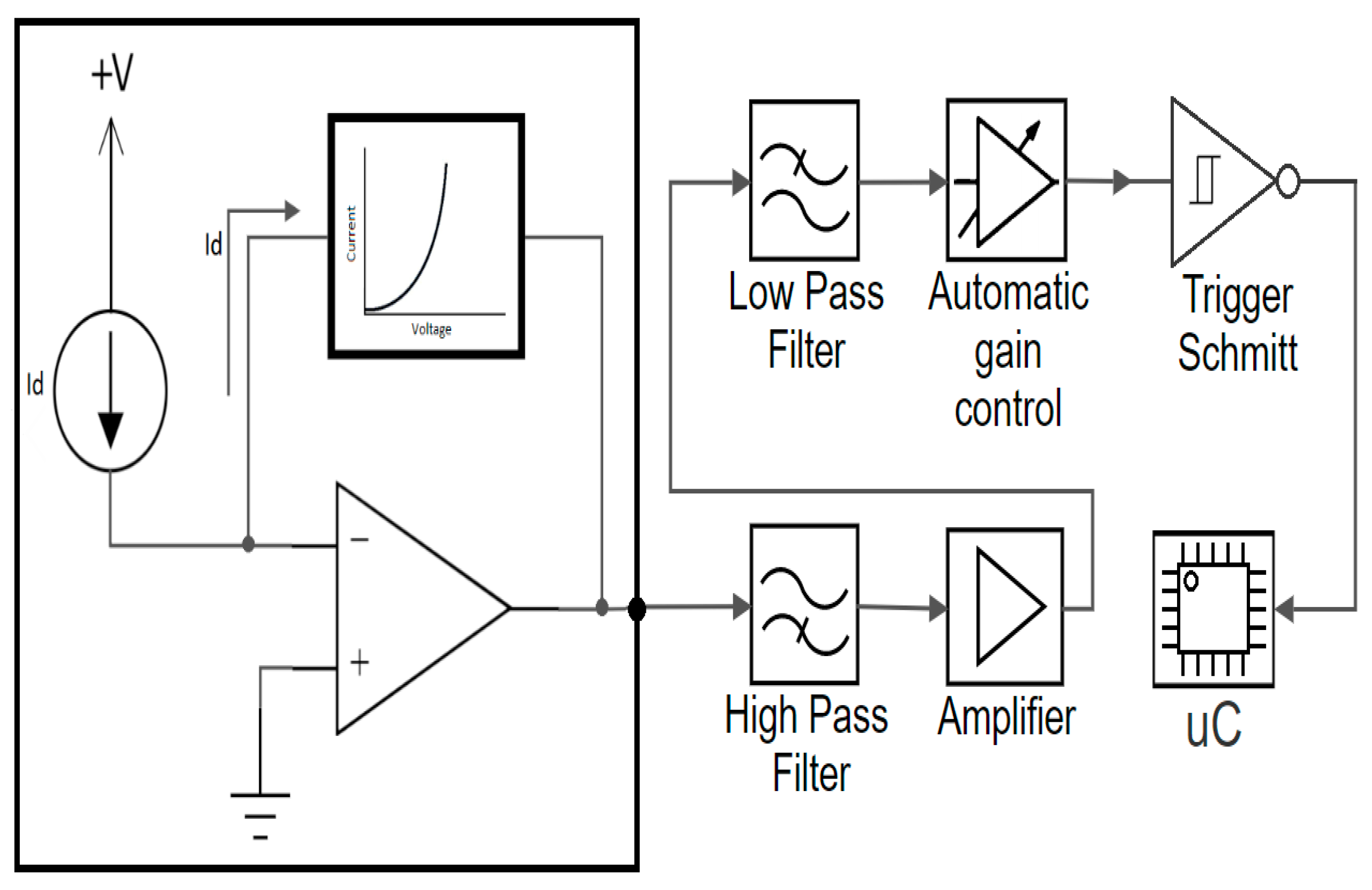
3. Considerations Regarding the Usage of Logarithmic Transimpedance Circuits in Automotive Visible Light Communications Sensors
4. Evaluation of the Logarithmic Transimpedance Circuit
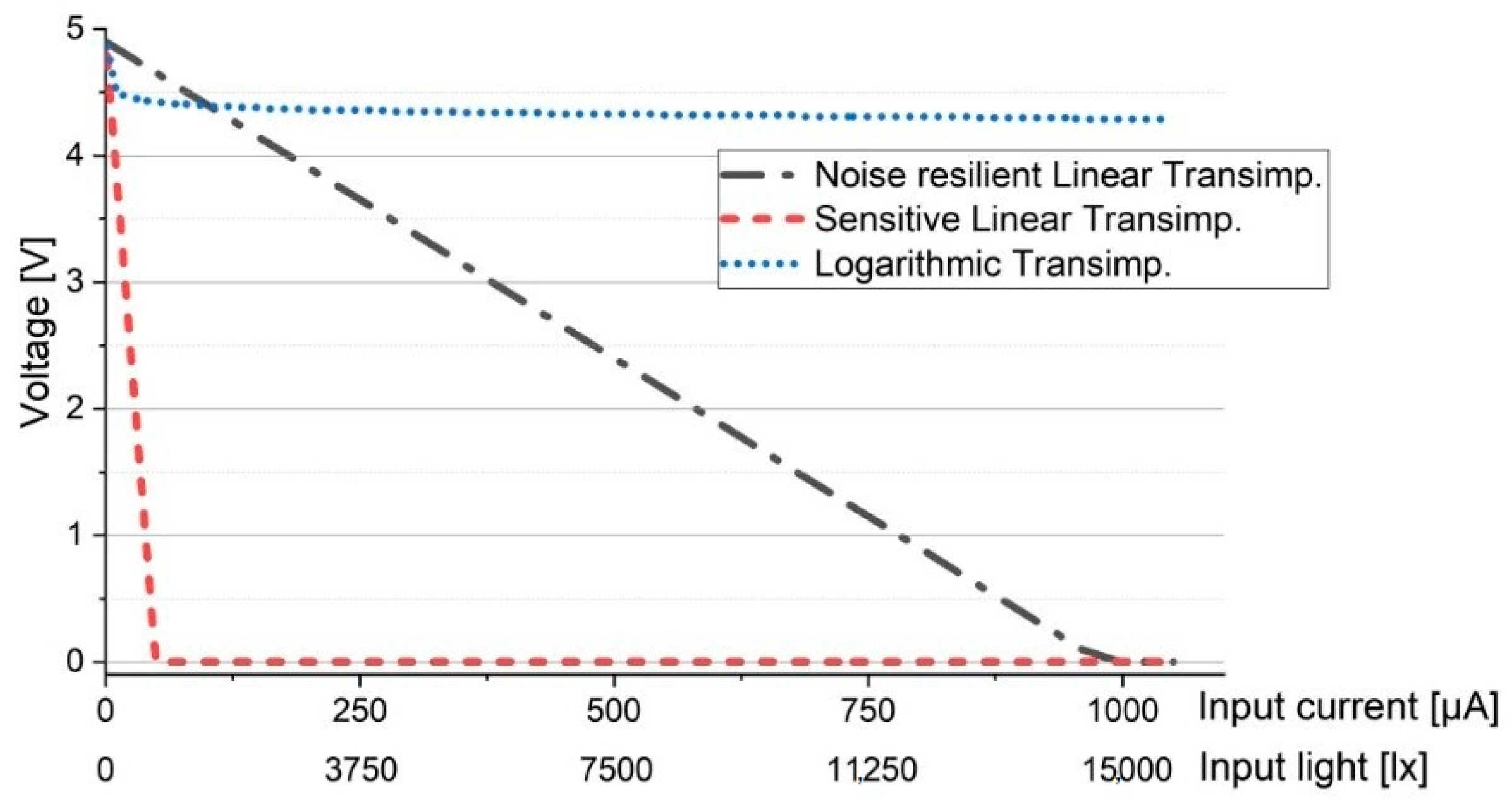
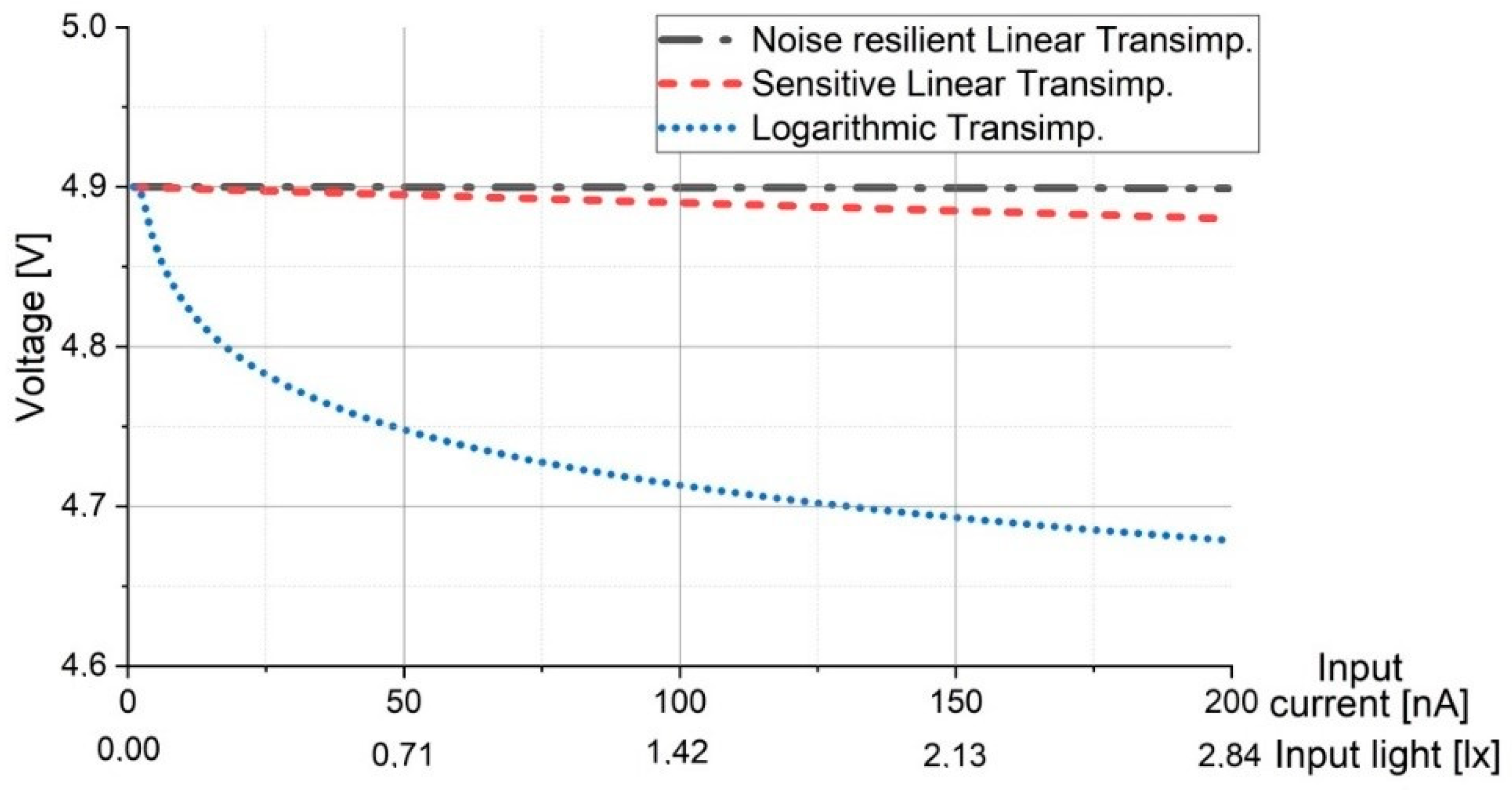
4.1. Analitical Evaluation of the Logarithmic Transimpedance Circuit and Its Comparison to Linear Circuit
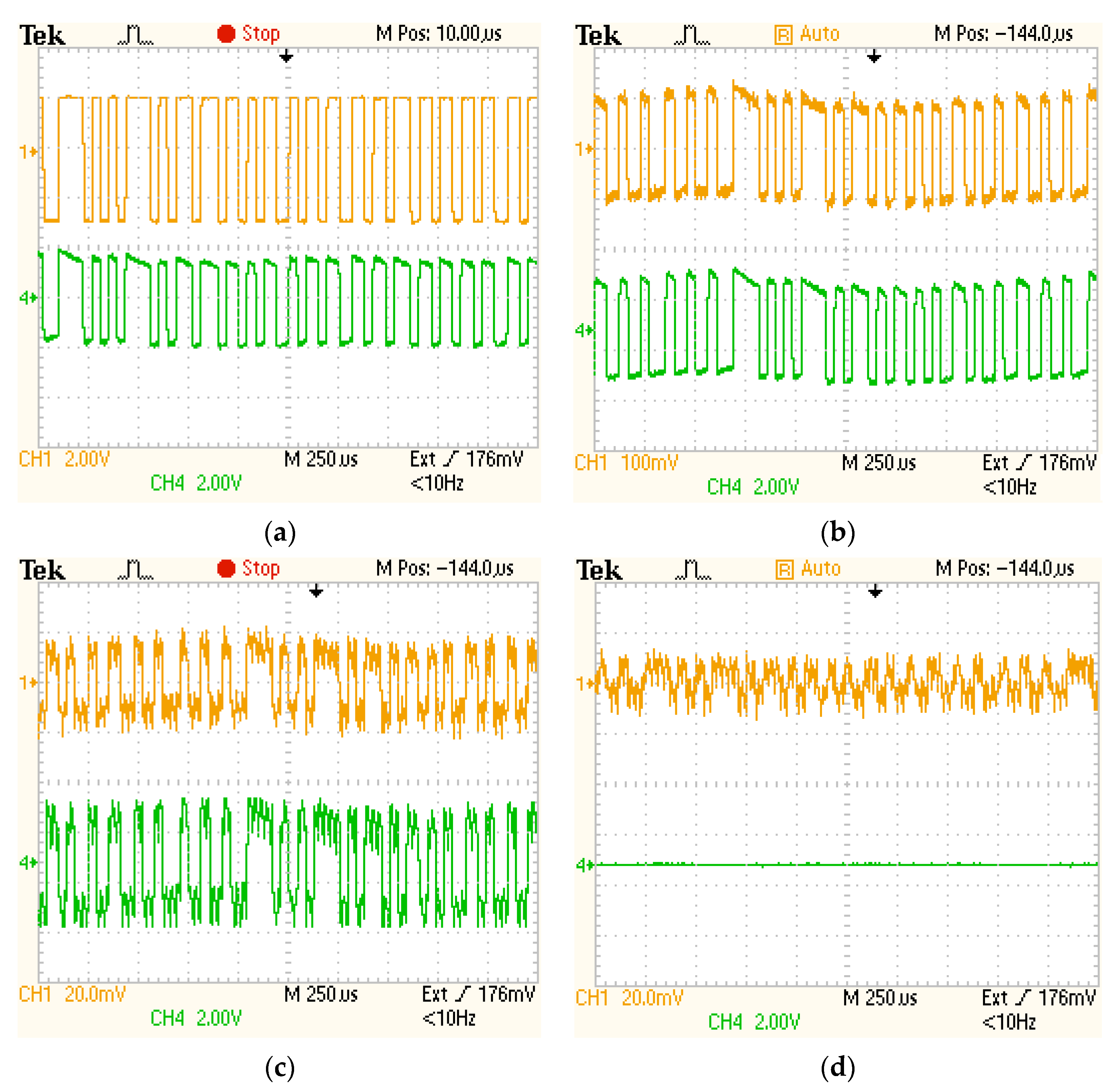
4.2. Experimental Evaluation in Strong Lighting Conditions: Confirming the Logarithmic Transimpedance Circuit Ability to Prevent the Saturation of the Photosensitive Element
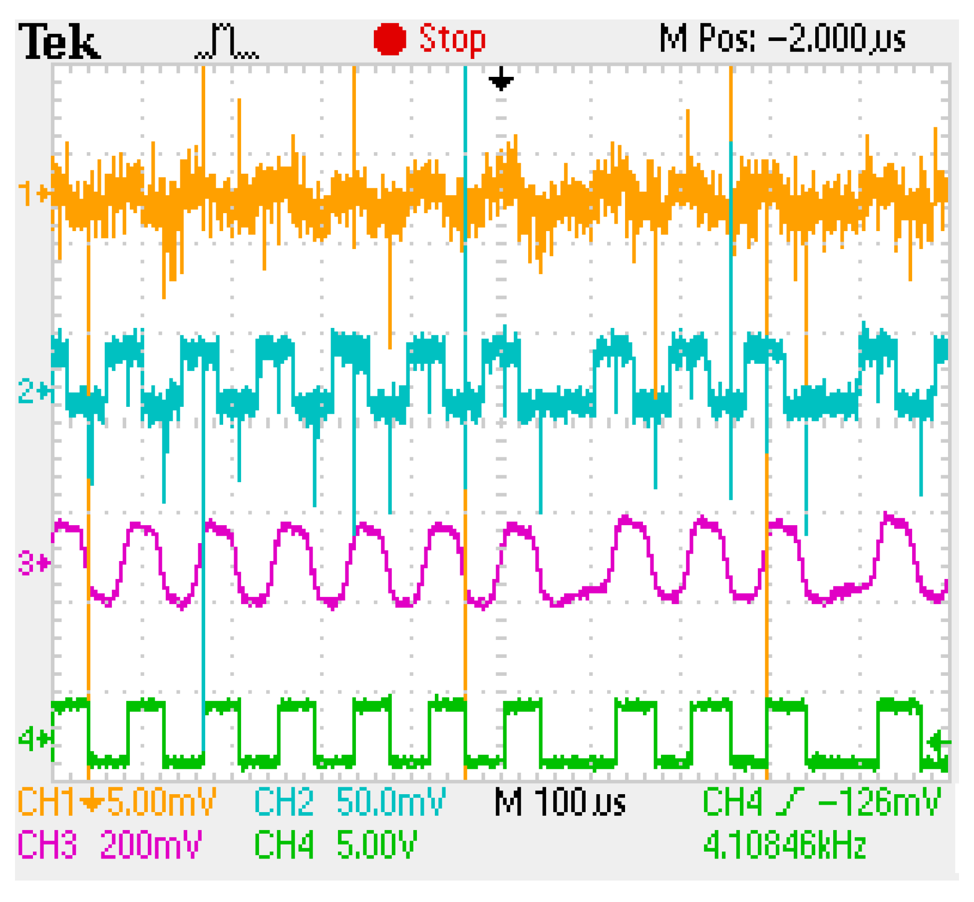
4.3. Experimental Evaluation of the Logarithmic Transimpedance Circuit: the Comparison with the Linear Circuit

| Parameter | Feature/Value |
|---|---|
| VLC emitter | Standard compliant LED-based traffic light: ELBA 3S1TL |
| Light source | 5 x High power red LEDs |
| Total LED power | 9W |
| Traffic light irradiance measured at 1 m | 190 μW/cm2 |
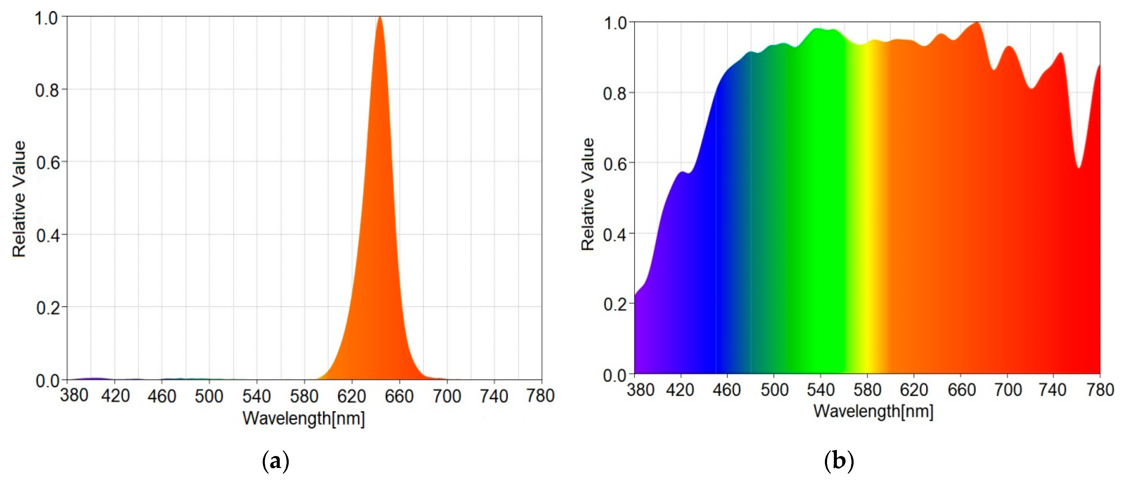
| LED central wavelength | 642 nm (see Figure 5a) |
| LED spectral width | 40 nm |
| Traffic light half angle | 15˚ |
| Traffic light diameter | 200 mm |
| Traffic light height | 200 cm |

4.4. Experimental Evaluation in Long Range Outdoor Conditions
- LED-based traffic light VLC emitter (see parameters in Table 6);
- Receiver FOV: 7,5°/15°/30°;
- Off the shelf IR-reject optical filter;
- Modulation type: OOK;
- Coding type: Manchester;
- Optical clock: 11 kHz;
- Asynchronous transmission;
- Emitter – Receiver distance: 50 m;
- Conditions: outdoor uncontrolled conditions; tests performed in different moments of the day in order to evaluate the impact of the sun for various optical power levels and relative orientations with respect to the VLC emitter;
- Measured parameters: real time BER determination;
5. Concluding Remarks Regarding the Experimental Evaluation of the VLC Sensor Based on Logarithmic Transimpedance Circuit and on Its Compatibility to Vehicular Communications
Debate on the Proposed Vehicular VLC System Performances
6. Conclusions
Author Contributions
Funding
Conflicts of Interest
References
- Pešek, P.; Zvanovec, S.; Chvojka, P.; Bhatnagar, M.R.; Ghassemlooy, Z.; Saxena, P. Mobile User Connectivity in Relay-Assisted Visible Light Communications. Sensors 2018, 18, 1125. [Google Scholar] [CrossRef] [PubMed]
- Căilean, A.M.; Dimian, M. Current Challenges for Visible Light Communications Usage in Vehicle Applications: A Survey. IEEE Commun. Surv. Tutor. 2017, 19, 2681–2703. [Google Scholar] [CrossRef]
- Matheus, L.E.M.; Vieira, A.B.; Vieira, L.F.M.; Vieira, M.A.M.; Gnawali, O. Visible Light Communication: Concepts, Applications and Challenges. IEEE Commun. Surv. Tutorials 2019, 21, 3204–3237. [Google Scholar] [CrossRef]
- Chowdhury, M.Z.; Hossan, M.T.; Islam, A.; Jang, Y.M. A Comparative Survey of Optical Wireless Technologies: Architectures and Applications. IEEE Access 2018, 6, 9819–9840. [Google Scholar] [CrossRef]
- Căilean, A.M.; Dimian, M. Impact of IEEE 802.15.7 Standard on Visible Light Communications Usage in Automotive Applications. IEEE Commun. Mag. 2017, 55, 169–175. [Google Scholar] [CrossRef]
- Shur, M.S.; Zukauskas, R. Solid-State Lighting: Toward Superior Illumination. Proc. IEEE 2005, 93, 1691–1703. [Google Scholar] [CrossRef]
- Azevedo, I.L.; Morgan, M.G.; Morgan, F. The Transition to Solid-State Lighting. Proc. IEEE 2009, 97, 481–510. [Google Scholar] [CrossRef]
- Cole, M.; Clayton, H.; Martin, K. Solid-State Lighting: The New Normal in Lighting. IEEE Trans. Ind. Appl. 2015, 51, 109–119. [Google Scholar] [CrossRef]
- Long, X.; He, J.; Zhou, J.; Fang, L.; Zhou, X.; Ren, F.; Xu, T. A review on light-emitting diode based automotive headlamps. Renew. Sustain. Energy Rev. 2015, 41, 29–41. [Google Scholar] [CrossRef]
- Ergen, M. Critical penetration for vehicular networks. IEEE Commun. Lett. 2010, 14, 414–416. [Google Scholar] [CrossRef]
- Kim, Y.H.; Cahyadi W., A.; Chung, Y.H. Experimental Demonstration of VLC-Based Vehicle-to-Vehicle Communications Under Fog Conditions. IEEE Photonics J. 2015, 7, 7905309. [Google Scholar] [CrossRef]
- Masini, B.M.; Bazzi, A.; Zanella, A. Vehicular Visible Light Networks for Urban Mobile Crowd Sensing. Sensors 2018, 18, 1177. [Google Scholar] [CrossRef] [PubMed]
- Cheng, L.; Viriyasitavat, W.; Boban, M.; Tsai, H. Comparison of Radio Frequency and Visible Light Propagation Channels for Vehicular Communications. IEEE Access 2018, 6, 2634–2644. [Google Scholar] [CrossRef]
- Shen, W.; Tsai, H. Testing vehicle-to-vehicle visible light communications in real-world driving scenarios. In Proceedings of the 2017 IEEE Vehicular Networking Conference (VNC), Torino, Italy, 27–29 November 2017; IEEE: Piscataway, NJ, USA, 2017; pp. 187–194. [Google Scholar] [CrossRef]
- Elamassie, M.; Karbalayghareh, M.; Miramirkhani, F.; Kizilirmak, R.C.; Uysal, M. Effect of Fog and Rain on the Performance of Vehicular Visible Light Communications. In Proceedings of the 2018 IEEE 87th Vehicular Technology Conference (VTC Spring), Porto, Portugal, 3–6 June 2018; IEEE: Piscataway, NJ, USA, 2018; pp. 1–6. [Google Scholar] [CrossRef]
- Islim, M.S.; Videv, S.; Safari, M.; Xie, E.; McKendry, J.J.; Gu, E.; Haas, H. The Impact of Solar Irradiance on Visible Light Communications. J. Lightwave Technol. 2018, 36, 2376–2386. [Google Scholar] [CrossRef]
- Rahaim, M.; Little, T.D.C. Interference in IM/DD optical wireless communication networks. IEEE/OSA J. Opt. Commun. Netw. 2017, 9, D51–D63. [Google Scholar] [CrossRef]
- Liu, C.; Sadeghi, B.; Knightly, E.W. Enabling vehicular visible light communication (V2LC) networks. Proc. ACM Vanet 2011, 41–50. [Google Scholar] [CrossRef]
- Chang, C.; Su, Y.; Kurokawa, U.; Choi, B.I. Interference Rejection Using Filter-Based Sensor Array in VLC Systems. IEEE Sens. J. 2012, 12, 1025–1032. [Google Scholar] [CrossRef]
- Căilean, A.M.; Cagneau, B.; Chassagne, L.; Dimian, M.; Popa, V. Novel Receiver Sensor for Visible Light Communications in Automotive Applications. IEEE Sens. J. 2015, 15, 4632–4639. [Google Scholar] [CrossRef]
- Căilean, A.M.; Dimian, M.; Popa, V.; Chassagne, L.; Cagneau, B. Novel DSP Receiver Architecture for Multi-Channel Visible Light Communications in Automotive Applications. IEEE Sens. J. 2016, 16, 3597–3602. [Google Scholar] [CrossRef]
- Căilean, A.M.; Dimian, M. Toward Environmental-Adaptive Visible Light Communications Receivers for Automotive Applications: A Review. IEEE Sens. J. 2016, 16, 2803–2811. [Google Scholar] [CrossRef]
- Avătămăniței, S.A.; Căilean, A.M.; Zadobrischi, E.; Done, A.; Dimian, M.; Popa, V. Intensive Testing of Infrastructure-to-Vehicle Visible Light Communications in Real Outdoor Scenario: Evaluation of a 50 m link in Direct Sun Exposure. In Proceedings of the 2019 Global LIFI Congress (GLC), Paris, France, 12–13 June 2019; IEEE: Piscataway, NJ, USA, 2019; pp. 1–5. [Google Scholar]
- Cerruela García, G.; Luque Ruiz, I.; Gómez-Nieto, M.Á. State of the Art, Trends and Future of Bluetooth Low Energy, Near Field Communication and Visible Light Communication in the Development of Smart Cities. Sensors 2016, 16, 1968. [Google Scholar] [CrossRef] [PubMed]
- Masini, B.M.; Bazzi, A.; Zanella, A. A Survey on the Roadmap to Mandate on Board Connectivity and Enable V2V-Based Vehicular Sensor Networks. Sensors 2018, 18, 2207. [Google Scholar] [CrossRef] [PubMed]
- Haas, H. LiFi is a paradigm-shifting 5G technology. Rev. Phys. 2018, 3, 26. [Google Scholar] [CrossRef]
- Ji, R.; Wang, S.; Liu, Q.; Lu, W. High-Speed Visible Light Communications: Enabling Technologies and State of the Art. Appl. Sci. 2018, 8, 589. [Google Scholar] [CrossRef]
- Do, T.-H.; Yoo, M. An in-Depth Survey of Visible Light Communication Based Positioning Systems. Sensors 2016, 16, 678. [Google Scholar] [CrossRef]
- Prince, G.B.; Little, T.D.C. Two-Phase Framework for Indoor Positioning Systems Using Visible Light. Sensors 2018, 18, 1917. [Google Scholar] [CrossRef]
- De-La-Llana-Calvo, Á.; Lázaro-Galilea, J.-L.; Gardel-Vicente, A.; Rodríguez-Navarro, D.; Bravo-Muñoz, I.; Espinosa-Zapata, F. Characterization of Multipath Effects in Indoor Positioning Systems by AoA and PoA Based on Optical Signals. Sensors 2019, 19, 917. [Google Scholar] [CrossRef]
- Kim, C.-M.; Koh, S.-J. Device Management and Data Transport in IoT Networks Based on Visible Light Communication. Sensors 2018, 18, 2741. [Google Scholar] [CrossRef]
- Balocco, C.; Volante, G. Lighting Design for Energy Sustainability, Information, and Perception. A Museum Environment as a Case Study. Sustainability 2018, 10, 1671. [Google Scholar] [CrossRef]
- Shahjalal, M.; Hasan, M.K.; Chowdhury, M.Z.; Jang, Y.M. Smartphone Camera-Based Optical Wireless Communication System: Requirements and Implementation Challenges. Electronics 2019, 8, 913. [Google Scholar] [CrossRef]
- Chowdhury, M.Z.; Shahjalal, M.; Hasan, M.K.; Jang, Y.M. The Role of Optical Wireless Communication Technologies in 5G/6G and IoT Solutions: Prospects, Directions, and Challenges. Appl. Sci. 2019, 9, 4367. [Google Scholar] [CrossRef]
- Cui, K.; Chen, G.; Xu, Z.; Roberts, R.D. Experimental characterization of traffic light to vehicle VLC link performance. In Proceedings of the 2011 IEEE GLOBECOM Workshops (GC Wkshps), Houston, TX, USA, 5–9 December 2011; IEEE: Piscataway, NJ, USA, 2011. [Google Scholar] [CrossRef]
- Islim, M.S.; Haas, H. An investigation of the solar irradiance effect on visible light communications. In Proceedings of the IEEE 28th Annual International Symposium on Personal, Indoor, and Mobile Radio Communications (PIMRC), Montreal, QC, Canada, 8–13 October 2017; IEEE: Piscataway, NJ, USA, 2017; pp. 1–6. [Google Scholar] [CrossRef]
- Cailean, A.; Cagneau, B.; Chassagne, L.; Topsu, S.; Alayli, Y.; Blosseville, J. Visible light communications: Application to cooperation between vehicles and road infrastructures. IEEE Intell. Veh. Symp. 2012, 1055–1059. [Google Scholar] [CrossRef]
- Kumar, N.; Lourenço, N.; Terra, D.; Alves, L.N.; Aguiar, R.L. Visible light communications in intelligent transportation systems. IEEE Intell. Veh. Symp. 2012, 748–753. [Google Scholar] [CrossRef]
- Pham, Q.N.; Rachim, V.P.; An, J.; Chung, W.-Y. Ambient Light Rejection Using a Novel Average Voltage Tracking in Visible Light Communication System. Appl. Sci. 2017, 7, 670. [Google Scholar] [CrossRef]
- Forkel, G.J.M.; Krohn, A.; Hoeher, P.A. Optical Interference Suppression Based on LCD-Filtering. Appl. Sci. 2019, 9, 3134. [Google Scholar] [CrossRef]
- Martinek, R.; Danys, L.; Jaros, R. Visible Light Communication System Based on Software Defined Radio: Performance Study of Intelligent Transportation and Indoor Applications. Electronics 2019, 8, 433. [Google Scholar] [CrossRef]
- Zaki, R.W.; Fayed, H.A.; Abd El Aziz, A.; Aly, M.H. Outdoor Visible Light Communication in Intelligent Transportation Systems: Impact of Snow and Rain. Appl. Sci. 2019, 9, 5453. [Google Scholar] [CrossRef]
- Ebrahim, K.J.; Al-Omary, A. Sandstorm Effect on Visible Light Communication. In Proceedings of the 2017 9th IEEE-GCC Conference and Exhibition (GCCCE), Manama, Bahrain, 8–11 May 2017; IEEE: Piscataway, NJ, USA, 2017; pp. 1–7. [Google Scholar] [CrossRef]
- Guan, W.; Li, J.; Wen, S.; Zhang, X.; Ye, Y.; Zheng, J.; Jiang, J. The Detection and Recognition of RGB-LED-ID Based on Visible Light Communication using Convolutional Neural Network. Appl. Sci. 2019, 9, 1400. [Google Scholar] [CrossRef]
- Wang, C.; Liu, Y.; Li, W.; Wang, F.; Chi, N. A 375Mb/s Real-time Internet of Vehicles System Based on Automotive Headlight Utilizing OFDM-64QAM Modulation Format. In Proceedings of the 18th International Conference on Optical Communications and Networks (ICOCN), Huangshan, China, 5–8 August 2019; IEEE: Piscataway, NJ, USA, 2019; pp. 1–3. [Google Scholar] [CrossRef]
- Han, S.; Wang, C.; Li, G.; Chi, N. A 427.5 Mbps Automotive Headlight Visible Light Communication System Utilizing 64QAM-DMT Modulation with Software Pre-equalization. In Proceedings of the IEEE/CIC International Conference on Communications in China (ICCC), Changchun, China, 11–13 August 2019; IEEE: Piscataway, NJ, USA, 2019; pp. 169–172. [Google Scholar] [CrossRef]
- Eso, E.; Ghassemlooy, Z.; Zvanovec, S.; Gholami, A.; Burton, A.; Hassan, N.B.; Younus, O.I. Experimental Demonstration of Vehicle to Road Side Infrastructure Visible Light Communications. In Proceedings of the 2nd West Asian Colloquium on Optical Wireless Communications, Tehran, Iran, 27–28 April 2019; IEEE: Piscataway, NJ, USA, 2019; pp. 85–89. [Google Scholar] [CrossRef]
- Liu, Y.; Shiu, R.; Wei, L.; Hsu, C.; Chow, C.; Yeh, C. 100-m Long Distance RGB Visible Light Camera Communication. In Proceedings of the 23rd Opto-Electronics and Communications Conference, Jeju Island, Korea, 2–6 July 2018; IEEE: Piscataway, NJ, USA, 2018; pp. 1–2. [Google Scholar] [CrossRef]
- Liu, W.; Xu, Z. Predicted and Experimental Performance of a Long Distance Non-Line of Sight Image Sensor Communication System. In Proceedings of the 2018 IEEE International Conference on Communications Workshops (ICC Workshops), Kansas City, MO, USA, 20–24 May 2018; IEEE: Piscataway, NJ, USA, 2018; pp. 1–6. [Google Scholar] [CrossRef]
- Zhang, Y.; Zhang, M.; Zhou, H.; Sun, Y.; Wei, C.; He, W. A Long Distance Real-time DPSK Visible Light Communication System Based on FPGA. In Proceedings of the 18th International Conference on Optical Communications and Networks, Huangshan, China, 5–8 August 2019; IEEE: Piscataway, NJ, USA, 2019; pp. 1–3. [Google Scholar] [CrossRef]
- Nawaz, T.; Seminara, M.; Caputo, S.; Mucchi, L.; Cataliotti, F.S.; Catani, J. IEEE 802.15.7-Compliant Ultra-Low Latency Relaying VLC System for Safety-Critical ITS. IEEE Trans. Veh. Technol. 2019, 68, 12040–12051. [Google Scholar] [CrossRef]
- Béchadergue, B.; Chassagne, L.; Guan, H. Simultaneous Visible Light Communication and Distance Measurement Based on the Automotive Lighting. IEEE Trans. Intell. Veh. 2019, 4, 532–547. [Google Scholar] [CrossRef]
- Kahn, J.M.; Barry, J.R. Wireless infrared communications. Proc. IEEE 1997, 85, 265–298. [Google Scholar] [CrossRef]
- Dimian, M.; Andrei, P. Noise-Driven Phenomena in Hysteretic Systems; Springer-Verlag: New York, NY, USA, 2014; pp. 1–233. ISBN 978-1-4614-1374-5. [Google Scholar]


| Perturbation Source | Effects | Solutions | Solution Complexity |
|---|---|---|---|
| Perturbations introduced by Natural and artificial light sources | |||
| Incandescent lighting sources | 100 Hz perturbation and its harmonics | High pass filters; | Low |
| Fluorescent lighting sources | 100 Hz perturbation and its harmonics | High pass filters; | Low |
| Sunlight | Photoelement saturation | Difficult to address; | High |
| Strong DC component | High pass filters; Optical filters [16,36]; | Low | |
| Strong shot noise (high frequency) component | Lowpass/bandpass filters; Noise subtractor [39]; Optical interference suppression based on LCD filtering [40]; Complex digital signal processing; | Moderate - high | |
| Perturbations introduced by Whether/atmospheric phenomena | |||
| Rain and Fog | Reflection, refraction, absorption, scattering – all leading to Signal Attenuation | Fresnel lens and multiple photodiodes [11]; | Low |
| Environment-adaptive features [22]; | High | ||
| Snow | Light blockage, Attenuation | Large reception area, focal lens, multiple photodiodes [11]; | Low |
| Dust | |||
| Perturbations introduced by the vehicular environment | |||
| Mobility | Strong variations of the emitter – receiver distance, Loss of connectivity; | Field of View Adaptivity; Automatic gain control; | Low to Moderate |
| Unpredictability | Loss of connectivity; | Context-adaptivity [22]. | High |
| Parameter | Value/Feature |
|---|---|
| Photodiode Type | BPX 61 |
| Photodiode Capacity | 72 pF |
| Photodiode Photocurrent | 70 nA/lux |
| Photodiode Surface | 7.02 mm2 |
| Light Illuminance | 0–15.000 lux |
| Photodiode Switching Time | 20 ns |
| Operational Amplifier Supply Voltage | 5 V |
| Bias Voltage Non-inverting Input | 4.9 V |
| Transimpedance solutions: | Logarithmic |
| High sensitive linear circuit (Rload = 100 kΩ) Noise resilient linear circuit (Rload = 4.5 kΩ) |
| Parameter | Feature/Value |
|---|---|
| Transimpedance circuit | Logarithmic |
| Photodiode type | BPX 61 |
| Photodiode Capacity | 72 pF |
| Photodiode Photocurrent | 70 nA/lux |
| Photodiode surface | 7.02 mm2 |
| Photodiode Spectral range | 400–1100 nm |
| Photodiode switching time | 20 ns |
| Photodiode Sensitive area | 7.02 mm2 |
| Photodiode Half angle | ±55˚ |
| Photodiode Spectral sensitivity | 0.62 A/W |
| Incident irradiance | 0–15.000 μW/cm2 |
| Parameter | Feature/Value |
|---|---|
| Light source | High power white LED |
| LED power | 5 W |
| LED Correlated color temperature | 5128 K |
| Equipment Type | Equipment |
|---|---|
| Spectral analyzer | Sekonic C800 |
| Irradiance meter | Delta Ohm HD 2302.0 with LP 471 RAD Probe |
| Oscilloscope | Tektronix TBS 1064 |
| Sunlight Irradiance at Sensor Level [μW/cm2] | VLC Receiver FOV | Average BER | Uncontrolled Outdoor Conditions |
|---|---|---|---|
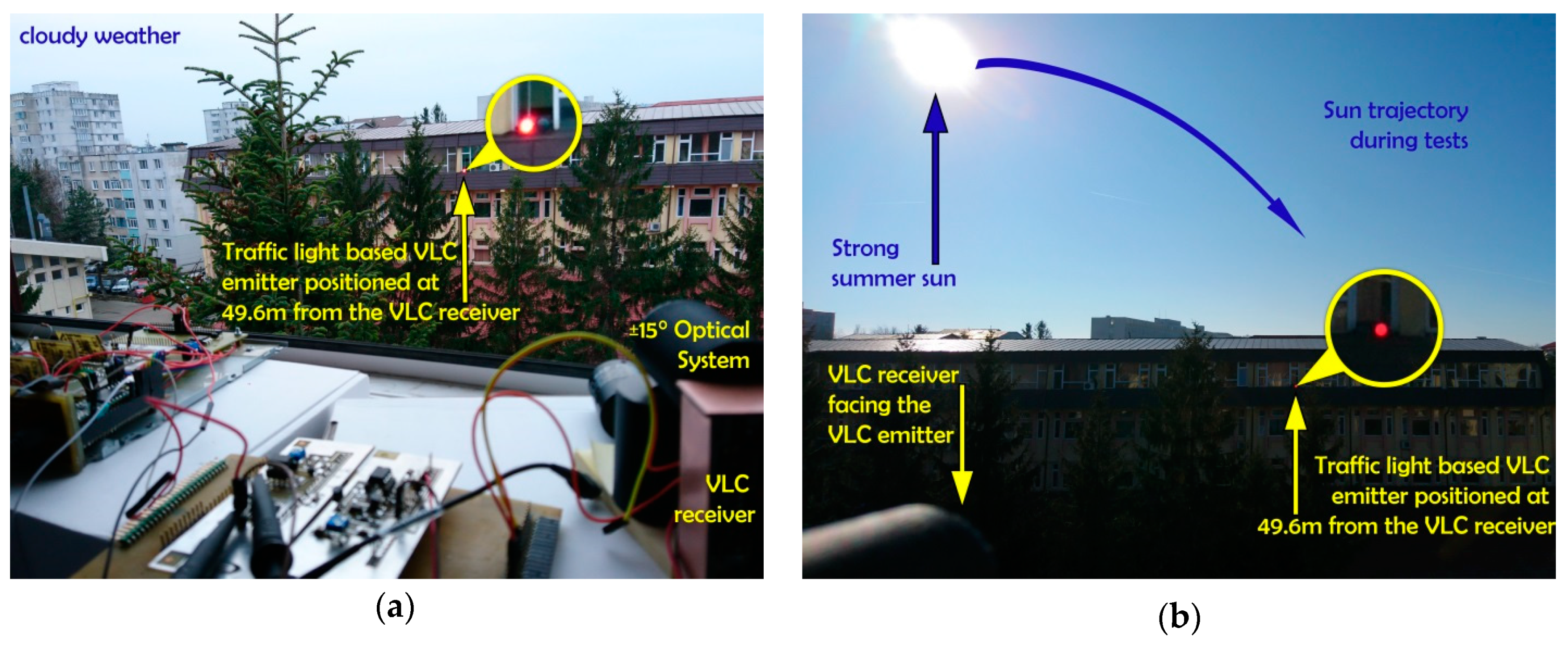
| 1500 –2200 | 30° | <10−6 | Cloudy afternoon |
4000 –4500 | 30° | ≈10−4 | Bright day, with no direct visibility of the sun. See Figure 7a |
| 12,000 –17,500 | 7.5° | <10−6 | The sun sets and its irradiance is gradually decreasing. |
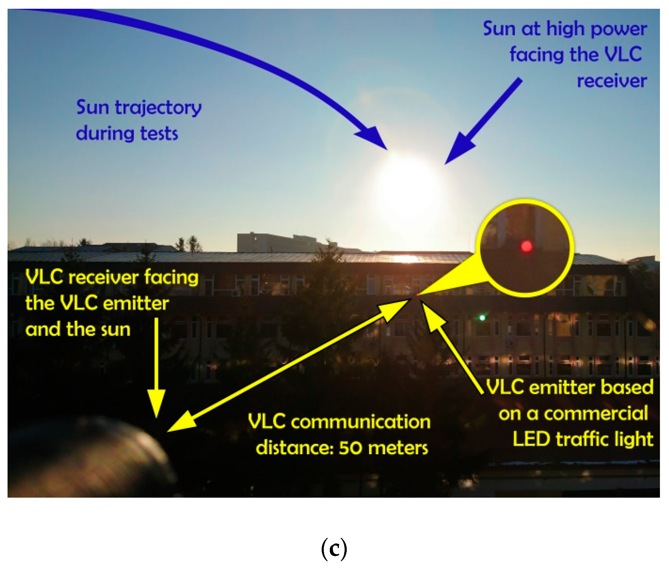
| 25,000 –50,000 | 7.5° | 10−4–10−6 | Bright sun conditions, with no clouds. The sun is located right above the VLC emitter, directly facing the VLC receiver. Worst case scenario for VLC. See Figure 7c |
| 63,000 –67,250 | 15° | 10−3–10−5 | Bright sun conditions, with no clouds. The sun was initially located left of the VLC receiver; As it travels the sky, toward sunset, its influence on the VLC receiver increases, which explains the variable BER. In this setup, the sun is not directly facing the VLC receiver. The sun is on the same axis with the VLC systems, facing the receiver. See Figure 7b |
© 2020 by the authors. Licensee MDPI, Basel, Switzerland. This article is an open access article distributed under the terms and conditions of the Creative Commons Attribution (CC BY) license (http://creativecommons.org/licenses/by/4.0/).
Share and Cite
Avătămăniței, S.A.; Căilean, A.-M.; Done, A.; Dimian, M.; Prelipceanu, M. Noise Resilient Outdoor Traffic Light Visible Light Communications System Based on Logarithmic Transimpedance Circuit: Experimental Demonstration of a 50 m Reliable Link in Direct Sun Exposure. Sensors 2020, 20, 909. https://doi.org/10.3390/s20030909
Avătămăniței SA, Căilean A-M, Done A, Dimian M, Prelipceanu M. Noise Resilient Outdoor Traffic Light Visible Light Communications System Based on Logarithmic Transimpedance Circuit: Experimental Demonstration of a 50 m Reliable Link in Direct Sun Exposure. Sensors. 2020; 20(3):909. https://doi.org/10.3390/s20030909
Chicago/Turabian StyleAvătămăniței, Sebastian Andrei, Alin-Mihai Căilean, Adrian Done, Mihai Dimian, and Marius Prelipceanu. 2020. "Noise Resilient Outdoor Traffic Light Visible Light Communications System Based on Logarithmic Transimpedance Circuit: Experimental Demonstration of a 50 m Reliable Link in Direct Sun Exposure" Sensors 20, no. 3: 909. https://doi.org/10.3390/s20030909
APA StyleAvătămăniței, S. A., Căilean, A.-M., Done, A., Dimian, M., & Prelipceanu, M. (2020). Noise Resilient Outdoor Traffic Light Visible Light Communications System Based on Logarithmic Transimpedance Circuit: Experimental Demonstration of a 50 m Reliable Link in Direct Sun Exposure. Sensors, 20(3), 909. https://doi.org/10.3390/s20030909