Review

Recent Progress on Electromagnetic Field Measurement Based on Optical Sensors

1
School of Mechanical Engineering, Xi’an Jiaotong University, Xi’an 710049, China
2
State Key Laboratory of Power Grid Environmental Protection, China Electric Power Research Institute, Wuhan 430074, China
*
Author to whom correspondence should be addressed.
Sensors 2019, 19(13), 2860; https://doi.org/10.3390/s19132860
Submission received: 5 May 2019 / Revised: 13 June 2019 / Accepted: 20 June 2019 / Published: 27 June 2019
(This article belongs to the Special Issue Fiber-Based Sensing Technology: Recent Progresses and New Challenges)

Abstract

:
Electromagnetic field sensors are widely used in various areas. In recent years, great progress has been made in the optical sensing technique for electromagnetic field measurement, and varieties of corresponding sensors have been proposed. Types of magnetic field optical sensors were presented, including probes-based Faraday effect, magnetostrictive materials, and magnetic fluid. The sensing system-based Faraday effect is complex, and the sensors are mostly used in intensive magnetic field measurement. Magnetic field optical sensors based on magnetic fluid have high sensitivity compared to that based on magnetostrictive materials. Three types of electric field optical sensors are presented, including the sensor probes based on electric-optic crystal, piezoelectric materials, and electrostatic attraction. The majority of sensors are developed using the sensing scheme of combining the LiNbO3 crystal and optical fiber interferometer due to the good electro-optic properties of the crystal. The piezoelectric materials-based electric field sensors have simple structure and easy fabrication, but it is not suitable for weak electric field measurement. The sensing principle based on electrostatic attraction is less commonly-used sensing methods. This review aims at presenting the advances in optical sensing technology for electromagnetic field measurement, analyzing the principles of different types of sensors and discussing each advantage and disadvantage, as well as the future outlook on the performance improvement of sensors.

1. Introduction

Electromagnetic field (EMF) sensors have been drawing attention in recent years because of these wide usages in various areas, including navigation and medical instruments, and the power industry. For example, in magnetic resonance imaging diagnostics, magnetic field sensors are used for magnetic resonance data acquisition and assessment of magnetic radiation risk to protect workers from heavy occupational exposure [1,2,3]. Electromagnetic sensors are an effective tool to diagnose the troubles and ensure electronic equipment safety and stable operation in the power grid [4,5].
One type of conventional magnetic field sensors, a common tesla meter, consists of a hall sensor probe and a dashboard, which is not sensitive enough to measure the weak magnetic field (<1 mT) [6,7]. Another type of sensors consists of a coil with hundreds of fine-gage wires. When placed in an alternating magnetic field, an induced current is proportional to the strength of the applied magnetic field, which is not applicable to a static magnetic field. A commonly-used method for electric field measurement is based on a displacement current sensor which consists of two thinly-conductive plates connected together electrically. Another type of electric sensor is composed of a shield sector sheet and a fixed induction metal sheet. In the presence of an electric field, the shield sector sheet rotating the fixed metal sheet generates an induced current. The induced current is measured to derive electric field strength. The above methods have to use the metal antennas or probes to induce the electric field [8,9]. The metallic structures are susceptible to electromagnetic noise and can only measure EMF at a single point.
Optical sensors have a number of advantages over conventional sensing techniques, such as compact size, strong adaptability to harsh environments, and immunity to electromagnetic interference, so lots of work has focused on EMF optical sensors in the decades at the end of last century [10,11,12]. One type of optical sensors are bulk sensors, which are integrated by a fiber with the field transducers, such as magneto-optic crystal, magnetostrictive materials, magnetic fluid, electro-optic crystals, and piezoelectric ceramics. The other type of sensor is an all-fiber sensor, where the fiber is not only used for light guiding but the sensing element. The all-fiber sensors for magnetic field measurement are based on the Faraday effect of magneto-optic fiber. The electric field all-fiber sensors are based on the electrostrictive effect of silica fiber, which is rarely used due to the low-sensitivity to electric field. Over the past decades, as the advances of new functional materials, such as magneto optic fiber, giant magnetostrictive materials, and magnetic fluid, the optical sensing technology for EMF has made great progress. The optical sensing technology also has a rapid development, especially the optical fiber sensing technique. There is a report about the optic fiber magnetic field sensor based on MF [13], but to our knowledge, no reviews specifically pay attention to the development of EMF optical sensors in the past ten years. Therefore, this paper aims to provide a summarized overview of the various types of EMF optical sensors.

2. Magnetic Field Optical Sensors

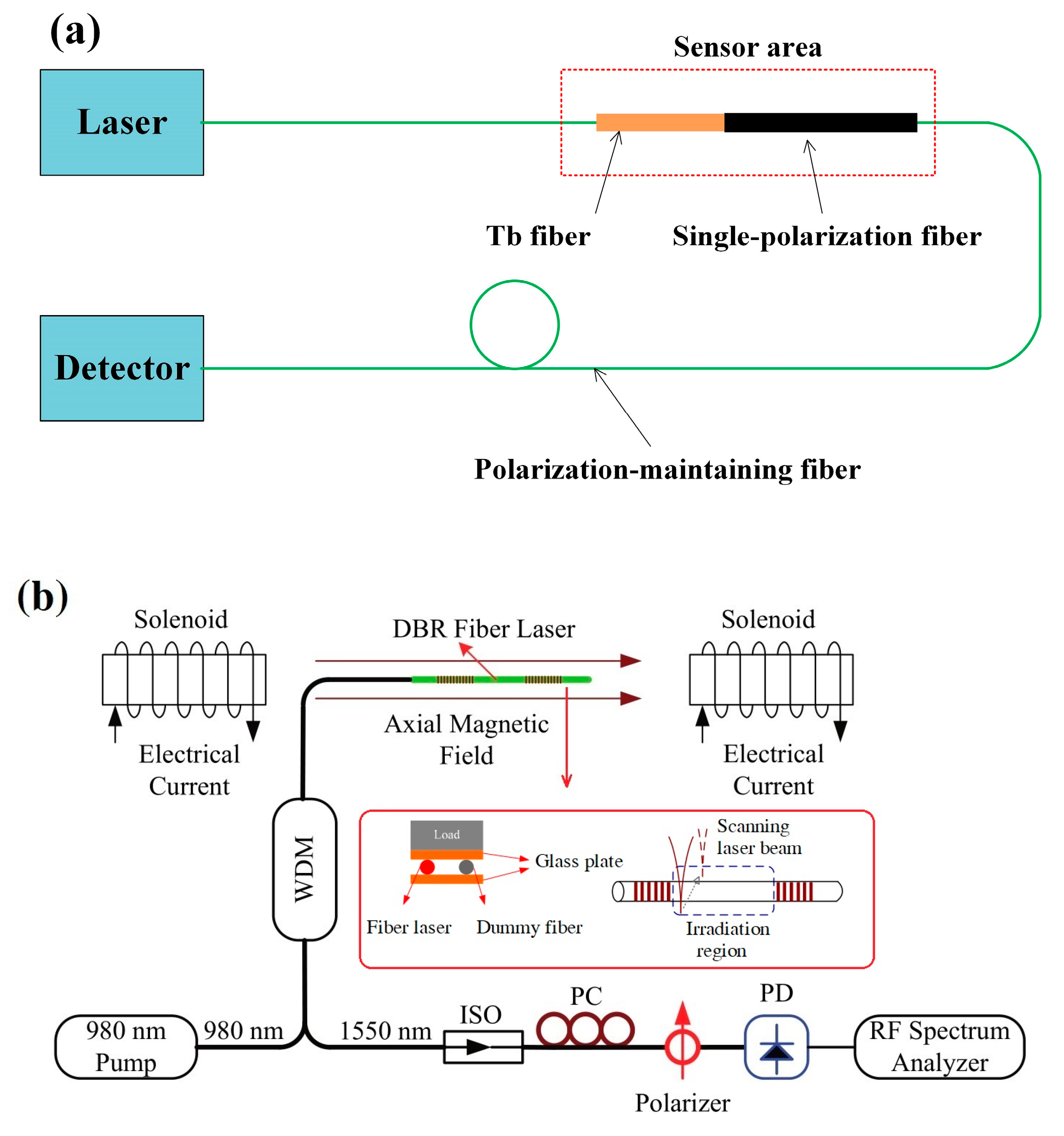
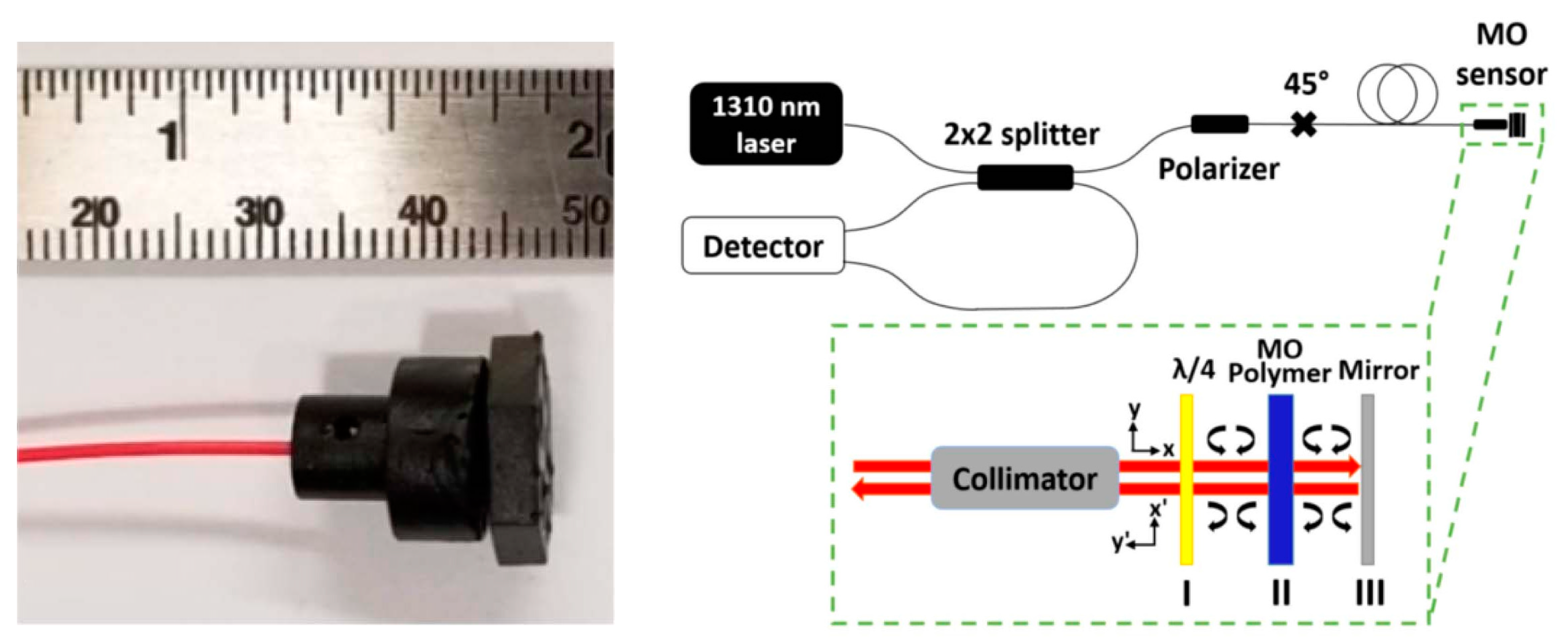
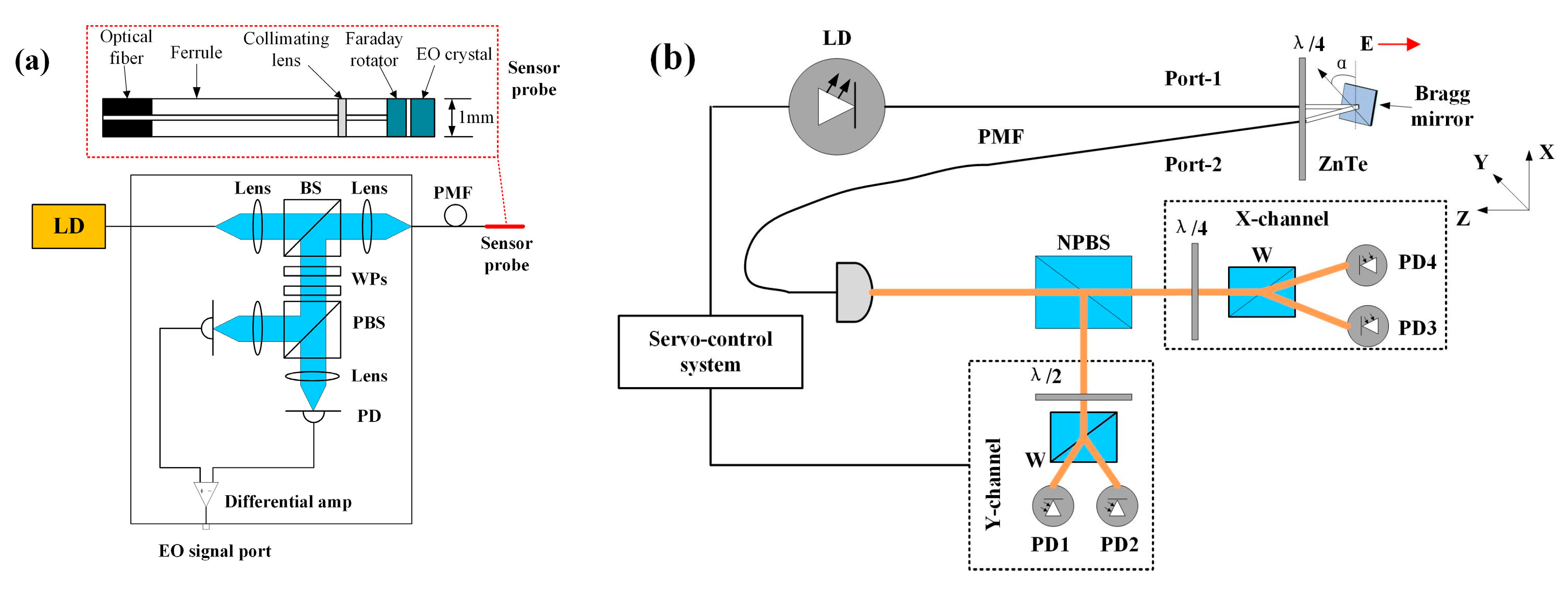
2.1. Probes Based on the Faraday Effect

The Faraday effect is a magneto-optical phenomenon—that is, an interaction between light and a magnetic field in a medium. The Faraday effect causes a rotation for the plane of polarization when plane-polarized light passes through a substance placed in a magnetic field. For a given substance, the rotation angle is proportional to the length traversed by the light and the magnetic field strength, which can be expressed as in [14]:
θ = V 0 l B ( l ) d l
where, θ is the rotation angle, V is the Verdet constant of a given substance or a function of concentration, temperature, and frequency, B is the magnetic flux density (B = μ·H, H the magnetic field strength), and l is the length over which the magnetic field and light interact.
Sun et al. proposed an all-fiber optical magnetic-field sensor based on the Faraday rotation in terbium-doped (Tb) fiber. The Verdet constant of the Tb fiber is about 20 times larger than that of silica fiber, so this sensor probe has a higher sensitivity. Linear-polarized light is transmitted to the Tb fiber through polarization-maintaining fiber (PMF). The polarization of light rotates when the Tb fiber is placed in a magnetic field. The polarization rotation angle is related to the magnetic field strength, so the magnetic field can be measured by monitoring the output light intensity. The probe configuration and sensing system are shown in Figure 1a [15]. Some magnetic field sensors were designed using a heterodyning fiber grating laser. When a magnetic field is applied to the fiber grating laser, the birefringence in the fiber grating laser cavity becomes an elliptical birefringence. The Faraday rotation effect induces the circular birefringence into the cavity. The beat frequency of signal generated by two orthogonally polarized laser outputs is related to the magnetic field intensity [16,17,18]. In order to enhance the sensitivity of these magnetic sensors, Cheng et al. achieved the sensitivity enhancement by transverse force action or CO2-laser treatment to change the linear birefringence, as illustrated in Figure 1b [19]. Han et al. positioned a silicon steel sheet close to the fiber grating laser to strengthen the magnetic field intensity around the fiber grating laser cavity, wherein the silicon steel sheet worked as a magnetic field concentrator [20].
Descamps et al. proposed a magnetic field sensing method through detection of the circular birefringence of optical fiber induced by the Faraday effect. In an applied magnetic field, the FBG polarization properties, such as polarization dependent loss (PDL) and differential group delay (DGD), are changed. The magnetic field strength can be obtained by computing the diattenuation vector. It is a new demodulation technique allowing the use of a FBG written in common single-mode fiber (SMF) [21]. Amirsolaimani et al. developed a high sensitivity magnetometer using nanocomposite polymers, as shown in Figure 2. The Faraday rotation inside the nanocomposite generates the phase shift between two orthogonal polarization lights. The nanocomposite polymers were fabricated by encapsulating the Dy3+-doped magnetite and cobalt ferrite nanoparticles within polymethylmethacrylate matrix. The nanocomposite has a high Verdet constants (6.6 × 10⁶ °/T·m), which is about 105 times larger than that of common silica fiber. Additionally, the design of a double optical path through the magneto-optic polymer enhances the Faraday rotation. In the contribution of the magneto-optic polymer with high Verdet constants and the double optical path design, the sensor can achieve a high sensitivity of 20 fT/√Hz. This sensing scheme can be used for detecting neuronal activity inside the brain [22].
Some distributed magnetic field sensors were presented based on the Faraday rotation. The magnetic field can be obtained by analyzing the state of polarization of the Rayleigh backscattered light. The polarization-sensitive optical frequency domain reflectometer (OFDR) is adopted to measure the state of polarization. Due to the faintness of the Faraday rotation in a common optical fiber, the sensors are most suited for intense magnetic fields, such as the application of magnetic resonance imaging [23,24].

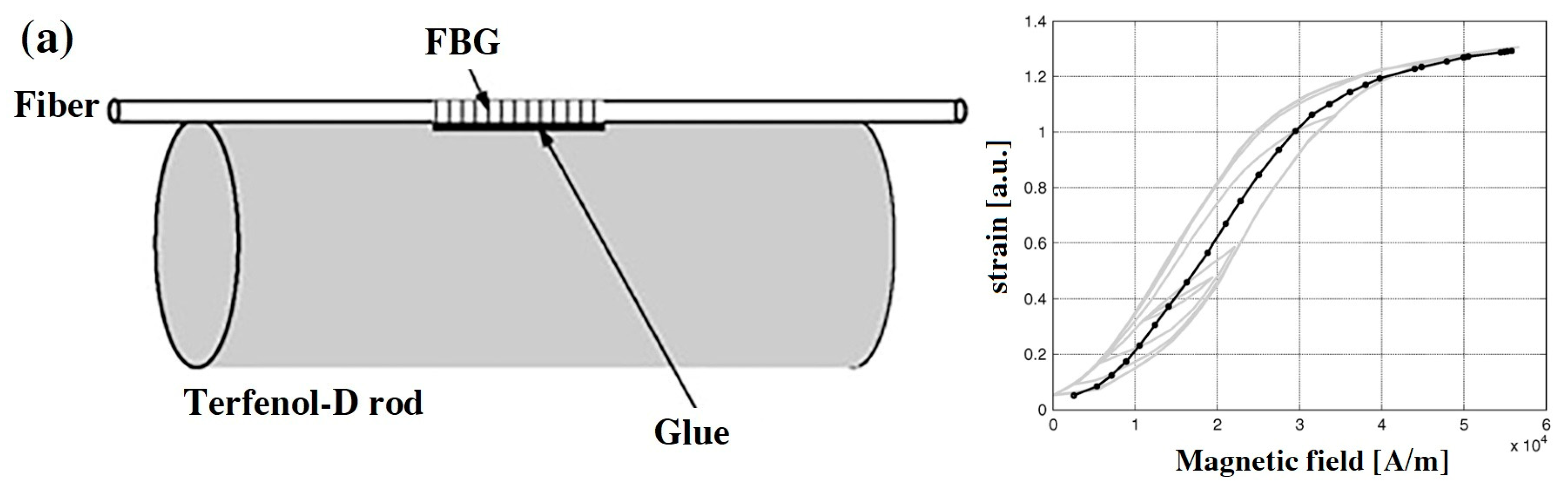
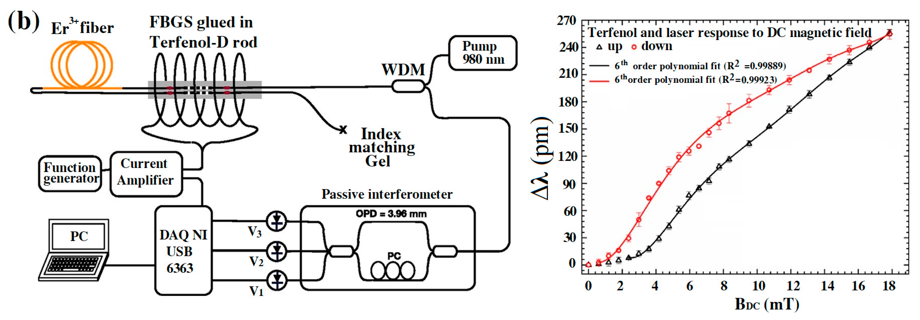
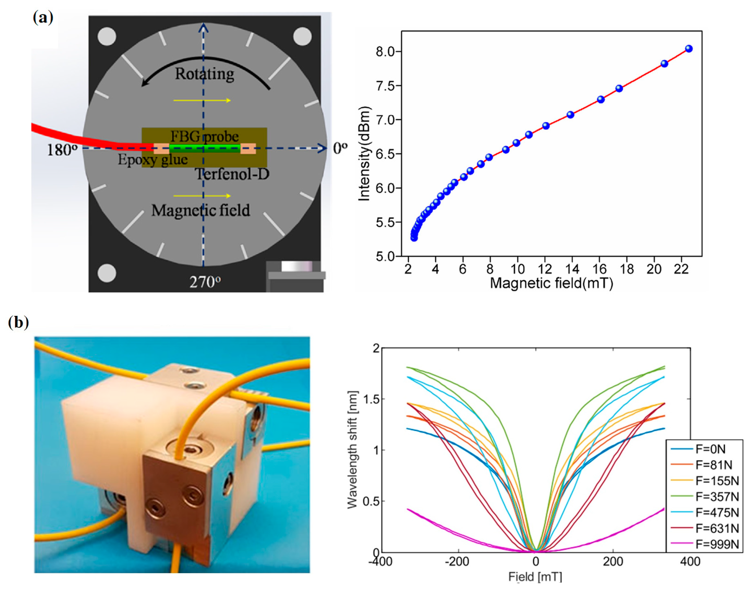
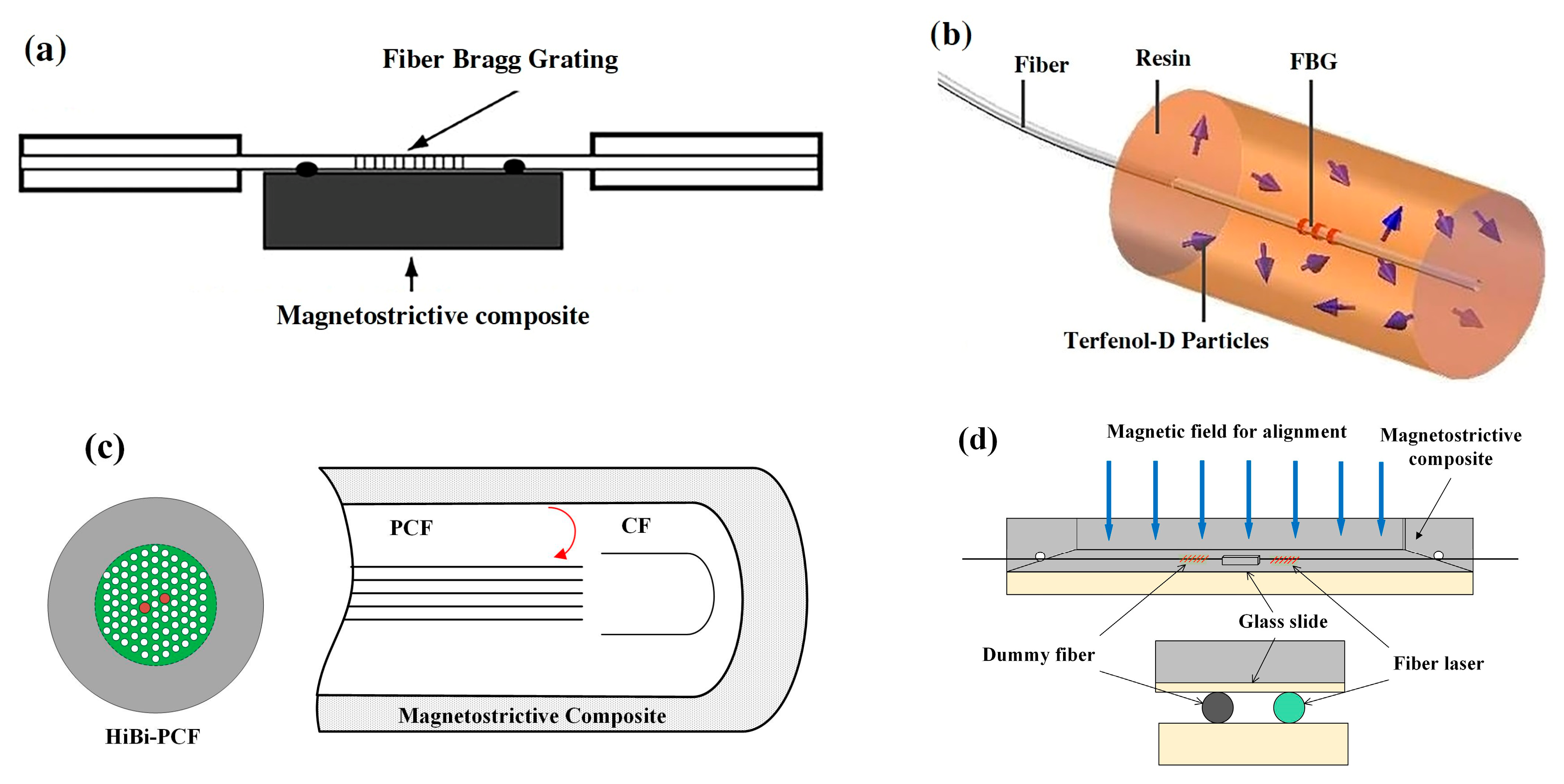
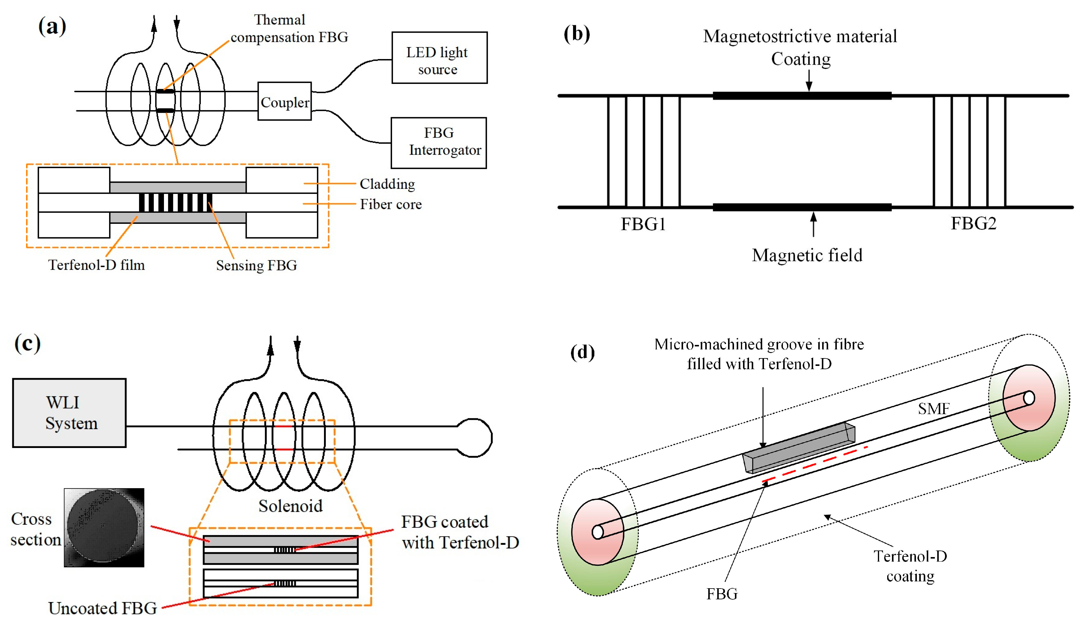
2.2. Probes Based on Magnetostriction

Magnetostriction is a unique property of ferromagnetic substance. The energy of a ferromagnetic substance comprises three parts, the exchange, anisotropy and magnetostatic energies. The three magnetic energies variation induce the variation in volume, linear length, and shape, respectively. When a ferromagnet is magnetized in a magnetic field, a deformation will be generated [25]. At the end of last century, there was a great advance in ferromagnetic materials. Giant magnetostrictive materials (GMM) were discovered, such as Terfenol-D and Galfenol, which have larger deformation in a given magnetic field [26,27,28]. Lots of sensors exploit GMM as a magnetic field transducer. The fiber Bragg gratings (FBG) are attached to GMM, and then the stress induced by the magnetic field applies on the FBG. The magnetic field can be measured by detecting the Bragg wavelength shifts.
The first type of sensors are designed by using GMM rods as the magnetic field transducer, and FBGs are bonded to the rod, which consist of a magnetic field probe. In [29], a magnetic field sensor was designed using a GMM rod and a FBG. The FBG is bonded to a Terfenol-D rod, as a sensor probe (Figure 3a). The magnetic field deforms the Terfenol-D rod, which stretches FBG to generate strain. The magnetic field can be detected by demodulating the wavelength of FBG. They also designed a compensation algorithm to achieve a linear response of this sensor. Nascimento et al. proposed a magnetic field sensor using an erbium-doped fiber optic laser and a Terfenol-D rod. A pair of FBGs are glued on the Terfenol-D rod to tune the laser wavelength (Figure 3b). The change in magnetic field can cause a laser wavelength shift. In their results, the wavelength shift is nonlinear to magnetic field intensity [30].
A compact fiber magnetic field sensor was developed based on a phase-shifted fiber Bragg grating (PS-FBG) and a Terfenol-D bar. The PS-FBG is bonded to the Terfenol-D bar by epoxy resin as the sensing probe (Figure 4a). In the presence of a magnetic field, deformation of the Terfenol-D bar induces the Bragg wavelength shift of PS-FBG. The magnetic field strength can be measured by detecting the intensity variations of the reflected spectrum [31]. Filograno et al. designed a three-axis fiber optic magnetic field sensor for magnetic resonance imaging applications (Figure 4b). The uniaxial element of sensor is a FBG fixed on a block of Terfenol-D. The tri-axial sensor consists of three mutually perpendicular uniaxial elements. They tested the performance of the sensor and studied the effect of prestress on the wavelength shift. The results demonstrate that the slope of the wavelength shift is maximum in the range from −100 mT to 100 mT when the preload is 375 N [32].
The second type of magnetic field sensors are integrated with magnetostrictive composite and FBGs. The magnetostrictive composite consists of Terfenol-D particles and an epoxy resin matrix. Liu et al. proposed a magnetic field sensor using magnetostrictive composite and FBG. The FBG is bonded to the surface of the composite, as illustrated in Figure 5a. Their results demonstrate that the peak wavelength of the sensor increases appropriately linearly with the increase of the magnetic field strength [33]. Quintero et al. presented a sensor composed of FBG and magnetostrictive composite. The FBG is coated by a thick layer of a magnetostrictive composite (Figure 5b). Terfenol-D particles are dispersed in an epoxy resin matrix. They tested the effect of volume fraction of Terfenol-D particles and particle size on sensor performance. The results show that the sensor has a resolution of 0.3 mT when the volume fraction of Terfenol-D particles (212~300 µm) is 30% [34]. They also designed a magnetic field sensor using photonic crystal fiber (PCF) coated by magnetostrictive composite (Figure 5c). The optical phase variation is a function of the change in magnetic field strength. The sensor can measure the magnetic field through detecting the wavelength shift [35]. He et al. embedded a heterodyning fiber-grating laser into magnetostrictive composite (Figure 5d). When a magnetic field is applied, the deformation stress of magnetostrictive composite acts on the heterodyning fiber laser to change the beat frequency. The response of this sensor shows a good directivity, a sensitivity of 10.5 Hz/μT, and a large measurable range up to about 0.3 T [36,37].
The third type of sensors were developed based on FBGs coated with a thin film of magnetostrictive materials. Yang et al. designed a sensor using corroded FBG coated with a layer of Terfenol-D (Figure 6a). The FBG was immersed in hydrofluoric acid solution to remove the cladding, and thin films of Terfenol-D were coated on the etched FBG through a sputtering system. They studied the effect of the etched diameter of FBG on the sensor sensitivity [38]. Chen and Li presented a magnetic field sensor based on FBG Fabry–Perot (FP) cavity ring-down technique. Two identical FBGs are written on a single mode fiber (SMF), as illustrated in Figure 6b. The section between two FBGs works as a FBG-FP cavity, which is coated by magnetostrictive material. In the presence of a magnetic field, the cavity is elongated by the magnetostriction, which causes the increase of cavity losses. The power transmission of the FBG-FP cavity is related to the magnetic field [39]. Silva et al. proposed a magnetic field sensor with thermal compensation. The sensing probe has a functional FBG coated with Terfenol-D and an uncoated FBG as a temperature compensation element, as shown in Figure 6c [40]. Schukar et al. developed a FBG sensor for magnetic field measurement. The FBG is coated by a magnetostrictive iron-nickel layer with an iron concentration of 50% [41]. A femtosecond laser-inscribed FBG sensor was proposed for detection of the magnetic field. A micro-machined groove is created in the fiber and then the grooved section is filled with Terfenol-D by RF sputter, as shown in Figure 6d [42].
Another type is distributed magnetic field sensors based on magnetostriction. Masoudi and Newson proposed a distributed optical fiber magnetic field sensor by measuring the strain on the fiber which was induced by a nickel wire bonded to the fiber. The sensing principle is based on the distributed dynamic strain measurement technique—optical time-domain reflectometry (OTDR). The fiber strain is induced by the magnetostriction of the nickel wire in the presence of a magnetic field. The phase difference between the backscattered light from the two sections of fiber is a function of the magnetic field. This sensor can detect multiple magnetic fields along a 1 km sensing fiber with a spatial resolution of 1 m [43]. Du et al. also presented a distributed magnetic field sensor based on the same principle. The magnetostrictive Fe–Co–V alloy film is attached to a 51 m-long SMF. The minimum detectable magnetic field variation is 12.9 mT, and the spatial resolution is 4 cm in the operating range from 12.9 mT to 143.3 Mt [44,45].

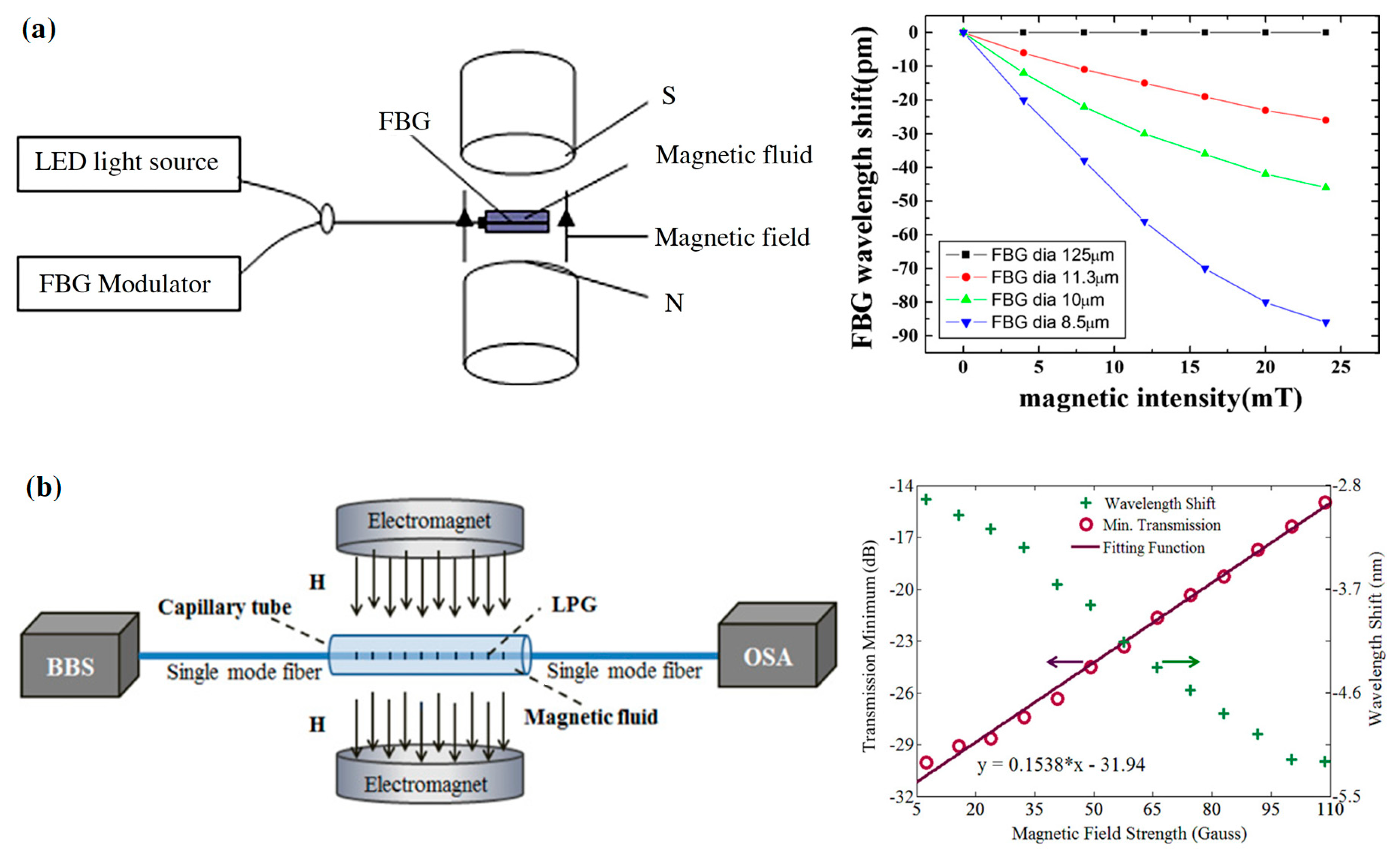
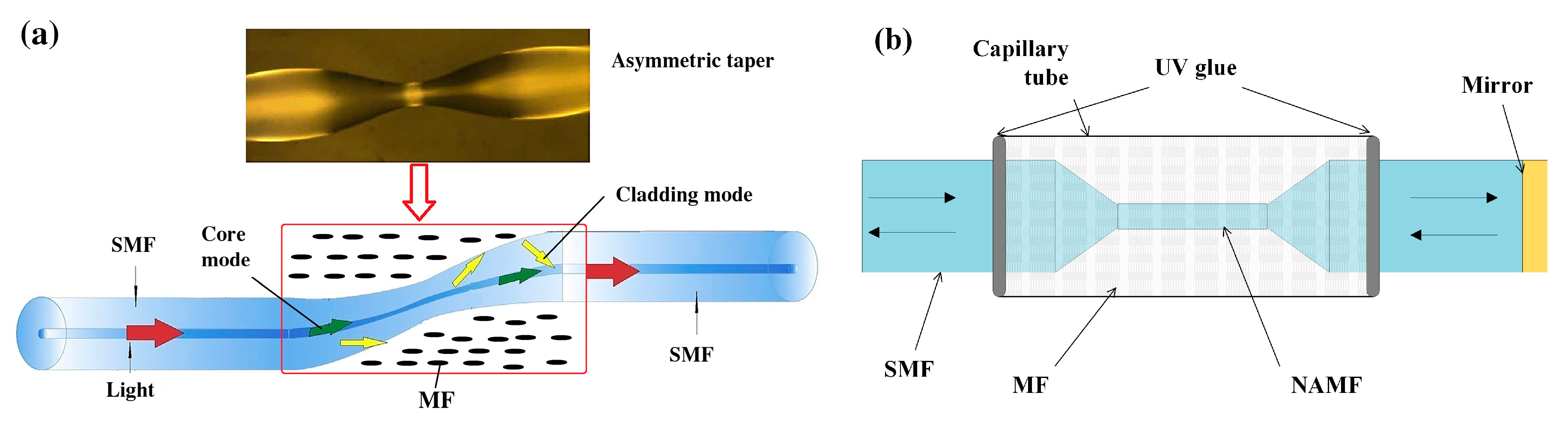
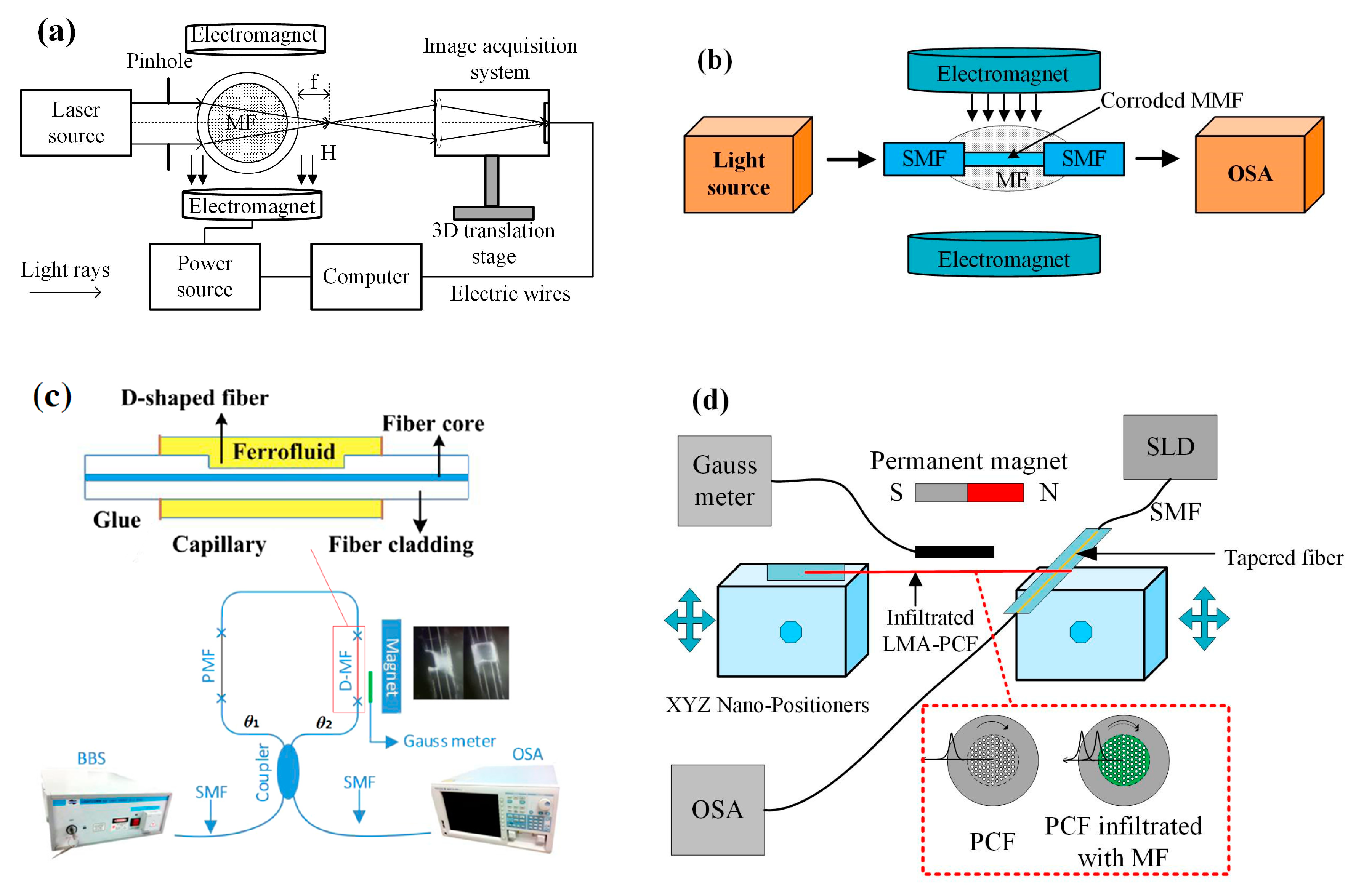
2.3. Probes Based on Refractive Index Tunability of Magnetic Fluid

Magnetic fluid (MF), commonly called ferrofluid, is a stable colloidal solution of single domain magnetic nanoparticles. The MFs have a unique combination of normal liquid behavior and the ability to interact with the magnetic field. It has many remarkable properties, such as refractive index tenability, birefringence effect, dichroism effect, thermal effect, etc. [46]. The refractive index tenability of MF has been widely used in the design of optical sensors [47,48,49].
One type of optical fiber magnetic field sensors is proposed by using MF as the cladding of optical fiber structures. For example, the MF works as the cladding of FBG. Etched FBG is placed into a container filled with MF, and the sensing system is shown in Figure 7a. The effective refractive index of FBG is related to the refractive index of cladding (i.e., MF). The refractive index of inside MF is tuned by the external magnetic field. The magnetic field can be measured by detecting the reflected wavelength shifts. They tested the interaction between the etched FBG diameter and the sensitivity of the sensor. The results demonstrate that the sensor has a sensitivity of 2.3 pm/mT and 3.44 pm/mT [50,51]. Zhang et al. placed the Long period fiber grating (LFBG) into a cavity filled with MF as a magnetic field sensor probe, as illustrated in Figure 7b. The resonance wavelength of LFBG is related to the refractive indices of the core mode and the cladding mode, wherein the core mode does not change in a magnetic field. The magnetic field can be measured through detecting the power of the transmission spectrum [52]. Gao et al. used D-shape fiber with LPBG surrounded by MF as a sensing probe for magnetic field measurement [53]. Luo et al. proposed a magnetic field sensor using a hybrid LFBG encapsulated in a capillary tube filled in MF. The hybrid LFBG is fabricated by splicing the microstructure optical fiber to SMF [54]. Zheng et al. proposed a magnetic field sensor based on the interaction between tilted fiber Bragg grating (TFBG) and MF. The TFBG and MF are packaged in a capillary tube as a sensing probe. The transmission spectrum of TFBG correlates to the magnetic field strength [55]. Narasimman et al. demonstrated a magnetic field sensor combining the etched fiber and MF composed of Co-doped ZnO nanorods. They studied the effect of ZnO nanorods of different Co concentrations on the sensor sensitivity. The results show that the sensor has a maximum sensitivity of ~18% for Co-doped ZnO nanorods in the range from 17.2 mT to 180.8 mT [56].
Another type of optical magnetic field sensor is based on MF and an optical fiber interferometer. Deng et al. developed a fiber magnetic field sensor using MF and a tapered optical fiber structure (Figure 8a). This structure works as a core-cladding-mode interferometer (CCMI). The fiber taper and MF are encapsulated in a capillary tube as the sensing probe. When the probe is immersed in the magnetic field, the wavelength of the output spectrum will shift. Their results demonstrate that this sensor has good optical properties and a high sensitivity of 162.06 pm/mT in the range from 0 to 21.4 mT [57]. They also proposed a sensor based on MF and a tapered microstructured optical fiber (TMOF) structure. The structure is a section of micro-structured optical fiber with six holes filled with MF, and the two ends are spliced to SMFs. The refractive index variation of MF induced by the magnetic field contributes to effective refractive index differences between the core and cladding modes. The magnetic field can be measured by detecting the interference spectrum shift induced by refractive index variation. The sensor has a sensitivity of 117.9 pm/mT with a linear range from 0 mT to 30 mT [58]. The optical fiber magnetic field sensors were developed using the similar sensing principle. The probe is a section of tapered thin-core fiber encapsulated in capillary tube filled with MF [59,60]. There are reported sensors based on nonadiabatic tapered optical fiber (NATOF) and MF. The nonadiabatic tapered optical fiber has a high sensitivity to the refractive index, so the sensor is more sensitive to the magnetic field. The sensor proposed by Layeghi et al. has a sensitivity of −74.4 pm/mT, and a good linearity to magnetic field strength in the range from 0 to 44 mT [61]. Luo et al. adopted a non-adiabatically tapered microfiber (NATMF) to design a sensor, which has a high sensitivity of 1744 pm/mT, as shown in Figure 8b [62].
There are magnetic field sensors proposed by combining fiber spherical structure interferometer and MF. The sensing arm consists of two special up-tapered joints on a SMF. MF is used as the cladding of the sensing arm (Figure 9a). The valley wavelength of the interference spectrum may shift as the refractive index changes. The magnetic field can be detected by monitoring the wavelength shift [63,64]. Tong et al. proposed a sensor based on another spherical structure fiber interferometer. The interferometer consists of down-taper and spherical structure, which is coated by MF identically [65]. Magnetic field sensors were developed based on a hybrid structure of SMF-no-core fiber-SMF (Figure 9b). A section of no-core fiber (NCF) is spliced between two pieces of SMFs and the structure is immersed in a capillary tube filled with MF. The coupling wavelength dip is related to the refractive index of MF dominantly. The external magnetic field generates the wavelength dip shift, and the magnetic field strength measurement can be achieved by observing the wavelength shift [66,67]. Jia et al. proposed a temperature self-compensative magnetic field sensor based on NCF cascaded with FBGs. The NCF is also sandwiched between two pieces of SMFs, which is coated with MF. The Bragg wavelengths of FBG do not change with the magnetic field, so the transmission intensity is determined by the SMF-NCF-SMF spectral shift. Due to the similar thermal effect of NCF and FBG, the cross-talk between temperature and the magnetic field is greatly reduced [68]. Pu et al. proposed a magnetic field sensor by combining the microfiber coupling structures with MF. They studied two different coupling configurations (Sagnac loop and knot resonator), and the sensing structure based on the Sagnac loop is shown in Figure 9c. The coupling area is encapsulated in a capillary tube, which is filed with MF. The sensor based on the knot resonator structure can achieve a high sensitivity of 1718 pm/mT [69]. Xia et al. adopted a FP-FBG structure to design a magnetic field sensor. Two SMFs are inserted into a capillary tube and a gap is kept between the two ends. A FBG is written on one end of SMF and the gap is filled with MF (Figure 9d). The sensor has a sensitivity of 530 pm/mT and the measurement resolution can reach 37.7 μT [70].
Ji et al. proposed a magnetic field sensor, of which the probe is based on the capillary tube filled with MF. The capillary is similar to a cylindrical lens. When a magnetic field is applied, the focal line position of the cylindrical lens changes. The magnetic field can be measured through detecting the position of the focal line (Figure 10a) [71]. Wang developed a magnetic field sensor consisting of MF and a singlemode-multimode-singlemode (SMS) fiber structure. They spliced the SMFs to a two-ends of 12-mm-long multimode fiber, and then positioned the SMS structure into a HF acid to decrease the cladding diameter. The corroded SMS fiber structure is immersed into the MF, which works as a magnetic field sensor probe (Figure 10b). The sensor has a sensitivity of −168.6 pm/mT in the range from 12 mT to 32.5 mT [72]. Lei et al. reported a magnetic field sensor based on a D-shaped fiber and MF. The D-shaped slot is created in a common SMF, and then filled with MF. The demodulation system is based on a Sagnac interferometer (Figure 10c). The sensitivity of this sensor can reach 82.3 pm/mT in the range of 0.1–30.4 mT [73]. Jiang et al. designed a magnetic field sensor by using D-shaped fiber and MF. They deposited a gold film onto the side-polished region of the fiber to realize surface plasmon resonance. The sensitivity has a significant enhancement (up to 5987 pm/mT) due the high refractive-index sensitivity of the surface plasmon resonance (SPR) [74]. Mahmood et al. demonstrated a magnetic field sensor using a PCF infiltrated with MF. A piece of PCF is infiltrated with MF as a cylindrical whispering-gallery-mode micro-resonator. In the presence of a magnetic field, the whispering-gallery-mode resonances shift to a longer wavelength. The sensing system is shown in Figure 10d. The results illustrate that the sensor sensitivity is 110 pm/mT in the range from 0 to 38.7 mT [75].
A few distributed magnetic field sensors based on MF have been covered. There are a few studies on the distributed refractive index sensing [76]. Du et al. detected the refractive index of the external medium surrounding the fiber by analyzing the Rayleigh backscattering signals, wherein the OFDR technique is adopted. This concept can be used as a reference for the distributed measurement of the magnetic field based on MF.

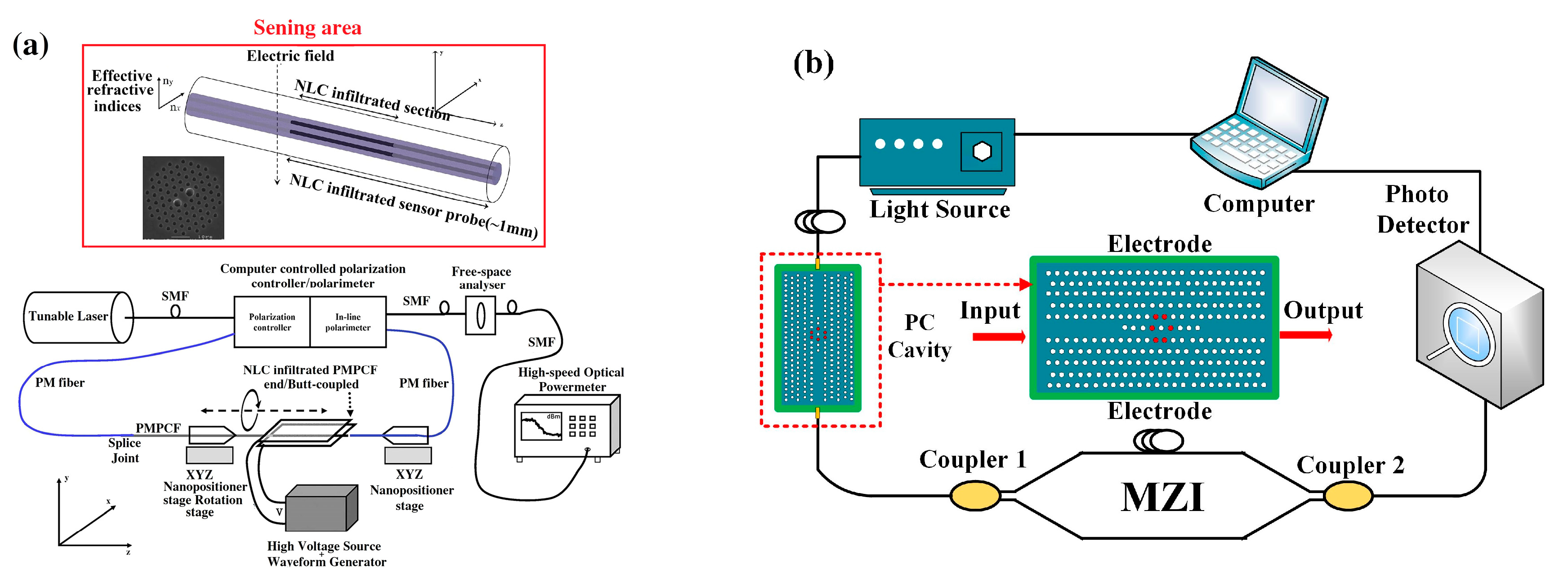
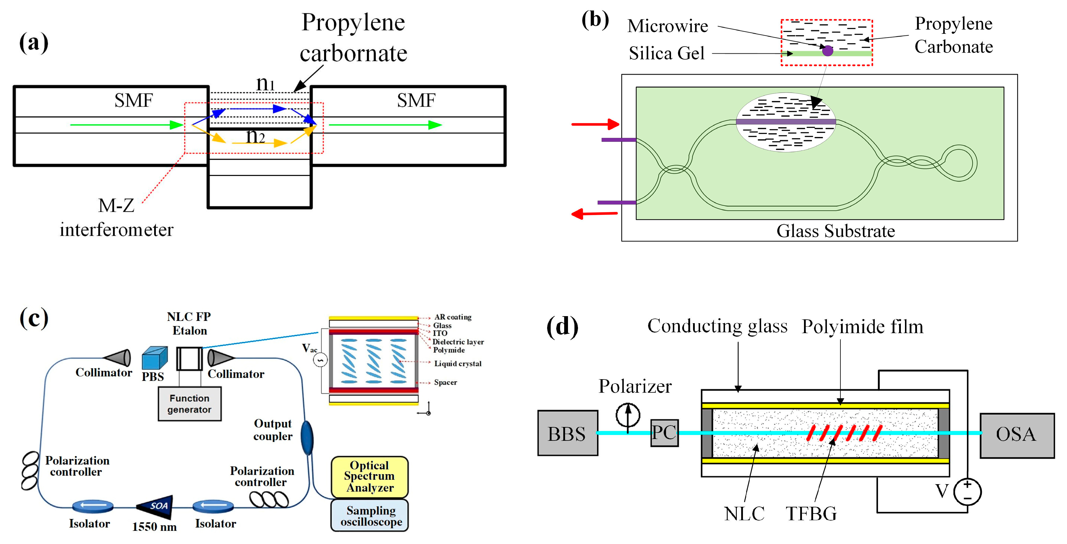
3. Electric field Optical Sensors

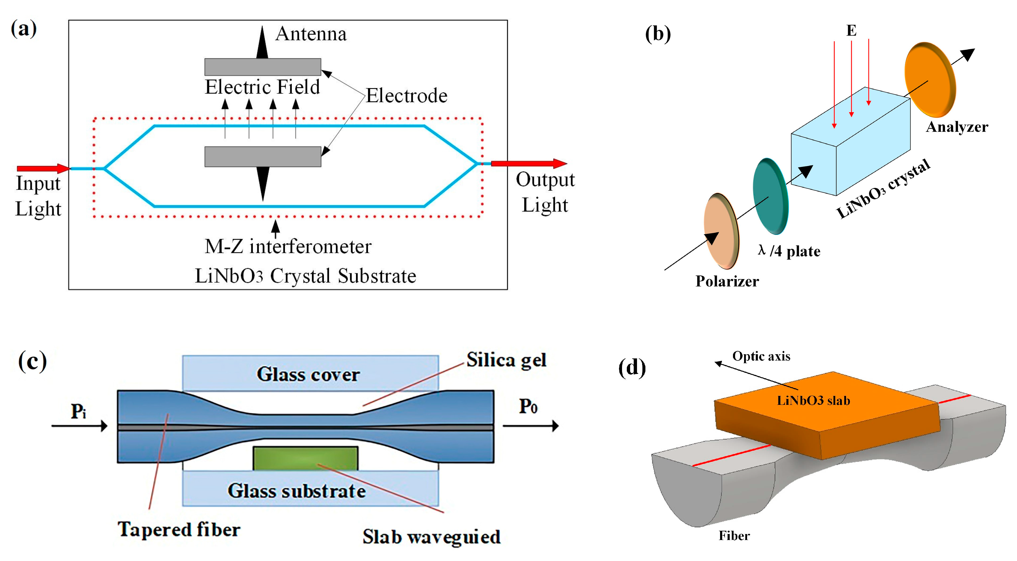
3.1. Probes Based on the Electro-Optic Effect of Crystal

An electro-optic effect is a change in optical properties of a substance in response to an electric field. These property changes can be classified into two types: variation in absorption and refractive index. The application of electro-optic crystals in electric field measurement has drawn attention over recent years [77,78,79].
One type of optical electric field sensor is developed using electro-optic crystal as a waveguide to sense an electric field. The refractive index of crystal is changed in the presence of an electric field. Zeng et al. used LiNbO3 crystals to design an integrated electro-optic sensor for electric field measurement. The sensor area is a Mach-Zehnder interferometer (MZI), as shown in Figure 11a. Two parts of light interfere with each other by passing through the right coupling. Electrodes with an antenna are around one arm of the interferometer. When an electric field is applied to the antenna, a voltage is induced across the electrodes of the modulator. Then the change in refractive index of LiNbO3 crystal causes the change in phase of transmission light. The power of the sensor output signal is proportional to the applied electric field strength. They analyzed the performance of sensors with different electrodes. The results show that the mono-shield electrode sensor without an antenna is more efficient than those with antennas in measurable amplitudes [80,81,82]. Toney et al. designed an integrated optical electric field sensor by using a LiNbO3 crystal waveguide and a Mach–Zehnder interferometer. This sensor can achieve a minimum detectable field of 20 mV/m/√Hz at 100 MHz in the electric fields from 20 mV/m to 30 kV/m [83]. Yang et al. proposed an optical electric field sensor using a LiNbO3 crystal. The sensing unit is shown in Figure 11b. The phase shift of light transmitted in the crystal changes in an applied electric field. The sensor output is linear to the electric field strength in the range from −801 kV to 801 kV with a wide frequency band (10 Hz–10 MHz) [84].
Han et al. proposed an all-fiber electric field sensor based on tapered fiber and a LiNbO3 slab waveguide coupler (Figure 11c). The evanescent is coupled between a tapered fiber and a slab waveguide. The shift of the resonance wavelength is related to electric field intensity. The minimal resolution of this sensor is approximately 15 kV/m [85]. Seng et al demonstrated an electric field sensor based on a slab of LiNbO3 and D-shaped fiber. The D-fiber is etched to be a taper, and the slab is positioned closed to the tapered core, as shown in Figure 11d. Light couples between the D-fiber and the slab waveguide to generate a resonance wavelength. The change in the refractive index induced by the electric field causes the resonance wavelength shift. The electric field strength can be measured by detecting the wavelength shift [86,87,88,89]. Chadderdon et al. presented an electric field sensor using a coupling configuration between D-fiber and a waveguide slab. They chose an electro-optic polymer as the waveguide slab because the materials have the lowest RF permittivity and strong electro-optic effect. The sensor has a sensitivity of 0.147 pm/ kV [90].
Togo et al. designed an electric field sensor, which consists of an electro-optic crystal (CdTe), a Faraday rotator, a collimating lens, a ferrule, and a piece of PMF, as shown in Figure 12a. Polarized light is transmitted to the CdTe crystal through PMF and reflected by the dielectric mirror. When an electric field is applied to the CdTe crystal, birefringence is induced and the polarization of light changes. The polarization change is proportional to the electric field intensity. The performance tests show that the response of the sensor is stable with a fluctuation of less than 0.3 dB [91]. Gaeremynck et al. proposed an electro-optic sensor based on a ZnTe crystal, which can measure two orthogonal components of the electric field simultaneously (Figure 12b). The sensing area consists of a ZnTe crystal and a laser probe beam. An elliptically polarized light is split into two beams, and the polarization states of the two beams of light are characterized by the refractive index. In the presence of an electric field, the change in the refractive index of ZnTe crystal will induce the variation of phase [92]. Barbieri et al. used a Barium-Borate (BBO) crystal as a part of the electric field sensing unit. The birefringence of BBO crystal is proportional to the electric field strength. This sensor can measure two components of the electric field by a single anisotropic crystal [93].
The other type of electro-optic electric field sensor is proposed using the liquid crystal (LC) as the electric field sensing element. Mathews et al. developed an electric field sensor using a polarization-maintaining photonic crystal fiber (PMPCF) infiltrated nematic liquid crystal (NLC), as shown in Figure 13a. They studied the transmission properties for different lengths of the infiltrated section of PCF. The results demonstrate that the sensor has a sensitivity of 50 V/m in the range of 3.4–4.1 MV/m [94,95,96]. Zhao et al. developed an electric field sensor using a photonic crystal cavity infiltrated with LC (Figure 13b). An electric field applied can induce the resonance wavelength of a photonic crystal cavity shift. This wavelength shift is monitored by a MZI. Their results illustrate that the sensor can achieve a high sensitivity of 7 nW/(V/m) and a maximum resolution of 0.143 V/m [97].
Zhu et al. designed a compact electric field sensor using an optical fiber interferometer. A short section of SMF is spliced between two sections of SMF with a large lateral offset of 62.5 μm, which can work as a MZI, as shown in Figure 14a. The open arm of the interferometer is filled with propylene carbonate. In the presence of an electric field, the refractive index of propylene carbonate will change, which causes interferometric fringe shifts. The electrical field can be acquired by monitoring the fringe shift [98]. Han et al. also presented an electric field sensor based on propylene carbonate and MZI (Figure 14b). The interferometer is composed of silica micro-wire. One arm of the interferometer is coated by propylene carbonate. The sensor can detect an electric field with a frequency of 50 Hz and an impulse electric field. The sensor can detect a minimum strength of 59 V/m for a 50 Hz electric field [99].
Fiber-optic electric field sensors were proposed using a NLC FP etalon-based multiwavelength-swept laser. The NLC FP etalon can be looked at as a wavelength filter by applying the electric field (Figure 14c). The transmission wavelengths change according to the electric field applied to the NLC FP etalon [100,101,102]. Tabassum et al. presented a sensitivity-enhanced electric field sensor based on the SPR. The sensing area is a section of corroded optical fiber immersed in a liquid dielectric medium, and the corroded region is coated by metal film. They analyzed the effect of coating metal materials on the performance of the sensor. The result illustrates that the sensor with bimetallic layers is better than the single metal layer ones [103]. Chen et al. proposed an electric field sensor based on TFBG immersed in liquid crystal. They embedded a TFBG into a NLC cell as a sensing probe (Figure 14d). In an electric field applied, NLC orientation change will cause the variation of its refractive index. The surrounding refractive index can be sensed by the TFBG. Their results demonstrate that the sensor can measure an electric field over a range of 100–480 kV/m with a sensitivity of 0.287 dB/kV/cm [104].

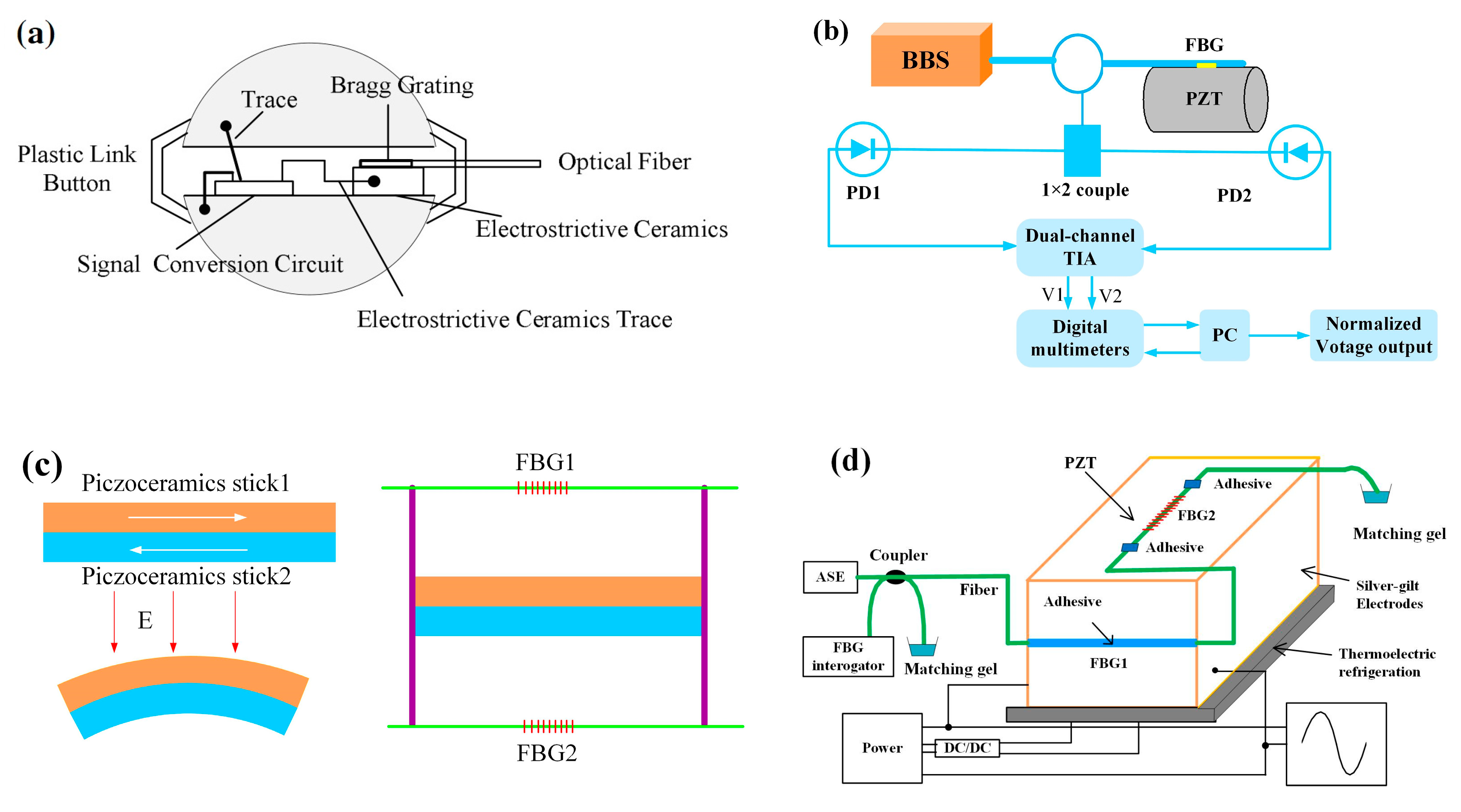
3.2. Probes Based on the Converse Piezoelectric Effect

The piezoelectric effect is a unique property of materials where they will generate an electric field or current if subjected to physical stress. Commonly, piezoelectric materials include piezoelectric ceramic (PZT) and polyvinylidene fluoride (PVDF). The same effect can also be observed in reverse, where an imposed electric field on the crystal will put stress on its structure, which is the converse piezoelectric effect. The converse piezoelectric effect has been widely used for the design of electric field sensors.
Marignetti et al. developed a FBG sensor to detect the electric field for the end windings of high-voltage electric machines. The working principle relies on the electrostrictive effect of silica. When an electric field is applied, a mechanical force generates a strain resulting in a wavelength shift of FBG. The field strength can be measured by demodulating the wavelength shift [105]. Zhao et al. presented an alternating current (AC) electric field sensor based on electrostrictive ceramics and FBG. The sensor head is composed of FBG attached to ceramics, two metal spherical shells, and a signal conversion circuit (Figure 15a). When an electric field acting on the metal spherical, the metal spherical shell induces an electric signal, and the signals are transformed and amplified. Then the transformed DC voltage signals apply on the ceramics and the stress induces a wavelength shift of FBG. Electric field strength can be measured through the detection of a wavelength shift [106]. Anirudh et al. proposed a FBG sensor for DC electric fields measurement. The electric field transducer is a PZT crystal, and the FBG is boned to PZT crystal. In presence of an electric field, PZT crystal deformation induces the wavelength shift of FBG. They also designed a wavelength interrogation system, as shown in Figure 15b [107].
Liu et al. demonstrated a FBG electric field sensor with two of the same piezoceramics blocks glued together with opposite directions. Two rods are fixed on the two ends of piezoceramics blocks respectively, and two FBGs are glued to the rods (Figure 15c). When an electric field is applied to the piezoceramics, the two piezoceramics blocks will deform inversely and bend to the same side, which induces the wavelength shift of two FBGs [108]. Yao et al. developed an electric field sensor based on two FBGs adhered to a piezoelectric ceramic block (Figure 15d). FBG1 is glued on the surface of the piezoceramics along the d33 polarized direction, and FBG2 is glued along the d31 polarized direction. The difference of the Bragg wavelength of FBG1 and FBG2 is regarded as the output, which can enhance the sensor sensitivity and reduce the cross-talk of temperature [109]. Floridia et al. used a similar method to propose a temperature-independent FBG sensor for electrical field measurement. The sensing probe is a FBG bonded to piezoelectric substrate, and another FBG is attached to an identical piezoelectric substrate as temperature compensation [110].

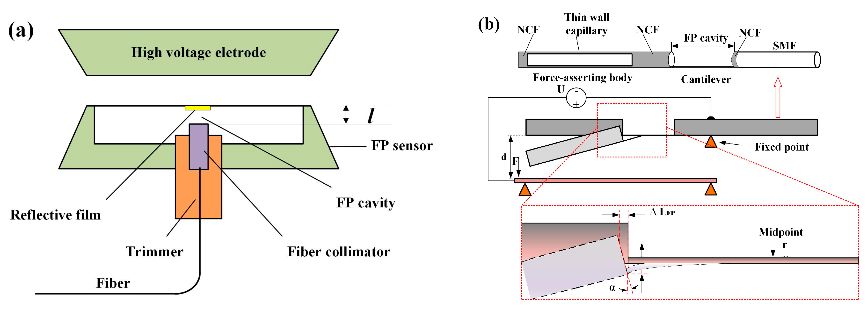
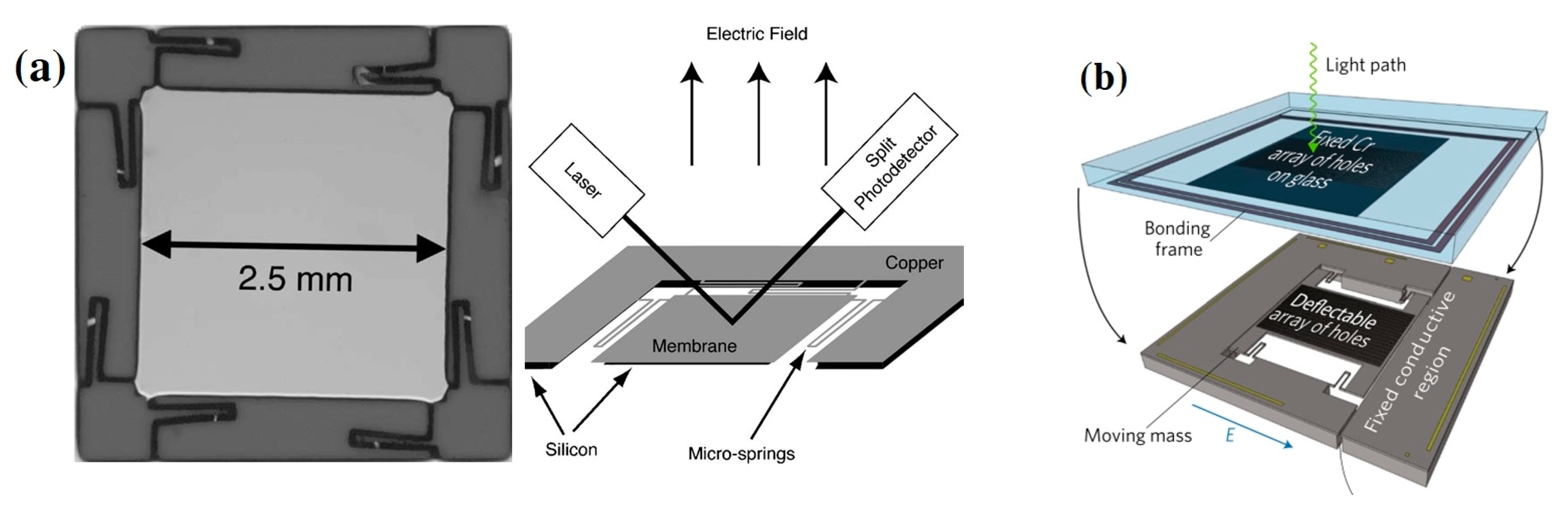
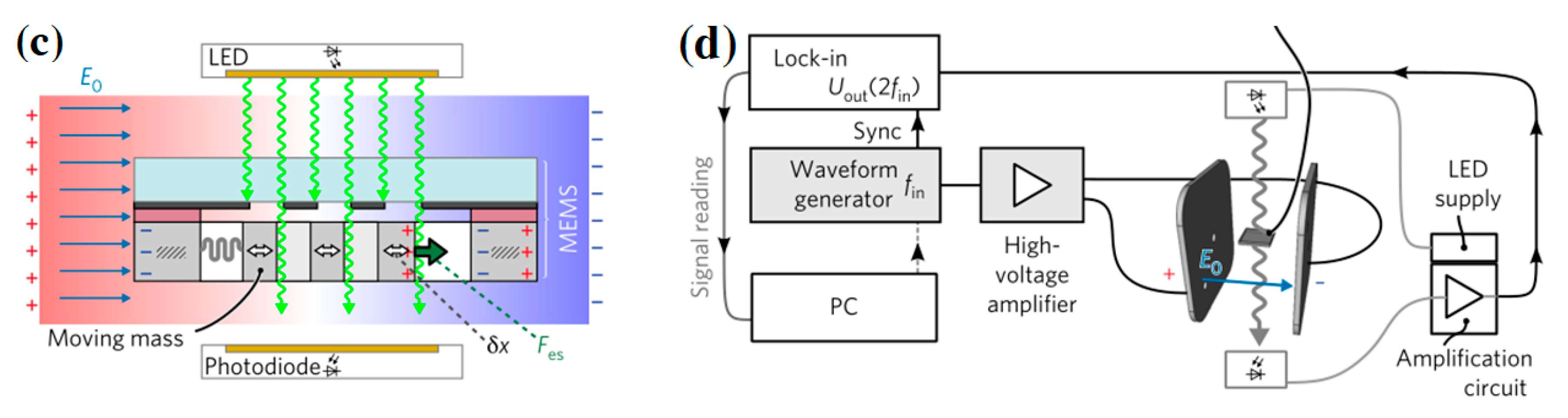
3.3. Probes Based on Electrostatic Attraction

A conductor is placed in an electric field, the free charge carriers inside the conductor redistribute, in contrast with the lattice-bound opposite charges. Two surfaces with opposite charges will generate an attractive electric force. Zhang et al. designed a high voltage electrostatic sensor based on the Fabry–Perot interferometer (FPI) (Figure 16a). The FP cavity of the sensor is formed by an optical collimator and polyester film aluminized outside. When a high voltage is applied on the electrode, an electric field will be generated. The polyester film is deformed by an electrostatic force, which causes the change in length of the F-P cavity and the output spectrum shift of the sensor [111]. Javernik and Donlagic proposed a fiber-optic voltage sensor based on the principle of electric charge attraction. The sensor head consists of a SMF fiber, a section of NCF, a micro-cantilever, and a force-asserting body, as illustrated in Figure 16b. The force-asserting body is coated by conductive transparent material. When the sensor is connected to the voltage/potential, an attractive electric force will deflect the micro-cantilever. The deflection causes the change in length of the F-P cavity and induces the F-P peak wavelength shift. They claimed that this sensor could be used for DC and AC power-grid frequency voltage measurements [112].
Roncin et al. developed an electric field sensor using a micro-spring supported copper membrane (Figure 17a). The sensing principle is based on the electrostatic force to deflect the copper membrane and an optical sensor to detect the membrane movement. Their result shows that the sensor can detect a minimum AC field of 0.3 V/m at 97 Hz when a 17 kV/m DC bias field is applied [113]. Andreas Kainz et al. developed an optical microelectromechanical system (MEMS) sensor for electric field measurement. The sensor structure is a silicon microstructure, as shown in Figure 17b. The sensor configuration is composed of a fixed layer and a movable layer. The fixed layer is a glass plate with Cr film, which works as an optical shutter. The movable layer is a spring-suspended Si plate, and the moving mass part could be displaced by the electrostatic force when an electric field is applied. A beam of light passes through the fixed layer and the moving layer successively, and then is detected by a photodiode. The displacement of the moving mass part can be read out by detecting the light flux. The electric field strength is related to the output of photodiode. The sensor has an electric field resolution of 100 V/m/√Hz with a measurement range of tens of kilovolts per meter [114].

4. Conclusions and Outlook

In this review, a variety of sensing configurations of electromagnetic field sensors were demonstrated. The performance parameters of these sensors are shown in Table A1 and Table A2 in the Appendix A. Magnetic field sensors were summarized into three types according to the sensing methodology of sensor probes. Wherein, the probes based on the Faraday effect originates earliest, and have a complex sensing system, including lots of optical elements, such as the Faraday rotator, polarizer, PMF, etc. The sensor sensitivity is determined by the Verdet constant. The Verdet constant of common silica fiber is very small, which makes it not suitable for weak magnetic field strength. The detection variable is the rotation angle of polarization light, it has strong resistance to interference, and can work in unshielded environments. Because the Verdet constant is almost the only limitation to the sensitivity, the sensitivity can be enhanced easily through selecting the magneto-optic materials with large Verdet constant. Therefore, it can achieve a large detecting range for magnetic field.
The sensing method based on magnetostriction developed with the rising of giant magnetostrictive materials. The sensor element has merits of easy fabrication, compact size and strong environment adaptability. The magneto-elastic materials have intrinsic hysteresis phenomena, meaning these sensors cannot monitor the field with high frequency. The deformation of GMM is relatively small under a small applied magnetic field, and the deformation has a definite linear range. This sensing scheme is suitable for the measurement of stationary and large magnetic fields (<500 mT).
The sensing principle based on refractive index tunability of magnetic fluids has become a hotspot for magnetic field measurement in recent years, because of its high sensitivity, compact size, and flexibility in combination with various optical fiber structures, such as etched fiber gratings (FBG, LFBG, TFBG), fiber taper, F-P cavity, and other fiber structures. However, the detecting range is limited by the tunable range of the refractive index of magnetic fluid. The operating range of this type of sensor is relatively small (<100 mT). There is cross-talk between temperature and the magnetic field, so the thermal compensation should be taken into consideration in real applications.
The electric field sensors are classified into three types according to the sensing principles. The principle, based on the electric-optic effect of crystal, is the mainstream sensing scheme due to the good electro-optic properties of the crystal. These sensors usually have integrated probes, which is a combination of electro-optic crystals with fiber interferometric structures. The interferometric structure-based probe is highly sensitive to the electric field, but susceptible to external interference. The sensing method based on piezoelectric ceramics has a simple structure and easy fabrication, but it has low sensitivity due to small deformation in the presence of a weak electric field. The sensing principle based on electrostatic attraction is a less commonly-used sensing method, but this is a promising alternative to optical MEMS sensors for electric field measurement.
Most of the above-discussed sensors are single point measurement, seldom involving distributed measurement. Further work can focus on the distributed measurement because of the intrinsic advantages of optic fiber sensing technology. Fully distributed electric or magnetic field measurement could have a huge impact on many applications, such as the power industry. Currently, there are no reported optical sensors on the simultaneous sensing of electric and magnetic fields. In the future, the optical sensors for simultaneous measurement of electromagnetic fields can be taken in consideration, because both fields exist simultaneously sometimes.

Author Contributions

All authors worked in the design, literature search, and writing of the manuscript.

Funding

This work is supported by Open Fund of State Key Laboratory of Power Grid Environmental Protection (No. GYW51201801172) and the Xi’an Jiaotong University Funding (No. PY3A048).

Conflicts of Interest

The authors declare no conflict of interest.

Appendix A

Aimed to give a clear performance comparison, this appendix demonstrates a table of the main sensing parameters of the above-discussed sensors.
Table A1. Performance parameters of optical fiber magnetic field sensors.
Detection MechanismSensor Probe ConfigurationField TransducerProbe Size/mmDetecting RangeSensitivity/ResolutionRef
Transmission intensityTb Fiber-PZFTb Fiber20 long0.02–3.2 T0.49 rad/T[15]
Beat frequency shiftDBRFiber grating 20 long32.5 kHz/mT[19]
Frequency responseQWP-MO-mirrorMO polymer15 long20 fT/√Hz[22]
State of polarizationSilica FiberSilica Fiber0–1.5 T100 mT[23]
Wavelength shiftTerfenol-D-FBGTerfenol-DΦ 4.7 × 20[29]
Wavelength shiftTerfenol-D-FBGTerfenol-DΦ 5 × 100–16.47 mT4.88 mT[30]
Wavelength shiftTerfenol-D-PS-FBGTerfenol-D20 × 3 × 32.43–22.54 mT0.023 mT[31]
Wavelength shiftTerfenol-D-FBGTerfenol-D60 × 60 × 600–350 mT[32]
Wavelength shiftTerfenol-D composite-FBGTerfenol-D composite25 × 4 × 40–183 mT3.71 pm/mT[33]
Wavelength shiftTerfenol-D composite-FBGTerfenol-D compositeΦ 1.5 × 70–750 mT3.3 pm/mT[34]
Wavelength shiftTerfenol-D composite-FBGTerfenol-D composite50 long0–300 mT6 pm/mT[35]
Beat frequency shiftTerfenol-D composite-HiBi-PCFTerfenol-D composite50 × 10 × 100–300 mT10.5 kHz/mT[36]
Wavelength shiftTerfenol-D film- FBGTerfenol-D filmsΦ 0.085 × 150–50 mT0.9 pm/mT[38]
Ring-down time spectroscopyTerfenol-D film-FBG-FPITerfenol-D filmΦ 0.125 × 5000–28.8 mT0.485 ns/mT[39]
Wavelength shiftTerfenol-D film-FBGTerfenol-D film1.6 um20–100 mT0.4 mT[40]
Wavelength shiftIron-nickel-FBGIron-nickel Φ 0.185 × 220–6 mT0.75 mT[41]
Wavelength shiftTerfenol-D-FBGTerfenol-D 30 long0–20 mT0.3 pm/mT[42]
RBS spectral shiftFeCoV film-fiberFeCoV films0–143.3 mT5.3 mT[45]
Wavelength shiftFBG-MFMF(Fe3O4)0–25 mT3.44 pm/mT[51]
Transmission spectrum intensityLFBG-MFMF(EMG605)Φ 0.45 × 300–11 mT1.54 dB/mT[52]
Resonance wavelength shiftLPFGMF(EMG605)Φ 1 × 1000–189.7 mT176.4 pm/mT[53]
Resonance wavelength shiftMOF-LFBG-MFMF(Fe3O4)Φ 0.5 × 1000–72.5 mT−520 pm/mT[54]
Extinction ratioTFBGMF(EMG605)0–19.6 mT[55]
Transmission spectrum intensityEtched fiber-MFMF(Co-ZnO nanorods)Φ 1 × 42017–180 mT[56]
Wavelength shiftTMOF-MFMF (Fe3O4)0–30 mT117.9 pm/mT[58]
Wavelength shiftCCMI-MFMF (Fe3O4)Φ 0.3 × 1000–21.4 mT162.06 pm/mT[57]
Transmission spectrum intensityTTCF-MFMFΦ 1 × 804–16 mT−1.039 dB/mT[59]
Wavelength shiftMMI-MFMF (EMG607)Φ 1 × 300–22 mT−2.93 nm/mT[60]
Wavelength shiftNATOF-MFMF (Fe3O4)0–44 mT−71.7 pm/mT[61]
Wavelength shiftNATMF-MFMF10–22.5 mT1744 pm/mT[62]
Transmission spectrum intensityUp-tapered joints-MFMF (Fe3O4)2–30 mT−0.2121 dB/mT[63]
Transmission spectrum intensityIMI-MFMF (EMG605)0–12 mT0.106 dB/mT[65]
Wavelength shiftSNS fiber-MFMF(EXP08103)35 long0–6 mT6.33 nm/mT[67]
Wavelength shiftMFC-MFMF0–240 mT1718 pm/mT[69]
Wavelength shiftFPI-FBG-MFMF (EMG605)20–60 mT0.53 nm/mT[70]
Focal line positionTube filed with MFMF--[71]
Wavelength shiftSMS fiber-MFMF (Fe3O4)12–32.5 mT−168.6 pm/mT[72]
Wavelength shiftD-shaped fiber-MFMF (APGS12n)0.1–30.4 mT82.3 pm/mT[73]
Wavelength shiftD-shaped fiber with gold film-MFMF (EMG 605)0–22.5 mT5987 pm/mT[74]
Wavelength shiftPCF-MFMF0–38.7 mT110 pm/mT[75]
Table A2. Performance parameters of optical fiber electric field sensors.
Detected VariableSensor Probe ConfigurationField TransducerProbe Size/mmDetecting RangeSensitivity/ResolutionRef
Output light intensityMZI-LiNbO3LiNbO3 55 × 2 × 10–250 kV/m2 mV/(kV/m)[80]
Output light intensityMZI-LiNbO3LiNbO3 50 × 10 × 90.02–30 kV/m20 mV/m/√Hz[83]
Output light intensitySMF-LiNbO3LiNbO365 × 15 × 15±801 kV/m[84]
Resonance wavelength shiftTapered fiber-LiNbO3 LiNbO3 <13.16 MV/m15 kV/m[85]
Resonance wavelength shiftD-shaped fiber-LiNbO3 LiNbO33900 × 27 × 20<18 MV/m50 pm/(MV/m)[85]
Output light intensityCdTe crystal-Faraday rotatorCdTe[91]
Output light intensity ZnTe-Bragg mirrorZnTe[92]
Output light intensityPMPCF-NLCNLC30 long3.4–4.1 MV/m50 V/m[94]
Output light intensityPC cavity-LCLC2–10 MV/m0.143 V/m[97]
Transmission spectrum intensityMZI-Propylene carbonatePropylene carbonate5–15 MV/m∼0.1 W/(V/m)[98]
Output light intensityMZI-Propylene carbonatePropylene carbonate<1400 kV/m∼89 V/m[99]
Wavelength shiftFP etalon-NLCNLC4.494–7.865 kV/m121 V/m[100]
Transmission spectrum intensityTFBG-NLCNLC100~400 kV/m2.87 dB/(MV/m)[104]
Wavelength shiftFBG-PLZTPLZT0–200 kV/m-[106]
Wavelength shiftFBG-PZTPZT0–400 V/mm0.45 pm/(kV/m)[107]
Wavelength shiftFBG-PZTPZT±30 kV/m−27 nW/V[108]
Resonance wavelength shiftFPI-polyester film polyester film500–1600 kV/m[111]
Membrane movement.Membrane-photodetectorCoper membrane0–17 kV/m3 3 μV /(V/m)[113]
Light flux intensityMEMS chipSi plate6 × 6<10 kV/m100 V/m/√Hz [114]

Appendix B

This appendix contains the acronyms list used in this manuscript.
AcronymDefinition
ACAlternating Current
BBOBarium-Borate
CCMICore–Cladding–Mode Interferometer
CdTeElectro-Optic Crystal
DBRDistributed Bragg Reflector
DCDirect Current
DGDDifferential Group Delay
EMFElectromagnetic Field
FBGFiber Bragg Grating
FPFabry-Perot
GMMGiant Magnetostrictive Material
HFHydrofluoric
HiBi PCFHighly Birefringent Photonic Crystal Fiber
IMIIntermodal Interferometer
LCLiquid crystal
LFBGLong-period Fiber Grating
MEMSMicro Electro Mechanical Systems
MFMagnetic Fluid
MFCMicrofiber Coupler
MMIMicrofiber Mode Interferometer
MOFMicrostructured Optical Fiber
MZIMach-Zehnder Interferometer
NATMFNonadiabatic Tapered Microfiber
NATOFNonadiabatic Tapered Optical Fiber
NCFNo-Core Fiber
NLCNematic Liquid Crystal
OFDROptical Frequency Domain Reflectometer
OTDROptical Time-Domain Reflectometry
PCFPhotonic Crystal Fiber
PDLPolarization Dependent Loss
PLZTLead lanthanum zirconate titanate
PMFPolarization Maintaining Fiber
PS-FBGPhase-Shifted Fiber Bragg Grating
PVDFPolyvinylidene Fluoride
PZFPolarization Fiber
PZTPiezoelectric ceramics
RBSRayleigh Backscattering Spectra
SMFSingle-Mode Fiber
SMSSinglemode–Multimode–Singlemode
SNSSinglemode-No-core-Singlemode
TbTerbium
TFBGTilted Fiber Bragg Grating
TMOFTapered Microstructured Optical Fiber
TTCFTapered thin-core fiber

References

  1. Sipilä, P.; Lange, D.; Lechner, S.; Low, W.; Gross, P.; Baller, M.; Wachutka, G.; Wiesinger, F. Robust, susceptibility-matched NMR probes for compensation of magnetic field imperfections in magnetic resonance imaging (MRI). Sens. Actuators A Phys. 2008, 145, 139–146. [Google Scholar] [CrossRef]
  2. Thiel, F.; Kosch, O.; Seifert, F. Ultra-Wideband Sensors for Improved Magnetic Resonance Imaging, Cardiovascular Monitoring and Tumour Diagnostics. Sensors 2010, 10, 10778–10802. [Google Scholar] [CrossRef] [PubMed] [Green Version]
  3. Hand, J.; Bosmans, H.; Caruana, C.; Keevil, S.; Norris, D.; Padovani, R.; Speck, O. The European Federation of Organisations for Medical Physics Policy Statement No 14: The role of the Medical Physicist in the management of safety within the magnetic resonance imaging environment: EFOMP recommendations. Phys. Med. 2013, 29, 122–125. [Google Scholar] [CrossRef] [PubMed] [Green Version]
  4. Ferdinand, P.; Denayrolles, Y.; Mersier, C.; Plantey, J.; Recrosio, N.; Pays, M.; Vielpeau, D. The potential for distributed sensors and optical fibre sensor networks in the electric power industry. Meas. Sci. Technol. 1990, 1, 908–916. [Google Scholar] [CrossRef]
  5. Yin, W.; Karimian, N.; Liu, J.; Hao, X.; Zhou, L.; Peyton, A.; Strangwood, M.; Davis, C. Measurement of electromagnetic properties of power station steels. NDT E Int. 2012, 51, 135–141. [Google Scholar] [CrossRef]
  6. Popovic, D.R.; Dimitrijevic, S.; Blagojevic, M.; Kejik, P.; Schurig, E.; Popovic, R.S. Three-Axis Teslameter With Integrated Hall Probe. IEEE Trans. Instrum. Meas. 2007, 56, 1396–1402. [Google Scholar] [CrossRef]
  7. Renella, D.P.; Dimitrijevic, S.; Spasic, S.; Popovic, R.S. High-accuracy teslameter with thin high-resolution three-axis Hall probe. Measurement 2017, 98, 407–413. [Google Scholar] [CrossRef]
  8. Bienkowski, P.; Trzaska, H. Electromagnetic Measurements in the Near Field; SciTech Publishing, Inc.: Raleigh, NC, USA, 2012. [Google Scholar]
  9. Cui, Y.; Yuan, H.; Song, X.; Zhao, L.; Liu, Y.; Lin, L. Model, Design, and Testing of Field Mill Sensors for Measuring Electric Fields Under High-Voltage Direct-Current Power Lines. IEEE Trans. Ind. Electron. 2018, 65, 608–615. [Google Scholar] [CrossRef]
  10. Bohnert, K.; Gabus, P.; Kostovic, J.; Brandle, H. Optical fiber sensors for the electric power industry. Opt. Lasers Eng. 2005, 43, 511–526. [Google Scholar] [CrossRef]
  11. Passaro, V.; Dell’Olio, F.; De Leonardis, F. Electromagnetic field photonic sensors. Prog. Quantum Electron. 2006, 30, 45–73. [Google Scholar] [CrossRef]
  12. Zeng, R.; Wang, B.; Niu, B.; Yu, Z. Development and Application of Integrated Optical Sensors for Intense E-Field Measurement. Sensors 2012, 12, 11406–11434. [Google Scholar] [CrossRef] [PubMed] [Green Version]
  13. Alberto, N.; Domingues, M.F.; Marques, C.; André, P.; Antunes, P. Optical Fiber Magnetic Field Sensors Based on Magnetic Fluid: A Review. Sensors 2018, 18, 4325. [Google Scholar] [CrossRef] [PubMed]
  14. Schatz, P.N.; McCaffery, A.J. The Faraday effect. Q. Rev. Chem. Soc. 1969, 23, 552–584. [Google Scholar] [CrossRef]
  15. Sun, L.; Jiang, S.; Marciante, J.R. All-fiber optical magnetic-field sensor based on Faraday rotation in highly terbium-doped fiber. Opt. Express 2010, 18, 5407. [Google Scholar] [CrossRef] [PubMed]
  16. Cheng, L.; Han, J.; Guo, Z.; Long, J.; Guan, B.O. A novel miniature magnetic field sensor based on Faraday effect using a heterodyning fiber grating laser. In Proceedings of the Photonics Global Conference, Singapore, 13–16 December 2013. [Google Scholar]
  17. Hu, N.; Cheng, L.; Yu, L.; Liang, Y.; Liang, H.; Guan, B.O. Beat frequency dependence of the sensitivity for Faraday-rotation based heterodyning fiber laser magnetic field sensor. In Proceedings of the Asia-Pacific Optical Sensors Conference, Jeju, Korea, 20–22 May 2015. [Google Scholar]
  18. Cheng, L.; Han, J.; Guo, Z.; Jin, L.; Guan, B.O. Faraday-rotation-based miniature magnetic field sensor using polarimetric heterodyning fiber grating laser. Opt. Lett. 2013, 38, 688–690. [Google Scholar] [CrossRef] [PubMed]
  19. Cheng, L.; Han, J.; Jin, L.; Guo, Z.; Guan, B.-O. Sensitivity enhancement of Faraday effect based heterodyning fiber laser magnetic field sensor by lowering linear birefringence. Opt. Express 2013, 21, 30156. [Google Scholar] [CrossRef]
  20. Han, J.; Cheng, L.; Guo, Z.; Guan, B.O.; Long, J.; Chen, B.; Lin, X.H. Sensitivity enhanced magnetic field sensor based on Farady effect and dual-polarization fiber grating laser. In Proceedings of the Asia Pacific Optical Sensors Conference, Wuhan, China, 15–18 October 2013. [Google Scholar]
  21. Descamps, F.; Kinet, D.; Bette, S.; Caucheteur, C. Magnetic field sensing using standard uniform FBGs. Opt. Express 2016, 24, 26152. [Google Scholar] [CrossRef]
  22. Amirsolaimani, B.; Gangopadhyay, P.; Persoons, A.P.; Showghi, S.A.; LaComb, L.J.; Norwood, R.A.; Peyghambarian, N. High sensitivity magnetometer using nanocomposite polymers with large magneto-optic response. Opt. Lett. 2018, 43, 4615–4618. [Google Scholar] [CrossRef]
  23. Palmieri, L.; Galtarossa, A. Reflectometric Fiber Optic Sensor for Distributed Measurement of Intense Magneto-Static Fields. In Proceedings of the 10th IEEE Conference on Sensors, Limerick, Ireland, 28–31 October 2011; pp. 117–120. [Google Scholar]
  24. Palmieri, L.; Galtarossa, A. Distributed fiber optic sensor for mapping of intense magnetic fields based on polarization sensitive reflectometry. In Proceedings of the Third Asia Pacific Optical Sensors Conference, Sydney, Australia, 31 January–3 Feburuary 2012. [Google Scholar]
  25. Lee, E.W. Magnetostriction and Magnetomechanical Effects. Rep. Prog. Phys. 1955, 18, 184–229. [Google Scholar] [CrossRef]
  26. Clark, A.E.; Wunfogle, M.; Restorff, J.B.; Lograsso, T.A. Magnetostrictive properties of galfenol alloys under compressive stress. Mater. Trans. 2002, 43, 881–886. [Google Scholar] [CrossRef]
  27. Clark, A.E.; Restorff, J.B.; Wun-Fogle, M.; Lograsso, T.A.; Schlagel, D.L. Magnetostrictive properties of body-centered cubic Fe-Ga and Fe-Ga-Al alloys. IEEE Trans. Magn. 2000, 36, 3238–3240. [Google Scholar] [CrossRef]
  28. Sandlund, L.; Fahlander, M.; Cedell, T.; Clark, A.E.; Restorff, J.B.; Wun-Fogle, M.; Wun-Fogle, M. Magnetostriction, elastic moduli, and coupling factors of composite Terfenol-D. J. Appl. Phys. 1994, 75, 5656–5658. [Google Scholar] [CrossRef]
  29. Davino, D.; Visone, C.; Ambrosino, C.; Campopiano, S.; Cusano, A.; Cutolo, A. Compensation of hysteresis in magnetic field sensors employing Fiber Bragg Grating and magneto-elastic materials. Sens. Actuators A Phys. 2008, 147, 127–136. [Google Scholar] [CrossRef]
  30. Nascimento, I.M.; Baptista, J.; Jorge, P.; Cruz, J.; Andrés, M.; Andrés, M. Passive interferometric interrogation of a magnetic field sensor using an erbium doped fiber optic laser with magnetostrictive transducer. Sens. Actuators A Phys. 2015, 235, 227–233. [Google Scholar] [CrossRef] [Green Version]
  31. Shao, Z.; Qiao, X.; Rong, Q.; Sun, A. Fiber-optic magnetic field sensor using a phase-shifted fiber Bragg grating assisted by a TbDyFe bar. Sens. Actuators A Phys. 2017, 261, 49–55. [Google Scholar] [CrossRef]
  32. Filograno, M.L.; Pisco, M.; Catalano, A.; Forte, E.; Aiello, M.; Cavaliere, C.; Soricelli, A.; Davino, D.; Visone, C.; Cutolo, A. Triaxial fiber optic magnetic field sensor for magnetic resonance imaging. J. Lightwave Technol. 2017, 35, 3924–3933. [Google Scholar] [CrossRef]
  33. Liu, H.; Or, S.W.; Tam, H.Y.; Or, D.S.W. Magnetostrictive composite–fiber Bragg grating (MC–FBG) magnetic field sensor. Sens. Actuators A Phys. 2012, 173, 122–126. [Google Scholar] [CrossRef]
  34. Quintero, S.M.M.; Braga, A.M.B.; Weber, H.I.; Bruno, A.C.; Araújo, J.F.D.F. A Magnetostrictive Composite-Fiber Bragg Grating Sensor. Sensors 2010, 10, 8119–8128. [Google Scholar] [CrossRef] [Green Version]
  35. Quintero, S.M.M.; Martelli, C.; Braga, A.M.B.; Valente, L.C.G.; Kato, C.C. Magnetic Field Measurements Based on Terfenol Coated Photonic Crystal Fibers. Sensors 2011, 11, 11103–11111. [Google Scholar] [CrossRef]
  36. He, W.; Cheng, L.; Yuan, Q.; Liang, Y.; Jin, L.; Guan, B.-O. Magnetostrictive composite material-based polarimetric heterodyning fiber-grating laser miniature magnetic field sensor. Chin. Opt. Lett. 2015, 13, 50602–50605. [Google Scholar] [CrossRef]
  37. He, W.; Cheng, L.; Yuan, Q.; Liang, Y.; Jin, L.; Guan, B.-O. Heterodyning fiber laser based magnetic field sensor using magnetostrictive composite material. In Proceedings of the Fifth Asia-Pacific Optical Sensors Conference, Jeju Island, Korea, 20–22 May 2015. [Google Scholar]
  38. Yang, M.; Dai, J.; Zhou, C.; Jiang, D. Optical fiber magnetic field sensors with TbDyFe magnetostrictive thin films as sensing materials. Opt. Express 2009, 17, 20777. [Google Scholar] [CrossRef] [PubMed]
  39. Li, Q.; Chen, H. Design of fiber magnetic field sensor based on fiber Bragg grating Fabry-Perot cavity ring-down spectroscopy. Photon. Sens. 2015, 5, 189–192. [Google Scholar] [CrossRef] [Green Version]
  40. Silva, R.M.; Chesini, G.; Gouveia, C.J.; Ribeiro, A.B.L.; Frazão, O.; Cordeiro, C.M.B.; Jorge, P.A.S. Magnetic field sensor with Terfenol-D thin-film coated FBG. In Proceedings of the International Conference on Optical Fiber Sensor, Beijing, China, 15–19 October 2012; p. 84213C1-4. [Google Scholar]
  41. Schukar, V.; Köppe, E.; Hofmann, D.; Westphal, A.; Sahre, M.; Gong, X.; Bartholmai, M.; Beck, U. Magnetic Field Detection with an Advanced FBG-based Sensor Device. Procedia Eng. 2016, 168, 1270–1274. [Google Scholar] [CrossRef]
  42. Smith, G.N.; Allsop, T.; Kalli, K.; Koutsides, C.; Neal, R.; Sugden, K.; Culverhouse, P.; Bennion, I. Femtosecond laser inscribed Bragg sensor in Terfenol-D coated optical fibre with ablated microslot for the detection of static magnetic fields. In Proceedings of the International Conference on Optical Fibre Sensors (OFS21), Ottawa, Canada, 15–19 May 2011; p. 77536N1-4. [Google Scholar]
  43. Masoudi, A.; Newson, T.P. Distributed optical fiber dynamic magnetic field sensor based on magnetostriction. Appl. Opt. 2014, 53, 2833. [Google Scholar] [CrossRef] [PubMed]
  44. Du, Y.; Liu, T.; Ding, Z.; Liu, K.; Feng, B.; Jiang, J. High spatial resolution distributed optical fiber magnetic field sensor based on magnetostriction by optical frequency-domain reflectometry. In Proceedings of the Photonic Instrumentation Engineering II, San Francisco, CA, USA, 11–12 February 2015. [Google Scholar]
  45. Du, Y.; Liu, T.; Ding, Z.; Liu, K.; Feng, B.; Jiang, J. Distributed magnetic field sensor based on magnetostriction using Rayleigh backscattering spectra shift in optical frequency-domain reflectometry. Appl. Phys. Express 2015, 8, 012401. [Google Scholar] [CrossRef]
  46. Zhao, Y.; Liu, X.; Lv, R.-Q.; Zhang, Y.-N.; Wang, Q. Review on Optical Fiber Sensors Based on the Refractive Index Tunability of Ferrofluid. J. Light. Technol. 2017, 35, 3406–3412. [Google Scholar] [CrossRef]
  47. Agruzov, P.M.; Pleshakov, I.V.; Bibik, E.E.; Shamray, A.V. Magneto-optic effects in silica core microstructured fibers with a ferrofluidic cladding. Appl. Phys. Lett. 2014, 104, 71108. [Google Scholar] [CrossRef]
  48. Pu, S.; Chen, X.; Chen, Y.; Liao, W.; Chen, L.; Xia, Y. Measurement of the refractive index of a magnetic fluid by the retroreflection on the fiber-optic end face. Appl. Phys. Lett. 2005, 86, 171904. [Google Scholar] [CrossRef]
  49. Candiani, A.; Margulis, W.; Sterner, C.; Konstantaki, M.; Pissadakis, S. Phase-shifted Bragg microstructured optical fiber gratings utilizing infiltrated ferrofluids. Opt. Lett. 2011, 36, 2548. [Google Scholar] [CrossRef]
  50. Zhou, C.; Ding, L.; Wang, D.; Kuang, Y.; Jiang, D. Thinned fiber Bragg grating magnetic field sensor with magnetic fluid. In Proceedings of the SPIE Defense, Security, and Sensing, Orlando, FL, USA, 27–28 April 2011; p. 8034091-6. [Google Scholar]
  51. Dai, J.; Yang, M.; Li, X.; Liu, H.; Tong, X. Magnetic field sensor based on magnetic fluid clad etched fiber Bragg grating. Opt. Fiber Technol. 2011, 17, 210–213. [Google Scholar] [CrossRef]
  52. Zhang, N.M.Y.; Dong, X.; Shum, P.P.; Hu, D.J.J.; Su, H.; Lew, W.S.; Wei, L. Magnetic field sensor based on magnetic-fluid-coated long-period fiber grating. J. Opt. 2015, 17, 65402. [Google Scholar] [CrossRef]
  53. Gao, L.; Zhu, T.; Deng, M.; Chiang, K.S.; Sun, X.; Dong, X.; Hou, Y. Long-Period Fiber Grating Within D-Shaped Fiber Using Magnetic Fluid for Magnetic-Field Detection. IEEE Photon. J. 2012, 4, 2095–2104. [Google Scholar]
  54. Luo, J.; Zhang, G.; Xie, N.; Wang, T.; Gu, Y.; Gong, S.; Wang, C. A Magnetic Sensor Based on a Hybrid Long-Period Fiber Grating and a Magnetic Fluid. IEEE Photon. Technol. Lett. 2015, 27, 998–1001. [Google Scholar] [CrossRef]
  55. Zheng, J.; Dong, X.; Zu, P.; Shao, L.-Y.; Chan, C.C.; Cui, Y.; Shum, P.P. Magnetic field sensor using tilted fiber grating interacting with magnetic fluid. Opt. Express 2013, 21, 17863. [Google Scholar] [CrossRef] [PubMed]
  56. Narasimman, S.; Balakrishnan, L.; Alex, Z.C. Fiber optic magnetic field sensor using Co doped ZnO nanorods as cladding. RSC Adv. 2018, 8, 18243–18251. [Google Scholar] [CrossRef] [Green Version]
  57. Deng, M.; Liu, D.; Li, D. Magnetic field sensor based on asymmetric optical fiber taper and magnetic fluid. Sens. Actuators A Phys. 2014, 211, 55–59. [Google Scholar] [CrossRef]
  58. Deng, M.; Huang, C.; Liu, D.; Jin, W.; Zhu, T. All fiber magnetic field sensor with Ferrofluid-filled tapered microstructured optical fiber interferometer. Opt. Express 2015, 23, 20668–20674. [Google Scholar] [CrossRef] [PubMed]
  59. Zhang, J.; Qiao, X.; Yang, H.; Wang, R.; Rong, Q.; Lim, K.-S.; Ahmad, H. All-fiber magnetic field sensor based on tapered thin-core fiber and magnetic fluid. Appl. Opt. 2017, 56, 200. [Google Scholar] [CrossRef] [PubMed]
  60. Zheng, Y.; Dong, X.; Chan, C.C.; Shum, P.P.; Su, H. Optical fiber magnetic field sensor based on magnetic fluid and microfiber mode interferometer. Opt. Commun. 2015, 336, 5–8. [Google Scholar] [CrossRef]
  61. Layeghi, A.; Latifi, H.; Frazão, O. Magnetic Field Sensor Based on Nonadiabatic Tapered Optical Fiber with Magnetic Fluid. IEEE Photon. Technol. Lett. 2014, 26, 1904–1907. [Google Scholar] [CrossRef]
  62. Luo, L.; Lahoubi, M.; Pu, S.; Tang, J.; Zeng, X. Reflective all-fiber magnetic field sensor based on microfiber and magnetic fluid. Opt. Express 2015, 23, 18133–18142. [Google Scholar] [CrossRef] [PubMed]
  63. Pu, S.; Dong, S. Magnetic Field Sensing Based on Magnetic-Fluid-Clad Fiber-Optic Structure with Up-Tapered Joints. IEEE Photon. J. 2014, 6, 1–6. [Google Scholar]
  64. Xu, F.-T.; Luan, P.-P.; Jia, K.-S.; Zhang, A.-L. An optical fiber magnetic field sensor based on fiber spherical structure interferometer coated by magnetic fluid. Optoelectron. Lett. 2015, 11, 379–381. [Google Scholar] [CrossRef]
  65. Tong, Z.; Luan, P.; Cao, Y.; Zhang, W.; Li, L. Optical fiber magnetic field sensor based on cascaded down-taper and spherical structure. Opt. Eng. 2015, 54, 87106. [Google Scholar] [CrossRef]
  66. Lin, W.; Miao, Y.; Zhang, H.; Liu, B.; Liu, Y.; Song, B. Fiber-optic in-line magnetic field sensor based on the magnetic fluid and multimode interference effects. Appl. Phys. Lett. 2013, 103, 151101. [Google Scholar] [CrossRef]
  67. Rao, J.; Pu, S.; Yao, T.; Su, D. Ultrasensitive Magnetic Field Sensing Based on Refractive-Index-Matched Coupling. Sensors 2017, 17, 1590. [Google Scholar] [CrossRef] [PubMed]
  68. Jia, Z.; Pu, S.; Rao, J.; Zhao, Y.; Li, Y.; Yao, T. Temperature self-compensative all-fiber magnetic field sensing structure based on no-core fiber cascaded with fiber Bragg gratings. Opt. Laser. Eng. 2019, 119, 26–29. [Google Scholar] [CrossRef]
  69. Pu, S.; Mao, L.; Yao, T.; Gu, J.; Lahoubi, M.; Zeng, X. Microfiber Coupling Structures for Magnetic Field Sensing with Enhanced Sensitivity. IEEE Sens. J. 2017, 17, 1. [Google Scholar] [CrossRef]
  70. Xia, J.; Wang, F.; Luo, H.; Wang, Q.; Xiong, S.; Passaro, V.M.N. A Magnetic Field Sensor Based on a Magnetic Fluid-Filled FP-FBG Structure. Sensors 2016, 16, 620. [Google Scholar] [CrossRef]
  71. Ji, H.; Pu, S.; Wang, X.; Yu, G.; Wang, N.; Wang, H. Magnetic field sensing based on capillary filled with magnetic fluids. Appl. Opt. 2012, 51, 6528–6538. [Google Scholar] [CrossRef]
  72. Wang, H.; Pu, S.; Wang, N.; Dong, S.; Huang, J. Magnetic field sensing based on singlemode–multimode–singlemode fiber structures using magnetic fluids as cladding. Opt. Lett. 2013, 38, 3765–3768. [Google Scholar] [CrossRef] [PubMed]
  73. Lei, X.; Chen, J.; Shi, F.; Chen, D.; Ren, Z.; Peng, B. Magnetic field fiber sensor based on the magneto-birefringence effect of magnetic fluid. Opt. Commun. 2016, 374, 76–79. [Google Scholar] [CrossRef]
  74. Jiang, Z.; Dong, J.; Hu, S.; Zhang, Y.; Chen, Y.; Luo, Y.; Zhu, W.; Qiu, W.; Lu, H.; Guan, H.; et al. High-sensitivity vector magnetic field sensor based on side-polished fiber plasmon and ferrofluid. Opt. Lett. 2018, 43, 4743–4746. [Google Scholar] [CrossRef] [PubMed]
  75. Mahmood, A.; Kavungal, V.; Ahmed, S.S.; Farrell, G.; Semenova, Y. Magnetic-field sensor based on whispering-gallery modes in a photonic crystal fiber infiltrated with magnetic fluid. Opt. Lett. 2015, 40, 4983–4986. [Google Scholar] [CrossRef] [PubMed]
  76. Du, Y.; Jothibasu, S.; Zhuang, Y.; Zhu, C.; Huang, J. Rayleigh backscattering based macrobending single mode fiber for distributed refractive index sensing. Sens. Actuators B Chem. 2017, 248, 346–350. [Google Scholar] [CrossRef]
  77. Qadri, S.B.; Wu, D.H.; Garzarella, A. Optimal electro-optic sensor configuration for phase noise limited, remote field sensing applications. Appl. Phys. Lett. 2009, 94, 221113. [Google Scholar]
  78. Bentini, G.G.; Bianconi, M.; Chiarini, M.; Correra, L.; Sada, C.; Mazzoldi, P.; Argiolas, N.; Bazzan, M.; Guzzi, R. Effect of low dose high energy O3+ implantation on refractive index and linear electro-optic properties in X-cut LiNbO3: Planar optical waveguide formation and characterization. J. Appl. Phys. 2002, 92, 6477–6483. [Google Scholar] [CrossRef]
  79. Wooten, E.; Kissa, K.; Yi-Yan, A.; Murphy, E.; Lafaw, D.; Hallemeier, P.; Maack, D.; Attanasio, D.; Fritz, D.; McBrien, G.; et al. A review of lithium niobate modulators for fiber-optic communications systems. IEEE J. Sel. Top. Quantum Electron. 2000, 6, 69–82. [Google Scholar] [CrossRef]
  80. Zeng, R.; Wang, B.; Yu, Z.; Chen, W. Design and application of an integrated electro-optic sensor for intensive electric field measurement. IEEE Trans. Dielectr. Electr. Insul. 2011, 18, 312–319. [Google Scholar] [CrossRef]
  81. Zeng, R.; Zhang, Y.; Chen, W.; Zhang, B. Measurement of electric field distribution along composite insulators by integrated optical electric field sensor. IEEE Trans. Dielectr. Electr. Insul. 2008, 15, 302–310. [Google Scholar] [CrossRef]
  82. Zeng, R.; Wang, B.; Yu, Z.; Niu, B.; Hua, Y. Integrated optical E -field sensor based on balanced Mach–Zehnder interferometer. Opt. Eng. 2011, 50, 114404. [Google Scholar] [CrossRef]
  83. Toney, J.E.; Pollick, A.; Retz, J.; Sriram, S. Noncontact electro-optic near field probe for surface electric field profiling. In Proceedings of the 2016 IEEE SENSORS, Orlando, FL, USA, 30 October–2 November 2016; pp. 1–3. [Google Scholar]
  84. Yang, Q.; Sun, S.; Han, R.; Sima, W.; Liu, T. Intense transient electric field sensor based on the electro-optic effect of LiNbO3. AIP Adv. 2015, 5, 107130. [Google Scholar] [CrossRef]
  85. Han, C.; Dong, S.; Son, H.; Ding, H. A novel all-fiber electric field sensor based on tapered fiber-slab waveguide coupler. Instrum. Sci. Technol. 2014, 42, 278–289. [Google Scholar] [CrossRef]
  86. Seng, F.; Stan, N.; Chadderdon, S.; Josephson, C.; King, R.; Shumway, L.; Selfridge, R.; Schultz, S. Optical Electric Field Sensor using Push-Pull for Vibration Noise Reduction. In Proceedings of the Optical Fiber Communication Conference, Los Angeles, CA, USA, 22–26 March 2015; pp. 1–3. [Google Scholar]
  87. Seng, F.; Stan, N.; Josephson, C.; King, R.; Shumway, L.; Selfridge, R.; Schultz, S. Push–pull slab coupled optical sensor for measuring electric fields in a vibrational environment. Appl. Opt. 2015, 54, 5203. [Google Scholar] [CrossRef] [PubMed]
  88. Stan, N.; Seng, F.; Shumway, L.; King, R.; Selfridge, R.; Schultz, S. High electric field measurement using slab-coupled optical sensors. Appl. Opt. 2016, 55, 603. [Google Scholar] [CrossRef]
  89. Stan, N.; King, R.; Josephson, C.; Shumway, L.; Hammond, A.; Johnston, H.; Velasco, I.; Seng, F.; Schultz, S.M. Optical Sensing of Electric Fields in Harsh Environments. J. Light. Technol. 2017, 35, 669–676. [Google Scholar]
  90. Chadderdon, S.; Gibson, R.; Selfridge, R.H.; Schultz, S.M.; Wang, W.C.; Forber, R.; Luo, J.; Jen, A.K.-Y. Electric-field sensors utilizing coupling between a D-fiber and an electro-optic polymer slab. Appl. Opt. 2011, 50, 3505–3512. [Google Scholar] [CrossRef] [PubMed]
  91. Togo, H.; Kukutsu, N.; Shimizu, N.; Nagatsuma, T. Sensitivity-Stabilized Fiber-Mounted Electrooptic Probe for Electric Field Mapping. J. Lightwave Technol. 2008, 26, 2700–2705. [Google Scholar] [CrossRef]
  92. Gaeremynck, Y.; Gaborit, G.; Duvillaret, L.; Ruaro, M.; Lecoche, F. Two electric-field components measurement using a 2-port pigtailed electro-optic sensor. Appl. Phys. Lett. 2011, 99, 141102. [Google Scholar] [CrossRef]
  93. Barbieri, L.; Gondola, M.; Potenza, M.; Villa, A.; Malgesini, R. A sensor for vector electric field measurements through a nonlinear anisotropic optical crystal. Rev. Sci. Instrum. 2017, 88, 113114. [Google Scholar] [CrossRef]
  94. Mathews, S.; Farrell, G.; Semenova, Y. All-fiber polarimetric electric field sensing using liquid crystal infiltrated photonic crystal fibers. Sens. Actuators A Phys. 2011, 167, 54–59. [Google Scholar] [CrossRef]
  95. Mathews, S.; Farrell, G.; Semenova, Y. Directional Electric Field Sensitivity of a Liquid Crystal Infiltrated Photonic Crystal Fiber. IEEE Photon. Technol. Lett. 2011, 23, 408–410. [Google Scholar] [CrossRef]
  96. Mathews, S.; Farrell, G.; Semenova, Y. Liquid crystal infiltrated photonic crystal fibers for electric field intensity measurements. Appl. Opt. 2011, 50, 2628. [Google Scholar] [CrossRef] [PubMed]
  97. Zhao, Y.; Zhang, Y.-N.; Lv, R.-Q.; Li, J. Electric Field Sensor Based on Photonic Crystal Cavity with Liquid Crystal Infiltration. J. Lightwave Technol. 2017, 35, 3440–3446. [Google Scholar] [CrossRef]
  98. Zhu, T.; Ou, Z.; Han, M.; Deng, M.; Chiang, K.S. Propylene Carbonate Based Compact Fiber Mach–Zehnder Interferometric Electric Field Sensor. J. Lightwave Technol. 2013, 31, 1566–1572. [Google Scholar] [CrossRef]
  99. Han, C.; Lv, F.; Sun, C.; Ding, H. Silica microwire-based interferometric electric field sensor. Opt. Lett. 2015, 40, 3683–3686. [Google Scholar] [CrossRef]
  100. Lee, H.J.; Kim, S.-J.; Ko, M.O.; Kim, J.-H.; Jeon, M.Y. Tunable, multiwavelength-swept fiber laser based on nematic liquid crystal device for fiber-optic electric-field sensor. Opt. Commun. 2018, 410, 637–642. [Google Scholar] [CrossRef]
  101. Ko, M.O.; Kim, S.-J.; Kim, J.-H.; Jeon, M.Y. Fiber optic dynamic electric field sensor based on nematic liquid crystal Fabry-Perot etalon. In Proceedings of the 23rd International Conference on Optical Fiber Sensors, Santander, Spain, 2–6 June 2014. [Google Scholar]
  102. Lee, H.J.; Kim, S.-J.; Ko, M.O.; Kim, J.-H.; Jeon, M.Y. Tunable multiwavelength fiber laser based on nematic liquid crystal device for fiber-optic electric field sensor. In Proceedings of the Conference on Lasers and Electro-Optics, San Jose, CA, USA, 14–19 May 2017. [Google Scholar]
  103. Tabassum, R.; Gupta, B.D. SPR based fiber-optic sensor with enhanced electric field intensity and figure of merit using different single and bimetallic configurations. Opt. Commun. 2016, 367, 23–34. [Google Scholar] [CrossRef]
  104. Chen, X.; Du, F.; Lao, J.; Zhang, X.; Zhang, Z.; Chen, C.; Guo, T.; Liu, F.; Guan, B.-O.; Li, J. Liquid Crystal-Embedded Tilted Fiber Grating Electric Field Intensity Sensor. J. Lightwave Technol. 2017, 35, 3347–3353. [Google Scholar] [CrossRef]
  105. Marignetti, F.; De Santis, E.; Avino, S.; Tomassi, G.; Giorgini, A.; Malara, P.; De Natale, P.; Gagliardi, G. Fiber Bragg Grating Sensor for Electric Field Measurement in the End Windings of High-Voltage Electric Machines. IEEE Trans. Ind. Electron. 2016, 63, 2796–2802. [Google Scholar] [CrossRef]
  106. Zhao, J.; Zhang, H.Y.; Wang, Y.S.; Liu, H.W. Fiber-Optic Electric Field Sensor Based on Electrostriction Effect. Appl. Mech. Mater. 2012, 187, 235–240. [Google Scholar] [CrossRef]
  107. Anirudh, H.; Reddy, M.V.; Prasad, R.L.N.S.; Sobha, B. DC electric field measurement using FBG sensor. In Proceedings of the Workshop on Recent Advances in Photonics (WRAP), Bangalore, India, 16–17 December 2015; pp. 1–4. [Google Scholar]
  108. Liu, Q.; Zhang, Z.; Fan, X.; Du, J.; Ma, L.; He, Z. A Novel Optical Fiber Electric Field Sensor. In Proceedings of the Asia Communications and Photonics Conference 2014, Shanghai, China, 11 November 2014. [Google Scholar]
  109. Yao, Y.; Yi, B.; Xiao, J.; Li, Z. FBG based intelligent sensors and structure for electrical power system. In Proceedings of the International Conference on Smart Materials and Nanotechnology in Engineering, Harbin, China, 1–4 July 2007. [Google Scholar]
  110. Floridia, C.; Borin, F.; Rosolem, J.B.; Nallin, F.E.; Bezerra, U.H.; Tupiassu, A.A.A. Temperature independent electrical field optical grating based sensor for high voltage applications. In Proceedings of the 2007 SBMO/IEEE MTT-S International Microwave and Optoelectronics Conference, Salvador, Brazil, 29 October–1 November 2007. [Google Scholar]
  111. Zhang, K.; Zhao, H.; Yang, Y.; Zhang, W. High Voltage Electrostatic Sensor Based on Fabry-Perot Interferometer. Acta Opt. Sin. 2014, 34, 1106002. [Google Scholar] [CrossRef]
  112. Javernik, A.; Donlagic, D. Miniature, micro-machined, fiber-optic Fabry-Perot voltage sensor. Opt. Express 2019, 27, 13280–13291. [Google Scholar] [CrossRef] [PubMed]
  113. Roncin, A.; Shafai, C.; Swatek, D. Electric field sensor using electrostatic force deflection of a micro-spring supported membrane. Sens. Actuators A Phys. 2005, 123, 179–184. [Google Scholar] [CrossRef]
  114. Kainz, A.; Steiner, H.; Schalko, J.; Jachimowicz, A.; Kohl, F.; Stifter, M.; Beigelbeck, R.; Keplinger, F.; Hortschitz, W. Distortion-free measurement of electric field strength with a MEMS sensor. Nat. Electron. 2018, 1, 68–73. [Google Scholar] [CrossRef] [PubMed]
Figure 1. (a) Sensing system of a magneto-optic fiber magnetic-field sensor [15] (Copyright © 2010 OSA, Reprinted with permission) and (b) sensing system based on the heterodyning fiber grating laser [19] (Copyright © 2013 OSA, Reprinted with permission).
Sensors 19 02860 g001
Figure 2. Magnetic field sensor prototype based on nanocomposite polymers and the sensing system [22] (Copyright © 2018 OSA, Reprinted with permission).
Sensors 19 02860 g002
Figure 3. (a) Magnetic field sensor probe based on fiber Bragg gratings (FBG) and Terfenol-D rod and the performance of sensor [29] and (b) sensor sensing system based on FBG laser and Terfenol-D rod the test results [30]; permission conveyed through the Copyright Clearance Center, Inc.
Sensors 19 02860 g003aSensors 19 02860 g003b
Figure 4. (a) Sensor head based on FBG glued on the Terfenol-D bar and the performance of sensor [31] and (b) tri-axial sensor and the wavelength shift versus magnetic field curves with different preloads [32]; permission conveyed through the Copyright Clearance Center, Inc.
Sensors 19 02860 g004
Figure 5. (a) Sensor head based on FBG bonded to magnetostritive composite [33], (b) senor probe consisting of FBG coated by magnetostritive composite [34], (c) sensing area photonic crystal fiber (PCF) coated by magnetostrictive composite [35], (d) configuration of sensor area based on the fiber-gratings laser embedded to the composite [36].
Sensors 19 02860 g005
Figure 6. (a) Sensing head and system based on etched FBG coated by Terfenol-D film [38], (b) sensor probe composed of FBG Fabry–Perot cavity [39], (c) Thermal compensated magnetic-field sensor with coated and uncoated FBGs [40], (d) sensor head structure of FBG with micro-machined groove filed with Terfenol-D [42].
Sensors 19 02860 g006
Figure 7. (a) Magnetic field sensing system based on etched FBG immersed into magnetic fluid (MF) and the responses of sensors with different FBG diameters to magnetic intensity [51] and (b) Sensing system based on Long period fiber grating (LFBG) and the relationship between output power of transmission light and magnetic field strength [52]; permission conveyed through the Copyright Clearance Center, Inc.
Sensors 19 02860 g007
Figure 8. (a) Schematic of sensing probe based on tapered fiber immersed into MF [57] and (b) sensor probe based on non-adiabatic tapered optical fiber [62]; permission conveyed through the Copyright Clearance Center, Inc.
Sensors 19 02860 g008
Figure 9. (a) Sensing arm of sensor based on fiber spherical-structure interferometer and MF [63], (b) sensor probe structure of single mode fiber (SMF)- no-core fiber (NCF)-SMF encapsulated in capillary tube filled with MF [67], (c) sensor probe based on the Sagnac loop with microfiber coupling structure [69], (d) sensing head based on F-P interferometer and MF [70].
Sensors 19 02860 g009
Figure 10. (a) Magnetic field sensing system based on a capillary tube filled with MF [71], (b) schematic of sensing system based on MF and a singlemode-multimode-singlemode (SMS) fiber structure [72], (c) sensor head and sensing system based on an optical fiber Sagnac interference effect [73], (d) sensing system configuration of photonic crystal fibers (PCF) infiltrated with MF [75]; permission conveyed through the Copyright Clearance Center, Inc.
Sensors 19 02860 g010
Figure 11. (a) Sensing area of electric field sensor based on Mach-Zehnder interferometer and LiNbO3 [80], (b) sensing unit based on Pockels effect of LiNbO3 [84], (c) sensor probe structure of tapered fiber and waveguide [85], (d) sensor head configuration of D-shaped fiber and LiNbO3 slab [89]; permission conveyed through the Copyright Clearance Center, Inc.
Sensors 19 02860 g011
Figure 12. Sensor probe and sensing system (a) based on CdTe crystal [91] and (b) sensing system of two-dimensional electric field using ZnTe crystal [92].
Sensors 19 02860 g012
Figure 13. (a) electric field sensor probe and sensing system using polarization-maintaining photonic crystal fiber (PMPCF) and nematic liquid crystal (NLC) [94] and (b) sensing system based on photonic crystal cavity and liquid crystal (LC) [97]; permission conveyed through the Copyright Clearance Center, Inc.
Sensors 19 02860 g013
Figure 14. (a,b) Senor probe based MZI and propylene carbonate [98,99], (c) sensing area and system using he NLC FP etalon [100], (d) sensing system based on tilted fiber Bragg grating (TFBG) and NLC [104]; permission conveyed through the Copyright Clearance Center, Inc.
Sensors 19 02860 g014
Figure 15. (a) Electric field sensor probe based on electrostrictive ceramics [106], (b) sensing system based on FBG bonded to a piezoelectric ceramic (PZT) cylinder [107], (c) sensing probe configuration of two FBGs and piezoceramics [108], (d) sensing system with high sensitivity using two FBGs glued on piezoceramics with different direction [109].
Sensors 19 02860 g015
Figure 16. (a) Schematic of sensor probe [111], (b) configuration of sensor head and the operating principle [112].
Sensors 19 02860 g016
Figure 17. (a) Photograph of micro-spring supported copper membrane and the schematic of operating principle [113], (bd) MEMS chip, working mechanism and the sensing system [114]; permission conveyed through the Copyright Clearance Center, Inc.
Sensors 19 02860 g017aSensors 19 02860 g017b

