Abstract
A walking distance estimation algorithm for cane users is proposed using an inertial sensor unit attached to various positions on the cane. A standard inertial navigation algorithm using an indirect Kalman filter was applied to update the velocity and position of the cane during movement. For quadripod canes, a standard zero-velocity measurement-updating method is proposed. For standard canes, a velocity-updating method based on an inverted pendulum model is proposed. The proposed algorithms were verified by three walking experiments with two different types of canes and different positions of the sensor module.
1. Introduction
Mobility aids are devices designed to alleviate the impact of mobility limitations or improve independence and reduce the burden of care [1,2,3,4]. They are mainly simple mechanical devices—such as wheelchairs, canes, crutches, and walkers—which enable freedom of movement similar to that of unassisted walking or standing up from a chair [2]. These assistive devices are effective ways to lessen the impact of mobility limitation for many people, including older adults, people with chronic conditions, the disabled, the blind, and people with mobility impairments. Patients using mobility aids have reported improved confidence and feelings of safety, resulting in increased activity levels and independence [3,4]. Studies have evaluated the impact of specific assistive devices on mobility outcomes and fall prevention [5].
Because the world’s elderly population is growing dramatically, the use of assistive devices is becoming increasingly important [6,7]. Currently, an estimated 6.1 million community-dwelling adults use mobility devices, including canes, walkers, and crutches, and two-thirds of them are older than 65 years. Among this group, 10 percent use canes and 4.6 percent use walkers [7].
The use of walking aids may affect the gait pattern considerably. Some people choose to use walking aids to make it easier to walk, which can reduce the pain in painful joints, while others are completely unable to walk without some form of aid [8]. Walking assistive devices can be classified into canes, crutches, and walkers, which all operate by supporting part of the body weight through the arms rather than the legs. The simplest form of walking aid is the cane, which helps redistribute body weight by transmitting force to the ground through the wrist and hand. It also improves stability by increasing the base of support, and provides tactile information about the ground [8,9]. A crutch has two points of attachment, one at the hand and one higher up the arm, so it is able to transmit significant forces in the horizontal plane [8]. Therefore, crutches are helpful for those who need to use their arms for weight bearing and propulsion and not just for balance [7]. The most stable walking aid is the walker, also called a walking frame, which improves stability for those with weakness in the lower extremity or poor balance. The user is able to stand and walk within the area of support provided by the walker’s base. However, walkers can be difficult to maneuver and can result in poor back posture and reduced arm swing [4,8,9].
Recently, there has been a substantial amount of literature aimed at classifying human activity through the use of sensory information such as acceleration and angular velocity [10]. Some of the works focus specifically on detecting fall events [11,12,13], and others investigate fall detection using walking aids [14,15,16]. Lan et al. [14] introduced the SmartFall system for the SmartCane [17,18]. A modified standard cane with a wireless module attached to the shaft collects inertial measurements and force signals. The fall detection algorithm is based on recognizing a fall pattern in three different stages: collapse, impact, and inactivity. Culmer et al. [19] developed the Instrumented Walking Aid (iWA) for the purpose of clinical evaluation. It includes a custom load cell for measuring load applied by the user and a wireless module to collect inertial information. They focused on tracking the cane’s orientation and applied load patterns.
In our work, the major focus is to assess the acceleration and angular velocity of a cane to provide precise estimation of the user’s walking distance, which is useful for caregivers or doctors to monitor the usage of the cane or the user’s rehabilitation level. We also investigate the algorithm’s performance with different types of canes and different positions of the sensor module on the cane. Several walking experiments with two types of canes were performed to evaluate the proposed algorithm.
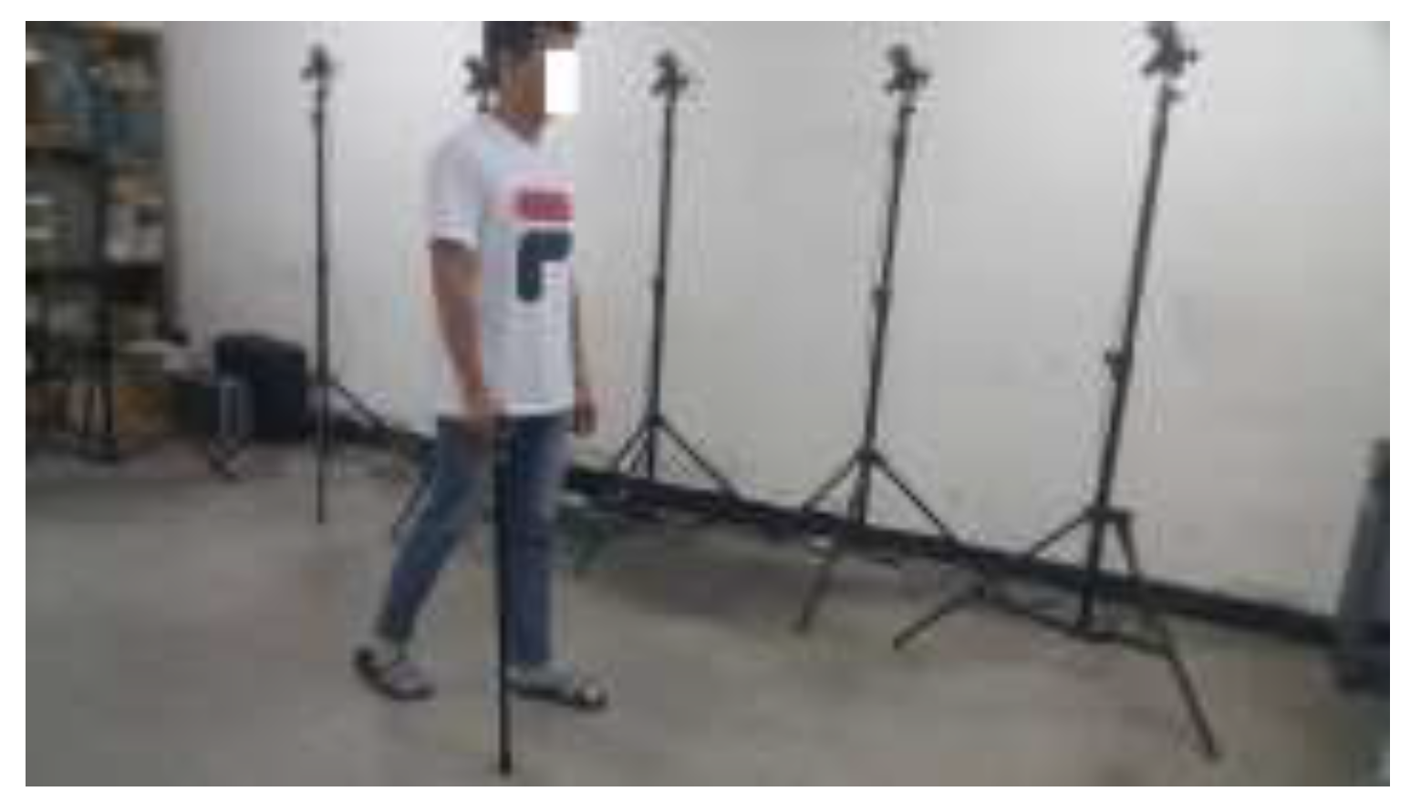
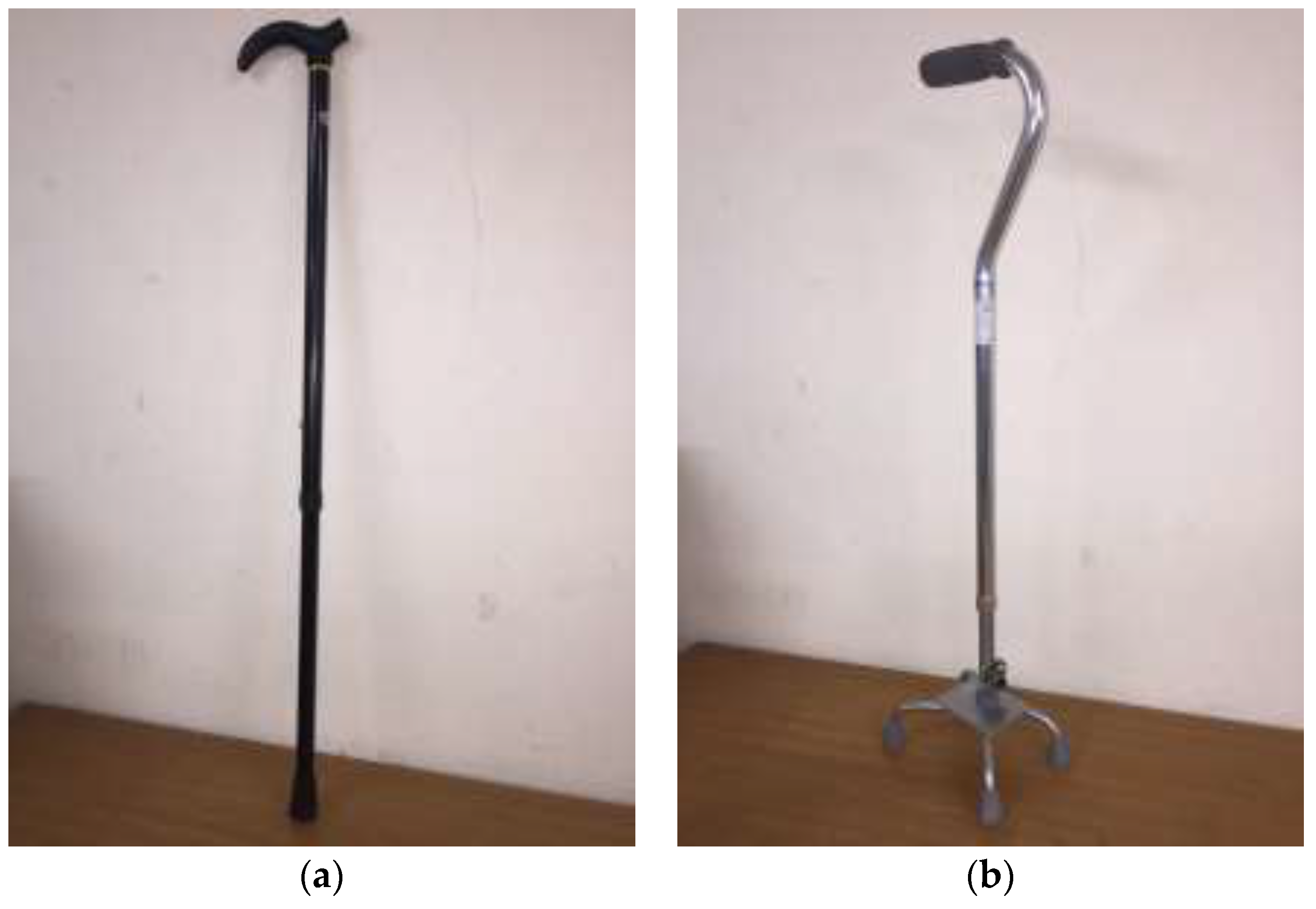
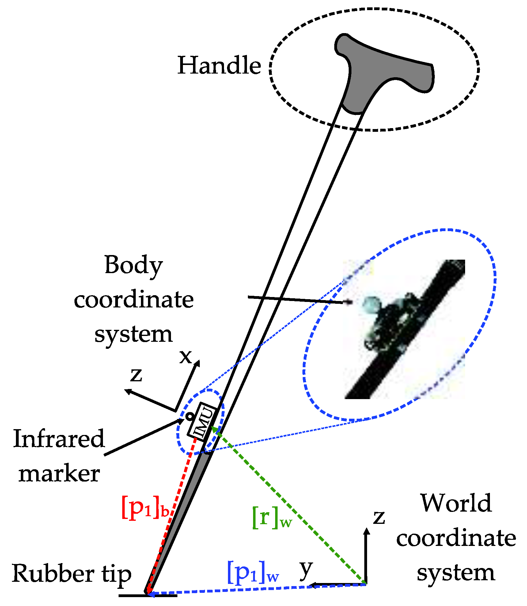
2. System Description
Several types of canes are available in many shapes and sizes, and we investigated two types: a standard cane and a quadripod cane (or quad cane) [9] (see Figure 1).
Figure 1.
Two basic types of cane: (a) Standard cane; (b) Quadripod cane.
A standard cane or straight cane is generally made from inexpensive and lightweight materials such as wood or aluminum. The height of an aluminum cane can be adjusted. A standard cane can help with the balance for someone who does not need strong weight-bearing support [20].
A quadripod cane is a four-legged cane that can stand freely on its own. It provides a larger base of support and provides more weight bearing through the upper extremities. However, all four tips of the cane must be in contact with the ground at the same time for proper use [20].
The proposed system consists of an inertial sensor unit that is firmly attached to the body of a standard aluminum cane (see Figure 2). The cane is equipped with a rubber tip and a handle on top to minimize the shock when walking. An Xsens MTi1, which is an inertial measurement unit (IMU), is mounted on a customized board with Bluetooth communication and SD card storage. The IMU has a three-axis accelerometer, three-axis gyroscope, and three-axis magnetometer. To provide reference measurements, there is an infrared marker for an optical tracker system is put on the surface of the IMU and coincides with the origin of the sensor module.
Figure 2.
Standard cane with an attached inertial sensor and infrared marker.
We use two additional duplicate measurement units attached to different positions on the standard cane, and one additional unit on a quadripod cane for performance analysis.
Two coordinate systems are used: the body coordinate system {B} associated with the IMU and the world coordinate system {W}, which is a fixed reference coordinate system. It is assumed that the z-axis of the world coordinate frame is parallel to the direction of local gravitational acceleration and pointing upward. The y-axis of this frame is chosen to point in the walking direction. The three axes of the body coordinate system coincide with the three axes of the inertial sensor (see Figure 2).
Let [p1]b ∈ ℝ3 and [r]w ∈ ℝ3 be 3-D vectors that represent the position of the tip of the cane and the inertial sensor (and the infrared marker), respectively. The subscript b is used to denote the representation in the body coordinate system. Similarly, subscript w is used for the world coordinate system.
3. Methodology
The main objective of this work is to estimate walking distances from sensory information. There are basically three approaches for walking distance estimation using sensors mounted on the foot, waist, or wrist. The indirect method counts the number of strides traveled and the time interval between each two consecutive strides (or one step interval). Assuming that the user performs continuous walking with small variation in speed, the walking distance can be estimated using a linear relationship between the walking step length and the walking rate [21,22]. This algorithm is very simple, but the accuracy is not guaranteed due to the various assumptions.
The second method is based on successive double-integral-based step length estimation from acceleration. The major drawback of this technique is that error rapidly accumulates over the integration time. However, this problem can be partially solved by using a measurement update scheme called zero-velocity updates (ZUPT), where the estimation error can be compensated or reset during the zero-velocity intervals [23].
Another recent method applies a verified relationship between the vertical acceleration and step length to obtain the walking distance by summing all step lengths during travel [24]. However, this method also relies on the assumption of continuous walking and normal walking speed.
In this study, the movement of the measurement unit on a cane is different from cases where a sensor module is attached to a human body. Thus, we used the double integration method to estimate the step length with measurement updating in a Kalman filter based on the ZUPT method. The walking distance is then calculated by summing the total walking step lengths. Recent research has focused on estimating the position in 2D or 3D, but our goal is estimating the walking distance and z-axis position since there is no heading correction method in our algorithm.
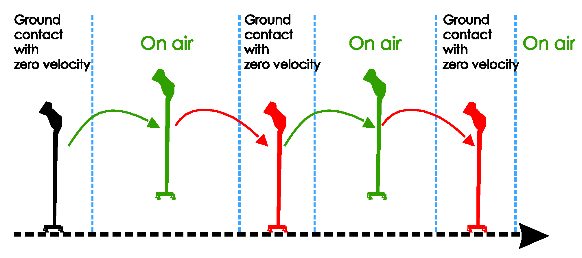
3.1. Cane Movement and Walking Phase Detection
The movements of different types of canes during walking are not the same. A quadripod cane’s movement is dominated by translation movement, while a standard cane’s movement is more similar to that of the human foot. A quadripod cane has four legs that are in contact with the ground for a long period. Therefore, there are zero-velocity intervals and they do not depend on the location of the sensor on the cane. However, a standard cane has only one point that is in contact with the ground. If the sensor unit is mounted exactly at the contact point, we can detect the zero-velocity intervals during walking by using similar detection methods to those used for foot-mounted sensors. However, it is virtually impossible to install a sensor at this position. In this section, we compare the two types of canes in terms of how they move and analyze the output of sensors attached to them.
There are many ways to classify the current state of the cane using data from inertial sensor outputs. One simple solution is feature extraction based on the norms of gyroscope and accelerometer output, which is similar to gait phase classification [22,23]. These states and the transitions between them are sometimes not clearly distinguished due to unexpected user behaviors. However, this can be neglected by using a machine learning approach with additional data from other types of sensor sources such as a force sensor [10], but this requires more computational power. In our work, we used a simple algorithm based on a set of thresholds on different quantities of sensor outputs with some additional constraints to classify different phases of the walking action with canes (see Section 3.3).
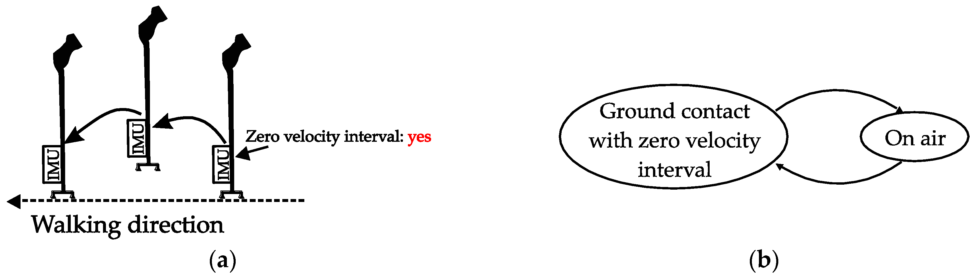
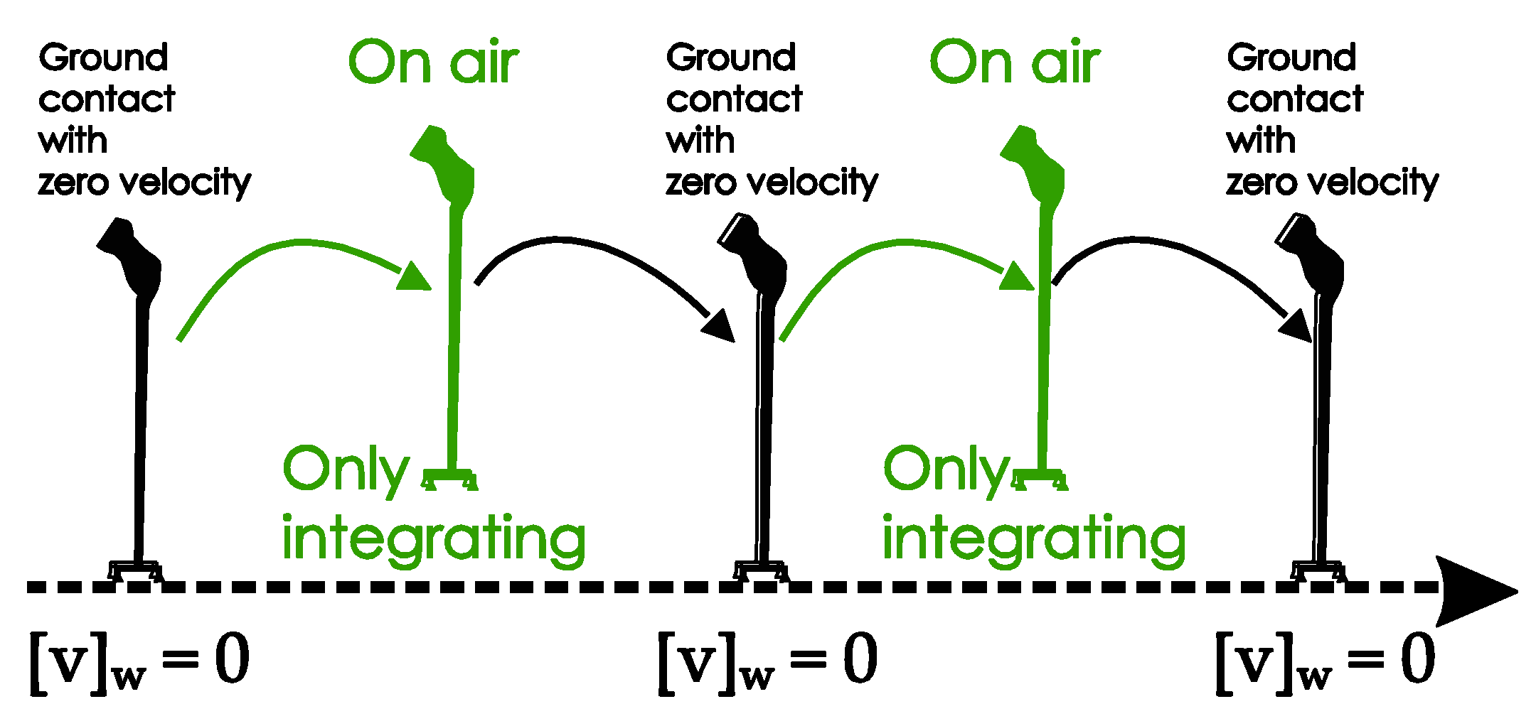
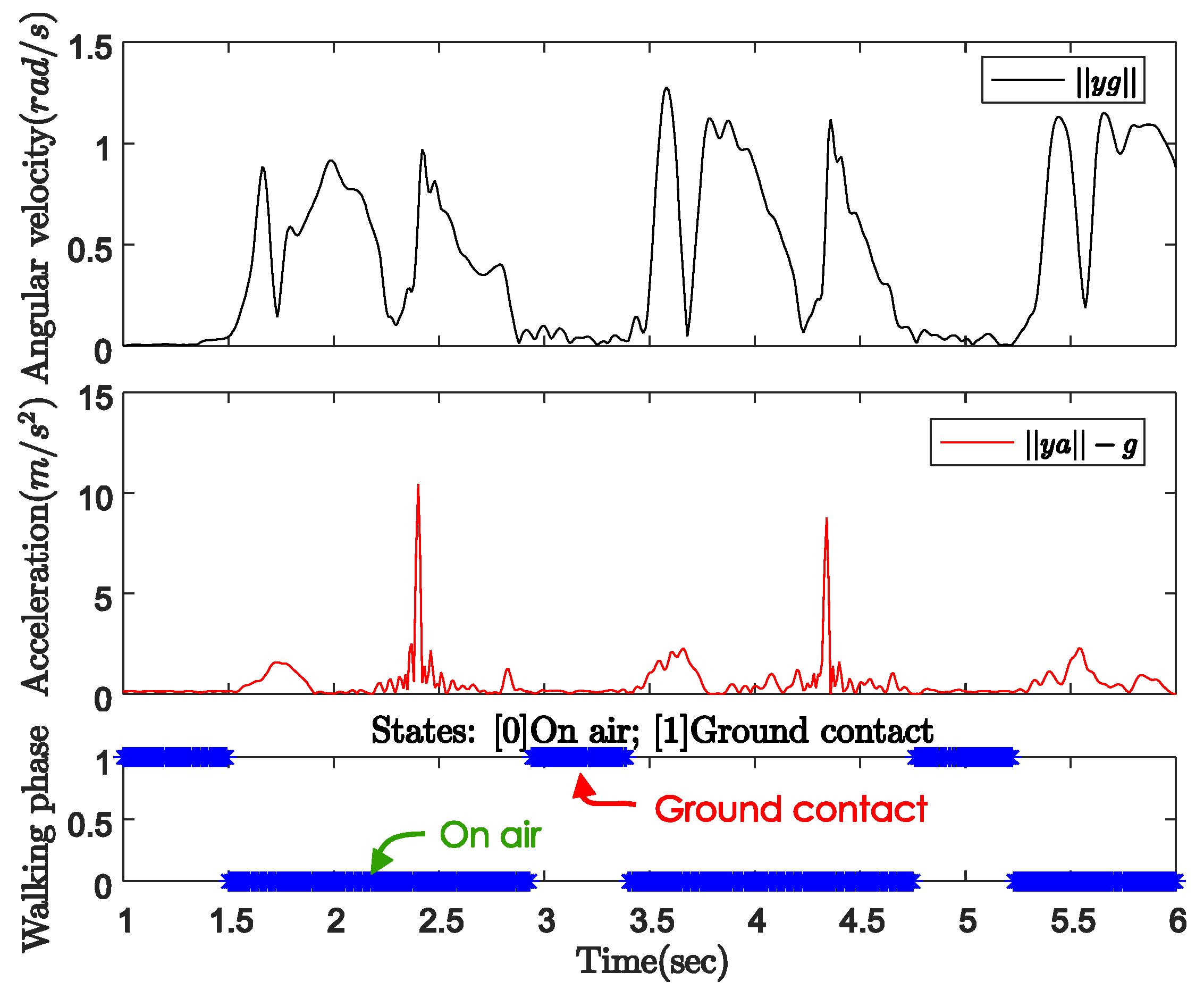
3.1.1. Quadripod Cane
As shown in Figure 3, the movement of a quadripod cane during walking can be separated into two phases:
Figure 3.
Quadripod cane movement: (a) Visualization; (b) State diagram.
- Ground contact (with zero-velocity interval): All four legs are on the ground and the cane is not moving. There is no rotation of the sensor unit during the ground contact.
- On air: The legs are not on the ground and the cane is freely moving.
Figure 4 shows the norms of the gyroscope and accelerometer output during normal walking with a quadripod cane. In this case, the sensor unit can be attached anywhere on the body of the cane. The cane is left standing by itself before the user starts walking. We can see the same pattern of sensor output norms in both the periods before walking (from 3 to 3.6 s) and during ground contact (from 5.2 to 6 s) while walking. In these intervals, the angular velocity norm is almost zero, which means there is no rotation movement. The acceleration norm is approximately equal to gravitational acceleration since there is only sensor noise but no movement. As the cane takes off from the ground until the next moment of ground contact (on air period), both the gyroscope and accelerometer outputs have larger positive norms.
Figure 4.
Gyroscope and accelerometer output norms with quadripod cane.
Figure 5 indicates the three-axis angular velocity corresponding to that of the sensor output in Figure 4. The angular velocity is dominated by a fixed-axis rotation (y-axis). During the ground contact period, the gyroscope outputs along all three axes are zero with some small sensor noise. Therefore, as shown in Figure 6, we can detect the walking phases with a quadripod cane based on the accelerometer and gyroscope outputs as follows:
Figure 5.
Three-axis angular velocity from gyroscope output with quadripod cane.
Figure 6.
Quadripod cane’s movement patterns.
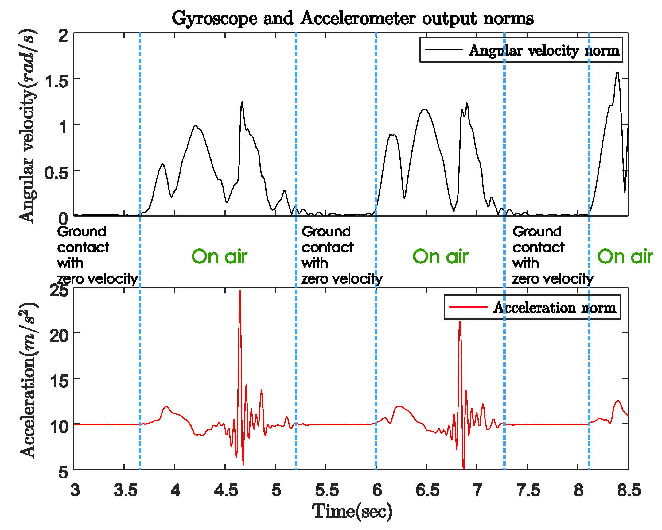
- Ground contact (with zero-velocity interval): No external acceleration and no angular velocity, only affected by gravitational acceleration.
- On air: Contains the contact shock moment, and acceleration and angular velocity are significant.
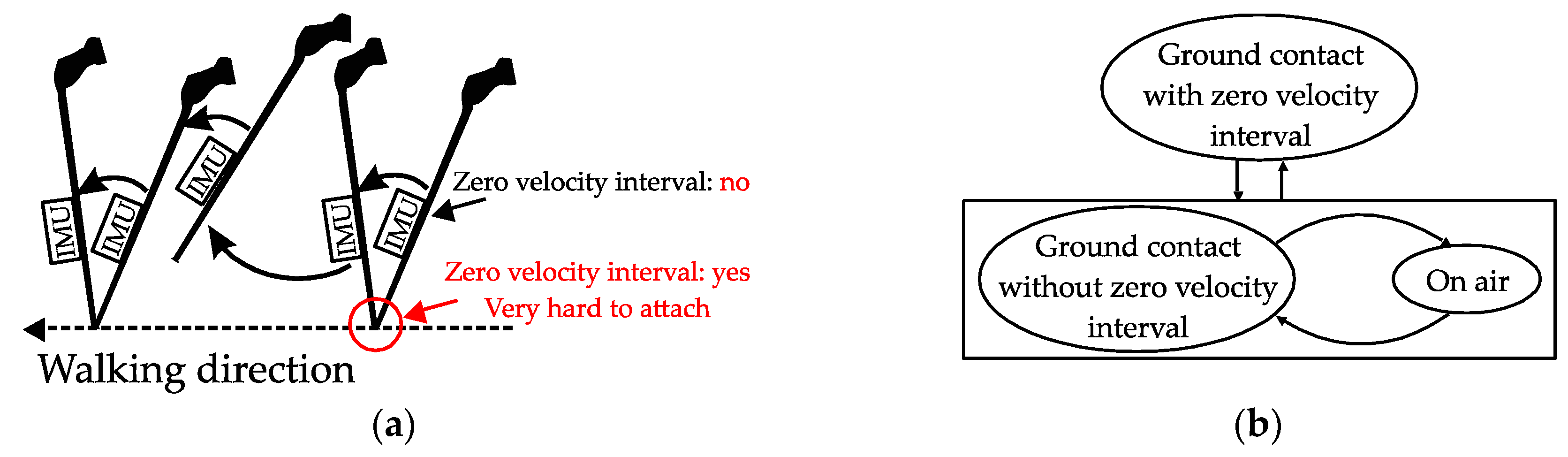
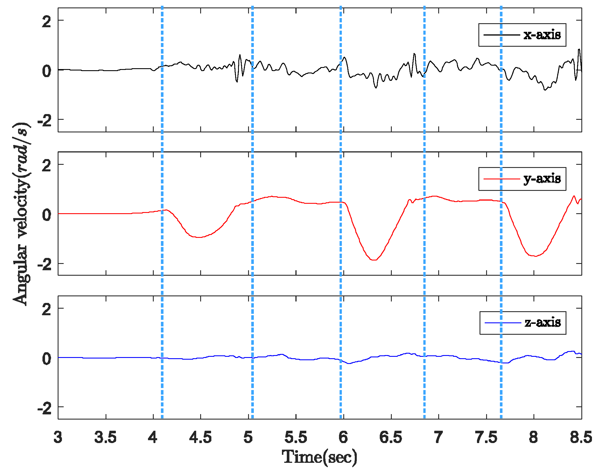
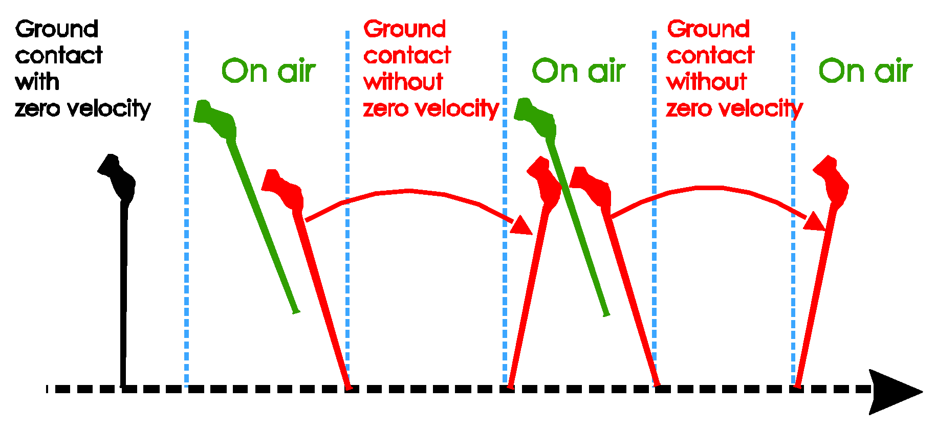
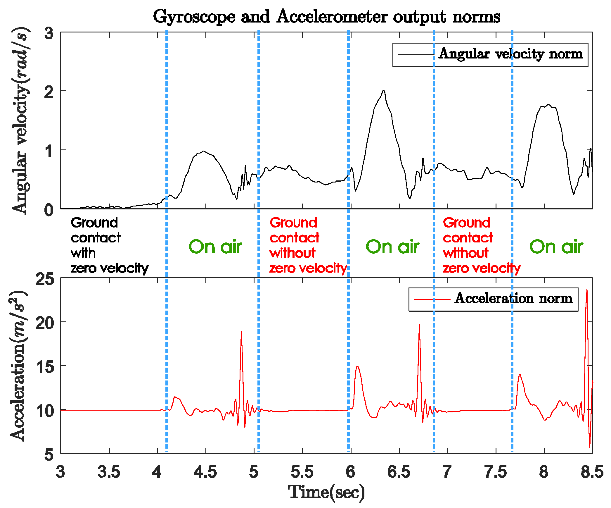
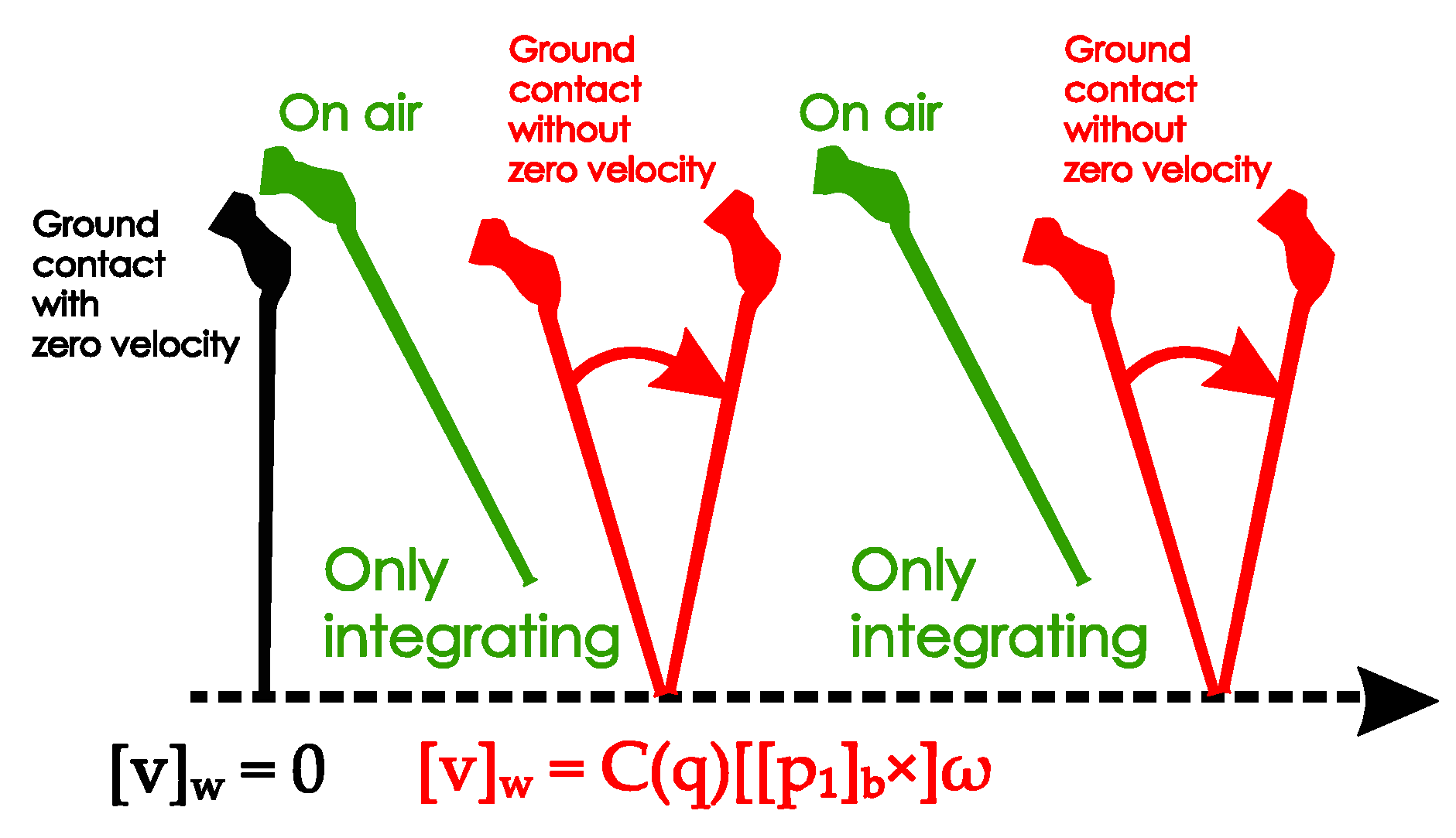
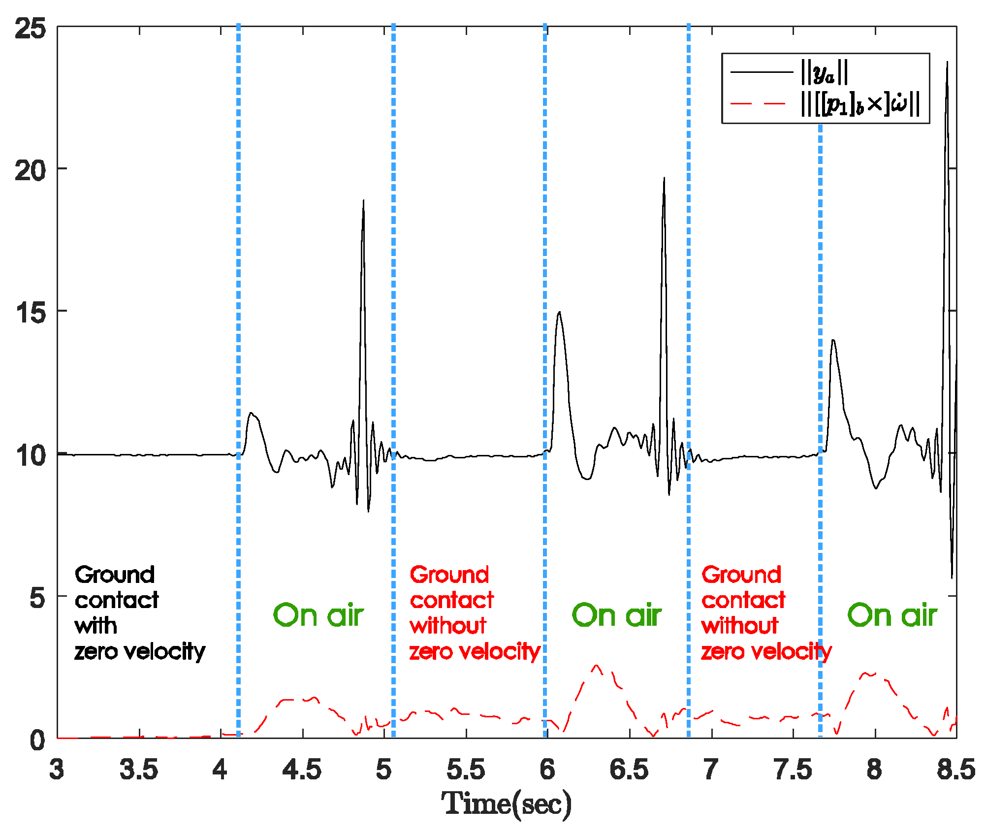
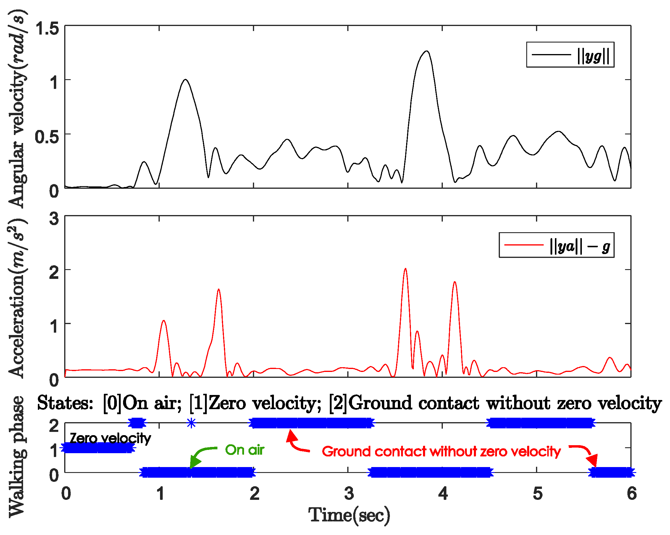
3.1.2. Standard cane
The movement of the standard cane while walking can be divided into three phases, as shown in Figure 7:
Figure 7.
Standard cane movement: (a) Visualization; (b) State diagram.
- Ground contact with zero-velocity interval: the cane’s tip is on the ground and the cane is not moving or swinging.
- On air (swing): the cane’s tip is not on the ground and the cane is freely moving.
- Ground contact without zero-velocity interval: the cane’s tip is on the ground and the cane movement can be modeled as an inverted pendulum.
Figure 8 shows the norms of the gyroscope and accelerometer output during normal walking with a standard cane. In this case, the sensor unit can be attached anywhere near the tip of the cane. The user was standing still with the cane straight down to the ground before starting walking. Figure 9 shows the three-axis angular velocity corresponding to that of the sensor outputs in Figure 8. The experiments revealed a typical pattern, as shown in Figure 10.
Figure 8.
Gyroscope and accelerometer output norms with standard cane.
Figure 9.
Three-axis angular velocity from gyroscope output with standard cane.
Figure 10.
Standard cane’s movement patterns.
In the beginning when the cane is not moving, the angular velocity norm is almost zero, and the acceleration norm is equal to gravitational acceleration since there is no movement. As the cane takes off from the ground, both the gyroscope and accelerometer outputs have larger positive norms. Lastly, from the moment of contact until the cane takes off again, the dominant movement is rotation. Therefore, the angular velocity norm still has a large positive value when the acceleration norm is approximately constant near the gravitational acceleration (see Figure 8).
In Figure 9, the angular velocity is dominated by a fixed axis rotation (y-axis) when the sensor module is attached to the body of the cane. During ground contact periods with or without zero-velocity intervals, the gyroscope outputs along the y-axis are assumed to be constant at different levels. Therefore, we can briefly describe the walking phases as follows:
- Ground contact with zero-velocity interval: No external acceleration and no angular velocity.
- Ground contact without zero-velocity interval: Occurs after contact shock moment, very small external acceleration, angular velocity can be assumed as constant.
- On air (swing): Before contact shock moment, acceleration and angular velocity are significant.
3.2. Standard Inertial Navigation Using Indirect Kalman Filter
In this section, the positions of the cane’s tip and the sensor are estimated using an inertial navigation algorithm, which was used in a previous study [23]. The indirect Kalman filter is applied with measurement update during ground contact time (see Section 3.4).
The inertial sensor unit’s output data consists accelerometer output ya ∈ ℝ3 and gyroscope output yg ∈ ℝ3, which are represented in the body coordinate system as:
where represents a rotation from the body (sensor) coordinate system to the world coordinate system; a ∈ ℝ3 is the acceleration produced by force other than the gravitational field; ω ∈ ℝ3 is the body angular rate; and ba,bg ∈ ℝ3 are the accelerometer and gyroscope bias, respectively. is defined by:
where g is the gravitational acceleration. The sensor noise ua,ug ∈ ℝ3 are assumed to be zero-mean white Gaussian noise satisfying:
A quaternion q ∈ ℝ4 is used to represent the rotation between the world and body coordinate systems. It is related to rotation matrix as:
Let r = [r]w ∈ ℝ3 and v = [v]w ∈ ℝ3 be the position and velocity of the sensor in the world coordinate system. The basic equations for inertial navigation are:
where is defined by:
Since the position and velocity can be derived from sensor data using (1) and (2), we can use either a direct Kalman filter or indirect Kalman filter for the navigation algorithm. In a direct Kalman filter, r and q are included in the state and are directly estimated in the filter. In an indirect Kalman filter, r and q are computed using (2), where yg and are used in place of ω and [a]b, respectively. Since yg ≠ ω and due to the noise in (1), the computed values contain some error, which is estimated in an indirect Kalman filter. Among two type of filters, it seems that the indirect Kalman filter is more popular since the number of state is smaller and there is no required assumption for the derivative of ω [25]. In this paper, a quaternion-based indirect Kalman filter is used for both the standard algorithm and the proposed algorithm.
Let be the computed values of q,v,r, using (2):
Due to the measurement noise ug and ua, there is error in the estimation of . The errors in and are ve and re, defined by:
The error in can be expressed using the multiplicative quaternion error. The quaternion error satisfies the following expression:
or the equivalent representation:
where is the quaternion multiplication operator. We assume that is small and can be approximated by:
We can also approximate when qe is small using the following equation:
where is defined by:
The state variable of an indirect Kalman filter are defined by:
The state equation is:
where the covariance matrix is:
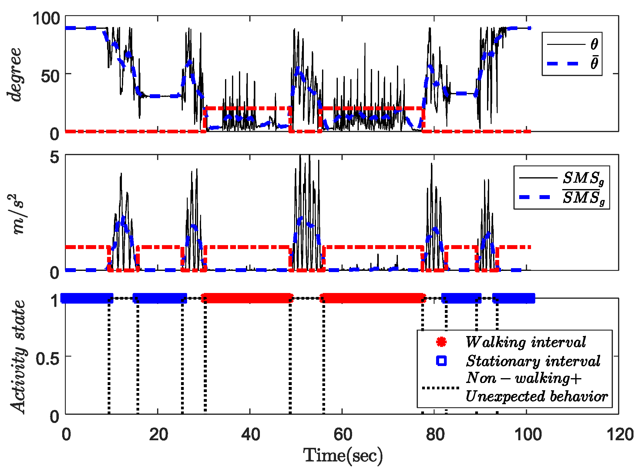
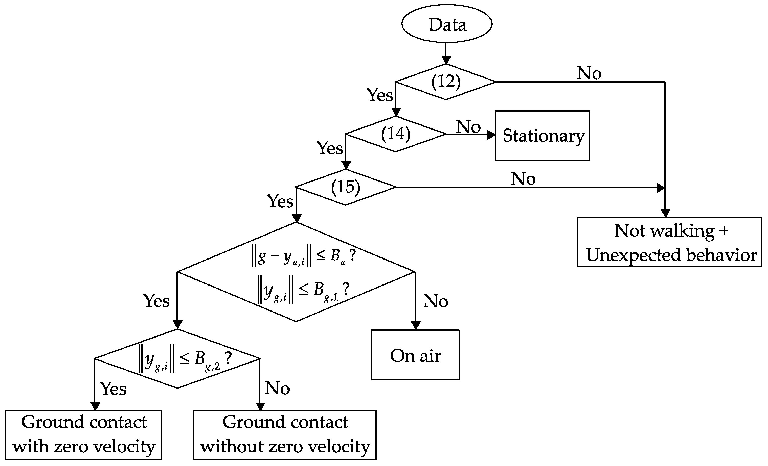
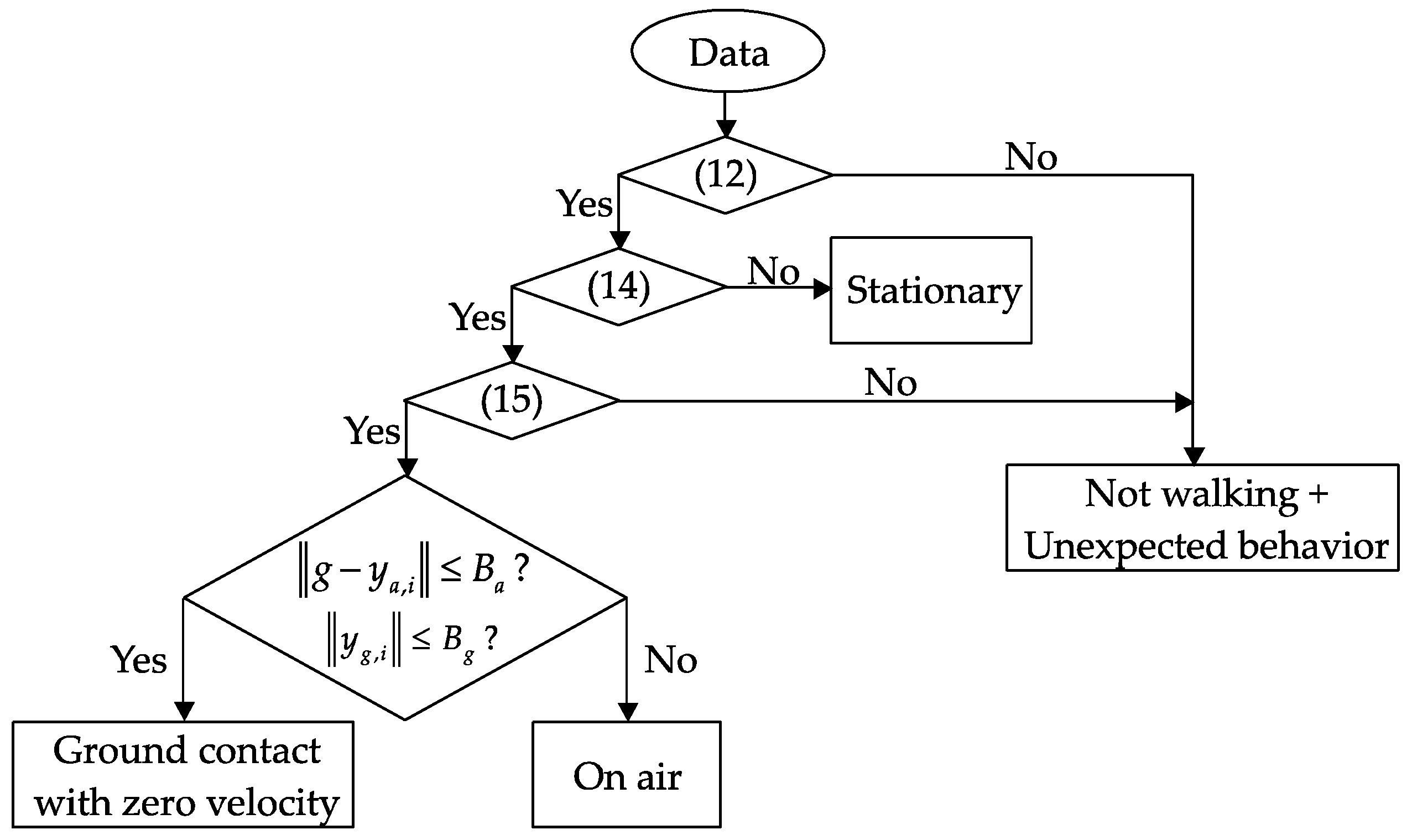
3.3. Walking Phase Classification
The first step to estimate the walking distance is to detect whether a person is walking or not. During walking, the movement is constrained (the cane rotation axis is constrained), and the angle between the cane and vertical direction are within a certain range.
For the movement constraint, the cane rotations are dominated by vertical rotations when changing the walking direction and lateral rotations when the cane swings during walking. This means that the gyroscope signals are mostly concentrated on the x-axis and y-axis. To check whether this condition is satisfied, signal magnitude subtraction (SMS) of the gyroscope output is introduced, which involves subtracting the xy-axis gyroscope signal from the angular velocity norm:
where and are the angular velocity along the x-axis and y-axis of the sensor coordinate frame, and is the angular velocity norm.
The discrete time k is assumed to be part of either the walking interval or the stationary interval if the following condition is satisfied:
where Bsms is a threshold and Nsms is an integer. Otherwise, k is part of non-walking periods.
For the cane angle condition, the x-axis of the sensor coordinate frame (Figure 2) and the upward vertical direction make an acute angle during walking. The cane’s angle is calculated from the acceleration signal:
where and are the acceleration along the three axes of the sensor coordinate frame.
The cane is assumed to point downwards if the following condition is satisfied:
The proposed algorithm detects walking movement based on the following criteria:
- First criterion: a walking interval is detected using (12) and (14).
- Second criterion: the duration satisfies:
where ks and ke denote the start and end points of a walking interval (detected by (12) and (14)).
An experiment was performed to assess the performance of the proposed method. A subject was asked to use the standard cane and perform the following actions:
- The cane is lying on the table
- Lifting the cane up and doing some random waving actions
- Leaning the cane on the table
- Lifting and holding the cane against the ground and preparing to walk
- Walking along a straight line
- Stopping and turning around
- Standing still and doing some waving actions
- Stopping waving and starting to walk freely
- Stopping walking and doing some waving actions
- Stopping waving and leaning the cane on the table
- Lifting the cane up and putting it on a table.
The walking interval detection results are shown in Figure 11. The upper and middle graphs show the calculated cane angle, the SMS signal, and the condition outputs (red lines). The activity classification results are shown in the bottom graph. The results show that the actions 1, 3, 10, and 11 contain stationary intervals. The actions 2, 4, 7 and 9 contain non-walking intervals and unexpected behaviors. The remaining periods, including actions 5, 6, and 8 are assigned as walking intervals. The results show that the proposed algorithm can classify the walking movements correctly.
Figure 11.
An example of activity classification. Upper graph: Cane angle θ. Middle graph: SMS signal. Bottom graph: Activity classification result.
After detecting walking periods, we need to classify the walking phases and update the measurements to eliminate the estimation error. For both the quadripod cane and standard cane, we use similar methods to detect the ground contact phases and swing phases (on air) based on the accelerometer and gyroscope output.
For each sampling time k, we evaluate the following conditions:
where g is standard gravity, the parameters Ba and Bg are thresholds, Na and Ng specify time intervals.
In the case of quadripod cane, the zero-velocity intervals coincide with the ground contact intervals and are detected if there is no external acceleration and no angular velocity. Therefore, at any time, if the angular velocity norm is smaller than one threshold value and the acceleration norm is near the standard gravity for more than a specified time (both (16) and (17) are satisfied), it can be assigned as ”ground contact with zero velocity”. The remaining periods after all of ground contact periods are detected are assigned as “on air” or swing phases. Figure 12 shows a flowchart of the walking phase classification algorithm for the quadripod cane.
Figure 12.
Flowchart of walking phase classification for a quadripod cane.
With the standard cane, the detection is different since the zero-velocity intervals do not always coincide with the ground contact phases. The ground contact phases in this case (with or without zero-velocity intervals) can be separated from swing phases using similar conditions to those applied for the quadripod cane (see Figure 13). The intervals of ground contact with zero velocity, which occur before and after walking, can then be detected with a stronger condition for the angular velocity norm. This is understandable since such intervals occur during walking with very small external acceleration, and angular velocity is generated due to the inverted-pendulum-like movement of the cane. The remaining periods, which have very small external acceleration and small angular velocity, are assigned as the “ground contact with zero velocity” intervals.
Figure 13.
Flowchart of walking phase classification for a standard cane.
3.4. Measurement Updating
For the quadripod cane, the linear velocity of the sensor module is zero during the ground contact phases with zero velocity. Then if both Equations (16) and (17) are satisfied, the measurement update equation is:
where uk is the measurement noise:
The update procedure is shown in Figure 14:
Figure 14.
Velocity updating procedures for a quadripod cane.
For the standard cane, we do not have the actual zero velocity of the sensor module since the cane is moving during the ground contact phases of walking. However, the tip of the cane, which is the only contact point, is not moving in those periods. The velocity of the sensor unit can be estimated using the inverted pendulum model.
The position of the cane’s tip in the world coordinate system (see Figure 2) is:
When the tip is on the ground, is constant. Therefore, taking the derivative of (19) leads to:
Using the following property:
we have:
and the velocity of the sensor unit is:
Before and after the walking, the cane’s tip is on the ground and the cane is not moving, and both conditions (16) and (17) are satisfied. The corresponding velocity of the inertial sensor unit is zero. The measurement update equation is:
where is the measurement noise
If only (16) is satisfied at discrete time k, then there is no zero-velocity interval. Hence, the cane is moving as an inverted pendulum while the tip is on the ground. The corresponding velocity of the sensor unit is updated using (22) as follows:
where is also the measurement noise:
The update procedure is shown in Figure 15:
Figure 15.
Velocity updating procedures for a standard cane.
3.5. Walking Distance Estimation Based on Measurement Update
With the quadripod cane, the external acceleration and angular velocity affecting the sensor unit are almost zero during ground contact since there is no linear or rotational movement. Hence, we applied the standard inertial navigation algorithm (Section 3.2) using Equation (3) to estimate the position and velocity of the sensor module. The walking distance is then calculated by summing the walking step lengths between two consecutive ground contact moments.
Let Sj and Ej be the starting and ending indices of the j-th walking step. The step length SLj and walking distance WL can be computed as follows:
For the standard cane, we need to investigate the effect of the swing motion to reduce the error of the estimation. Taking the derivative of (22) leads to:
Therefore, the accelerometer output can be modeled as:
The acceleration ya in Equation (28) is only gravitational acceleration if the angular velocity ω is constant. In other words, the external acceleration is very small and can be neglected in the ground contact periods (with or without zero velocity) based on the assumption that the angular velocity of the sensor unit is constant during the swing phases. We plotted data from the sensor outputs (Figure 16) and compared the acceleration norm with the external acceleration (the second part in Equation (28)). In the intervals mentioned above, the external acceleration caused by movement is significantly smaller than the gravitational acceleration. Therefore, the assumption is acceptable, and the standard inertial navigation algorithm can still be used to estimate the sensor unit’s velocity and position.
Figure 16.
Acceleration norm and external acceleration.
In a scenario where the ground is flat and has zero slope, we can also include the z-axis position of the tip in the state variable of the Kalman filter as a measurement that is updated using (6), (8), and (19) in the following estimation:
4. Experiments and Results
Experiment results are presented to verify the proposed method. In the first experiment, a subject walked 10 times with the quadripod cane along a 3-m path within the working range of an optical tracker system (see Figure 17). The sensor module and an infrared marker are attached at the same place on the body of the quadripod cane. Both the inertial sensors and camera system are configured to have output data at 100 Hz.
Figure 17.
Continuous walking within the working range of an optical tracker system.
One of the results is given in Figure 18 with the sensor outputs and zero-velocity intervals, which are detected using (16) and (17) with the following parameters:
Figure 18.
Quadripod cane’s output data and zero-velocity intervals.
Table 1 shows the estimated walking distances using standard inertial navigation algorithm with zero-velocity updating and the reference values obtained from the optical tracker system. During zero-velocity intervals, there is no movement of the quadripod cane, so the angular velocity is very small (almost zero) and the acceleration is near gravitational acceleration. The average absolute error is about 9.8 cm, while the maximum error is about 13.4 cm.
Table 1.
Quadripod cane’s estimated and reference walking distance.
In the second experiment, a similar procedure to the first experiment is repeated with the standard cane. Three sensor modules and three infrared markers are firmly attached at three different positions (32) on the body of the standard cane. The parameters used in the algorithm are:
One of the results with sensor output norms and walking phase classification results is given in Figure 19.
Figure 19.
Standard cane’s output data and activity classification.
Figure 19 shows that zero-velocity intervals occur only right before and after walking, which means the standard cane moves like an inverted pendulum during the whole ground contact phase. The gyroscope’s output norm during ground contact without zero velocity is smaller than that during the swing (on air) phase but not near zero anymore. Table 2 presents the results for the three different positions of the sensor modules. The results are quite good with a mean absolute errors for each case of about 5.0, 6.2, and 18.6 cm. The closer the sensor module is to the contact point; the better estimated results are. This is not surprising since the acceleration caused by the rotational movement during the ground contact phase is reduced when the sensor module is attached near the contact point.
Table 2.
Standard cane’s estimated and reference walking distance.
A third set of experiments was performed to verify the accuracy of our algorithm for long-distance walking with both types of canes. One sensor module is mounted on each cane at the same position as in the previous experiments, and the standard cane has the sensor module at the lowest position [p1]b. An additional sensor module is attached to the right foot of the user. Five people walked five times along a total of 170 m in a flat corridor with zero slope. Each time, the participant walked along 85 m, turned around, and came back to the starting position. Similar parameters to the second experiment were chosen. The method for updating the z-axis position in Section 3.5 was also used to verify the performance of the algorithm, and the results are given in Table 3 and Table 4.
Table 3.
Estimated walking distance from 170-meter experiment with quadripod cane.
Table 4.
Estimated walking distance from 170-meter experiment with standard cane.
The estimated results of our algorithm are compared with the walking distance calculated from the foot-mounted sensor data using the standard inertial navigation algorithm. One estimated position with two updating methods is given in Figure 20. The result is quite good, and the maximum error for the quadripod cane is 114.2 cm (0.67%) and for the standard cane is 215.4 cm (1.27%). The maximum error of the foot-mounted sensor is 271.6 cm (1.60%).Figure 20 shows that the error in the z-axis position of the tip is corrected using our method, which included Equations (29) and (30) in the Kalman filter measurement update. However, there is a little improvement in the xy position since the movement range of the z-axis is not significant (about 10 cm).
Figure 20.
z-axis position estimation: (a) without z-axis updating; (b) with z-axis updating.
5. Conclusions
We have proposed a walking cane device consisting of an inertial sensor and a method for walking phase classification and velocity updating. The system can accurately estimate walking distance when using two types of canes. We can use the standard inertial navigation algorithm with zero-velocity updates for the quadripod cane, but the standard cane’s results show that there is no zero velocity when walking since the moves like an inverted pendulum during the ground contact phase. The maximum estimation error for 170 m of walking was 114.2 cm (0.67%) for the quadripod cane and 215.4 cm (1.27%) for the standard cane.
One drawback of the proposed algorithm is that it does not work in case of dragging and other abnormal situations since there is no measurement updating interval. In these cases, the error will quickly diverge. The proposed system provides a solution for data collection and analysis, which could be helpful for caregivers or doctors during patient rehabilitation.
Acknowledgments
This work was supported by National Research Foundation of Korea Grant funded by the Korean Government (No. 2016R1D1A1A09918657).
Author Contributions
Duc Cong Dang and Young Soo Suh conceived and designed this study. Duc Cong Dang performed the experiments and wrote the paper. Young Soo Suh reviewed and edited the manuscript.
Conflicts of Interest
The authors declare no conflict of interest.
References
- Bruun, G. Mobility aids, proposal for research and development. In Development of Electronic Aids for the Visually Impaired; Emiliani, P.L., Ed.; Springer: Dordrecht, The Netherlands, 1986; pp. 265–273. [Google Scholar]
- Wikipedia Contributors. Mobility Aid. Wikipedia, The Free Encyclopedia. Available online: https://en.wikipedia.org/w/index.php?title=Mobility_aid&oldid=790371055 (accessed on 20 November 2017).
- Bateni, H.; Maki, B.E. Assistive devices for balance and mobility: Benefits, demands, and adverse consequences. Arch. Phys. Med. Rehabil. 2005, 86, 134–145. [Google Scholar] [CrossRef] [PubMed]
- Faruqui, S.R.; Jaeblon, T. Ambulatory assistive devices in orthopaedics: Uses and modifications. J. Am. Acad. Orthop. Surg. 2010, 18, 41–50. [Google Scholar] [CrossRef] [PubMed]
- Salminen, A.L.; Brandt, A.; Samuelsson, K.; Toytari, O.; Malmivaara, A. Mobility devices to promote activity and participation: A systematic review. J. Rehabil. Med. 2009, 41, 697–706. [Google Scholar] [CrossRef] [PubMed]
- Wikipedia Contributors. Population Ageing. Wikipedia, The Free Encyclopedia. Available online: https://en.wikipedia.org/w/index.php?title=Population_ageing&oldid=815340799 (accessed on 20 November 2017).
- Kaye, H.S.; Kang, T.; LaPlante, M.P. Mobility device use in the United States. In Disability Statistics Report (14); Department of Education, National Institute on Disability and Rehabilitation Research: Washington, DC, USA, 2000; Volume 14, p. 60. [Google Scholar]
- Whittle, M.W. Chapter 3—Pathological and other abnormal gaits. In Gait Analysis, 4th ed.; Butterworth-Heinemann: Edinburgh, UK, 2007; pp. 101–136. [Google Scholar]
- Bradley, S.M.; Hernandez, C.R. Geriatric assistive devices. Am. Fam. Phys. 2011, 84, 405–411. [Google Scholar]
- Wade, J.; Beccani, M.; Myszka, A.; Bekele, E.; Valdastri, P.; Flemming, P.; Riesthal, M.D.; Withrow, T.; Sarkar, N. Design and Implementation of an Instrumented Cane for Gait Recognition. In Proceedings of the 2015 IEEE International Conference on Robotics and Automation (ICRA), Seattle, WA, USA, 26–30 May 2015; pp. 5904–5909. [Google Scholar]
- Choi, Y.; Ralhan, A.S.; Ko, S. A study on machine learning algorithms for fall detection and movement classification. In Proceedings of the 2011 International Conference on Information Science and Applications, Jeju Island, Korea, 26–29 April 2011; pp. 1–8. [Google Scholar]
- Dinh, A.; Shi, Y.; Teng, D.; Ralhan, A.; Chen, L.; Dal Bello-Haas, V.; Basran, J.; Ko, S.-B.; McCrowsky, C. A fall and near-fall assessment and evaluation system. Open Biomed. Eng. J. 2009, 3, 1–7. [Google Scholar] [CrossRef] [PubMed]
- Lee, R.Y.W.; Carlisle, A.J. Detection of falls using accelerometers and mobile phone technology. Age Ageing 2011, 40, 690–696. [Google Scholar] [CrossRef] [PubMed]
- Lan, M.; Nahapetian, A.; Vahdatpour, A.; Au, L.; Kaiser, W.; Sarrafzadeh, M. Smartfall: An automatic fall detection system based on subsequence matching for the smartcane. In Proceedings of the Fourth International Conference on Body Area Networks, ICST (Institute for Computer Sciences, Social-Informatics and Telecommunications Engineering), Los Angeles, CA, USA, 1–3 April 2009; pp. 1–8. [Google Scholar]
- Almeida, O.; Zhang, M.; Liu, J.C. Dynamic fall detection and pace measurement in walking sticks. In Proceedings of the 2007 Joint Workshop on High Confidence Medical Devices, Software, and Systems and Medical Device Plug-and-Play Interoperability (HCMDSS-MDPnP 2007), Cambridge, MA, USA, 25–27 June 2007; pp. 204–206. [Google Scholar]
- Huang, J.; Di, P.; Wakita, K.; Fukuda, T.; Sekiyama, K. Study of fall detection using intelligent cane based on sensor fusion. In Proceedings of the 2008 International Symposium on Micro-NanoMechatronics and Human Science, Nagoya, Japan, 6–9 November 2008; pp. 495–500. [Google Scholar]
- Wu, W.; Au, L.; Jordan, B.; Stathopoulos, T.; Batalin, M.; Kaiser, W.; Vahdatpour, A.; Sarrafzadeh, M.; Fang, M.; Chodosh, J. The smartcane system: An assistive device for geriatrics. In Proceedings of the ICST 3rd International Conference on Body Area networks, ICST (Institute for Computer Sciences, Social-Informatics and Telecommunications Engineering), Tempe, AZ, USA, 13–17 March 2008; pp. 1–4. [Google Scholar]
- Au, L.K.; Wu, W.H.; Batalin, M.A.; Stathopoulos, T.; Kaiser, W.J. Demonstration of active guidance with smartcane. In Proceedings of the 2008 International Conference on Information Processing in Sensor Networks (IPSN 2008), St. Louis, MO, USA, 22–24 April 2008; pp. 537–538. [Google Scholar]
- Culmer, P.R.; Brooks, P.C.; Strauss, D.N.; Ross, D.H.; Levesley, M.C.; O’Connor, R.J.; Bhakta, B.B. An instrumented walking aid to assess and retrain gait. IEEE/ASME Trans. Mechatron. 2014, 19, 141–148. [Google Scholar] [CrossRef]
- Van Hook, F.W.; Demonbreun, D.; Weiss, B.D. Ambulatory devices for chronic gait disorders in the elderly. Am. Fam. Phys. 2003, 67, 1717–1724. [Google Scholar]
- Suh, Y.S.; Nemati, E.; Sarrafzadeh, M. Kalman-filter-based walking distance estimation for a smart-watch. In Proceedings of the 2016 IEEE First International Conference on Connected Health: Applications, Systems and Engineering Technologies (CHASE), Washington, DC, USA, 27–29 June 2016; pp. 150–156. [Google Scholar]
- Wang, J.S.; Lin, C.W.; Yang, Y.T.C.; Ho, Y.J. Walking pattern classification and walking distance estimation algorithms using gait phase information. IEEE Trans. Biomed. Eng. 2012, 59, 2884–2892. [Google Scholar] [CrossRef] [PubMed]
- Park, S.K.; Suh, Y.S. A zero velocity detection algorithm using inertial sensors for pedestrian navigation systems. Sensors 2010, 10, 9163–9178. [Google Scholar] [CrossRef] [PubMed]
- Ho, N.-H.; Truong, H.P.; Jeong, G.-M. Step-detection and adaptive step-length estimation for pedestrian dead-reckoning at various walking speeds using a smartphone. Sensors 2016, 16, 1423. [Google Scholar] [CrossRef] [PubMed]
- Suh, Y.S. A smoother for attitude and position estimation using inertial sensors with zero velocity intervals. IEEE Sens. J. 2012, 12, 1255–1262. [Google Scholar] [CrossRef]
© 2018 by the authors. Licensee MDPI, Basel, Switzerland. This article is an open access article distributed under the terms and conditions of the Creative Commons Attribution (CC BY) license (http://creativecommons.org/licenses/by/4.0/).