1. Introduction
A coprime array consists of two uniform sparse arrays, from which a virtual uniform linear array (ULA) can be constructed from the spatial differences between any two sensors [
1,
2]. The spatial autocorrelations at all lags are estimated on the virtual ULA. The increased degrees of freedom has been used to identify
sources from only
physical sensors [
3,
4]. Due to the simplicity of the array configuration, and the ability to resolve many more signals than the number of sensors, coprime arrays have attracted considerable interest in the DOA estimation applications [
5,
6,
7]. In real scenarios, due to multi-path propagation or smart jammers, signals from different DOAs may become partially correlated, or coherent (fully correlated) in the extreme case [
8]. The correlated/coherent signals pose a great challenge to the DOA estimation on coprime arrays. Since the spatial autocorrelations are estimated from the sample mean of the sensor-to-sensor signal multiplications, the presence of coherent signals indicates that the spatial autocorrelations contain cross-terms, which strongly affects the structure of the signal subspace. Incorrect extraction of the signal subspace brings about a failed DOA estimation.
The spatial smoothing preprocessing scheme was developed for a physical ULA to resolve coherent signals [
9]. On coprime arrays, such scheme was employed to construct a correlation matrix for the virtual ULA [
2]. However, the scheme cannot eliminate the cross-terms and hence the coherent signal problem is not solved. Recently, BouDaher et.al. proposed an algorithm to locate coherent targets using an active sensing approach on the coprime multiple-input multiple-output radar [
10]. However, their method cannot be used for the DOA estimation on passive coprime arrays.
The fourth-order (FO) array processing methods were developed for the DOA estimation of non-Gaussian signals [
11,
12]. The main interests in using the FO cumulants relies on the increased degrees-of-freedom provided by the virtual coarray, and the higher resolution brought by the larger effective aperture [
13,
14,
15]. Currently, the FO processing methods are used in coprime arrays [
16] or nested arrays [
17] to increase the virtual aperture. However, as the authors stated, their algorithms cannot handle coherent signals.
In our work, the scenario where the independent and coherent signals coexist is considered. We first formulate an FO cumulant matrix (FCM) with a special form, from which the DOA estimation can be carried out by the fourth-order MUSIC (4-MUSIC) algorithm [
11]. Unfortunately, the FCM cannot be used for DOA estimation of the coherent signals directly. The particular form of the FCM is combined with the array configuration to resolve coherent signals. Since each sparse array is uniform, a series of overlapping identical subarrays can be extracted. Taking one such subarray from each of the sparse arrays, we can build a coprime subarray. An FCM is inherently defined on such coprime subarray, whose size is determined by the subarray sensor numbers. On two similar coprime subarrays, the FCMs share the same structure. Analogous to the spatial smoothing scheme applied to the correlation matrix of a ULA, we propose a generalized spatial smoothing scheme applied to the FCM. When the smoothed FCM is adopted by the 4-MUSIC algorithm, both the independent and coherent signals can be successfully estimated.
Occasionally, the pseudo-spectrum generated from the smoothed FCM encounters a false-peak problem. Some false peaks may appear at the directions where none of the true signals reside, interfering with the extraction of the true signals. We analyzed the causation of this phenomenon. To overcome this challenge, a supplementary sparse array can be added, whose inter-sensor spacing is respectively coprime to each of the existing sparse arrays. On the combined pseudo-spectrum aided by the supplementary sensors, the false peaks are removed.
This paper is organized as follows. In
Section 2, we briefly review the coprime array configuration and then formulate the signal model. In
Section 3, the FO cumulants as well as the form of the FCM are detailed, and the impact of coherent signals on the FCM is investigated. In
Section 4, a generalized spatial smoothing scheme on the FCM is proposed to resolve coherent signals.
Section 5 provides a method to remove the false peaks on the pseudo-spectrum. The effectiveness of the new approach is demonstrated in
Section 6.
Section 7 concludes the paper.
Notations: We use lower-case (upper-case) bold characters to denote vectors (matrices). represents the statistical expectation. and , respectively, denote the transposition and conjugate transposition of a vector or a matrix. is the element-wise complex conjugate. ⊗ denotes the Kronecker product. denotes the rank of a matrix. is the 2-norm of the vector . We use to denote a diagonal matrix that uses the elements of as its diagonal elements.
2. Signal Model
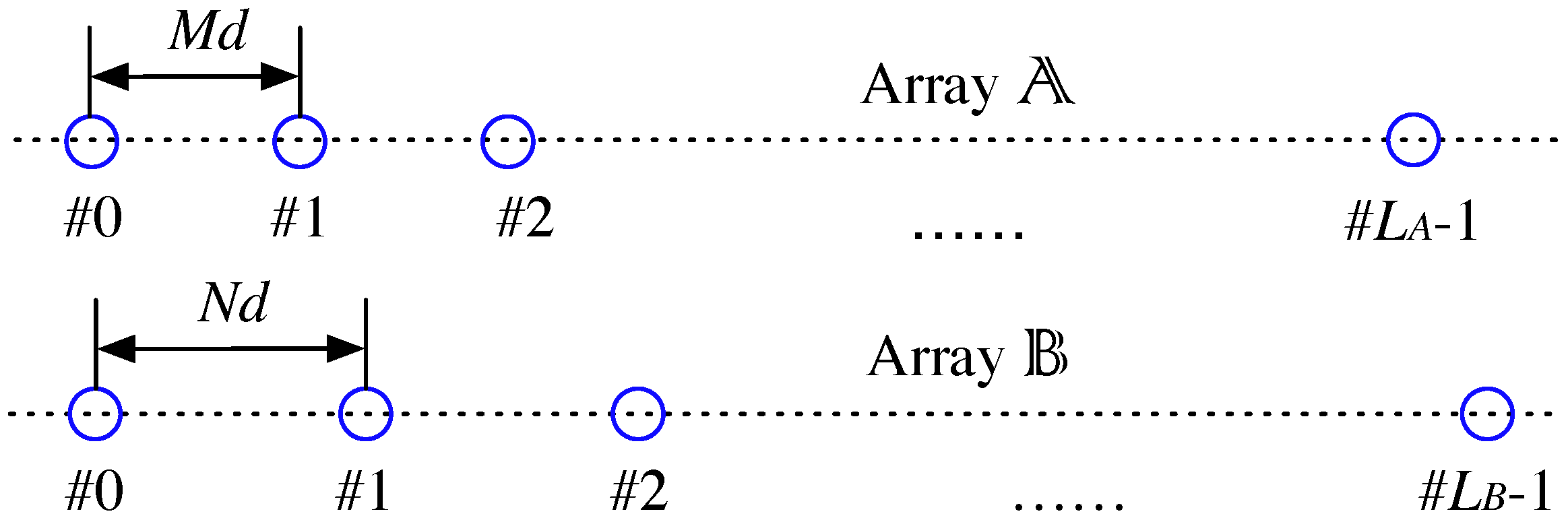
As illustrated in
Figure 1, a typical coprime array consists of two sparse uniform arrays, denoted by Array
and Array
, respectively. Let
M and
N be coprime integers, the sensors of the two sparse arrays are located at (with common sensors for both sparse arrays):
In (
1),
and
are the indices of the sensors, the unit inter-sensor spacing
with
as the half-wavelength, and
and
are the number of sensors of Array
and
, respectively. Typically,
and
. Denote this coprime array by Coarray
.
Suppose a narrowband signal from the DOA
impinges on the coprime array. The normalized DOA of the signal
is defined as
, which indicates the phase difference of the planar wave at the unit spacing
d. The steering vectors of for the individual sparse arrays are
Let
Q narrowband signals impinge on the array from the distinct DOAs
, and the complex amplitude of the
qth signal at snapshot time
t is
. The noise-corrupted measurement vectors on the two sparse arrays are
In (
5),
and
are additive noise,
is the vector of complex amplitudes, and the matrices
and
are the collections of steering vectors of Array
and
, respectively
The assumptions on the signals and noises are listed below.
Suppose that there are
coherent signals in the
gth group (
for the independent signal case and
) with the DOAs
. Since the complex amplitudes of coherent signals are linearly dependent [
9], we can write the group signal vector by
In (
9),
represents the complex coefficients along the respective propagation paths and hence the elements are non-zero.
is a scalar representing the complex amplitude of the source of the
gth group at snapshot time
t.
Because Array
and
are both sparse and uniform, direction ambiguity exists on the sparse arrays. If a collection of
F signals with the DOAs
satisfies
for the distinct non-zero integers
, these DOAs are ambiguous on Array
because their steering vectors are identical
If
F signals are coherent, and their propagation coefficients are
, it is necessary to assume that
This assumption guarantees that the ambiguous signals do not vanish on the individual sparse arrays; otherwise, the collection of coherent signals are cancelled out on Array since holds for every snapshot. In real cases, the probability for a collection of signals to be vanishing is extremely low. We assume that the signals are non-vanishing on both Array and .
In the DOA estimation using coprime array, one needs to estimate
from
snapshots of the measurements
. The existing methods rely on the sensor-by-sensor correlations of the received signal [
1]—for example, the signals on the
th sensor of Array
and the
th sensor of Array
. Suppose the samples on the two sensors (omitting the additive noises) are, respectively,
When the
Q signals are statistically independent,
for
. The correlation becomes
Taking all the integer combinations
,
traverses all the integers between
and
. The rearranged spatial autocorrelations are therefore a superposition of
Q sinusoids on an virtual ULA of size
. A much larger correlation matrix can be constructed to resolve
signals by the subspace-based methods like MUSIC [
1,
2].
However, the presence of coherent signals indicates that
contains cross-terms. For example, if two signals from
and
are coherent, the following component included in the correlation is non-zero:
Since
, the cross-term is not corresponding to any sinusoid component on the virtual ULA. When the rearranged spatial autocorrelations are used to form a correlation matrix as in [
2] or [
18], the signal subspace structure is strongly contaminated, leading to a failed DOA estimation. A demonstrative example of a failed DOA estimation is given in
Figure 4a in the simulations.
Based on the above signal model, in
Section 3, we formulate an FCM of the coprime array signal that can be adopted for the fourth-order DOA estimation. Then, a generalized spatial smoothing scheme, which is crucial for resolving coherent signals from the FCM, is introduced in
Section 4.
4. Generalized Spatial Smoothing on FCM
In this section, we introduce a generalized spatial smoothing scheme applied to the FCM . The scheme leads to a successful estimation of the coherent signals.
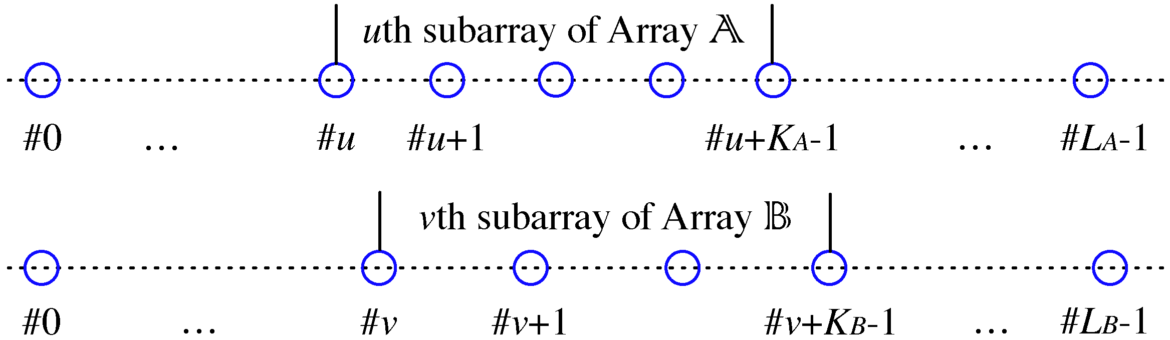
Since the two sparse arrays are both uniform, we can divide each of them, for example, Array
into overlapping subarrays. Every subarray contains
continuous sensors, with sensors
forming the 0th subarray, sensors
forming the 1st subarray, etc. Similarly, Array
is divided into overlapping subarrays of size
. Choosing the
uth subarray of Array
and the
vth subarray of Array
, a coprime subarray can be formed, and is denoted by the
sub-coarray. The subarray indices can be chosen from
and
. An illustration of the
sub-coarray is in
Figure 2.
For a DOA
, the partial steering vectors on the
uth subarray of Array
, and the
vth subarray of Array
are denoted by
The matrices of the collection of partial steering vectors in the
gth group are denoted by
On the
sub-coarray, an FCM is inherently defined analogous to (
25). The size of the sub-coarray FCM is determined by the sub-coarray size
. As in (
31), the sub-coarray FCM can be decomposed into the sum of contributions from each group
Comparing the
uth subarray and the 0th subarray on Array
, and comparing the
vth subarray and the 0th subarray on Array
, a relationship exists between the following matrices:
In (
43),
and
are the
uth and
vth power of the following
diagonal matrices, respectively:
Comparing the
sub-coarray with the
sub-coarray, the following relation exists
where
is a
diagonal matrix. Therefore,
can be written as
We observe that and share the same signal subspace, and are related by a ‘rotation’ of the matrix .
The
generalized spatial smoothed FCM of coprime array is defined as the sum of FCMs on all of the similar sub-coarray:
Denote
as the smoothed FCM of the group complex amplitude vector
, written as
Substituting (
42), (
48) and (
50) into (
49), the smoothed FCM
of the coprime array signal is
In (
50),
is rank-enhanced after spatial smoothing compared to
. Consequently in (
51), the smoothed FCM
is rank-enhanced. The effect of the generalized spatial smoothing scheme on the FCM is analogous to the spatial smoothing scheme on the correlation matrix of a ULA [
9].
An important theorem is in place here. We show that with some restrictions, the vectors for all the signals are in the signal subspace of .
Theorem 1. In the gth group, if and , the vector for any one of the DOAs is in the signal subspace of .
Corollary 1. Let . If , , then the vector for any one of the DOAs is in the signal subspace of the smoothed FCM .
Proof. Following Theorem 1 and that , the signal subspace of is the direct sum of all the signal subspaces of . ☐
Corollary 1 indicates that, if the numbers of overlapping subarrays on both sparse arrays are no less than the largest number of the coherent signals, the vectors
for both the independent and coherent signals are in the signal subspace of
. Then, one can eigen-decompose
to acquire a noise subspace with the projection operator
. The vector
for any signal with a DOA
is orthogonal to the noise subspace. From the smoothed FCM, the null-spectrum produced by 4-MUSIC is defined as
On the pseudo-spectrum , both the independent and coherent signals create peaks at their respective directions.
Remark: the sub-coarray FCM
in (
42) is a principle sub-matrix of the full-coarray FCM
. The indices of columns (and rows) of the principle sub-matrix
in
are
The generalized smoothing process can be accomplished by summing all the proper principle sub-matrices with the indices in (
53) from
.
The generalized spatial smoothing scheme is obviously at the expense of a reduced effective array aperture. In fact, the size of the FCM is , while the smoothed FCM is only . Considering the algorithmic complexity, the eigen-decomposition of the FCM takes operations. The complexity is equivalent to MUSIC on a ULA with a similar extent to the coprime array.
5. Removing False Peaks
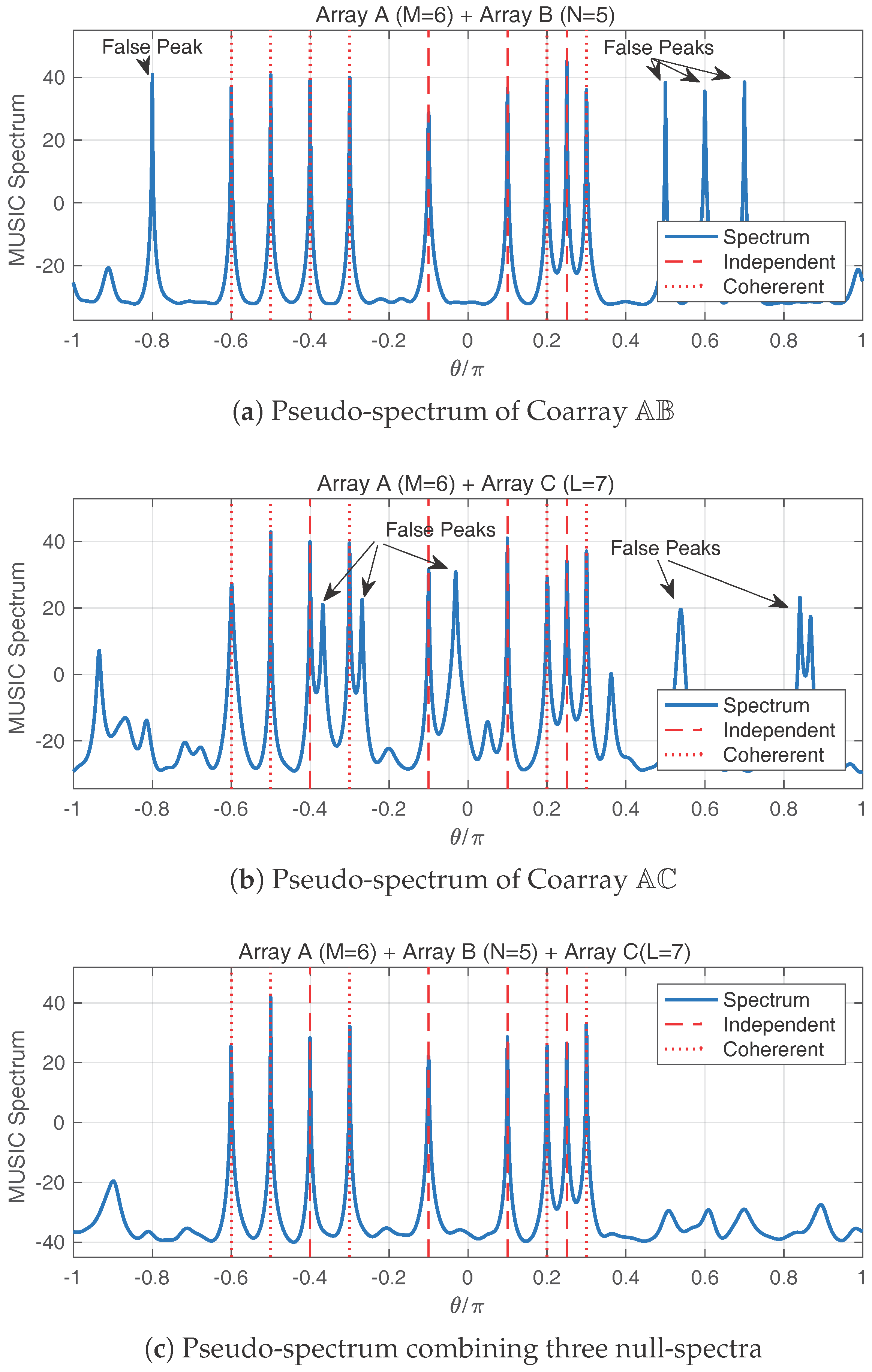
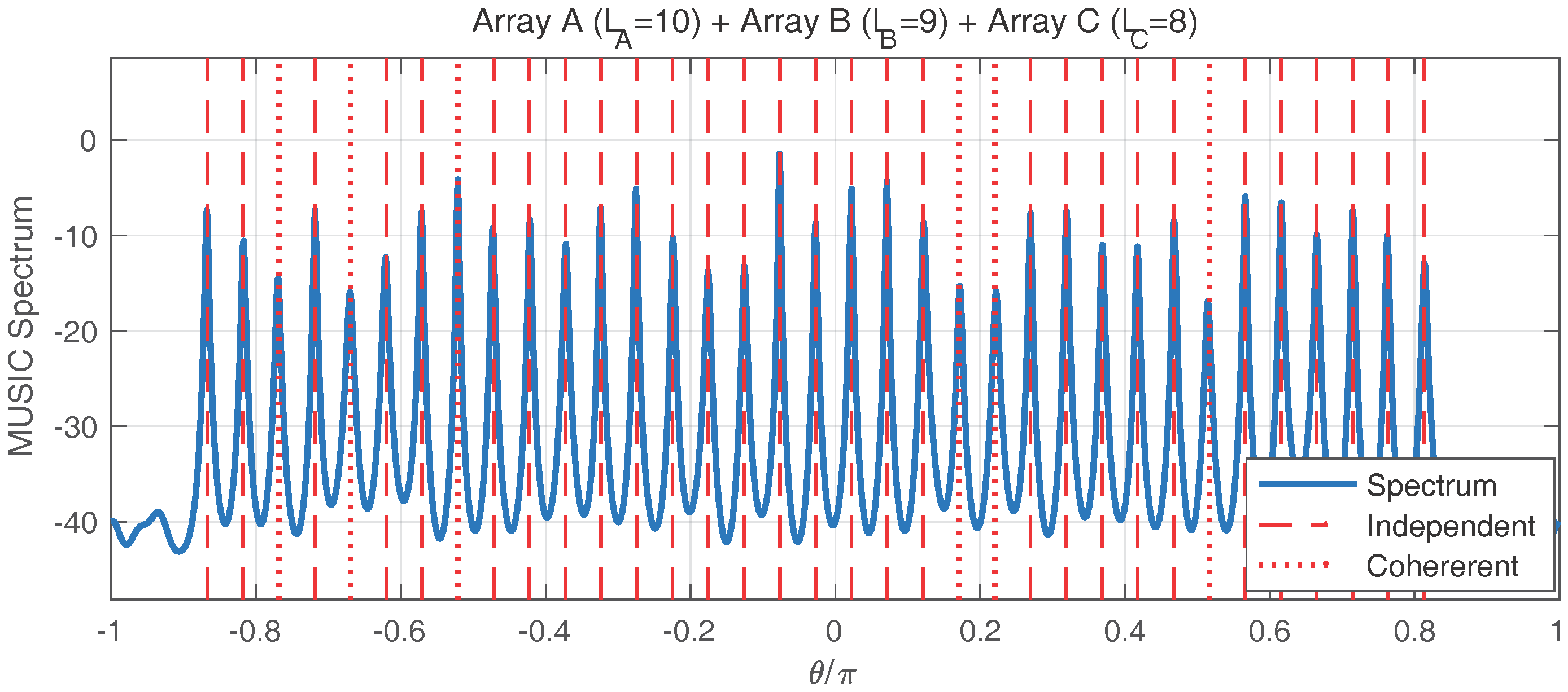
On the pseudo-spectrum from the smoothed FCM, some false peaks occasionally arise at the directions where none of the true signals resides. An example of the false peaks is in
Figure 5 in the simulations. In this section, we explain the false peak phenomenon and provide a technique to remove them.
5.1. Explanation of the False Peaks
When the generalized spatial smoothing scheme is applied to enhance the rank of in (51), not only the vector for the signal DOAs , but also the cross-terms appear in the signal subspace of . These cross-terms are not corresponding to any signal component and should not create peaks on the pseudo-spectrum. However, the steering vectors and are ambiguous due to the sparsity of Array and . We show that a false peak may appear as a result of the direction ambiguity. Because two independent signals will not create such cross-terms, in the remainder of this section, the discussion is limited to a single coherent group. For simplicity, we omit the group index g.
Since Array
is
M-sparse and Array
is
N-sparse, the steering vectors are ambiguous. In particular, for
on Array
and
on Array
,
where
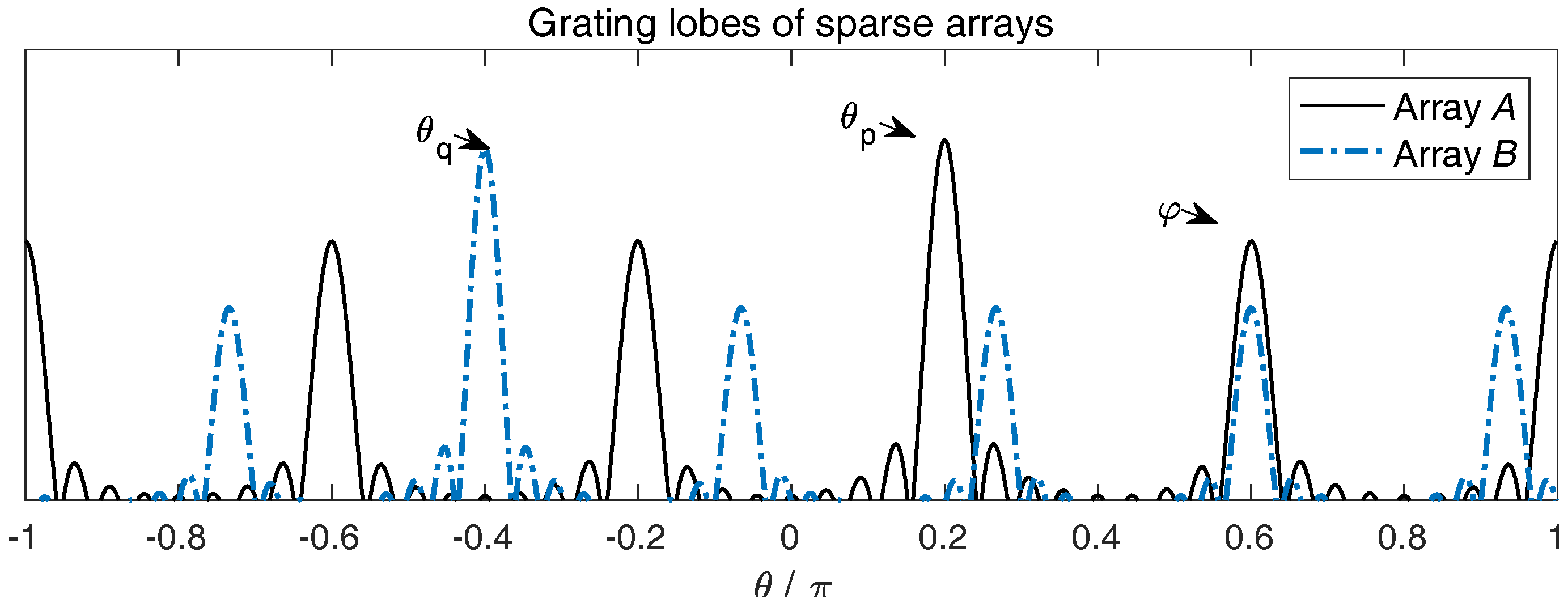
are arbitrary integers. The ambiguity can be illustrated more clearly by the array beam patterns. In
Figure 3, since Array
and
are both sparse and uniform, their beam patterns have multiple grating lobes.
If it happens that a grating lobe of the Array
beam pattern and a grating lobe of the Array
beam pattern overlap at the direction
, i.e., for a pair of non-zero integers
,
the cross-term of the steering vectors becomes
When the smoothed FCM
of Coarray
is eigen-decomposed with the noise subspace projection operator
, the null-spectrum at
becomes
since the cross-term
is in the signal subspace of
. A false peak at
will appear on the pseudo-spectrum.
One remark is in place here. In (
56), the direction
needs not to be strictly equal to
or
. Once a grating lobe of the beam pattern
and a grating lobe of the beam pattern
overlap around
, a false peak still appears.
Furthermore, the grating lobe beamwidths of the beam patterns of and are and , respectively. If and , the beamwidths of the grating lobes are narrower than . From the observation that are coprime numbers, the grating lobes of the beam patterns on Array and on Array may overlap at one direction within at most, which means that the cross-term may produce at most one false peak.
5.2. Supplementary Sparse Array
Suppose that a supplementary sparse array, namely Array
, is deployed with its sensors positioned at
In (
60),
R is an integer, which is respectively coprime to
M and
N, and
is the number of sensors in Array
. Now, Array
and Array
can form a new coprime array, denoted by Coarray
. An FCM
can be derived for the array signal. Dividing Array
into identical subarrays of size
, we can perform the generalized spatial smoothing scheme on
to obtain the smoothed FCM
. Denoting the noise subspace projection operator by
, the null-spectrum of Coarray
is
where
.
If
and
both hold, on the pseudo-spectrum
derived from Coarray
, the cross-term
may produce at most one false peak, denoted by
. The false peak is induced by the following cross-term:
We can derive an important theorem for the position of the false peaks.
Theorem 2. From the same pair of coherent signals , if the cross-term produces a false peak at on the pseudo-spectrum of Coarray , and the cross-term produces a false peak at on the pseudo-spectrum of Coarray , then .
Proof. The proof is by contradiction. On Coarray
, the direction ambiguity indicates the following relations for a pair of non-zero integers
:
If
, combining (
56) and (
63), we can deduce that
. Since
N and
R are coprime numbers,
are within a range such that
are between
, the equation holds only when
, which is contradictory to the non-zero assumption on the integers
. ☐
Theorem 2 indicates that, on two different coprime array configurations, the false peaks created by the same pair of coherent signals do not overlap on the pseudo-spectrum. This property can be used for removing the false peaks.
5.3. Removing False Peaks by Combined Spectrum
To remove the false peaks induced by the direction ambiguity, we use the property for which the false peaks do not overlap. From the three sparse arrays
,
and
, any two sparse arrays constitute a coprime array. Therefore, we may derive three null-spectra:
from Coarray
,
from Coarray
and
from Coarray
. A combined null-spectrum can be generated from the individual null-spectra:
A necessary condition for the existence of a peak at on is that is corresponding to a null at any one of the three null-spectra. In fact, if is the DOA of a true signal, there always exists a null at on any one of the three null-spectra, . However, from Theorem 2, the false peak positions are different. Consequently, the false peaks are removed on the combined pseudo-spectrum on .
7. Conclusions
In this paper, the problem of direction-of-arrival (DOA) estimation of coherent signals on passive coprime arrays is investigated. We resort to the fourth-order cumulants to explore more information about the received signal. Formulating a fourth-order cumulant matrix (FCM) for the signal on a coprime array, a new estimation scheme based on the fourth-order MUSIC algorithm is developed.
The special structure of the FCM is combined with the array configuration to resolve the coherent signals. Using the property that the individual sparse arrays are uniform, on either of the sparse arrays, a series of overlapping identical subarrays can be extracted. Then, taking individually one subarray from each of the sparse arrays, a coprime subarray is constructed. We revealed that the FCMs of any two similar coprime subarrays share the same structure. Analogous to the spatial smoothing scheme applied to the correlation matrix on a uniform linear array, we propose a generalized spatial smoothing scheme applied to the FCM. The scheme yields a smoothed FCM with rank-enhancement. The DOAs of both the independent and coherent signals can be estimated using the smoothed FCM.
To remove the false peaks induced by the direction ambiguity, we use a supplementary sparse array for assistance. On the combined spectrum aided by the supplementary array, the false peaks are removed while the true peaks remain. Simulation examples are given to demonstrate the effectiveness and performance of the proposed approach. Future work includes considering the case of mixed independent, partially correlated and coherent signals. A few simulations were executed to verify the ability of the proposed method to handle this case. However, theoretical guarantees are not provided yet.

