Abstract
In recent years, perovskite solar cells (PSCs) have gained major attention as potentially useful photovoltaic technology due to their ever-increasing power-conversion efficiency (PCE). The efficiency of PSCs depends strongly on the type of materials selected as the electron transport layer (ETL). TiO2 is the most widely used electron transport material for the n-i-p structure of PSCs. Nevertheless, ZnO is a promising candidate owing to its high transparency, suitable energy band structure, and high electron mobility. In this investigation, hybrid mesoporous TiO2/ZnO ETL was fabricated for a perovskite solar cell composed of FTO-coated glass/compact TiO2/mesoporous ETL/FAPbI3/2D perovskite/Spiro-OMeTAD/Au. The influence of ZnO nanostructures with different percentage weight contents on the photovoltaic performance was investigated. It was found that the addition of ZnO had no significant effect on the surface topography, structure, and optical properties of the hybrid mesoporous electron-transport layer but strongly affected the electrical properties of PSCs. The best efficiency rate of 18.24% has been obtained for PSCs with 2 wt.% ZnO.
1. Introduction
Rapid advances in materials technology are creating many novel solutions for energy-efficient applications in solar energy [1,2,3,4,5]. The selection of materials is the foundation of all engineering applications and design. This selection process can be defined by application requirements, possible materials, physical principles, and selection [6,7,8,9]. The intended results of the material selection process lead to the identification of one or more materials with properties that meet the functional requirements of a product. The material selection process is one of the basics of design and engineering [10,11]. The second half of the 20th century brought significant progress in the field of material science, nanotechnology, and materials processing. These developments have led to the production of materials targeted at providing solutions in various key areas, including photovoltaics. Progress in this area is additionally due to the increasing awareness of potential ecological collapse, energy insecurity, and the rising cost of living. Emerging solar-cell technologies that use advanced materials, such as perovskite, dye, metal oxide, organic materials, and quantum dots, are the answer to the challenges of conversion efficiency and longevity [1,12,13].
Since the initial reports on perovskite solar cells (PSCs) with an efficiency of 3.8% in 2009 [14], there has been a rapid increase in reported efficiencies [15,16,17,18,19,20]. The certified stabilized power-conversion efficiency of single-junction perovskite solar cells (PSCs) has reached a value of 26% which is comparable with that of monocrystalline silicon solar cells [21].
Depending on the light incidence, PSCs can be generally divided into either n-i-p (regular) or p-i-n (inverted) geometry [22,23], where [24,25]:
- n refers to n-type—electron transport layer (ETL),
- i refers to the perovskite optical absorption layer,
- p refers to p-type—hole transport layer (HTL).
The electron transport layer (ETL) in PSCs plays an indispensable role in collecting and transporting photogenerated electron carriers and serves as a hole-blocking layer, thus realizing effective charge separation and suppressing charge-carrier recombination. The ETL in PSCs should possess [25,26,27,28,29,30,31]:
- a proper energy-level alignment with the perovskite layer;ETL should have the lowest unoccupied molecular orbital (LUMO) and highest occupied molecular orbital (HOMO), lower than the perovskite active layer. The cascading energy structure ETL can improve electron transport to the cathode, suppress back recombination, and enhance device effectiveness.
- a wide bandgap to ensure good transmittance in the visible light range;
- high electron mobility (>2.5 × 10⁻⁵ cm2 V−1 s−1) for efficient electron transport within the ETL;
- a good photochemical stability.
Moreover, the ETL in n-i-p geometry serves as a nucleation site for the perovskite, which affects the crystal growth and hence the PSC efficiency [32,33].
Many n-type semiconductors, including both organic and inorganic materials, have been employed as ETLs. Organic ETMs (e.g., fullerene or its derivatives, small molecule 3,9-bis(2-methylene-(3-(1,1-dicyanomethylene)-indanone)-5,5,11,11-tetrakis(4-hexylphenyl)-dithieno[2,3-d:2′,3′-d′]-s-indaceno[1,2-b:5,6-b′]-dithiophene (ITIC)) are usually employed in inverted p-i-n PSCs [30,34,35]. In conventional n-i-p structure devices, inorganic ETMs such as TiO2 [36], ZnO [37], SnO2 [38,39], Nb2O5 [40], WO3 [41], BaSnO3 [42], and Zn2SnO4 [33] are more commonly used. Each material has specific benefits to increase the solar cell efficiency. In general, organic materials have lower production costs, but inorganic materials generally have higher thermal and long-term stability [32].
Nowadays, typical PSCs are generally fabricated with a mesoscopic or planar architecture. In a planar architecture, each layer is deposited as a dense, thin film. While in a mesoscopic architecture, perovskite is adsorbed on a mesoporous scaffold. The perovskite grain growth is limited by the pore size of the mesoporous layer, but the thicker perovskite layer provides better light harvesting. If the scaffold layer is involved in the electron transfer, it is referred to as active (e.g., TiO2, ZnO, and SnO2) and named mesoporous electron transport layer; otherwise, it is passive (e.g., SiO2, Al2O3, ZrO2) [43,44,45,46].
TiO2 is the most widely used electron-transport material for the n-i-p structure of PSCs. Titanium dioxide nanostructures play a crucial role in the extraction of photoinduced electrons from the perovskite and then in their transport to the electrode, both as a compact and mesoporous layer. This semiconductive material has a good band alignment with perovskite, which enables faster electron injection from the active layer. Nevertheless, TiO2 suffers from low electron mobility and high defect-state density, which limits the overall device performance [47,48].
A potential n-type semiconducting material is zinc oxide (ZnO) from group II–VI with a band gap energy of 3.37 eV and an exciton binding energy of 60 meV at room temperature [49,50]. Moreover, ZnO has unique chemical and physical properties, such as a good thermal and chemical stability, a high electrochemical coupling coefficient, piezoelectricity, and a broad scope of radiation absorption and high photostability, which provide a wide range of applications in various fields and make it one of the crucial technological materials among all metal oxides. ZnO crystallizes in two main forms, cubic zinc-blende and hexagonal wurtzite (B4). The latter is the most thermodynamically stable crystal structure and the most common in ambient conditions. The zinc-blende form can be stabilized by growing ZnO on substrates with a cubic lattice structure [49,51,52].
Recent studies have shown a variety of ZnO nanostructures, such as nanotetrapods, nanomultipods, nanobelts, nanotubes, nanoparcicles, nano-flowers, nanowires, nanorods, nanoribbons, nanorings, nanoneedles, nanosheets, and shuttle- and comb-like. Over the last few years, scientists have focused on the fabrication and application of one-dimensional (1D) nanostructure materials, such as nanowires and nanorods, because of their fundamental importance and the wide range of potential applications, e.g., in nanodevices [53,54,55].
It is essential to fabricate an electron-transport layer with a suitable composition to improve charge-carrier extraction and transportation for achieving a higher efficiency of solar cells. In this study, we introduce the ZnO nanopowder, consisting of various shape nanostructures, to a TiO2 solution for the fabrication of the mesoporous electron transport layer of PSCs. The regular (n-i-p) mesoscopic architectures of perovskite solar cells were studied. In order to produce the mesoporous hybrid TiO2/ZnO-layer precursor was prepared by dissolving TiO2 paste in ethanol. Then, contents of different weights of ZnO nanostructures (0, 1, 2, 3, 4 and 8 wt.%) were added to the TiO2 solution. The prepared mesoporous ETLs were characterized by scanning electron microscopy, atomic force microscopy, X-ray diffraction, and UV-Vis spectroscopy. The effects of using ZnO nanostructures with various shapes and dimensions on the electrical properties of PSCs were also investigated.
2. Technology of Perovskite Solar Cells
In the present study, we investigated the perovskite solar cell in a structure of FTO/compact TiO2 (c TiO2)/mesoporous TiO2 (mp-TiO2) with the addition of ZnO nanostructures/FAPbI3/2D perovskite/Spiro-OMeTAD/Au. The perovskite devices were prepared according to the procedure developed in the Institute of Metallurgy and Materials Science of the Polish Academy of Sciences. Fluorine-doped tin-oxide-coated glass was ultrasonically cleaned sequentially in an aqueous solution of 2% Hellmanex, deionized water, isopropanol for 5 min in each solvent, and then dried. The TiO2 dense layer have been deposited from tetraethyl orthotitanate, dissolved in a mixture of ethanol and hydrochloric acid, using spin-coating method. Then, the TiO2 thin film was dried at 200 °C and heated at 500 °C. In order to produce the mesoporous layer, a TiO2 precursor solution was prepared by dissolving 30 NR-D paste in ethanol. Different weight contents of ZnO nanostructures (x = 0, 1, 2, 3, 4 and 8 wt.% to weight of TiO2) were added to the TiO2 solution. The spin-coating method was used to create the mesoporous layer of TiO2/ZnO. The samples were dried at 200 °C and heated at 500 °C.
The FAPbI3 perovskite precursor was produced in a glovebox filled with nitrogen. The precursor solution was developed by mixing lead iodide (PbI2), formamidinium iodide (FAI) and methylammonium chloride (MACl) in a co-solvent of DMF/DMSO (4:1 v/v). The FAPbI3 perovskite layer was deposited using the anti-solvent method with ethyl acetate. The prepared perovskite precursor solution was deposited on the meso-TiO2/ZnO-coated substrate at 8000 rpm (with an acceleration of 2000 rpm). Diethyl ether was dropped onto the substrate during the 10th s of the spin-coating. The perovskite film layer was annealed at 150 °C for 10 min. to allow the formation of a black phase FAPbI3. To fabricate a 2D perovskite, 0.04 M octylammonium iodide (OAI) solution was prepared by dissolving OAI in IPA. OAI solution was deposited on the perovskite substrate by spin-coating at 3000 rpm for 15 s, and then the substrate was heated at 100 °C.
Spiro-OMeTAD was used as the hole transport layer (HTL) material. Spiro-OMeTAD was dissolved in chlorobenzene and mixed with LiTFSI solution (prepared by dissolving LiTFSI in acetonitrile) and 4-tert-butylpyridine (tBP). Spiro-OMeTAD solution was spin-coated on the perovskite layer at 2000 rpm for 30 s. After that, the samples were taken out of the glove box, masked, and coated with gold by thermal evaporation. Au electrodes had a surface of 0.25 cm2 and a thickness of approximately 80 nm.
3. Results and Discussion
Figure 1 presents the morphology of the ZnO nanopowder used to fabricate the hybrid TiO2/ZnO mesoporous electron-transport layer. The ZnO nanopowder consists of nanostructures of various shapes, including nanoparticles and nanorods/nanowires (Figure 1b–e). The EDS analysis of the chemical composition certified the purity of the ZnO nanopowder and showed the presence of the two elements zinc and oxygen. The applied ZnO material is described in detail in the manuscripts [50,54,55,56,57]. The XRD analysis carried out for the nanopowder showed the existance of sharp crystalline peaks for 2θ angles: 37.1°, 40.2°, 42.4°, 55.8°, 66.8°, 74.6°,80.9° and 82.4° originating from Miller indices: (010), (002), (011), (012), (110), (013), (112) and (021), respectively. These peaks indicate the existance of hexagonal ZnO phase characteristzed by the P63mc space group (ICDD PDF4+ 98-018-5827) [54]. In addition, electron diffraction on a selected area (SAED) was carried out using a transmission electron microscope, which confirmed the results of the study of the structure of the ZnO nanopowder obtained using XRD and showed that the examined nanostructures were single crystals [54]. The analysis of the morphology of the tested ZnO semiconductor nanopowder, based on the recorded TEM and SEM images, showed the spherical and oblong shape of the tested nanostructures, where their diameters ranged from about 50 nm to 350 nm, and lengths reached about 500 nm [50,54,55]. Studies of the optical properties of the ZnO nanostructures employed were made using UV-Vis spectroscopy. Analysis of the absorption spectrum as a function of the wavelength showed a sharp absorption edge-fall at 360 nm wavelength, while the absorption maximum fell at 340 nm wavelength, which is confirmed with the results obtained for pure one-dimensional ZnO nanostructures shown in [56]. The energy gap (Eg) analysis based on the obtained UV-Vis spectrum showed that the investigated ZnO nanostructures were characterized by an Eg value of about 3.2 eV [57].
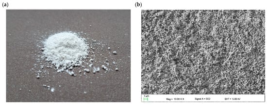
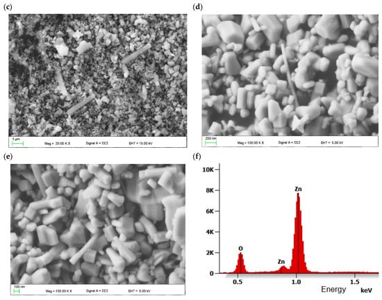
Figure 1.
Morphology of ZnO nanopowder: (a) macroscopic image (b–e) SEM images and (f) EDS analysis of the chemical composition.
Figure 2 shows SEM topography of the spin-coated TiO2 layer with and without the addition of ZnO nanostructures. A highly porous structure without cracks and gaps can be observed. The metal oxide nanostructures form agglomerates. It was found that the addition of ZnO up to 8 wt.% does not influence the mesoporous ETL surface topography.
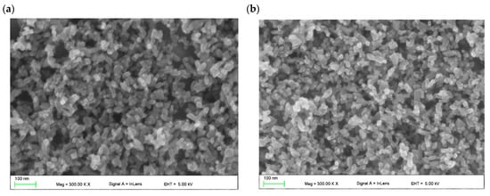
Figure 2.
Topography of spin-coated mesoporous TiO2 layer (a) without and (b) with 8 wt.% addition of ZnO nanostructures.
The surface topography of a deposited hybrid TiO2/ZnO layer was also studied using an atomic-force microscope in non-contact mode (Figure 3). A quantitative representation of the surface topography of the pure mesoporous TiO2 layer with the addition of ZnO nanostructures is represented by the roughness coefficients: root mean square (RMS) and the average arithmetic deviation of the profile from the average line (Ra) (Table 1).
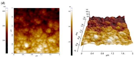
Figure 3.
2D and 3D AFM images of mesoporous TiO2 layer (a) without and (b) with 2% (c) with 4% (d) with 8% addition of ZnO nanostructures.

Table 1.
Comparison of roughness values of mesoporous TiO2 layer without and with addition of ZnO nanostructures.
The mesoporous TiO2 layer is reflected in the relatively high RMS and Ra values. The AFM images clearly indicate a structure composed of nanoparticles and its agglomerates with a size above 100 nm, forming three-dimensional complex structures with a high specific surface area. The large specific surface area, in turn, plays an important role in the penetration of the perovskite solar-radiation absorber, and thus improves the efficiency of the final solar cell.
It can be seen that the share of nanostructural ZnO nanoadditives does not significantly affect the surface area of the layers obtained in the case of 1–4% share. It can be noticed that the layer with the highest content of ZnO nanoaddition shows significantly higher values of Ra and RMS coefficients, which may improve the charge transport in the perovskite device.
It was found that the hybrid mesoporous TiO2/ZnO electron-transport layer with extreme ZnO content (1% and 8% ZnO) and one with intermediate content (3% ZnO) selected for testing are characterized by identical diffraction patterns. This proves the lack of structural differences in the tested layers. Example diffraction patterns obtained for three samples with different compositions at different GIXD angles are shown in Figure 4. The top layer (α = 0.1°) does not differ from the layers tested at the angle α = 0.1°, which indicates the lack of additional oxide layers that could be formed due to the atmosphere on the material’s surface.
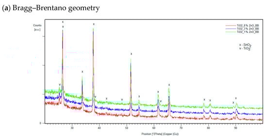
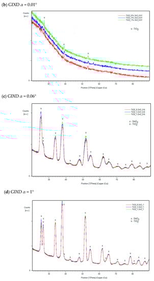
Figure 4.
Examples of diffraction patterns of manufactured layers with the weight content of 1%, 3% and 8% ZnO for measurements in the Bragg–Brentano geometry (a) and at the GIXD angles α = 0.01° (b), α = 0.6° (c) and α = 1° (d).
Figure 5 presents the transmittance plot of tested mesoporous titanium oxide layers with the addition of zinc oxide nanostructures in 0%, 1%, 2%, 3%, 4% and 8% deposited on FTO glass with 70 nm-thick blocking TiO2. It was found that the incorporation of ZnO nanostructures into the mesoporous TiO2 layer does not significantly affect light transmission. All produced layers show a transmittance above 60% for wavelengths in the range of 366–900 nm. It was observed that for higher contents of ZnO (2%, 4% and 8%), for the wavelength below 500 nm, there is a peak shift. This may indicate an increase in the thickness of the spin-coated layers. The Tauc plot method was used to determine the band-gap energy of manufactured films. The absorption coefficient (α) was calculated from the formula: α = −(ln(T/(1 − R))/d where: d—thickness of the tested layer, T—transmission at a given wavelength, R—reflection coefficient. In the Tauc plot, the direct optical band gap can be determined from the intercept of the leading-edge linear extrapolation with hν axis, as displayed by lines in Figure 6. The calculated Eg is around 3.78 eV for all tested samples. This response is dominated by FTO or glass substrate, but no important differences were visible for any ZnO addition layers. The analysis of transmittance spectra and extracted optical band gaps suggests that the addition of ZnO nanostructures to the mesoporous TiO2 does not worsen the optical properties but might even be slightly beneficial. It confirms that a hybrid TiO2/ZnO layer is a promising candidate as the mesoporous ETL, owing to its high transparency and appropriate band gap that is well fitted into the energy structure of the perovskite solar cell.
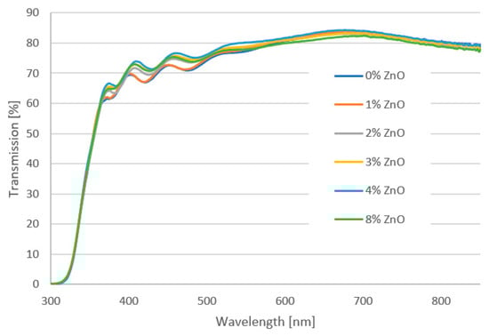
Figure 5.
UV-Vis transmission spectra of the hybrid mesoporous TiO2/ZnO layer with different addition of ZnO nanostructures.
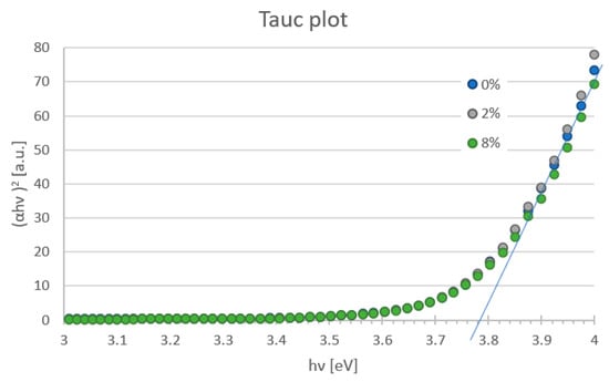
Figure 6.
Band gap energy of the mesoporous TiO2 layer with different addition of ZnO nanostructures estimated from Tauc plot.
The measurement of the current-voltage (J-V) characteristics is the most important step for quality control and optimization of the fabrication process in research and industrial production of solar cells. A comparison of the J-V characteristics of the PSCs with a hybrid mesoporous TiO2/ZnO layer is shown in Figure 7. The electrical properties such as power conversion efficiency (PCE), fill factor (FF), short-circuit current density (Jsc) and open-circuit voltage (Voc) of fabricated PSCs are summarized in Table 2. In this study, four series of perovskite solar cells were fabricated. After the first series, PSCs with an ETL layer containing 8% ZnO were abandoned due to a significant decrease in efficiency.
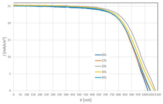
Figure 7.
Average current-voltage characteristics of perovskite solar cells based on hybrid mesoporous TiO2/ZnO layer with a different addition of ZnO nanostructures.
Table 2.
Average electrical parameters and their standard deviation for perovskite solar cells based on hybrid mesoporous TiO2/ZnO layer with different addition of ZnO nanostructures.
It was found that the incorporation of ZnO nanostructures into the mesoporous TiO2 layer has a major impact on the efficiency of PSCs. The highest efficiency of 18.24% demonstrated solar cells with the addition of 2% ZnO, which increased by 1.13% compared to devices with pure TiO2 mesoporous layer. The obtained research results indicate that the efficiency of PSCs is mainly determined by the open-circuit voltage. The addition of ZnO can result in better band alignment with perovskite, which makes it possible for faster electron injection from the active layer. The highest fill factor of 0.67 was obtained for PSCs with pure TiO2 and with the addition of 2% ZnO nanostructures. The short-circuit current density rises slightly (by 0.3 mA/cm2) with an increasing amount of ZnO addition to 2% from 25.09 (without ZnO) to 25.39 mA/cm2 (2% ZnO). This may indicate that the formation of local TiO2-ZnO heterostructures promotes faster electron transport and increases the number of carriers. Despite the significant improvement in efficiency by the addition of ZnO, it was noted that its excessive concentration deteriorated the photovoltaic performance of PSCs. This may be because higher ZnO concentration increases the resistance to the electron transport and charge transition, which promotes the charge-recombination process.
As we have mentioned earlier, four series of perovskite solar cells were prepared. Figure 8 presents the repeatability and reproducibility analysis of manufactured perovskite solar cells by means of box and whisker plots. It was observed that the highest repeatability of FF and efficiency were found for the PSC with 1% and 3% ZnO, respectively. Solar cells with the addition of 3 and 4% ZnO seem to show a significant dispersion in the obtained short-circuit current density compared to other devices. However, the standard deviation for them does not exceed 1.99%. Moreover, the close distribution of the Jsc and Voc (<2.42%) may also indirectly indicate the homogeneity of the deposited layer. The values of the electrical properties of the devices showed only a slight deviation from the average, which proves the high repeatability of the produced PSCs.
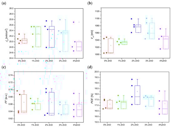
Figure 8.
Box and whisker plots for electrical properties of prepared PSCs based on a hybrid mesoporous TiO2/ZnO layer with different addition of ZnO nanostructures (a) Jsc, (b) Voc, (c) FF, (d) PCE.
4. Materials and Methods
Ultra-pure lead iodide beads were purchased from Alfa Aesar. Formamidinium iodide and methylammonium chloride were purchased from Greatcell Solar Ltd. (Queanbeyan, Australia). Spiro OMeTAD(N2,N2,N2′,N2′,N7,N7,N7′,N7′-octakis(4-methoxyphenyl)-9,9′-spirobi[9H-fluorene]-2,2′,7,7′-tetramine), ultra-dry dimethylformamide (DMF), ultra-dry dimethyl sulfoxide (DMSO) and ultra-dry chlorobenzene (CB), dry isopropanol (IPA), 4-tert-butyl pyridine, and lithium bistrifluorosulfonylimide (LiTFSI) were purchased from Sigma Aldrich. All the chemicals were used as received without additional purification. Fluorine-doped tin oxide (FTO)-coated glass (8 Ω/sq) and titanium dioxide paste (30 NR-D) were purchased from Greatcell Solar Ltd. (Queanbeyan, Australia). The applied ZnO nanopowder is described in detail in the manuscripts [50,54,55,56,57], but in this paper the morphology of the ZnO nanopowders and their chemical composition and the topography of the hybrid TiO2/ZnO layer were examined using the Supra 35 scanning electron microscope (SEM) from Carl Zeiss (Jena, Germany), equipped with an EDS detector. The surface topography of the spin-coated electron transport layer was investigated using an atomic force microscope (AFM) (Park Systems XE 100 with dedicated XEI Software 5.2.4 Build 1 (Suwon, Republic of Korea) in non-contact mode.
X-ray measurements of selected samples containing 1%, 3% and 8% (weight) of ZnO were performed on a PANalytical Empyrean Diffractometer (Malvern, UK), using copper radiation (Cu Kα = 1.5418 Å) and a PIXcell counter. The diffraction patterns of each sample were measured in the Bragg–Brentano geometry (as a reference, substrate measurement) and in the Grazing Incident X-ray Diffraction geometry for different angles of incidence of the X-ray beam for the analysis of individual layers. The effective penetration depth was estimated on the basis of the following formula:
where:
z—effective penetration depth,
µ—sum of linear X-ray absorption coefficients of chemical compounds present in the tested material,
α—angle of incidence of the X-ray beam,
2θ—angle at which the diffraction peak was recorded, taking into account the copper radiation, the appropriate angle of incidence of the radiation, the absorption coefficients of the components of the layers (Table 3). Estimated radiation-penetration depths may differ from the actual ones due to the porosity of the material, heterogeneity of layers, and local differences in material density. For this reason, measurements were made for a number of angles, not limited to the expected layer thicknesses.
Table 3.
Measurement condition in GIXD.
A Lambda 950 S UV-Vis spectrophotometer from Perkin Elmer (Waltham, MA, USA) was used to determine the optical properties of the manufactured hybrid TiO2/ZnO electron-transport layers in the wavelength range of 300–900 nm. The electrical parameters of manufactured perovskite solar cells with a hybrid mesoporous TiO2/ZnO electron transport layer were characterized by measurements of current-voltage (I–V) characteristics using PV Test Solutions Tadeusz Zdanowicz Solar Cell I-V Tracer System (Wroclaw, Poland), Keithley 2400 source meter (Cleveland, OH, USA), Photo Emission Tech (Ventura, CA, USA) AAA class solar simulator under standard AM 1.5 radiation and light intensity 1000 W/m2.
5. Conclusions
Due to growing energy consumption, uncertainty about its supply, and the limited resources of fossil fuel, it is becoming necessary to convert energy from renewable sources. Solar power is an important resource because of its inexhaustibility and pollution-free character. Moreover, solar energy is the cleanest and most abundant renewable energy source available in the world. The answer to these challenges lies in solar cells that directly convert solar energy into electricity. Perovskite solar cells have attracted tremendous attention thanks to their good stability and rising power-conversion efficiency.
In this paper, TiO2 nanoparticles with the addition of various ZnO nanostructure, including nanoparticles and one-dimensional nanoadditives such as nanorods and nanowires, were proposed as a hybrid mesoporous electron transport layer of PSCs. The introduction of ZnO nanostructures with various shapes and dimensions into the mesoporous TiO2 layer does not negatively affect its transparency. X-ray diffraction analysis does not reveal a change in the structure of layers with the addition of ZnO nanopowder (1, 3, 8 wt.%). The highest efficiency of 18.24% was obtained for perovskite solar cells with the addition of 2 wt.% ZnO, which is 1.13% higher compared to devices without ZnO nanostructures. This is probably due to the higher electron mobility compared to the TiO2 material and the smooth path for electron transport in one-dimensional structures. The addition of ZnO can result in better band alignment with perovskite, which makes it possible for faster electron injection from the active layer. The statistical analysis showed good reproducibility and repeatability of the photovoltaic parameters of the manufactured devices. These results indicate that the ZnO/TiO2 composite has demonstrated to be a promising candidate as a mesoporous electron transport layer for high-performance mesoscopic perovskite solar cells.
Author Contributions
Conceptualization, A.D.; methodology, A.D., Z.S., K.G.-N. and M.K.; validation, M.L., W.M., E.T., P.P. and T.T.; formal analysis, A.D., Z.S., K.G.-N., M.K. and P.J.; investigation, A.D., Z.S., K.G.-N., M.K. and P.J.; data curation, A.D.; writing—original draft preparation, A.D.; writing—review and editing, M.L., E.T. and P.P.; supervision, T.T. All authors have read and agreed to the published version of the manuscript.
Funding
This publication was supported under the Initiative of Excellence—Research University program implemented at the Silesian University of Technology, Poland, 2021–2023. The experiments were executed with the cooperation of M. Lipiński et al. from the Photovoltaic Laboratory of the Institute of Metallurgy and Materials Science of the Polish Academy of Sciences within the statutory work Z-2/2023 and grant no. 2018/31/B/ST8/03294 supported by the National Science Centre of Poland.
Institutional Review Board Statement
Not applicable.
Informed Consent Statement
Not applicable.
Data Availability Statement
Not applicable.
Conflicts of Interest
The authors declare no conflict of interest.
Sample Availability
Not applicable.
References
- Sanglee, K.; Nukunudompanich, M.; Part, F.; Zafiu, C.; Bello, G.; Ehmoser, E.-K.; Chuangchote, S. The current state of the art in internal additive materials and quantum dots for improving efficiency and stability against humidity in perovskite solar cells. Heliyon 2022, 8, e11878. [Google Scholar] [CrossRef]
- Drygała, A.; Dobrzański, L.A.; Szindler, M.; Prokopowicz, M.P.V.; Pawlyta, M.; Lukaszkowicz, K. Carbon Nanotubes Counter Electrode for Dye-Sensitized Solar Cells Application. Arch. Met. Mater. 2016, 61, 803–806. [Google Scholar] [CrossRef]
- Lipiński, M.; Socha, R.; Kędra, A.; Gawlińska, K.; Kulesza-Matlak, G.; Major, Ł.; Drabczyk, K.; Łaba, K.; Starowicz, Z.; Gwóźdź, K.; et al. Studying of Perovskite Nanoparticles in PMMA Matrix Used As Light Converter for Silicon Solar Cell. Arch. Met. Mater. 2017, 62, 1733–1739. [Google Scholar] [CrossRef]
- Dobrzański, L.A.; Drygała, A. Influence of Laser Processing on Polycrystalline Silicon Surface. Mater. Sci. Forum 2012, 706–709, 829–834. [Google Scholar] [CrossRef]
- Smok, W.; Tański, T.; Drygała, A.; Podwórny, J. Facile route to prepare hybrid TiO2-SnO2 DSSCs. Appl. Surf. Sci. 2022, 605, 154850. [Google Scholar] [CrossRef]
- Bayda, S.; Adeel, M.; Tuccinardi, T.; Cordani, M.; Rizzolio, F. The History of Nanoscience and Nanotechnology: From Chemical–Physical Applications to Nanomedicine. Molecules 2020, 25, 112. [Google Scholar] [CrossRef] [PubMed]
- Szewieczek, D.; Tyrlik-Held, J.; Lesz, S. Changes of mechanical properties and fracture morphology of amorphous tapes involved by heat treatment. J. Mater. Process. Technol. 2001, 109, 190–195. [Google Scholar] [CrossRef]
- Drygała, A. Influence of TiO2 film thickness on photovoltaic properties of dye-sensitized solar cells. IOP Conf. Ser. Earth Environ. Sci. 2021, 642, 012001. [Google Scholar] [CrossRef]
- Lesz, S.; Kremzer, M.; Gołombek, K.; Nowosielski, R. Influence of milling time on amorphization of Mg–Zn–Ca powders synthesized by mechanical alloying technique. Arch. Met. Mater. 2018, 63, 845–851. [Google Scholar] [CrossRef]
- Malik, S.; Muhammad, K.; Waheed, Y. Nanotechnology: A Revolution in Modern Industry. Molecules 2023, 28, 661. [Google Scholar] [CrossRef]
- Kremzer, M. Ceramic porous preforms manufactured from waste materials. Arch. Met. Mater. 2022, 67, 283–288. [Google Scholar] [CrossRef]
- Wibowo, A.; Marsudi, M.A.; Amal, M.I.; Ananda, M.B.; Stephanie, R.; Ardy, H.; Diguna, L.J. ZnO nanostructured materials for emerging solar cell applications. RSC Adv. 2020, 10, 42838–42859. [Google Scholar] [CrossRef] [PubMed]
- Drygała, A.; Szindler, M.; Szindler, M.; Jonda, E. Atomic layer deposition of TiO2 blocking layers for dye-sensitized solar cells. Microelectron. Int. 2020, 37, 87–93. [Google Scholar] [CrossRef]
- Kojima, A.; Teshima, K.; Shirai, Y.; Miyasaka, T. Organometal Halide Perovskites as Visible-Light Sensitizers for Photovoltaic Cells. J. Am. Chem. Soc. 2009, 131, 6050–6051. [Google Scholar] [CrossRef] [PubMed]
- Green, M.A.; Dunlop, E.D.; Siefer, G.; Yoshita, M.; Kopidakis, N.; Bothe, K.; Hao, X. Solar cell efficiency tables (Version 61). Prog. Photovolt. Res. Appl. 2022, 31, 3–16. [Google Scholar] [CrossRef]
- Tai, Q.; Tang, K.-C.; Yan, F. Recent progress of inorganic perovskite solar cells. Energy Environ. Sci. 2019, 12, 2375–2405. [Google Scholar] [CrossRef]
- Wang, Q.; Tang, W.; Chen, Y.; Qiu, W.; Wu, Y.; Peng, Q. Over 25% efficiency and stable bromine-free RbCsFAMA-based quadruple cation perovskite solar cells enabled by an aromatic zwitterion. J. Mater. Chem. A 2023, 11, 1170–1179. [Google Scholar] [CrossRef]
- Min, H.; Lee, D.Y.; Kim, J.; Kim, G.; Lee, K.S.; Kim, J.; Paik, M.J.; Kim, Y.K.; Kim, K.S.; Kim, M.G.; et al. Perovskite solar cells with atomically coherent interlayers on SnO2 electrodes. Nature 2021, 598, 444–450. [Google Scholar] [CrossRef]
- Xiao, H.; Zuo, C.; Zhang, L.; Zhang, W.; Hao, F.; Yi, C.; Liu, F.; Jin, H.; Ding, L. Efficient inorganic perovskite solar cells made by drop-coating in ambient air. Nano Energy 2023, 106, 108061. [Google Scholar] [CrossRef]
- Liu, L.; Xiao, Z.; Zuo, C.; Ding, L. Inorganic perovskite/organic tandem solar cells with efficiency over 20%. J. Semicond. 2021, 42, 020501. [Google Scholar] [CrossRef]
- NREL. Best Research-Cell Efficiency Chart. Available online: https://www.nrel.gov/pv/cell-efficiency.html (accessed on 30 May 2023).
- Príncipe, J.; Duarte, V.C.M.; Andrade, L. Inverted Perovskite Solar Cells: The Emergence of a Highly Stable and Efficient Architecture. Energy Technol. 2021, 10, 2100952. [Google Scholar] [CrossRef]
- Yu, W.; Zou, Y.; Zhang, S.; Liu, Z.; Wu, C.; Qu, B.; Chen, Z.; Xiao, L. Carbon-based perovskite solar cells with electron and hole-transporting/-blocking layers. Mater. Futures 2023, 2, 022101. [Google Scholar] [CrossRef]
- Zhao, X.; Wang, M. Organic hole-transporting materials for efficient perovskite solar cells. Mater. Today Energy 2018, 7, 208–220. [Google Scholar] [CrossRef]
- Pan, H.; Zhao, X.; Gong, X.; Li, H.; Ladi, N.H.; Zhang, X.L.; Huang, W.; Ahmad, S.; Ding, L.; Shen, Y.; et al. Advances in design engineering and merits of electron transporting layers in perovskite solar cells. Mater. Horiz. 2020, 7, 2276–2291. [Google Scholar] [CrossRef]
- Jiménez-López, J.; Cambarau, W.; Cabau, L.; Palomares, E. Charge Injection, Carriers Recombination and HOMO Energy Level Relationship in Perovskite Solar Cells. Sci. Rep. 2017, 7, 6101. [Google Scholar] [CrossRef] [PubMed]
- Mahmood, K.; Sarwar, S.; Mehran, M.T. Current status of electron transport layers in perovskite solar cells: Materials and properties. RSC Adv. 2017, 7, 17044–17062. [Google Scholar] [CrossRef]
- Dkhili, M.; Lucarelli, G.; De Rossi, F.; Taheri, B.; Hammedi, K.; Ezzaouia, H.; Brunetti, F.; Brown, T.M. Attributes of High-Performance Electron Transport Layers for Perovskite Solar Cells on Flexible PET versus on Glass. ACS Appl. Energy Mater. 2022, 5, 4096–4107. [Google Scholar] [CrossRef]
- Hong, S.; Lee, J. Recent Advances and Challenges toward Efficient Perovskite/Organic Integrated Solar Cells. Energies 2023, 16, 266. [Google Scholar] [CrossRef]
- Kumar, A.; Ojha, S.K.; Vyas, N.; Ojha, A.K. Designing Organic Electron Transport Materials for Stable and Efficient Performance of Perovskite Solar Cells: A Theoretical Study. ACS Omega 2021, 6, 7086–7093. [Google Scholar] [CrossRef]
- Shin, S.S.; Lee, S.J.; Seok, S.I. Exploring wide bandgap metal oxides for perovskite solar cells. APL Mater. 2019, 7, 022401. [Google Scholar] [CrossRef]
- Lin, L.; Jones, T.W.; Yang, T.C.; Duffy, N.W.; Li, J.; Zhao, L.; Chi, B.; Wang, X.; Wilson, G.J. Inorganic Electron Transport Materials in Perovskite Solar Cells. Adv. Funct. Mater. 2020, 31, 2008300. [Google Scholar] [CrossRef]
- Wu, W.-Q.; Chen, D.; Li, F.; Cheng, Y.-B.; Caruso, R.A. Solution-processed Zn2SnO4 electron transporting layer for efficient planar perovskite solar cells. Mater. Today Energy 2018, 7, 260–266. [Google Scholar] [CrossRef]
- Wang, D.; Ye, T.; Zhang, Y. Recent advances of non-fullerene organic electron transport materials in perovskite solar cells. J. Mater. Chem. A 2020, 8, 20819–20848. [Google Scholar] [CrossRef]
- Choi, D.-S.; Kwon, S.-N.; Na, S.-I. Non-Fullerene Small Molecule Electron-Transporting Materials for Efficient p-i-n Perovskite Solar Cells. Nanomaterials 2020, 10, 1082. [Google Scholar] [CrossRef] [PubMed]
- Sławek, A.; Starowicz, Z.; Lipiński, M. The Influence of the Thickness of Compact TiO2 Electron Transport Layer on the Performance of Planar CH3NH3PbI3 Perovskite Solar Cells. Materials 2021, 14, 3295. [Google Scholar] [CrossRef] [PubMed]
- Han, J.; Kwon, H.; Kim, E.; Kim, D.-W.; Son, H.J. Interfacial engineering of a ZnO electron transporting layer using self-assembled monolayers for high performance and stable perovskite solar cells. J. Mater. Chem. A 2020, 8, 2105–2113. [Google Scholar] [CrossRef]
- Eliwi, A.A.; Byranvand, M.M.; Fassl, P.; Khan, M.R.; Hossain, I.M.; Frericks, M.; Ternes, S.; Abzieher, T.; Schwenzer, J.A.; Mayer, T.; et al. Optimization of SnO2 electron transport layer for efficient planar perovskite solar cells with very low hysteresis. Mater. Adv. 2022, 3, 456–466. [Google Scholar] [CrossRef]
- Kim, J.; Kim, K.S.; Myung, C.W. Efficient electron extraction of SnO2 electron transport layer for lead halide perovskite solar cell. Comput. Mater. 2020, 6, 100. [Google Scholar] [CrossRef]
- Feng, J.; Yang, Z.; Yang, D.; Ren, X.; Zhu, X.; Jin, Z.; Zi, W.; Wei, Q.; Liu, S. E-beam evaporated Nb2O5 as an effective electron transport layer for large flexible perovskite solar cells. Nano Energy 2017, 36, 1–8. [Google Scholar] [CrossRef]
- Ali, F.; Pham, N.D.; Fan, L.; Tiong, V.; Dai, X.; Bell, J.M.; Wang, H.; Tesfamichael, T. Low Hysteresis Perovskite Solar Cells Using an Electron-Beam Evaporated WO3–x Thin Film as the Electron Transport Layer. ACS Appl. Energy Mater. 2019, 2, 5456–5464. [Google Scholar] [CrossRef]
- Sun, C.; Guan, L.; Guo, Y.; Fang, B.; Yang, J.; Duan, H.; Chen, Y.; Li, H.; Liu, H. Ternary oxide BaSnO3 nanoparticles as an efficient electron-transporting layer for planar perovskite solar cells. J. Alloys Compd. 2017, 772, 196–206. [Google Scholar] [CrossRef]
- Pascoe, A.R.; Yang, M.; Kopidakis, N.; Zhu, K.; Reese, M.O.; Rumbles, G.; Fekete, M.; Duffy, N.W.; Cheng, Y.-B. Planar versus mesoscopic perovskite microstructures: The influence of CH3NH3PbI3 morphology on charge transport and recombination dynamics. Nano Energy 2016, 36, 439–452. [Google Scholar] [CrossRef]
- Tooghi, A.; Fathi, D.; Eskandari, M. High-performance perovskite solar cell using photonic–plasmonic nanostructure. Sci. Rep. 2020, 10, 11248. [Google Scholar] [CrossRef] [PubMed]
- Du, T.; Xu, W.; Xu, S.; Ratnasingham, S.R.; Lin, C.-T.; Kim, J.; Briscoe, J.; McLachlan, M.A.; Durrant, J.R. Light-intensity and thickness dependent efficiency of planar perovskite solar cells: Charge recombination versus extraction. J. Mater. Chem. C 2020, 8, 12648–12655. [Google Scholar] [CrossRef]
- Yenel, E.; Kus, M. A novel natural scaffold layer improving efficiency, stability and reproducibility of Perovskite solar cells. Sci. Rep. 2023, 13, 4319. [Google Scholar] [CrossRef] [PubMed]
- Qureshi, A.A.; Javed, H.M.A.; Javed, S.; Bashir, A.; Usman, M.; Akram, A.; Ahmad, M.I.; Ali, U.; Shahid, M.; Rizwan, M.; et al. Incorporation of Zr-doped TiO2 nanoparticles in electron transport layer for efficient planar perovskite solar cells. Surf. Interfaces 2021, 25, 101299. [Google Scholar] [CrossRef]
- Garcia, V.J.; Pelicano, C.M.; Yanagi, H. Low temperature-processed ZnO nanorods-TiO2 nanoparticles composite as electron transporting layer for perovskite solar cells. Thin Solid Films 2018, 662, 70–75. [Google Scholar] [CrossRef]
- Gawlińska-Nęcek, K.; Wlazło, M.; Socha, R.; Stefaniuk, I.; Major, Ł.; Panek, P. Influence of Conditioning Temperature on Defects in the Double Al2O3/ZnO Layer Deposited by the ALD Method. Materials 2021, 14, 1038. [Google Scholar] [CrossRef]
- Matysiak, W.; Tański, T.; Zaborowska, M. Manufacturing process and characterization of electrospun PVP/ZnO NPs nanofibers. Bull. Pol. Acad. Sci. Tech. Sci. 2019, 67, 193–200. [Google Scholar] [CrossRef]
- Raha, S. Ahmaruzzaman ZnO nanostructured materials and their potential applications: Progress, challenges and perspectives. Nanoscale Adv. 2022, 4, 1868–1925. [Google Scholar] [CrossRef]
- Yang, D.; Gopal, R.A.; Lkhagvaa, T.; Choi, D. Oxidizing agent impacting on growth of ZnO tetrapod nanostructures and its characterization. Environ. Res. 2021, 197, 111032. [Google Scholar] [CrossRef] [PubMed]
- Schmidt-Mende, L.; MacManus-Driscoll, J.L. ZnO–nanostructures, defects, and devices. Mater. Today 2007, 10, 40–48. [Google Scholar] [CrossRef]
- Matysiak, W.; Tański, T. Novel bimodal ZnO (amorphous)/ZnO NPs (crystalline) electrospun 1D nanostructure and their optical characteristic. Appl. Surf. Sci. 2019, 474, 232–242. [Google Scholar] [CrossRef]
- Matysiak, W.; Zaborowska, M. Hybrid ZnO/ZnO-NPs nanofibres fabricated via electrospinning. J. Achiev. Mater. Manuf. Eng. 2019, 94, 5–12. [Google Scholar] [CrossRef]
- Matysiak, W.; Tański, T.; Zaborowska, M. Manufacturing process, characterization and optical investigation of amorphous 1D zinc oxide nanostructures. Appl. Surf. Sci. 2018, 442, 382–389. [Google Scholar] [CrossRef]
- Matysiak, W.; Tański, T.; Zaborowska, M. Analysis of the Optical Properties of PVP/ZnO Composite Nanofibers. In Properties and Characterization of Modern Materials; Öchsner, A., Altenbach, H., Eds.; Springer: Singapore, 2017; Volume 33, pp. 43–49. [Google Scholar] [CrossRef]
Disclaimer/Publisher’s Note: The statements, opinions and data contained in all publications are solely those of the individual author(s) and contributor(s) and not of MDPI and/or the editor(s). MDPI and/or the editor(s) disclaim responsibility for any injury to people or property resulting from any ideas, methods, instructions or products referred to in the content. |
© 2023 by the authors. Licensee MDPI, Basel, Switzerland. This article is an open access article distributed under the terms and conditions of the Creative Commons Attribution (CC BY) license (https://creativecommons.org/licenses/by/4.0/).