Abstract
The exothermic reactor for ammonia synthesis is a primary device determining the performance of the energy storage system. The Braun-type ammonia synthesis reactor is used as the exothermic reactor to improve the heat release rate. Due to the entirely different usage scenarios and design objectives, its parameters need to be redesigned and optimized. Based on finite-time thermodynamics, a one-dimensional model is established to analyze the effects of inlet gas molar flow rate, hydrogen–nitrogen ratio, reactor length and inlet temperature on the total entropy generation rate and the total exothermic rate of the reactor. It’s found that the total exothermic rate mainly depends on the inlet molar flow rate. Furthermore, considering the minimum total entropy generation rate and maximum total exothermic rate, the NSGA-II algorithm is applied to optimize seven reactor parameters including the inlet molar flow rate, lengths and temperatures of the three reactors. Lastly, the optimized reactor is obtained from the Pareto front using three fuzzy decision methods and deviation index. Compared with the reference reactor, the total exothermic rate of the optimized reactor is improved by 12.6% while the total entropy generation rate is reduced by 3.4%. The results in this paper can provide some guidance for the optimal design and application of exothermic reactors in practical engineering.
1. Introduction
As solar illumination fluctuates greatly with weather conditions, the thermal storage system is pivotal for the stable operation of solar thermal power generation systems. The industrialization of solar thermal power systems equipped with thermal storage systems will effectively improve the global energy supply structure and promote emission peaking and carbon neutrality. Luzzi et al. [1,2], Lovegrove et al. [3,4] and Kreetz et al. [5,6] from the Australian National University developed the first paraboloidal dish solar thermal power pilot plant equipped with an ammonia-based thermochemical energy storage system, which realized continuous power generation through a whole day. The ammonia synthesis exothermic reactor is a critical component determining the power generation performance of thermal storage systems. Consequently, the analysis and optimization of the exothermic reactor will promote the power generation efficiency of the thermal storage system.
Existing studies of exothermic reactors for ammonia synthesis have mainly concentrated on single-tube reactors because their operation and design parameters are more easily controlled. Long and Liao [7] established a single-tube filled-bed ammonia synthesis reactor model and pointed out that the maximum heat output could be achieved when the reaction temperature was 850 °C and the maximum exergy output was at a reaction temperature of 650 °C. Chen et al. [8,9] designed a tubular ammonia synthesis system that could heat 26 MPa supercritical steam to 650 °C. The optimization was carried out for the minimum volume of wall material, and it was found that the ammonia synthesis reactor with a smaller tube diameter could effectively enhance heat transfer. Abdiwe et al. [10] analyzed the performances of ammonia decomposition and synthesis reactors in a closed-loop system, and found that maintaining the optimum mass flow rate was the key factor to achieve the maximum exothermic rate of the system. Flórez-Orrego et al. [11,12] applied the methane steam reforming process to ammonia synthesis, performed the exergy analysis of the entire ammonia synthesis process, and obtained an overall exergy efficiency of 66.36%. Ksasy et al. [13] optimized the length of a tubular autothermal ammonia synthesis reactor for the highest reactor profit. Babu et al. [14] optimized the length of the reactor for the lowest cost.
Finite Time Thermodynamics [15,16,17,18] (FTT) has made significant research progress in many kinds of thermodynamic devices, processes and cycles [19,20,21,22,23,24,25,26,27,28,29] since its inception in the 1970s. In chemical engineering, Nummedal et al. [30] found that reducing the length of the ammonia synthesis reactor or increasing reaction heat released could reduce the total entropy generation rate of the reactor effectively. Maansson and Andresen [31] calculated the optimum axial temperature distribution of the ammonia synthesis reactor with the objective of the highest ammonia yield at the same inlet conditions. Badescu et al. [32] obtained the optimal axial temperature distribution, pipe diameter and catalyst particle size distribution of the ammonia decomposition reactor by using the minimum heat flux required to achieve the predetermined ammonia decomposition rate and the maximum ammonia decomposition rate as the optimization objectives, respectively. Koeijer et al. [33] optimized the height of four catalytic beds of the sulfur dioxide oxidation reactor and the temperature difference of five heat exchangers and obtained a 16.7% reduction in the total entropy generation rate. Kong et al. [34,35] optimized the heat source temperature distribution of the hydrogen iodide decomposition reactor for the minimum entropy generation rate. Li et al. [36,37] optimized the inlet parameters of a steam methane reforming reactor heated by molten salt and got a 22% reduction in the total entropy generation rate.
However, the existing studies of ammonia synthesis exothermic reactors mainly focus on single-tube reactors, with the maximum exothermic rate as well as the minimum exergy destruction rate as their analysis and optimization objectives [8,9,10,11,12,13,14,15]. Due to the small diameter, the exothermic rate is generally about 1–4 kW, which does not fully meet the demand for power generation measured at a megawatt or even ten-megawatt level. To improve the total exothermic rate and promote the engineering practice of the heat storage system using the technology accumulation of industrial ammonia synthesis, the industrial Braun-type ammonia synthesis reactor is introduced into the heat storage and power generation system as the exothermic reactor for ammonia synthesis.
Braun ammonia synthesis reactors usually consist of two to four adiabatic reactor towers with one heat exchanger behind each tower. Industrial reactors are designed to save energy and increase ammonia production and outlet ammonia content, so their design and operating parameters are not fully applicable to thermal storage and power generation scenarios. Therefore, this paper applies finite-time thermodynamics to establish a one-dimensional model to analyze the influence of inlet gas molar flow rate, hydrogen to nitrogen ratio, length and inlet temperature of individual reactors on the entropy generation rate and the total exothermic rate. And finally, taking inlet flow rate, lengths and temperatures of three reactor towers as optimization variables, the NSGA-II algorithm is carried out for the multi-objective optimization of the minimum entropy generation rate and the maximum total exothermic rate.
2. Physical Model of Ammonia Synthesis Exothermic System
Braun three-tower ammonia synthesis system is composed of three adiabatic synthesis towers equipped with one heat exchanger for cooling behind each synthesis tower. The feed gas flows in from one end of the reactor, and the synthesis reaction occurs and exotherms under the action of the catalyst, causing the temperature of the gas mixture to increase. Then, it flows into the tube pass of the counter-current heat exchanger behind the reactor and heats the water vapor in the shell pass. Then, the cooled gas mixture flows into the next reactor, and so on. What should be noted is that there is no mass transfer between system and outside during the process as the Braun synthesis tower is cooled by heat exchangers rather than quench. In other words, there is no new reactants are added and no ammonia is separated between the inlet of reactor 1 and the outlet of exchanger 3. The post-reaction gas mixture from heat exchanger 3 will flow into the gas transport, separate and storage system, where the separation and storage of the gas mixture will take place to allow the energy storage system to operate in a cyclic manner. However, this gas transport, separate and storage system is not within the scope of this paper. Figure 1 displays the system chart about the ammonia synthesis exothermic reactor.
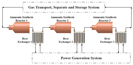
Figure 1.
Braun-type three tower ammonia synthesis exothermic system.
2.1. Physical Model of Ammonia Synthesis Reactors
This paper uses a one-dimensional model, and the ammonia synthesis reactor tower can be simplified to a tubular filled-bed reactor with a large diameter. The gas is thoroughly mixed uniformly in the radial direction, the radial temperature difference inside the reactor and heat exchanger is ignored, and no back-mixing occurs during the axial flow. A model diagram of a tubular filled-bed ammonia synthesis reactor is shown in Figure 2, and its relevant parameters are listed in Table 1.
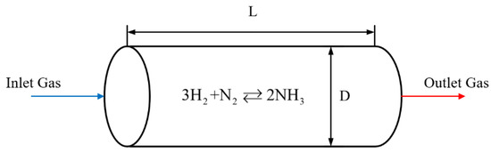
Figure 2.
Tubular filled-bed ammonia synthesis reactor.

Table 1.
Design and operating parameters for reference reactors.
Because the reaction pressure of the ammonia synthesis process reaches 15 MPa and the temperature can achieve 600–800 K, the ideal gas equation of state has a large error. So, all the property parameters involved, such as the specific heat capacity at constant pressure, thermal conductivity, density, and kinetic viscosity are calculated by the REFPROP software developed by NIST.
2.1.1. Reaction Kinetic Equations
The reaction kinetic model for ammonia synthesis obeys the Temkin–Pyzhev reaction rate equation. For real gases, directly calculate the partial pressures of the components by molar fraction is not accurate, so, to keep the equation form simple, activity is introduced into the reaction rate equation [31]:
where, is the ammonia synthesis reaction rate in ; is the partical pressure calculated by the activity coefficient of corresponding substances (, which correspond to hydrogen, nitrogen, ammonia and argon, respectively) in bar; is a constant determined by the state of nitrogen decomposition on the catalyst surface which is taken as 0.75 in this paper [31].
The in Equation (1) is the equilibrium constant of the ammonia synthesis reaction, which is given by the following equations [31]:
where T is the reaction temperature in K; is the molar fraction of the component i; is the parameter in Beattie–Bridgeman equation of state for the pure gas of the component i, which can be found in Table 2 [31].
Table 2.
Parameters in Beattie–Bridgeman Equation [31].
and in Equation (1) essentially characterize the reaction rate constants, which are calculated by [31]:
where R is the universal gas constant, and the global activation energies in Table 3 are used to calculate the chemical reaction rate constants.
Table 3.
Parameters of Equations (4) and (5) [31].
The partial pressure in Equation (1) is equal to the activity coefficient multiplied by the partial pressure of the component [38]:
where and are the activity coefficients and molar fractions of the component i, and p is the total reaction pressure in kPa.
The activity coefficients in Equation (6) are calculated by the following Equation [31]:
where and are given by:
When the temperature is 653 K and the pressure is 15.6 MPa, each component’s partial pressure calculated by molar fraction and actual gas state are listed in Table 4. The overall difference between the results of the two calculations is minimal, but partial pressures calculated by the actual gas equation of state and activity are more accurate.
Table 4.
Comparison of partial pressure.
2.1.2. Conservation Equation
Since the ammonia synthesis reactor is adiabatic, all the reaction heat is absorbed by the gas mixture inside the reactor. So the energy conservation equation in each axial micro-element can be represented by the change in temperature of the reacting gas [39,40]:
where is the cross-sectional area of the reactor in ; is the reaction enthalpy of reaction j in ; is the effective factor of internal diffusion; is the intrinsic reaction rate of reaction in ; is the molar constant pressure heat capacity of component in is the molar flow rate of component in .
The mass conservation equation is expressed by the differential equation for the rate of conversion as follows:
After trial calculations, the Reynolds number of the gas mixture in the reactor ranges from 3000 to 12,000 in the given range of operating parameters, so the momentum conservation in the reactor is characterized by using the Hick’s pressure drop equation as follows [36,41]:
2.1.3. Entropy Generation Rate
The irreversibility losses for irreversible processes can be measured by entropy generation. Entropy generation in the reactor is mainly from the finite rate chemical reaction and the finite pressure-difference fluid flow, so the total entropy generation rate of the microelement length in the reactor is [42,43]:
The total entropy generation rate of the whole reactor is the integral of the total entropy generation rate of the microelement length along the tube length.
2.2. Physical Model of Heat Exchangers
The heat exchanger adopts counter-flow tube bundle heat transfer, with the high-temperature gas mixture from the reactor in the tube process and the water vapor at an initial pressure of 150 kPa and an initial temperature of 150 °C in the shell process. The schematic image of the cooler is shown in Figure 3, and its design parameters is in Table 5.
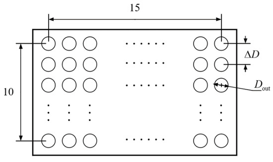
Figure 3.
Cross section of counter flow heat exchanger.
Table 5.
The model parameters of heat exchanger.
The Nusselt number for the heat transfer in the tube flow is calculated using the Gnielinski formula [44]:
The in the Gnielinski formula is the Darcy resistance coefficient for turbulent flow in the tube, calculated from the Filonenko formula [44]:
The same Gnielinski formula is used to express the heat transfer in the shell process flow, but the inner diameter of the pipe in Equation (15) needs to be changed to 4 times the hydraulic radius when calculating the Nu of the shell process.
where is the over-flow area in ; is the wetted circumference in m.
The pressure drop in the heat exchanger comes from the viscous frictional flow process and is calculated using Darcy’s equation [45] for the pressure drop along the flow, i.e.,
The heat transfer coefficients and heat transfer thermal resistance of the tube and shell processes can be obtained by the defined equation of Nu.
The total entropy generation rate in the cooler comes from the finite temperature difference heat transfer and the finite pressure difference flow processes, so the total entropy generation rate of the microelement length is given by [42,43]
3. Optimization Methods
The application of industrial reactors to thermal storage and power generation requires the analysis and optimal design of its structural and operation parameters. In this paper, we analyzed the effects of eight single variables on the total exothermic rate and system entropy generation rate, and the variables includes the inlet molar flow rate, inlet gas hydrogen to nitrogen ratio, three reactor lengths and three reactor inlet temperatures. After that, considering minimum entropy generation rate and maximum exothermic rate, a non-dominated solution ranking genetic algorithm with elite strategy [46,47] (NSGA-II) will be used to optimize a total of seven variables simultaneously, including the inlet molar flow rate, three reactor lengths and three inlet temperatures. Figure 4 is the algorithm flow chart of NSGA-II [48].
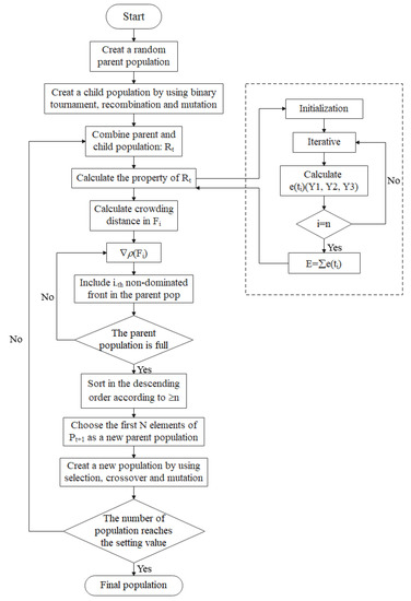
Figure 4.
Algorithm flow chart of NSGA-II.
Automatic machine learning algorithms [49,50,51,52,53,54,55,56,57,58] have been widely used in analysis and optimization in physical and chemical engineering. Liu et al. [51,52,54] used Bayesian optimization [51,52] and deep neural network algorithms [54] in the modelling and analysis of multiphase flow and boiling heat transfer, respectively. They effectively reduced the uncertainty of empirical correlations in complex processes and verified the effectiveness of the algorithms through experiments. For complex uncertain processes, machine learning algorithms have significant advantages on efficiency and accuracy.
All the flow processes of the model in this paper are single-phase, and the correlation formula can effectively express the reaction, flow and heat exchange processes. Confronted with this situation, the NSGA-II algorithm shows obvious advantages in multi-objective optimization. Firstly, the NSGA-II algorithm proposes a fast non-dominated sorting method, which effectively improves the speed of the search. Secondly, the concept of crowding is introduced in the algorithm, which ensures population diversity and effectively avoids falling into local optima. Finally, the inclusion of an elite strategy, which retains the outstanding parent population, can rapidly improve the quality of the population.
3.1. Univariate Analysis
The inlet molar flow rate is a key parameter affecting the total exothermic rate, and usually a larger inlet flow rate will lead to a higher total exothermic rate. Considering the reference reactors inlet flow rate is 132 mol/s, a more suitable molar flow rate for the exothermic scenario is explored in the range of 110–180 mol/s.
The effect of gas hydrogen to nitrogen ratio() on performance is analyzed by controlling the inlet molar flow rate to be constant. Since the stoichiometric ratio of hydrogen to nitrogen in the reaction equation is 3, the hydrogen to nitrogen ratio is continuously varied from 2 to 4 to find a better performing hydrogen to nitrogen ratio.
When the effect of individual reactor length on performance is analyzed, because the length of the reactor 3 is almost twice as long as the reactors 1 and 2, the analysis range for the reactors 1 and 2 is 0.5 m above and below their reference values and the analysis range for the reactor 3 is 1 m above and below the reference value.
When the effect of individual reactor inlet temperature on performance is analyzed, the temperature analysis range for each reactor is 50 K above and below its reference value.
3.2. Multivariate Optimization
The NSGA-II algorithm is one of the most applied multi-objective optimization algorithms, which introduces an elite strategy to ensure that the good individuals of the parent generation are not discarded to improve the optimization accuracy.
Through univariate analysis, the influence of each structural or operation parameter of the reactor on the overall performance is investigated, and combining with the parameters of the reference reactors, the parameter interval of multi-objective optimization is clarified. Finally, with the minimum entropy generation rate and maximum exothermic rate as objectives, a total of seven variables, including inlet molar flow rate, lengths and inlet temperatures of the three reactors, are simultaneously optimized to obtain the Pareto fronts. The objective function and constraints of the optimization problem are as follows:
4. Numerical Example of Univariate Analysis
4.1. Model Validation
The model calculation results obtained at an inlet flow rate of 132 mol/s and the actual engineering results [59,60] are shown in Table 6. The comparison shows that the deviation of the model calculation in this paper is from −3.04% to 17.82%, and the deviation of the final node is only 7.76%. The errors mainly come from that the one-dimensional model ignores the effect of gravity, whereas the actual Braun ammonia synthesis tower is vertical. At the same time, a maximum temperature deviation of 3.04% and a final ammonia molar fraction deviation of 7.76% are acceptable as the paper is concerned with the overall exothermic rate and entropy generation rate. This indicates that this model is accurate and can effectively simulate the exothermic rate of reactor.
Table 6.
Comparison of model results with actual results.
In industry, coke, water vapor and air are used to make reaction gases. Multiple cycles result in an increased content of rare gases in the gas mixture, mainly argon. When this reactor is applied to an ammonia-based thermochemical heat storage system, its inlet reaction gas comes from the front ammonia decomposition heat storage reactor, so it can be assumed that the inlet gas composition contains only hydrogen, nitrogen and ammonia gas. Therefore, the molar fraction of each component of the inlet gas of the reference reactor needs to be adjusted to the data in Table 7.
Table 7.
Components of inlet gas mixture.
4.2. Effect of Inlet Molar Flow Rate on System Performance
The variation of total exothermic rate (ER), total entropy generation rate (SG), ammonia production rate (AP) and exit ammonia molar fraction (AF) with the increase in inlet molar flow rate is shown in Figure 5.
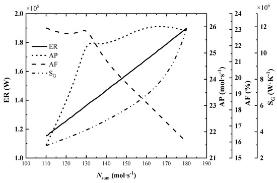
Figure 5.
Effect of inlet molar flow rate on system performance.
As seen in Figure 5, the total exothermic rate increases almost linearly and steadily with the increase in inlet molar flow rate, while the total entropy generation rate climbs sharply. By observing the outlet parameters of each reactor under different flow rates, it is found that the ammonia production rate and exothermic rate increase with the increase in inlet flow rate, but the molar fraction of ammonia and the reactor outlet temperature decrease. This indicates that the reaction is far from the equilibrium state and is more favorable for the advance of positive reaction to improve the exothermic rate continuously. The dramatic increase in the total entropy generation rate is mainly due to the rise of the inlet flow rate and the ammonia synthesis rate, which leads to a significant increase in the entropy generation rate of the flow process and chemical reaction.
In Figure 5, when the inlet molar flow rate is below 130 mol/s, the ammonia production rate increases continuously with the increase in inlet flow rate, and the change of exit ammonia molar fraction is not obvious; after the inlet flow rate exceeds 130 mol/s, the ammonia production rate increases slowly and the exit ammonia molar fraction decreases rapidly.
Therefore, when the inlet molar flow rate is 132 mol/s, the reference value, the reactor has a high AP and AF. This is more in line with the needs of industrial ammonia synthesis. While, for the exothermic reactor, it’s necessary to optimize the inlet molar flow rate.
4.3. Effect of Hydrogen to Nitrogen Ratio on System Performance
The effect of the hydrogen–nitrogen ratio on the system performance is analyzed by increasing the hydrogen-nitrogen ratio() from 2 to 4 at constant inlet flow rates of 120, 130 and up to 180 mol/s, respectively.
Under the constant molar flow rate, the effect of inlet gas hydrogen–nitrogen ratio on the total exothermic rate is not obvious (the maximum change is 1%), and the total exothermic rate shows a slight decrease with the increase in hydrogen-nitrogen ratio. The variation of the total entropy generation rate of the system with the hydrogen to nitrogen ratio is shown in Figure 6.
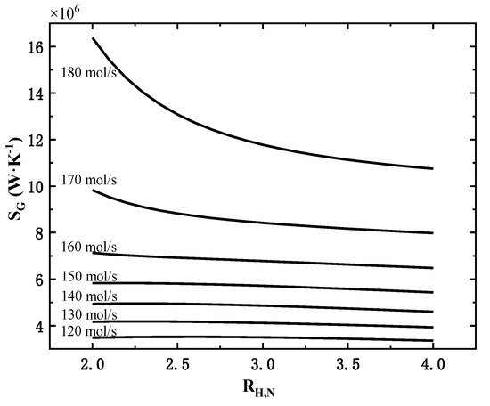
Figure 6.
Effect of hydrogen–nitrogen ratio on the total entropy generation rate at different molar flow rates.
As shown in Figure 6, under different molar flow rates, the variation of total entropy generation rate is different. When the inlet flow rate is 150 mol/s and below, the total entropy generation rate increases slightly and then decreases slowly; when the inlet flow rate is 160 mol/s and above, the total entropy generation rate decreases continuously with the increase in hydrogen-nitrogen ratio, and the larger the inlet flow rate, the more significant this decrease is. So, when the inlet flow rate is large, the hydrogen to nitrogen ratio should be increased as much as possible to effectively reduce the total entropy generation rate with little effect on the total exothermic rate.
The main reason for the above-mentioned rules is that when the inlet flow rate is large and the hydrogen–nitrogen ratio is low (more nitrogen content), the remaining nitrogen content is still high after entering the third tower. The high nitrogen content can effectively promote the ammonia synthesis reaction, making the third reaction tower’s outlet temperature and total entropy generation rate much higher.
4.4. Effect of Each Reactor’s Length on System Performance
In this paper, three reactor towers are involved, so the effect of the variation of the third reactor length on the performance index is analyzed when the other two reactor’s lengths are maintained at reference values. The changes of total exothermic rate and total entropy generation rate corresponding to the variation of each reactor’s length are shown in Figure 7.
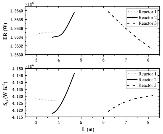
Figure 7.
Effect of single reactor’s length on system performance.
The different lines in Figure 7 represent the length change process of different reactors, and the comparison between the top and bottom shows that: in the calculation range, as the length of reactor 1 increases, the total heat release rate increases and the total entropy generation rate decreases, and the change process tends to be smooth, so reactor 1 should be longer within a reasonable range. The increase in reactor 2 length will incease the total heat release rate and the total entropy generation rate simultaneously. Therefore, it is necessary for reactor 2 to coordinate between the two indexes to obtain a better length. As the length of reactor 3 increases, the total heat release rate decreases and the total entropy generation rate increases, so reactor 3 should be as short as possible.
4.5. Effect of Each Reactor’s Inlet Temperature on System Performance
Similarly, two reactors’ inlet temperatures are controlled as reference values, and the third reactor inlet temperature varies in the range of 50 K above and below the reference value. The effect of individual reactor inlet temperature variations on the total entropy generation rate is shown in Figure 8.
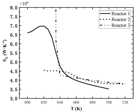
Figure 8.
Effect of single reactor’s inlet temperature on total entropy generation rate.
The effect of inlet temperature on the total exothermic rate is also not obvious, but that on total entropy generation rate is significant. As shown in Figure 8, the total entropy generation rate increases firstly and then decreases rapidly as the inlet temperature of the reactor 1 increases; the total entropy generation rate decreases continuously as the inlet temperature of the reactor 2 increases; for the reactor 3, the total entropy generation rate is extremely high when the inlet temperature is lower than 635 K and decreases sharply as the inlet temperature increases, and it decreases slowly when the inlet temperature is much higher than 635 K.
5. Numerical Example of Multivariate Optimization
Taking minimum entropy generation rate and maximum exothermic rate as objectives, the NSGA-II algorithm [43] is applied to fulfill the multi-objective optimization. The Pareto front obtained is shown in Figure 9.
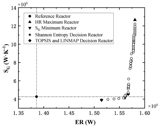
Figure 9.
The Pareto front of multi-objective optimization.
In Figure 8, the solid dot in the lower left corner is the performance index of the reference reactor, and the reference point will divide the Pareto front space in quadrants. The points of Pareto front all locate in the first and fourth quadrants and show a tendency to converge to the lower right corner (ideal point), indicating that the optimal reactors significantly enhance the total exothermic rate. Compared with the reference reactor, the points in the fourth quadrant reduce the entropy generation rate while enhancing the exothermic rate.
Two sets of structural and operation parameters are selected from the Pareto front by three fuzzy decision methods, i.e., TOPSIS [61,62,63], LINMAP [64,65] and Shannon Entropy [66,67,68]. The optimal reactors determined by different decision methods are labeled in Figure 9, and the related parameters are listed in Table 8. Finally, based on the deviation index (DI) of the two decision points, the Shannon Entropy decision reactor is chosen as the optimized reactor. The DI is the ratio of the distance of the decision point from the optimized solution to the sum of the distance of the decision point from the optimized solution and the worst solution. The smaller the DI, the better the results.
Table 8.
Decision reactors’ parameters in multi-objective optimization.
The Dideal is the distance from the decision point to the ideal point and the Dnon is the distance from the decision point to the non-ideal point.
6. Conclusions
In this paper, a one-dimensional model of Braun-type ammonia synthesis exothermic reactor is established based on finite-time thermodynamics, and the effects of parameters such as inlet molar flow rate, hydrogen-nitrogen ratio, reactor length, and reactor inlet temperature on system performance are analyzed. The Pareto front is obtained by NSGA-II algorithm, and three decision methods including TOPSIS, LINMAP and Shannon Entropy, are applied to obtain optimal reactors. The analysis and optimization results show that:
- The inlet molar flow rate is the key parameter affecting the total exothermic rate of the system. The total exothermic rate basically increases linearly with the increase in the molar flow rate, but the total entropy generation rate climbs sharply.
- Under the constant inlet molar flow rate, the change of hydrogen to nitrogen ratio has little effect on the total exothermic rate. But when the molar flow rate is large, the hydrogen to nitrogen ratio has an obvious effect on the total entropy generation rate, and a higher hydrogen to nitrogen ratio should be chosen for large molar flow rate.
- Compared with the reference reactor, the TOPSIS and LINMAP optimal reactor improves the total exothermic rate by 13.1% and the total entropy generation rate by 6.7%; the Shannon entropy optimal reactor improves the total exothermic rate by 12.6% and reduces the total entropy generation rate by 3.4%.
- According to the deviation index, the Shannon Entropy optimal reactor is choosen as the optimized reactor.
Author Contributions
Conceptualization, S.X.; Funding Acquisition, S.X.; Methodology, T.X., C.W. and S.X.; Software, T.X. and S.X.; Validation, S.X.; Writing—Original Draft, T.X. and C.W.; Writing—Review and Editing, S.X. All authors have read and agreed to the published version of the manuscript.
Funding
This work is supported by the National Natural Science Foundation of China (Grant Nos. 51976235 and 51606218) and Independent Project of Naval University of Engineering (No. 20161504).
Data Availability Statement
Not applicable.
Conflicts of Interest
The authors declare no conflict of interest.
Nomenclature
| Cross-section area, | |
| Molar heat capacity, | |
| D | Diameter, m |
| Molar flow rate, | |
| Kp | Equilibrium constant |
| Length, | |
| Molar mass, | |
| Prandtl number | |
| Reaction pressure, Pa | |
| Universal gas constant, | |
| Molar fraction of component i | |
| Reynolds number | |
| Chemical reaction rate, | |
| SG | Entropy generation rate, |
| Temperature, K | |
| Activity coefficient of partial pressure | |
| Porosity | |
| Dynamic viscosity, | |
| Local entropy generate rate, | |
| Density, | |
| Covariate variable vector | |
| activity coefficient | |
| Gibbs free energy change of reaction, | |
| Enthalpy of reaction, | |
| AP | Ammonia production rate |
| AF | Exit ammonia molar fraction |
| ER | Total exothermic rate |
References
- Luzzi, A. High temperature solar tests with 1kWchem ammonia reactor. Fuel Energy Abstr. 1995, 36, 271. [Google Scholar]
- Luzzi, A.; Lovegrove, K.; Filippi, E.; Fricker, H.; Schmitz-Goeb, M.; Chandapillai, M.; Kaneff, S. Techno-economic analysis of a 10 MW solar thermal power plant using ammonia-based thermochemical energy storage. Sol. Energy 1999, 66, 91–101. [Google Scholar] [CrossRef]
- Lovegrove, K.; Luzzi, A. Endothermic reactors for an ammonia based thermochemical solar energy storage and transport system. Sol. Energy 1996, 56, 361–371. [Google Scholar] [CrossRef]
- Lovegrove, K.; Luzzi, A.; Soldiani, I.; Kreetz, H. Developing ammonia based thermochemical energy storage for dish power plants. Sol. Energy 2004, 76, 331–337. [Google Scholar] [CrossRef]
- Kreetz, H.; Lovegrove, K.; Luzzi, A. Maximizing thermal power output of an ammonia synthesis reactor for a solar thermochemical energy storage system. J. Energy Eng. 2001, 123, 75–82. [Google Scholar] [CrossRef]
- Kreetz, H.; Lovegrove, K. Exergy analysis of an ammonia synthesis reactor in a solar thermochemical power system. Sol. Energy 2002, 73, 187–194. [Google Scholar] [CrossRef]
- Long, X.F.; Liao, K. Numerical simulation of ammonia-based exothermic reactor used in solar thermal power generation. J. South China Univ. Technol. 2008, 36, 21–25. (In Chinese) [Google Scholar]
- Chen, C.; Lovegrove, K.; Sepulveda, A.; Lavine, A.S. Design and optimization of an ammonia synthesis system for ammonia-based solar thermochemical energy storage. Sol. Energy 2018, 159, 992–1002. [Google Scholar] [CrossRef]
- Chen, C.; Aryafar, H.; Lovegrove, K.; Lavine, A.S. Modeling of ammonia synthesis to produce supercritical steam for solar thermochemical energy storage. Sol. Energy 2017, 155, 363–371. [Google Scholar] [CrossRef]
- Abdiwe, R.A.; Haider, M. A mathematical model for ammonia solar and synthesis reactors. Renew. Wind. Water Sol. 2016, 3, 1–7. [Google Scholar] [CrossRef]
- Flórez-Orrego, D.; de Oliveira Junior, S. Modeling and optimization of an industrial ammonia synthesis unit: An exergy approach. Energy 2017, 137, 234–250. [Google Scholar] [CrossRef]
- Flórez-Orrego, D.; de Oliveira Junior, S. On the efficiency, exergy costs and CO2 emission cost allocation for an integrated syngas and ammonia production plant. Energy 2016, 117, 341–360. [Google Scholar] [CrossRef]
- Ksasy, M.; Areed, F.; Saraya, S.; Khalik, M.A. Optimal reactor length of an auto-thermal ammonia synthesis reactor. Int. J. Elec. Comput. Sci. 2010, 10, 6–11. [Google Scholar]
- Babu, B.V.; Angira, R. Optimal design of an auto-thermal ammonia synthesis reactor. Comput. Chem. Eng. 2005, 29, 1041–1045. [Google Scholar] [CrossRef]
- Chen, L.G.; Xia, S.J. Processes in generalized thermodynamic dynamic-optimization of irreversible processes. Sci. Sin. Tech. 2019, 49, 981–1022. (In Chinese) [Google Scholar] [CrossRef]
- Chen, L.G.; Xia, S.J.; Feng, H.J. Processes in generalized thermodynamic dynamic-optimization of irreversible cycles. Sci. Sin. Tech. 2019, 49, 1223–1267. (In Chinese) [Google Scholar] [CrossRef]
- Bejan, A. The concept of irreversibility in heat exchanger design: Counterflow heat exchangers for gas-to-gas applications. J. Heat Trans. 1977, 99, 374–380. [Google Scholar] [CrossRef]
- Bejan, A. Notes on the history of the method of entropy generation minimization (finite time thermodynamics). J. Non-Equilib. Thermody. 1996, 21, 239–242. [Google Scholar]
- Chen, L.G.; Feng, H.J.; Ge, Y.L. Power and efficiency optimization for open combined regenerative Brayton and inverse Brayton cycles with regeneration before the inverse cycle. Entropy 2020, 22, 677. [Google Scholar] [CrossRef]
- Chen, L.G.; Ge, Y.L.; Liu, C.; Feng, H.J.; Lorenzini, G. Performance of universal reciprocating heat-engine cycle with variable specific heats ratio of working fluid. Entropy 2020, 22, 397. [Google Scholar] [CrossRef]
- Goupil, C.; Herbert, E. Adapted or adaptable: How to manage entropy production? Entropy 2019, 22, 29. [Google Scholar] [CrossRef] [PubMed]
- Tsirlin, A.; Gagarina, L. Finite-time thermodynamics in economics. Entropy 2020, 22, 891. [Google Scholar] [CrossRef] [PubMed]
- Yasunaga, T.; Ikegami, Y. Finite-time thermodynamic model for evaluating heat engines in ocean thermal energy conversion. Entropy 2020, 22, 211. [Google Scholar] [CrossRef] [PubMed]
- Rogolino, P.; Cimmelli, V.A. Thermoelectric efficiency of Silicon–Germanium alloys in finite-time thermodynamics. Entropy 2020, 22, 1116. [Google Scholar] [CrossRef]
- Koeijer, G.D.; Rosjorde, A.; Kjelstrup, S. Distribution of heat exchange in optimum diabatic distillation columns. Energy 2004, 29, 2425–2440. [Google Scholar] [CrossRef]
- Kjelstrup, S.; Koeijer, G.M. Transport equations for distillation of ethanol and water from the entropy production rate. Chem. Eng. Sci. 2003, 58, 1147–1161. [Google Scholar] [CrossRef]
- Andresen, B.; Essex, C. Eigentimes and very slow processes. Entropy 2017, 19, 492. [Google Scholar] [CrossRef]
- Andresen, B.; Essex, C. Thermodynamics at very long time and space scales. Entropy 2020, 22, 1090. [Google Scholar] [CrossRef] [PubMed]
- Andresen, B. Metrics and energy landscapes in irreversible thermodynamics. Entropy 2015, 17, 6304–6317. [Google Scholar] [CrossRef]
- Nummedal, L.; Kjelstrup, S.; Costea, M. Minimizing the entropy production rate of an exothermic reactor with a constant heat-transfer coefficient: The ammonia reaction. Ind. Eng. Chem. Res. 2003, 42, 1044–1056. [Google Scholar] [CrossRef]
- Maansson, B.; Andresen, B. Optimal temperature profile for an ammonia reactor. Ind. Eng. Chem. Process Des. Dev. 1986, 25, 59–65. [Google Scholar] [CrossRef]
- Badescu, V. Optimal design and operation of ammonia decomposition reactors. Int. J. Energy Res. 2020, 44, 5360–5384. [Google Scholar] [CrossRef]
- de Koeijer, G.; Johannessen, E.; Kjelstrup, S. The second law optimal path of a four-bed SO2 converter with five heat exchangers. Energy 2004, 29, 525–546. [Google Scholar] [CrossRef]
- Kong, R.; Chen, L.; Xia, S.; Li, P.; Ge, Y. Minimization of entropy generation rate in hydrogen iodide decomposition reactor heated by high-temperature helium. Entropy 2021, 23, 82. [Google Scholar] [CrossRef]
- Kong, R.; Chen, L.; Xia, S.; Li, P.; Ge, Y. Performance analysis of hydrogen iodide decomposition membrane reactor under different sweep modes. Energy Convers. Manag. 2021, 244, 114436. [Google Scholar] [CrossRef]
- Li, P.; Chen, L.; Xia, S.; Zhang, L.; Kong, R.; Ge, Y.; Feng, H. Entropy generation rate minimization for steam methane reforming reactor heated by molten salt. Energy Reps. 2020, 6, 685–697. [Google Scholar] [CrossRef]
- Li, P.; Chen, L.; Xia, S.; Zhang, L. Entropy generation rate minimization for methanol synthesis via a CO2 hydrogenation reactor. Entropy 2019, 21, 174. [Google Scholar] [CrossRef]
- Elias, I.F. Thermodynamics with Chemical Engineering Applications; Cambridge University Press: London, UK, 2014. [Google Scholar]
- Xie, T.C.; Xia, S.J.; Wang, C. Multi-objective performance optimization of ammonia decomposition thermal storage reactor. E3S Web Conf. 2021, 267, 2073. [Google Scholar] [CrossRef]
- Li, P.L.; Chen, L.G.; Xia, S.J.; Zhang, L. Maximum hydrogen production rate optimization for tubular steam methane reforming reactor. Int. J. Chem. React. Eng. 2019, 17, 9. [Google Scholar] [CrossRef]
- Hicks, R.E. Pressure drop in packed beds of spheres. Ind. Eng. Chem. Fundam. 1970, 9, 500–502. [Google Scholar] [CrossRef]
- Groot, S.R.; Mazur, P. Non-Equilibrium Thermodynamics; Dover: London, UK, 1984. [Google Scholar]
- Kjelstrup, S.; Bedeaux, D.; Johannessen, E.; Gross, G. Non-Equilibrium Thermodynamics for Engineers; World Scientific: Singapore, 2010. [Google Scholar]
- Kubie, J.; Tariq, M.; Grassie, T. Heat Transfer: A Problem-Solving Approach; Routledge: London, UK, 2012. [Google Scholar]
- Robert, A.G. Fluid Mechanics; Dover Publications: New York, NY, USA, 2012. [Google Scholar]
- Deb, K.; Pratap, A.; Agarwal, S.; Meyarivan, T. A fast and elitist multiobjective genetic algorithm: NSGA-II. IEEE T Evolut. Comput. 2002, 6, 182–197. [Google Scholar] [CrossRef]
- Tian, Y.; Cheng, R.; Zhang, X.; Jin, Y. PlatEMO: A MATLAB platform for evolutionary multi-objective optimization [Educational Forum]. IEEE Comput. Intell. Mag. 2017, 12, 73–87. [Google Scholar] [CrossRef]
- Zhang, R.Z. A study of industrial structure optimization under economy, employment and environment constraints based on MOEA. In International Conference on Bio-Inspired Computing: Theories and Applications; Springer: Singapore, 2018; pp. 120–132. [Google Scholar]
- Angelikopoulos, P.; Papadimitriou, C.; Koumoutsakos, P. Bayesian uncertainty quantification and propagation in molecular dynamics simulations: A high performance computing framework. J. Chem. Phys. 2012, 137, 9–512. [Google Scholar] [CrossRef]
- Meredig, B.; Agrawal, A.; Kirklin, S.; Saal, J.; Doak, J.; Thompson, A.; Zhang, K.; Choudhary, A.; Wolverton, C. Combinatorial screening for new materials in unconstrained composition space with machine learning. Phys. Rev. B 2014, 89, 094104. [Google Scholar] [CrossRef]
- Liu, Y.; Sun, X.; Dinh, N. Validation and uncertainty quantification of multiphase-CFD solvers: A data-driven Bayesian framework supported by high-resolution experiments. Nucl. Eng. Des. 2019, 354, 110200. [Google Scholar] [CrossRef]
- Liu, Y.; Wang, D.; Sun, X.; Dinh, N.; Hu, R. Uncertainty quantification for Multiphase-CFD simulations of bubbly flows: A machine learning-based Bayesian approach supported by high-resolution experiments. Reliab. Eng. Syst. Saf. 2021, 212, 107636. [Google Scholar] [CrossRef]
- Liu, Y.; Dinh, N. Validation and uncertainty quantification for wall boiling closure relations in multiphase-CFD solver. Nucl. Sci. Eng. 2019, 93, 81–99. [Google Scholar] [CrossRef]
- Liu, Y.; Dinh, N.; Sato, Y.; Niceno, B. Data-driven modeling for boiling heat transfer: Using deep neural networks and high-fidelity simulation results. Appl. Therm. Eng. 2018, 144, 305–320. [Google Scholar] [CrossRef]
- Mostafavi, E.S.; Mostafavi, S.I.; Jaafari, A.; Hosseinpour, F. A novel machine learning approach for estimation of electricity demand: An empirical evidence from Thailand. Energy Convers. Manag. 2013, 74, 548–555. [Google Scholar] [CrossRef]
- Schütt, K.T.; Glawe, H.; Brockherde, F.; Sanna, A.; Müller, K.R.; Gross, E. How to represent crystal structures for machine learning: Towards fast prediction of electronic properties. Phys. Rev. B 2013, 89, 163–168. [Google Scholar] [CrossRef]
- Trees, H.V.; Bell, K.L.; Dosso, S. Bayesian bounds for parameter estimation and nonlinear filtering/tracking. J. Acoust. Soc. Am. 2008, 123, 2460. [Google Scholar]
- De Vita, A.; Li, Z.; Kermode, J.R. Molecular Dynamics with On-the-Fly Machine Learning of Quantum-Mechanical Forces. Phys. Rev. Lett. 2015, 114, 96405. [Google Scholar]
- Zheng, Z.L. Introduction to the structure of a Braun Process ammonia synthesis tower. Chem. Equip. Des. 1991, 4, 29–32. [Google Scholar]
- Chen, Q.Q. A Simulation of the Ammonia Synthesis Reactor and Process; East China University of Science and Technology: Shanghai, China, 2011. [Google Scholar]
- Chen, C.T. Extensions of the TOPSIS for group decision-making under fuzzy environment. Fuzzy Sets Syst. 2000, 114, 1–9. [Google Scholar] [CrossRef]
- Opricovic, S.; Tzeng, G.H. Compromise solution by MCDM methods: A comparative analysis of VIKOR and TOPSIS. Eur. J. Oper. Res. 2004, 156, 445–455. [Google Scholar] [CrossRef]
- Shih, H.S.; Shyur, H.J.; Lee, E.S. An extension of TOPSIS for group decision making. Math. Comput. Model. 2007, 45, 801–813. [Google Scholar] [CrossRef]
- Xia, H.; Li, D.; Zhou, J.; Wang, J. Fuzzy LINMAP method for multiattribute decision making under fuzzy environments. J. Comput. Ssyt. Sci. 2006, 72, 741–759. [Google Scholar] [CrossRef]
- Chen, T.Y. An interval-valued intuitionistic fuzzy LINMAP method with inclusion comparison possibilities and hybrid averaging operations for multiple criteria group decision making. Knowl-Based Syst. 2013, 45, 134–146. [Google Scholar] [CrossRef]
- Guisado, J.L.; Jiménez-Morales, F.; Guerra, J.M. Application of shannon’s entropy to classify emergent behaviors in a simulation of laser dynamics. Math. Comput. Model. 2005, 42, 847–854. [Google Scholar] [CrossRef]
- Lotfi, F.H.; Reza, F. Imprecise Shannon’s Entropy and Multi Attribute Decision Making. Entropy 2010, 12, 53–62. [Google Scholar] [CrossRef]
- Yang, W.; Xu, K.; Lian, J.; Ma, C.; Bin, L. Integrated flood vulnerability assessment approach based on TOPSIS and Shannon entropy methods. Ecol. Indic. 2018, 89, 269–280. [Google Scholar] [CrossRef]
Publisher’s Note: MDPI stays neutral with regard to jurisdictional claims in published maps and institutional affiliations. |
© 2021 by the authors. Licensee MDPI, Basel, Switzerland. This article is an open access article distributed under the terms and conditions of the Creative Commons Attribution (CC BY) license (https://creativecommons.org/licenses/by/4.0/).