Abstract
The analysis and design of reinforced concrete members (such as beams, columns, and shear walls) is fundamental to civil and structural engineering. Classical design methods based on hand calculations or interaction diagrams are available for various reinforced concrete sections. The goal of this study is to develop a new alternative design method for reinforced concrete shear walls using mathematical programming and numerical optimization. The design of reinforced concrete shear walls is based on the latest American Concrete Institute ACI 318-19 Code. The design method relies on an optimization formulation to determine the minimum required steel area subject to given factored loads (such as a combined bending moment and axial force on a concrete section). This study intends to present the design of concrete shear wall sections in a rigorously derived framework using different formulations. To make it more practical for civil and structural engineers to use, a widely available numerical solver in a Microsoft Excel spreadsheet is adopted as the optimization engine. Concrete shear wall examples are analyzed and designed using the proposed method, and the results are compared with those obtained using classical design methods. The new method using numerical optimization works well and is easy to implement in an Excel spreadsheet. The proposed design method provides a useful alternative for practical engineering applications.
1. Introduction
Design optimization of reinforced concrete structures has been investigated for many years [1,2]. The purpose of this research was to employ optimization methods in order to create practical and easily employed methods to solve reinforced concrete analysis and design problems. Ordinary reinforced concrete design is a tedious and iterative process in which multiple methods can be employed to approach a problem. Certain solutions can take many design iterations to reach and are often overly conservative. Using optimization methods and the Microsoft Excel solver for practicality and ease of use, the ordinary shear wall was designed with the goal of minimizing the total steel area in the shear wall for given loading criteria. This was employed as concrete shear walls are often conservatively designed as columns using interaction diagrams and the amount of steel used may be overconservative. The method involved the use of a thin continuous plate of steel over the length of the shear wall in place of individual bars. The plate was then discretized into smaller elements with each element representing a small area of the total steel area. Using the Excel solver, the program determined the smallest allowable total steel area based on the given loading criteria and shear wall dimensions.
2. Ordinary Shear Wall Design Using Optimization and Element Method
2.1. Optimization Formulation
The design objective was to minimize the total steel area in a shear wall, as:
C(As) = As
To analyze the required vertical steel area, the steel was modeled as a continuous plate and broken up into individual elements, with each element representing a portion of the total steel area. Multiple iterations were run in which the number of elements was varied to achieve convergence and verify the results for the required steel area. The Excel solver was used and equations for moment equilibrium, axial load equilibrium, and concrete analysis (Appendix A) were programed to determine the optimized area of steel per element and hence the optimized total area of steel. The equilibrium equations were treated as equality constraints in numerical optimization.
2.2. Element Analysis and Design Theory
The element method consisted of splitting the steel plate into individual elements, with each element having its own length based on the number of elements “n” (Equations (2) and (3)). The depth “d” used for the moment capacity of the shear wall was taken at the middle of each element with the assumption that all the steel area was centered in the middle of the element (Equations (4) and (5)). The total steel area was split equally amongst all the elements based on the number of elements “n” used. Figure 1 shows the concept of how the steel plate was divided into elements and how the area and depth were found.
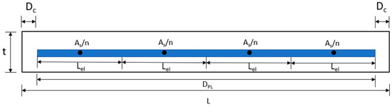
Figure 1.
Concept of the element design method.
Using this method allowed for the elements to act as individual bars with their own required steel area based on the given loading criteria and for the depth and number of elements to be varied based on user input. In order to determine the total steel area required, the total steel area was input as a variable that the solver determined based on the loading and dimension of the wall.
Length of continuous steel plate:
In Equation (2), the length of the continuous plate is found using the length of the wall “L” and subtracting the on-center concrete cover on each side.
dpl = L − 2 × (Concrete Cover)
Length of each steel element:
In Equation (3), the length of each element is found by taking the length of the plate “dpl” and dividing it by the number of elements “n”, which are determined by user input.
Lel = dpl/n
Individual steel area of each element:
In Equation (4), the area of the steel per element is found by taking the total steel area “As” and dividing by the number of elements “n”.
Asel = As/n
Depth of each steel element:
The depth of elements “del” used for the analysis of the moment capacity for each steel element was found by taking the concrete cover and the length of each element “Lel” and multiplying by the number of the individual element minus half to obtain the depth to the middle of each individual element.
del = Concrete Cover + (ni − 0.5) × Lel
2.3. Numerical Example Results
Using a design example from Reference [1] (See Figure 2), a 20′-0″ long by 10″ thick ordinary concrete shear wall was designed, and the results were compared to the results obtained using interaction diagrams in the textbook. The wall was to support a combined design axial compression of 1036 kips and a design moment of 15,162 kips. For this example, the number of elements was varied and two cases were used, the first using 24 elements and the second using 100 elements to determine if the spreadsheet was able to achieve convergence. The final steel area was added amongst the elements to obtain the total steel area required and this was compared to the results found in the textbook, which were designed using interaction diagrams. The results comparing the total steel areas from the textbook and the spreadsheet can be found in Table 1. The results showed a small percentage difference between the total steel areas found using the proposed method and the results using the interaction diagram in the textbook.
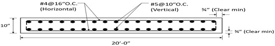
Figure 2.
Reinforced concrete shear wall design example [1].

Table 1.
Element analysis design results vs. interaction diagram design results.
The results showed convergence amongst a variable number of elements as well as showing results within 1% error of those using interaction diagrams. The optimization-based method and Excel spreadsheet allow for ease of use as well as various user inputs based on the desire of the user while providing accurate results to that of shear walls designed using interaction diagrams. More examples will allow for the further contribution and design of the sheet and will be needed to look at the complexity of design that the sheet and Excel solver can handle.
3. Summary and Future Work
In this research, an alternative analysis and design method was developed and applied to reinforced concrete shear walls. A numerical example was studied and the proposed method worked well, and the results were compared with those obtained using the classical methods. The new method using numerical optimization was easy to implement in an Excel spreadsheet, which is useful for practical engineering applications. Future research includes extending the new approach to the design of other concrete structures and members.
Supplementary Materials
The presentation materials can be downloaded at: https://www.mdpi.com/article/10.3390/IOCBD2023-15198/s1.
Author Contributions
Conceptualization, Q.W. and D.H.; methodology, Q.W.; validation, M.C.; writing—original draft preparation, M.C.; writing—review and editing, Q.W. and D.H. All authors have read and agreed to the published version of the manuscript.
Funding
This research received no external funding.
Institutional Review Board Statement
Not applicable.
Informed Consent Statement
Not applicable.
Data Availability Statement
Data from this research is available upon request.
Conflicts of Interest
The authors declare no conflict of interest.
Appendix A
Below are the equations used in the design and analysis of the spreadsheet that are inherent equations used in the analysis and design of concrete members, which are not exclusive to the design and use of this sheet [2].
εti = [(di − c)/c] εcu
Equation (A1) shows how the strain for an individual element’s steel area is obtained.
fi = fy IF εti > εy
fi = −fy IF εti > −εy
fi = E × εti IF −εy < εti < εy
Equations (A2)–(A4) show how the stress in each element’s steel area was obtained based on the corresponding strain of each element.
Fi = Asi(fi − 0.85(fc’)) IF fi < 0
Fi = Asify IF fi > 0
Equations (A5) and (A6) show how the force in each element was obtained based on the corresponding steel stress in each element.
dmi = di − L/2
Equation (A7) shows how the moment arm for each steel element was obtained.
Mn = Fidi
Equation (A8) shows how the moment capacity was found for each steel element.
εt = [(dt − c)/c] εcu
Equation (A9) shows how the actual strain of the extreme layer of steel was calculated.
Φ = 0.65 + (εt − εy)(0.25/0.003)
Equation (A10) shows how the strength reduction factor was calculated.
a = β1c
Equation (A11) shows how the depth of the concrete compressive stress block was calculated.
Ac = abw
Equation (A12) shows how the total area of the concrete in compression was calculated.
Cc = 0.85(Acfc′)
Equation (A13) shows how the resultant concrete compression force was calculated.
Equation (A14) shows how the centroid of the concrete compressive stress block was calculated.
Equation (A15) shows how the depth of the concrete area in compression was calculated.
Eaxial = Cc − Σ(Fi)I − Pu/Φ
Equation (A16) shows how the error of axial load equilibrium was determined.
Equation (A17) shows how the moment capacity was determined.
Equation (A18) shows how the error of moment equilibrium was determined.
References
- Pincheira, J.A.; Parra-Montesinos, G.J.; Wang, C.K.; Salmon, C.G. Reinforced Concrete Design, 9th ed.; Oxford University Press: New York, NY, USA, 2017. [Google Scholar]
- Wang, Q.; Quayyum, S. Flexural Design of Reinforced Concrete Beam Sections according to ACI-318-19: Part 1. STRUCTURE Magazine, 16 April 2023; 36–39. [Google Scholar]
Disclaimer/Publisher’s Note: The statements, opinions and data contained in all publications are solely those of the individual author(s) and contributor(s) and not of MDPI and/or the editor(s). MDPI and/or the editor(s) disclaim responsibility for any injury to people or property resulting from any ideas, methods, instructions or products referred to in the content. |
© 2023 by the authors. Licensee MDPI, Basel, Switzerland. This article is an open access article distributed under the terms and conditions of the Creative Commons Attribution (CC BY) license (https://creativecommons.org/licenses/by/4.0/).