Article

Efficient Runtime Firmware Update Mechanism for LoRaWAN Class A Devices

by
Bernardino Pinto Neves
1,2,*,
António Valente
1,3 and
Victor D. N. Santos
4,5
1
Engineering Department, School of Sciences and Technology, University of Trás-os-Montes and Alto Douro (UTAD), Quinta de Prados, 5000-801 Vila Real, Portugal
2
ENEIDA, Grid Intelligence, S.A., Rua Alexandre Herculano 21B, 3000-019 Coimbra, Portugal
3
INESC Technology and Science, 4200-465 Porto, Portugal
4
Polytechnic Institute of Coimbra, Coimbra Institute of Engineering, Rua Pedro Nunes-Quinta da Nora, 3030-199 Coimbra, Portugal
5
INESC Coimbra, DEEC, Polo II, 3030-290 Coimbra, Portugal
*
Author to whom correspondence should be addressed.
Eng 2024, 5(4), 2610-2632; https://doi.org/10.3390/eng5040137
Submission received: 27 August 2024 / Revised: 30 September 2024 / Accepted: 11 October 2024 / Published: 14 October 2024
(This article belongs to the Section Electrical and Electronic Engineering)

Abstract

:
This paper presents an efficient and secure method for updating firmware in IoT devices using LoRaWAN network resources and communication protocols. The proposed method involves dividing the firmware into fragments, storing them in the application server’s database, and transmitting them to remote IoT devices via downlink messages, without necessitating any changes to the device’s class. This approach can be replicated across any IoT LoRaWAN device, offering a robust and scalable solution for large-scale firmware updates while ensuring data security and integrity. The proposed method significantly reduces the downtime of IoT devices and enhances the energy efficiency of the update process. The method was validated by updating a block in the program memory, associated to a specific functionality of the IoT end device. The associated Intel Hex file was segmented into 17 LoRaWAN downlink frames with an average size of 46 bytes. Upon receiving the complete firmware update, the microcontroller employs self-programming techniques that restrict the update process to specific rows of the program memory, avoiding interruptions or reboots. The update process was successfully completed in 51.33 ms, resulting in a downtime of 16.88 ms. This method demonstrates improved energy efficiency compared to existing solutions while preserving the communication network’s capacity, making it an adequate solution for remote devices in LoRaWAN networks.

Graphical Abstract

1. Introduction

Firmware updates in Internet of Things (IoT) devices arise from the need to add new functionalities and correct vulnerabilities and errors identified during the devices’ lifecycle [1]. The dispersed location and high numbers of devices typically associated with an IoT application preclude an individualized implementation of firmware updates. For instance, in a smart agricultural plantation, dozens or hundreds of humidity and temperature sensors are spread across a vast area, making manual update of each device impractical. To optimize this process, the resources of a wireless communication network are utilized, specifically the LoRaWAN network. The limitations of LoRaWAN networks impose additional challenges for performing firmware updates efficiently and securely due to the reduced offered data rates and available duty cycle values. The aforementioned application requires regular updates usually associated with minor changes (bug fixes or updates to specific features), but low data rates and duty cycle restrictions of the LoRaWAN network can lead to delays and failures in transmitting update data.
Recent studies have explored methods to optimize the firmware update process in IoT devices. Jongboom, J. [1] highlights the challenges of updating firmware in remote devices using low-power networks compared to cellular and wireless networks. This work emphasizes the critical role of firmware updates in maintaining the security and functionality of IoT devices and the difficulties associated with transmitting large data volumes over low-power networks.
Another pertinent study by Schäfer, B. [2] proposes the usage of multicast messages to facilitate efficient and secure firmware updates over LoRaWAN networks. The author advocates the division of the update process into multiple stages, such as signature verification and update status monitoring, to minimize energy consumption and transmission time. However, this method encounters significant challenges due to the high packet loss rate inherent in LoRaWAN networks.
The analysis of related work reveals that most studies involve transmitting the entire program memory image in small fragments. Consequently, a substantial volume of available memory in IoT devices is required to successfully execute the firmware update process, as it necessitates locally reconstructing the firmware image and maintaining a backup code copy. The downtime during the update process is also considerable, typically lasting several minutes. Additionally, significant attention is given to the security of firmware updates, with two primary research areas identified: management mechanisms and security mechanisms for firmware updates over LoRaWAN networks.
This article presents an innovative method for firmware updates in IoT devices using LoRaWAN networks, focusing on transmitting only the program instructions that need modification or addition. This approach addresses several limitations and challenges identified in previous research, particularly remote firmware updates with minimal service interruption. The proposed approach represents a paradigm shift in firmware updates for IoT devices. Unlike multicast transmission models, our method enables peer-to-peer firmware updates at the application layer of IoT devices, significantly reducing radio transmission usage. This approach offers several advantages: it eliminates the need to reconstruct firmware images on the devices, removes the necessity for bootloaders, and ensures efficient use of available flash memory and communication resources. Additionally, it significantly reduces downtime, making the system simpler and more accessible.
To demonstrate the effectiveness of the proposed update mechanism, we developed an IoT application based on a proprietary end device equipped with sensors, actuators, a LoRaWAN transceiver, and an 8-bit microcontroller. The LoRaWAN gateways and The Things Network servers are utilized to provide communication capabilities and interface the end devices with the application server.
To fix a bug in the developed firmware and validate the proposed method, instead of sending the full-image update that comprises 108 kBytes, only 643 bytes were transferred via LoRaWAN. This corresponds to a data reduction of 99.42 per cent compared to the traditional approach. The proposed method significantly reduces the data required for firmware updates, preserving network capacity and reducing transmission time.
Furthermore, the developed procedure maintains the IoT device’s class throughout the update process, ensuring data integrity and security without switching to other classes. This is crucial for maintaining energy efficiency and operational simplicity. Moreover, experimental results show a substantial decrease in device downtime, reduced to just 16.88 ms, compared to several minutes required by other methods. This minimal downtime is particularly beneficial for applications requiring high availability and continuous operation.
Additionally, the proposed method optimizes energy consumption, crucial for Class A IoT devices, by minimizing active transmission time and reducing the computational load associated with firmware updates. Unlike conventional methods that require a complete reboot or use bootloaders, our approach enables updates during runtime without rebooting, enhancing system efficiency and robustness. This study presents an innovative contribution to the field of firmware updates in IoT devices, offering a scalable and robust solution that can be broadly applied across different IoT applications.
This document is organized as follows: Section 2 presents related work, Section 3 contains the proposed methodology, Section 4 discusses the obtained results and compares them with related work, and Section 5 presents conclusions and suggestions for future work.

2. Related Work

Several notable studies are analyzed concerning the optimization of firmware update, with particular focus on update management mechanisms in LoRaWAN networks (update file transmission) and firmware update processes at the IoT device microcontroller level.
In the domain of optimizing firmware image transmission mechanisms in LoRaWAN networks, Dirk Pesch et al. [3] address the concept of Firmware Update Over The Air (FUOTA) and present the limitations of LoRaWAN networks to perform mass data transfer associated with the full firmware image. The study also references the specifications defined by the LoRa Alliance (Fremont, CA, USA), essential for FUOTA implementation in LoRaWAN, through the implementation of a FUOTA simulator to quantify and/or evaluate various FUOTA parameters in terms of firmware update efficiency and device energy consumption. From the analysis, the authors note that the lifespan of an IoT device is too long, making it important to develop mechanisms that allow downlink data transmission without the need for uplink transmissions to be sent first, thus making the update process more efficient. The study also introduces innovative concepts such as the collaborative FUOTA concept using multiple gateways, where the underlying idea involves continuous stream of data distributed across several gateways.
Mavromatis, I. et al. [4] discuss the importance of regular firmware updates in Low-Power Wide Area Networks (LPWANs) to ensure system security and stability. The authors recognize that implementing firmware updates in large-scale networks presents a crucial challenge for environments with a large number of IoT devices. The article analyzes the behavior of advanced protocols under adverse conditions, classifying network performance and quality. The study provides a detailed view of how an LPWAN system behaves during a large-scale firmware update, depending on the type of protocol implemented. From the analysis, the study concludes that adopting protocols such as Atomic and Synchronous Flooding can significantly improve the effectiveness of firmware updates in large-scale LPWAN networks and that precise configuration adjustments are essential to optimize performance in different deployment contexts compared to traditional protocols like CSMA-CA.
Charilao et al. [5] propose a methodology for evaluating the firmware update process using multiple gateways depending on the number of gateways in the system, the size of the firmware to be transferred, and the characteristics of the communication used. The study concludes that gateways play a significant role in the FUOTA process, as they reduce the transmission range, thus improving system performance. The study also shows that as the distance is reduced and a greater number of gateways are used, there is a substantial decrease in the energy required and the times associated with updates, thereby increasing update efficiency.
In the domain of firmware update management mechanisms in LoRaWAN networks, several significant studies stand out. Jong-Hyouk Lee [6] notes that the main firmware update management model is based on a centralized architecture, where each IoT device is responsible for data transactions related to firmware updates which are concentrated on a single server. This centralized architecture, however, can imply the existence of a single point of failure and potential delays in updating critical packets in mass update scenarios. The study presents a solution based on a distributed ledger (Blockchain) to overcome the aforementioned vulnerabilities. The study also proposes two solutions for distributing firmware updates: the first is direct updating by the manufacturer’s server, and the second is peer-to-peer updating, thereby avoiding the vulnerabilities associated with a single point of failure and increasing the availability of firmware updates.
STMicroelectronics [7], in its application note AN5554, describes the FUOTA process applied to Class C IoT devices. The document addresses the problem of reconstructing lost fragments due to possible communication failures and describes a redundant process of sending fragments as a solution. This process ensures that the end device maintains its FUOTA session after transmitting all firmware fragments to recover the lost fragments by reconstructing them based on the implemented redundancy. The update process is based on sending a file in fragments of about 40 bytes and requires that the IoT device has enough memory to keep a copy of the previous firmware for recovery in case of update failure. Zwart, David [8] discusses the issue of bugs and security problems in the firmware of LoRaWAN devices that remain without firmware updates for long periods. This study identifies that packet loss is an unresolved problem in FUOTA.
Hess, Tim [9] presents the limitations and implementation difficulties of the FUOTA method in LoRaWAN networks, specifically in ChirpStack network servers, which do not support FUOTA in the multicast mode. The study analyzes the balance between low-energy networks and large amounts of data, investigating the impact on energy management. It proposes the use of a firmware update server that operates in conjunction with the ChirpStack network server to handle FUOTA updates differently in a true multicast session, also studying the necessary energy. The study concludes that in terms of energy, switching from Class A to B or C offers benefits both in energy terms and in reducing downtime.
Mahfoudhi, F. et al. [10] present a proof of concept demonstrating the use of NB-IoT to update firmware in IoT devices. The study analyzes several topics, namely the energy challenges of IoT devices, the need to update firmware, and the advantages of using LPWAN networks. The firmware update process is described in four distinct domains: firmware generation; firmware distribution; firmware verification; and the update of the microcontroller’s program memory involved. One of the contributions of this work includes developing a remote firmware update architecture using the NB-IoT network to transfer firmware images to a large number of devices with negligible impact on battery lifespan given its low energy consumption.
In the domain of firmware update processes applied to LoRaWAN devices, several noteworthy studies can be found. Jongboom, J. [1] proposes a firmware update method based on sending fragmented firmware in packets, using error correction algorithms due to the lack of guaranteed quality of service and packet loss. The firmware fragments are indexed so that the device knows which ones have failed and can recover them. After receiving and reconstructing the complete firmware, the device verifies the integrity of the firmware and proceeds with the update. To minimize the amount of data to be sent, the use of delta updates is mentioned where only the altered parts of the firmware image are sent, potentially reducing data traffic by about 90%.
Heeger, D. [11] addresses the firmware update process with the aim of developing energy-efficient methods that achieve high data rates with low error rates using Adaptive Data Rate (ADR). Besides the challenges associated with ADR, considerations of reliability and security are presented, including ensuring the proper completion of the firmware update process and protection against malicious attacks during the process. The study concludes that using ADR to find the ideal RF configuration with the highest available data rate is crucial for energy-efficient updates.
Stokking, J. [12] addresses the challenge of performing firmware updates on IoT devices connected by LPWAN networks such as LoRaWAN, Sigfox, and NB-IoT. Although these networks offer low power consumption and long range, their low data rates and duty cycle constraints make supporting firmware updates difficult. The authors propose a solution highlighting the efficient multicast support and the packet loss recovery. They describe a protocol that allows efficient transmission of firmware images to multiple devices simultaneously, optimizing the duty cycle of devices and gateways. Additionally, they propose a fragmentation algorithm to handle packet loss in LPWAN networks. This solution was demonstrated at a LoRa Alliance event, showing the feasibility of secure and efficient firmware updates in LPWAN networks.
Catalano, J. [13] focuses on low-power, long-lifespan devices, especially those using LPWAN technology. The FUOTA process is described as a set of application layer specifications aimed at providing delivery and management services for firmware updates to various end devices. The author emphasises the importance of firmware updates in LPWA devices due to their long lifespan and the need to adapt to regulatory, standard, and security changes over time. The article also addresses interoperability tests conducted to validate the specifications and highlights areas for future improvements, such as file content definition, file compression, and partial firmware update algorithms. It provides a comprehensive overview of the FUOTA specifications and their importance in efficiently updating firmware in LPWAN IoT devices.

3. Developed System

This section presents a detailed description of the developed system, addressing various technical and functional aspects essential for its implementation. The specifications of the LoRaWAN network are discussed in Section 3.1, providing an overview of its architecture and explaining how IoT devices connect to the Internet using modulated radio signals. The network topology, key elements, and classes of end devices are described, highlighting the flexibility and efficiency of bidirectional communication over long distances with low energy consumption. Section 3.2 details the mechanism that allows firmware updates during runtime for remote devices without interruptions or reboots. This segmented update process of the code in program memory ensures the continuity of device operations during updates.
Section 3.3 explains how the configuration of uplink and downlink communication between IoT devices and the application server is organized and managed. The processes of data conversion and formatting, as well as the use of webhooks to automate bidirectional communication, are described in detail. Section 3.4 focuses on the description of the application server that is responsible for processing and storing data from end devices. The implementation of a machine-to-machine (M2M) server and the role of middleware in interfacing between the network server and end devices are also discussed, highlighting the importance of this component for efficient information management.
Finally, Section 3.5 addresses the implementation of the proposed system, encompassing hardware, firmware, and the information management process. The hardware components used, the development of specific firmware for the devices, and the firmware update file management are described, offering a comprehensive view of the components and operations of the developed system.

3.1. Background—LoRaWAN Network Specifications

LoRaWAN defines the communication protocol and network architecture designed to connect devices to the Internet using signals modulated according to LoRa, aiming to provide bidirectional radio communication, security, and mobility [14]. The LoRaWAN network architecture is based on a star-of-stars topology, where gateways connect end devices to a central network server. Gateways are connected to the network server via standard IP connections and act as a transparent bridge, simply converting formatted data packets into modulated radio signals and vice versa into IP packets. Wireless communication takes advantage of the long-range characteristics of the LoRa physical layer, enabling a single-hop connection between the end device and one or multiple gateways. All available modes support bidirectional communication, with the possibility of supporting multicast addressing groups to efficiently use spectrum during tasks such as Firmware Over-The-Air (FOTA) updates or other mass distribution messages [14].
The key elements of a typical LoRaWAN network (Figure 1) include end devices; gateways; the network server; and the application server. End devices can include sensors, actuators, or both, typically powered by batteries. These devices connect to the LoRaWAN network via gateways using RF signals modulated through the Chirp Spread Spectrum (CSS) technique. Gateways, upon registration with a LoRaWAN network server, merely forward messages from end devices to the network server and vice versa. The network server manages all elements of the LoRaWAN network, while the application server processes specific application data messages received from end devices, managing downlink data taken from the application layer and sending it to connected end devices via the network server [15]. Thus, the LoRaWAN network provides an efficient and robust infrastructure for long-range, low-power communications. Each component within this infrastructure fulfils a distinct role, ensuring reliable and secure connectivity, from data acquisition by end devices to the processing and analysis of information on application servers.
The LoRaWAN specification defines three distinct classes of end devices to address different needs reflected across a wide range of applications: low-power bidirectional end devices (Class A), bidirectional end devices with deterministic downlink latency (Class B), and bidirectional end devices with the lowest latency (Class C) [14]. Class A is the default class that all LoRaWAN end devices must support. Communication in Class A is always initiated by the end device and is entirely asynchronous. Each uplink transmission can occur at any time and is followed by two short downlink windows, allowing bidirectional communication or network control commands, if necessary. The end device can enter a low-power sleep mode for a time defined by its own application, with no requirement from the network to initiate communication. Class A is therefore the least power-consuming operating mode while still allowing uplink communication at any time. Downlink communication must always follow an uplink transmission and is stored in the network server until the next uplink event [14]. Class B devices, in addition to the reception windows initiated by Class A, can synchronize with the network using periodic beacons and open ’ping slots’ for downlink at scheduled times. This allows the network to send downlink communications with deterministic latency, albeit with additional energy consumption on the end device. The latency is programmable up to 128 s to suit different applications, and the additional power consumption is low enough to be feasible for battery-powered applications [14]. Class C devices maintain the Class A uplink structure followed by two downlink windows but further reduce downlink latency by keeping the end device’s receive windows open when not transmitting. Based on this, the network server can initiate a downlink transmission at any time, assuming the end device’s receiver is open, thus eliminating latency. The trade-off is the energy consumption of the receiver, making Class C suitable for applications with continuous energy availability [14]. For battery-powered devices, temporary switching between Class A and C modes is possible, which can be useful for intermittent tasks such as FUOTA updates [14]. LoRaWAN end device classes offer significant flexibility, allowing network optimization according to specific application requirements, balancing energy consumption, latency, and bidirectional communication capability. By carefully configure chirps, LoRa technology optimally combines range and energy efficiency for various IoT applications. The Spread Factor (SF) is a crucial parameter that determines the data transfer rate, receiver sensitivity affecting the link budget and the communication range (Table 1). A higher SF value increases receiver sensitivity, enabling longer communication ranges, lower data transfer rates, and higher energy consumption. Conversely, a lower SF value results in faster chirps, leading to higher data transmission rates at the expenses of a reduced communication range [15] as shown in (Table 1).
This means that by altering the SF, the coverage area of the network can increase or decrease, although this is achieved at the expense of transmission rate. Additionally, the LoRa network uses Spreading Factors to manage network access. Signals modulated with different spreading factors can be transmitted simultaneously on the same frequency channel because they are orthogonal and do not interfere with each other. This characteristic allows multiple devices to communicate at the same time on the same frequency without interference, optimizing network capacity [15]. Thus, LoRa modulation offers a robust and flexible solution for long-distance, low-power communication, meeting the requirements of IoT applications.
Access to the LoRaWAN network requires compliance with rules regarding the duty cycle and the maximum number of communications with remote devices to avoid network congestion and ensure fair access. The purpose of the duty cycle limitation is to ensure that devices operating in the ISM band do not cause harmful interference to other devices operating in the same band. Thus, the number of uplink transmissions is limited to 30 s per day, and downlink transmissions to 10 messages per day [15]. In Europe, duty cycle limits range between 0.1% and 1%, depending on the channel used. This restriction aims to ensure fair and efficient use of the total available transmission time [16]. The maximum packet payload size also depends on the selected SF value (Table 1).
The Things Network (TTN) is an open LoRaWAN platform that supports all existing operation modes A, B and C, regional parameters and stack versions, offering a community infrastructure for connecting IoT devices to the digital world as depicted in Figure 1. It provides services such as device registration, security key management, data routing, and more, facilitating the development and deployment of IoT solutions based on LoRaWAN [15].

3.2. Background—Firmware Update During Runtime

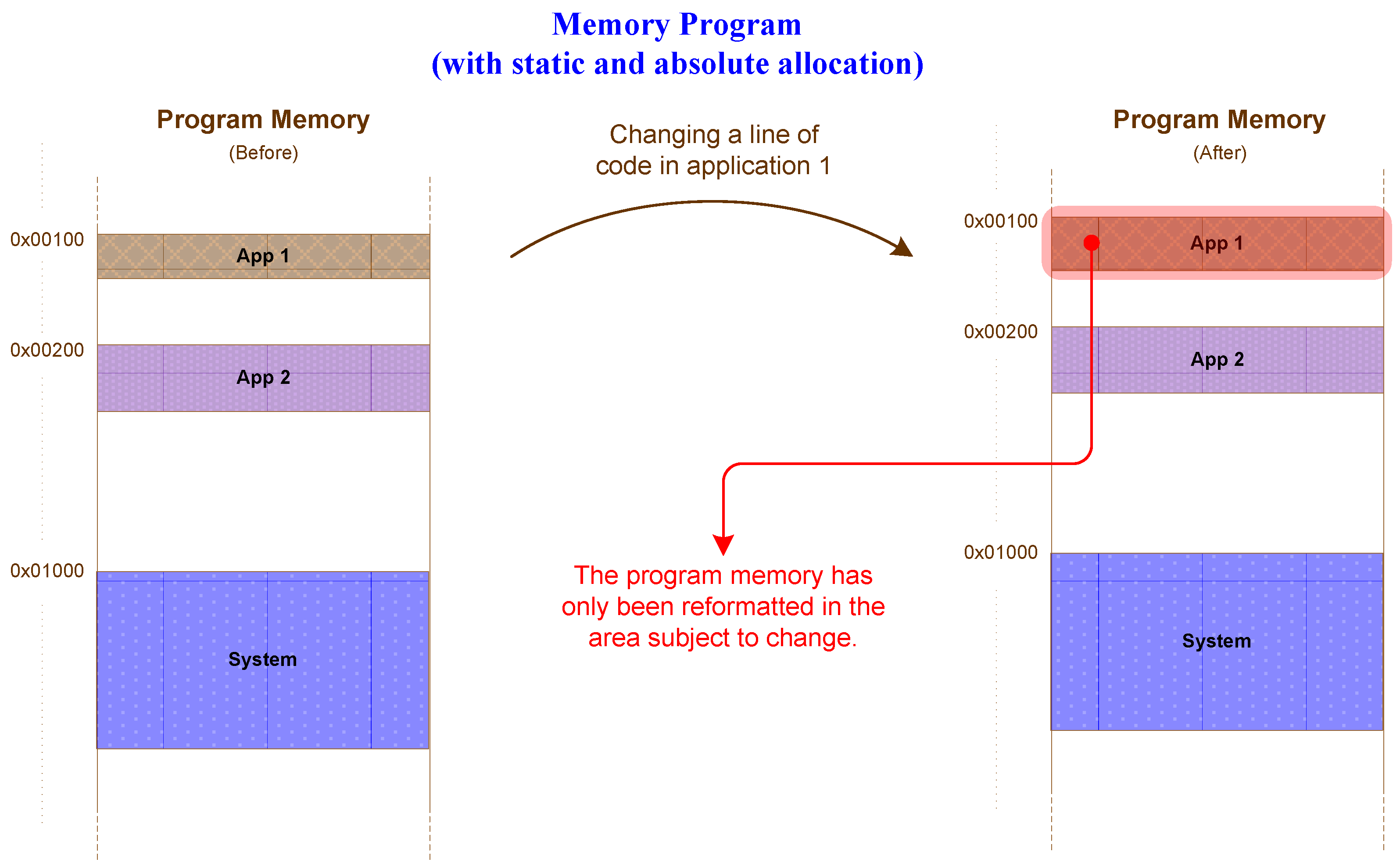
The firmware update mechanism for remote devices, described in [17], allows firmware updates to be performed during program execution without interruptions or reboots by updating only specific segments of the code in the program memory. This method, in addition to minimizing or eliminating downtime, substantially reduces the amount of data transmitted during the update process, making it a reliable approach for updating remote LoRaWAN devices. Utilizing the non-volatile memory (NVM) controller present in most microcontrollers on the market, the code segments to be updated are modified in the program memory during the runtime of different ongoing applications without compromising their operation. The use of static and absolute addresses in various application functions to locate and isolate code segments during compilation, as proposed in [17], enables precise identification of each function, simplifying the process of updating code blocks. This approach significantly enhances code organization by avoiding substantial changes to the existing code and ensuring that small modifications in specific functions affect only the associated allocated memory areas (Figure 2).
This process requires a well-designed system architecture and a complete understanding of the program memory map to avoid overlaps between functions or application code blocks, making it necessary to reserve additional memory space adjacent to each function to be implemented.
When compiling a firmware project using this method, after a minor bug correction or the inclusion of improved functionality, only the affected areas of program memory are reworked. This confines the altered code to a well-defined block of program memory, simplifying the update task. Consequently, only the changed code segment needs to be transmitted to the end device for the update.
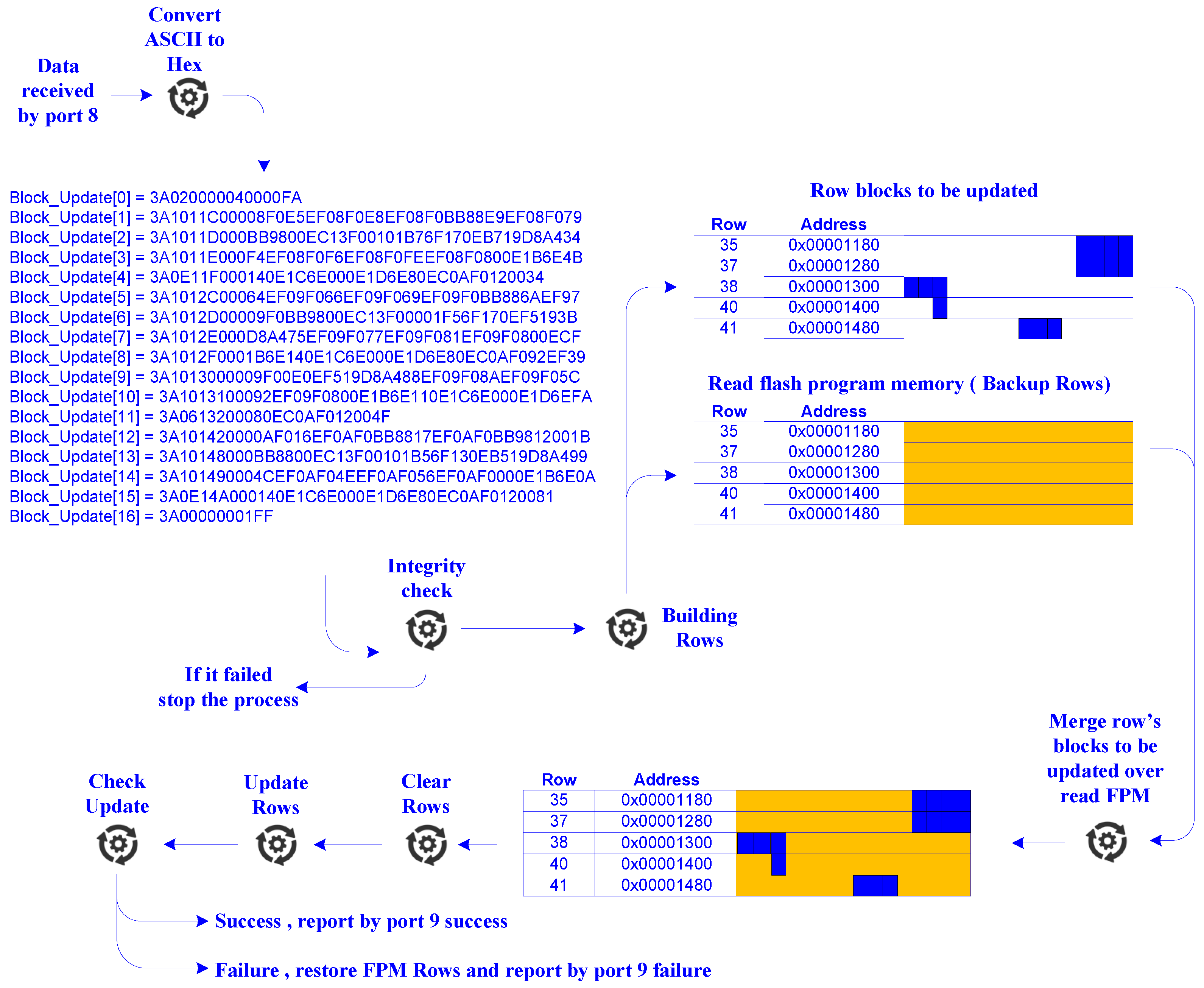
The update process (Figure 3) begins when the system receives a hexadecimal file in the Intel Hex format, containing the data related to the specific parts of the program code that have been updated. Upon receipt of the file or parts of the file, the system verifies the integrity and the completeness of the message. Once the integrity of the received file is verified, the system copies the file data to RAM, where it examines the received data to identify the code segments corresponding to each block of program memory, which is structured in rows. These segments are then mapped to the appropriate memory regions in the microcontroller based on the provided addresses. After identifying the code segments to be updated, the system reads the content of the corresponding program memory segments and stores them in the system’s RAM for backup purposes. Next, the system updates the code segments with the data retrieved from the update Intel Hex file. In the next step, the system updates the program memory by overwriting each code segment with the updated version, replacing the current version in the microcontroller’s flash memory. After updating each segment, the system verifies the writing process to ensure no errors occurred. Finally, the system signals the result of the update: if successful, a “Success” message is sent; otherwise, a “Failure” message is sent, indicating an issue during the update process, and the original memory rows and blocks are restored from the backup data.

3.3. Uplink and Downlink Configuration

To enable more efficient interaction between IoT end devices and the application server, the developed solution employs virtual communication ports to organize and handle data based on the type of information involved. LoRaWAN technology facilitates information routing through a port-based logical abstraction, providing an efficient data handling mechanism that organizes and routes information according to the associated communication port. The network server is equipped with the necessary tools to decode data based on the selected port. In the experiment described in this article, six communication ports are defined, as shown in Table 2.
The data sent by the end devices to the application server, in the uplink, undergo a protocol conversion at the network server to enable the application server to correctly interpret the binary format data sent. After conversion at the network server, the data are transmitted to the application server in ASCII format.
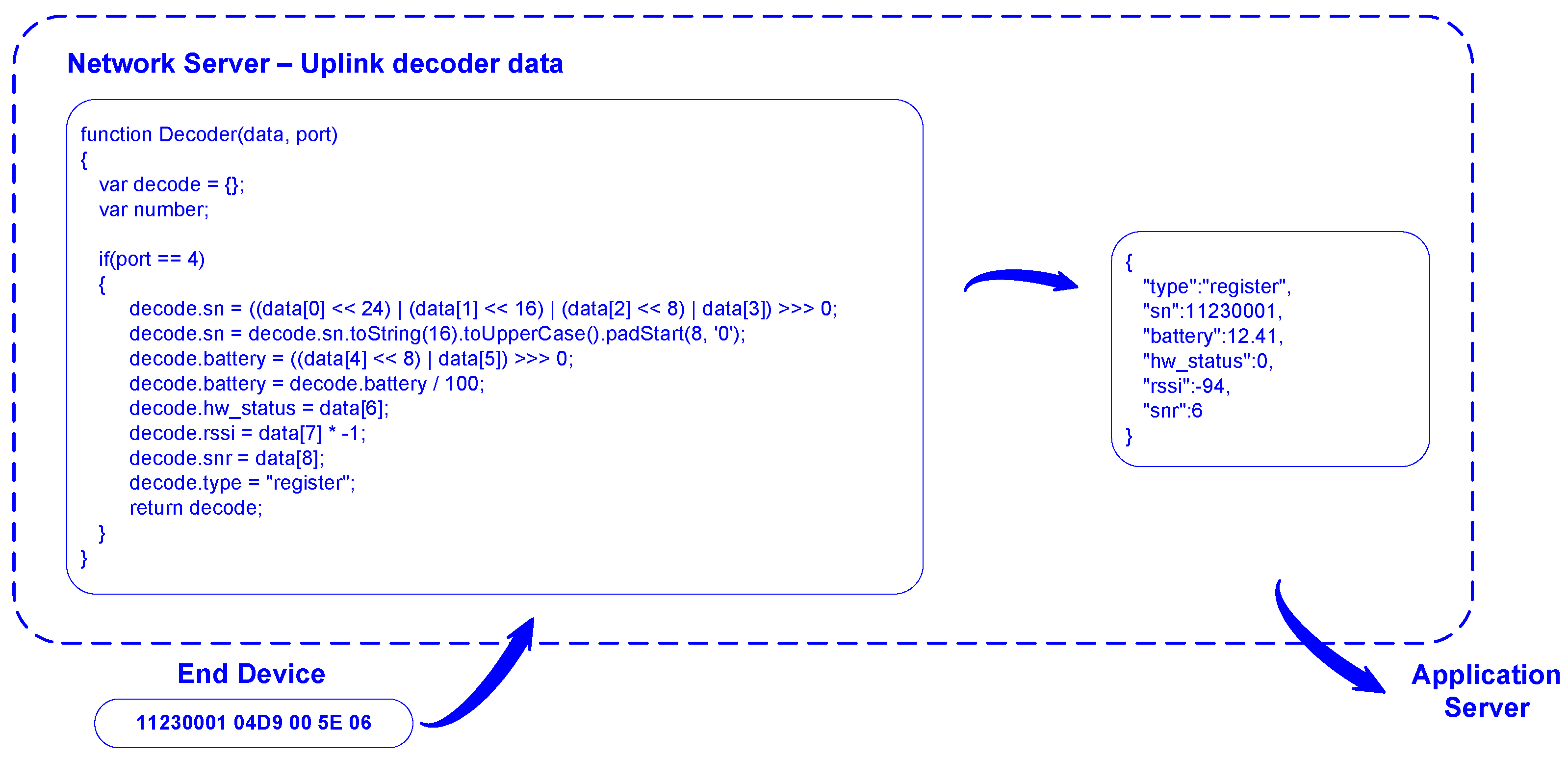
JavaScript is selected, among other data formatting options, to handle data in the network server. Depending on the communication port, information is filtered and processed differently. For example, if the end device sends the message shown in Figure 4, the JavaScript script decodes the received data from binary format and creates a new message in JSON format with fields corresponding to the message type, serial number, battery level, hardware status, received radio signal power level, expressed by the Received Signal Strength Indicator (RSSI), and signal quality using the signal-to-noise ratio (SNR) value (Figure 5).
On the other hand, whenever there are data available to be sent to the end devices in the downlink, the network server processes the information differently based on the selected communication port and forwards it to the respective end device. The first step in that process involves decoding the data received by the application server, while the second step entails encoding this information into binary format, in accordance with the communication protocol established between the end device and the network server.
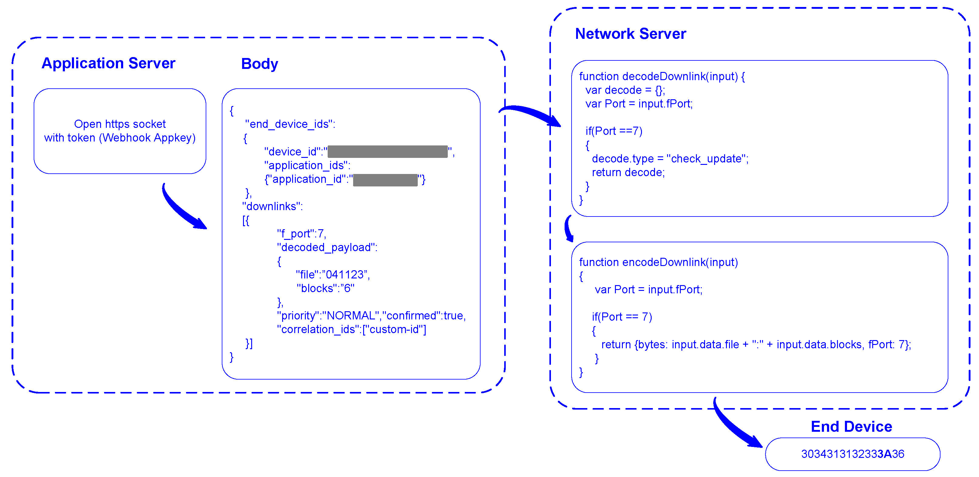
The downlink process implemented in this study is based on enhancing or altering the behavior of a web application or system using custom callbacks known as webhooks. A webhook is triggered by specific events, sending an HTTP request to a pre-configured URL. This mechanism allows the network server, upon receiving a message or command from an application server, to automatically send feedback data to the end device, thereby facilitating bidirectional communication and process automation. Figure 6 illustrates the implemented downlink process. Initially, the application server opens a TCP/IP socket with the network server. The message payload includes the data to be sent: the target end device ID, the network server application ID responsible for forwarding the information to the end device, the associated communication port, and the actual data, referred to as the payload. Figure 6 presents an example of this process, where the payload corresponds to the firmware update file name and the number of blocks contained in the file, which are transmitted via Port 7.

3.4. Application Server

Application servers play a crucial role in implementing an IoT system, being responsible for processing, storing and presenting data sent by end devices. The application server developed in this work is of the machine-to-machine (M2M) type, meaning there is no user web interface on the application server.
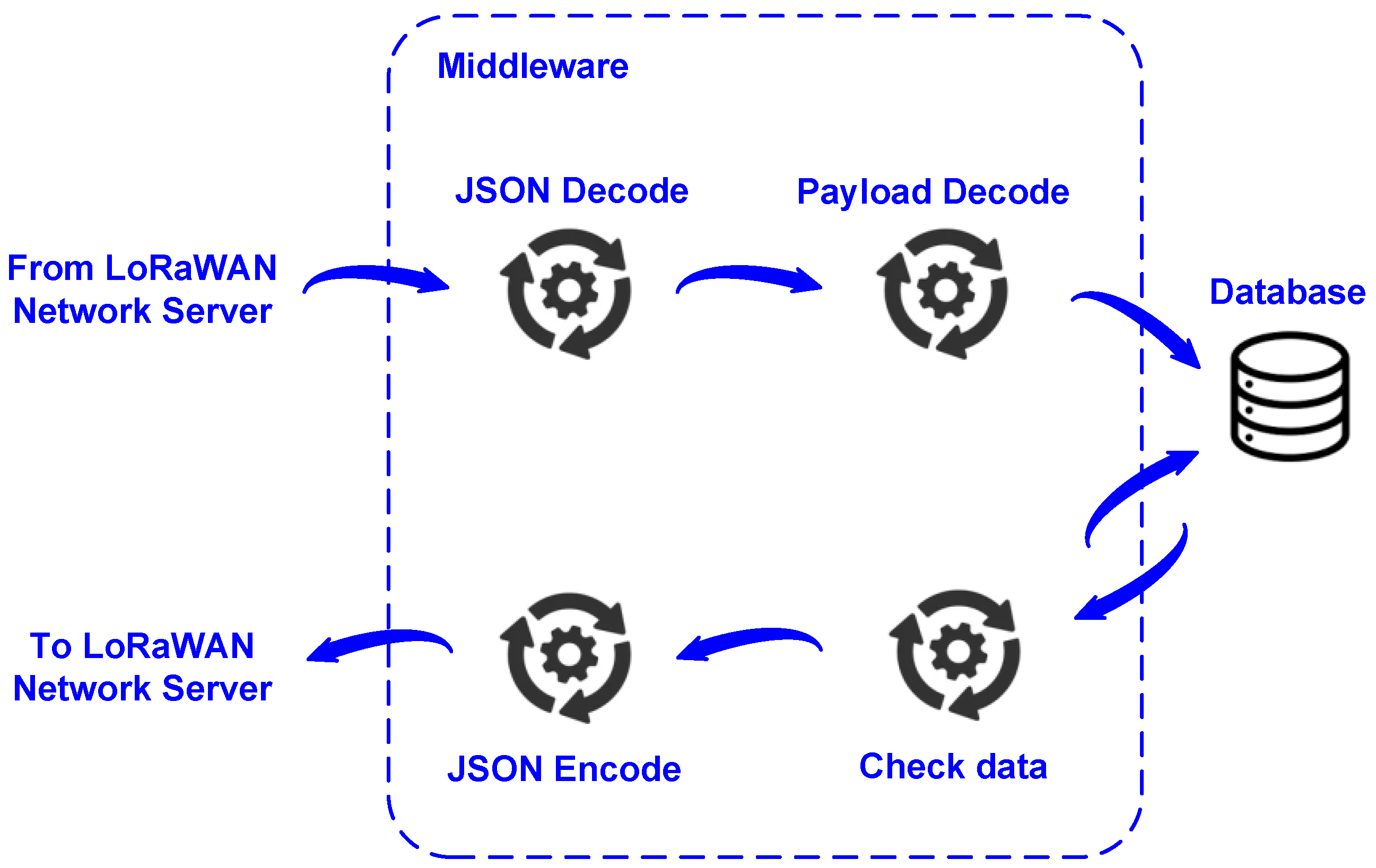
At the core of the application server is the middleware (Figure 7), which serves as a vital interface between the network server and the database. Upon receiving a JSON frame via HTTP POST method from the network server, the middleware extracts data from the frame fields. Based on the type of data received from the LoRaWAN network server, it performs specific and differentiated actions. The middleware is responsible for routing data from end devices; for example, if the received data pertain to device registration, Port 4, the middleware directs the data to the device registration table in the database. Conversely, if the data are related to an event, they are directed to the event registration table. Additionally, the middleware checks whether there are any data in the database to be forwarded to the end device that initiated the message reception by the network server. In the downlink, the middleware segments messages destined to end devices, ensuring they are formatted according to the maximum payload size supported by the LoRaWAN network (Table 1).

3.5. Implementation of the Proposed System

To validate the proposed firmware update mechanism, a system comprising three components was implemented: an RFID-based access control electronic device equipped with LoRaWAN communication, The Things Network server, and a proprietary application server for information management.
The electronic device includes a LoRa radio transceiver and a LoRaWAN stack for communication with the network server. The LoRaWAN network server acts as an interface between the remote end devices and the application server. Once registered and configured on the network server, remote end devices gain network access to forward information to the application server. The application server consists of middleware and a database, with the middleware acting as an intermediary between the network server and the database.
This system implementation aims to evaluate the performance of the proposed firmware update process, demonstrating a reduction in the amount of data required for updates. The proposed solution also eliminates the need for image reconstruction on IoT devices, removes bootloaders, utilizes available resources efficiently, significantly reduces downtime, and creates a less complex system accessible to all.

3.5.1. Hardware

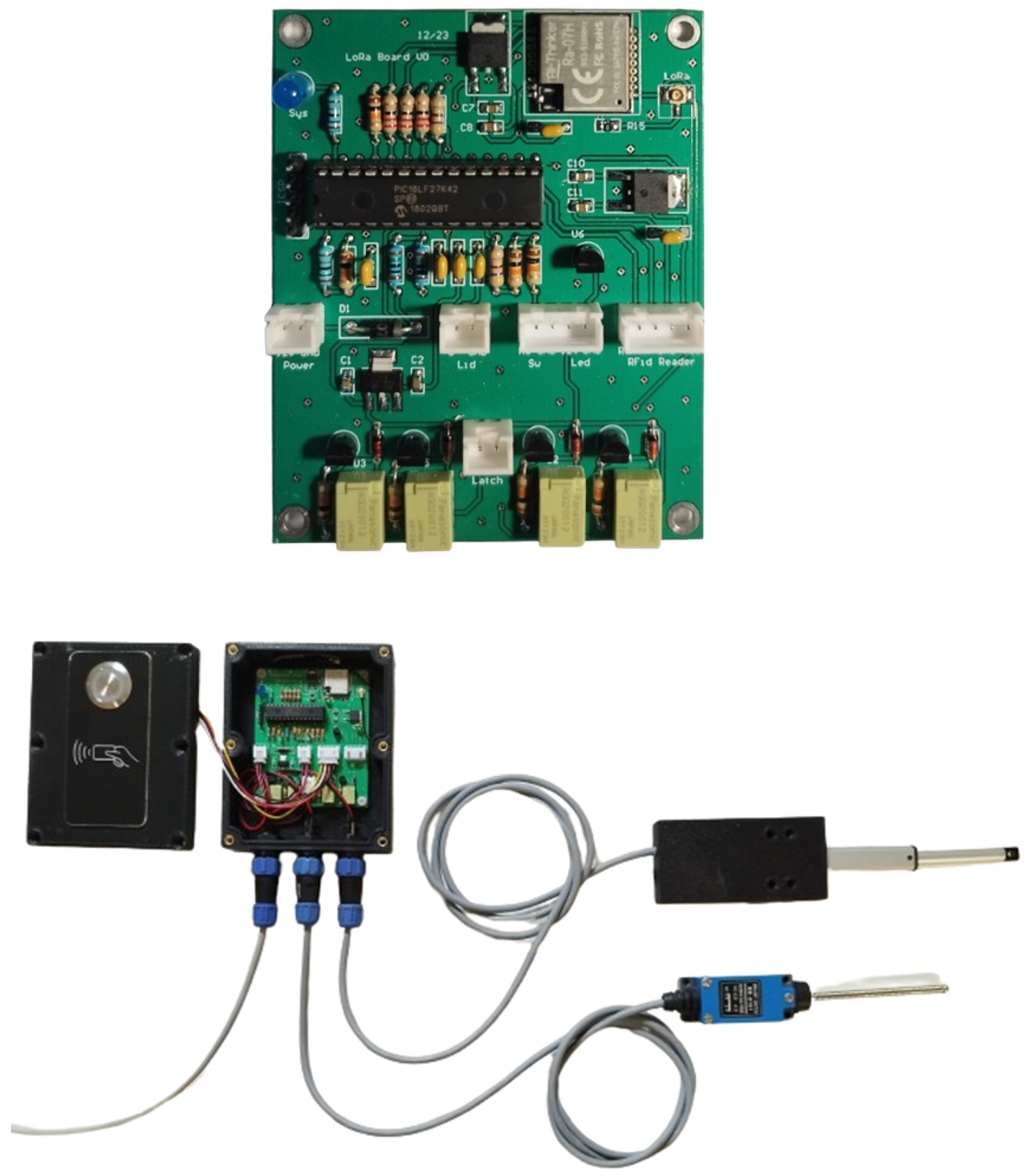
In order to validate the proposed update technique, an electronic device for RFID access control was designed and implemented, equipped with LoRaWAN communication. The PIC18LF27K42 microcontroller [18] was chosen to control the electronic device, while the LoRa radio transceiver RA-07H [19] was selected to provide LORAWAN communications due to its stack accessible via UART and AT commands [20]. The electronic device was designed to be energy efficient, with a consumption of less than 10 µA in sleep mode. Figure 8 depicts the printed circuit board of the constructed electronic device, along with an image of the assembled hardware.

3.5.2. Firmware

The developed firmware testbed must consider the static and absolute allocation of functions in the microcontroller’s memory. Therefore, updating a functionality of the application only requires replacing that particular function, which is confined to a code block whose size is an integer multiple of the memory rows size. In the development of the firmware update method during runtime proposed in [17], a maximum update size of up to eight rows was considered, resulting in a very short update downtime of less than 30 ms for the considered maximum number of update rows.
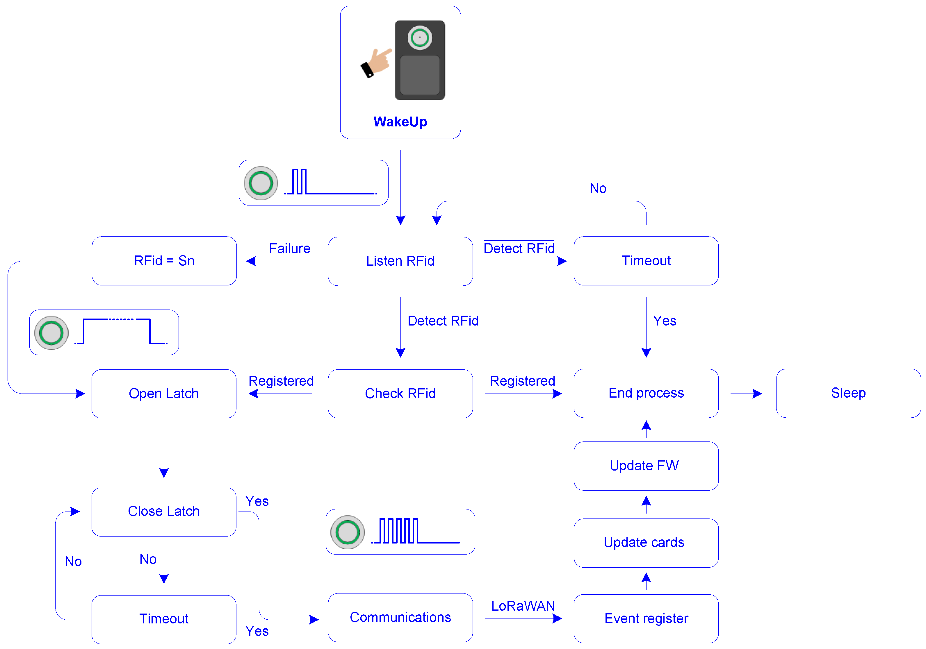
Figure 9 depicts the functional diagram of the implemented application. In its normal state, the device is in sleep mode. Upon detecting that the wake-up button is pressed, the device wakes up and activates the RFID card reader. If a valid RFID card is detected during the listening period, the device opens the electric latch; otherwise, it returns to low-power sleep mode. After reading a valid RFID card, the device activates the electric latch and waits for access. Upon completion of this procedure, the device enables communications to log that event in the application server. Thereafter, the device checks for instructions to update new RFID cards, which may include removing or inserting new codes, and finally it checks for firmware update instruction.
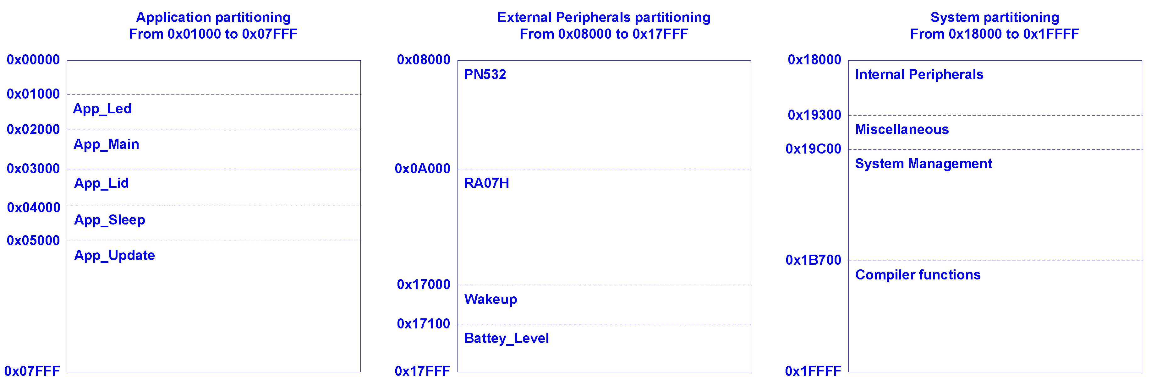
The functional architecture of the proposed system can be divided into three functional blocks: applications, management of external peripherals, namely the RFID card reader and LoRaWAN transceiver, and system functions, encompassing internal peripherals and system management. For this purpose, three partitions were created in the program memory (Figure 10). The first is dedicated to applications, the second to external peripherals, and the third to the system, which includes management of the applications of the microcontroller proposed in this article, interface with internal peripherals, and support functions for applications.
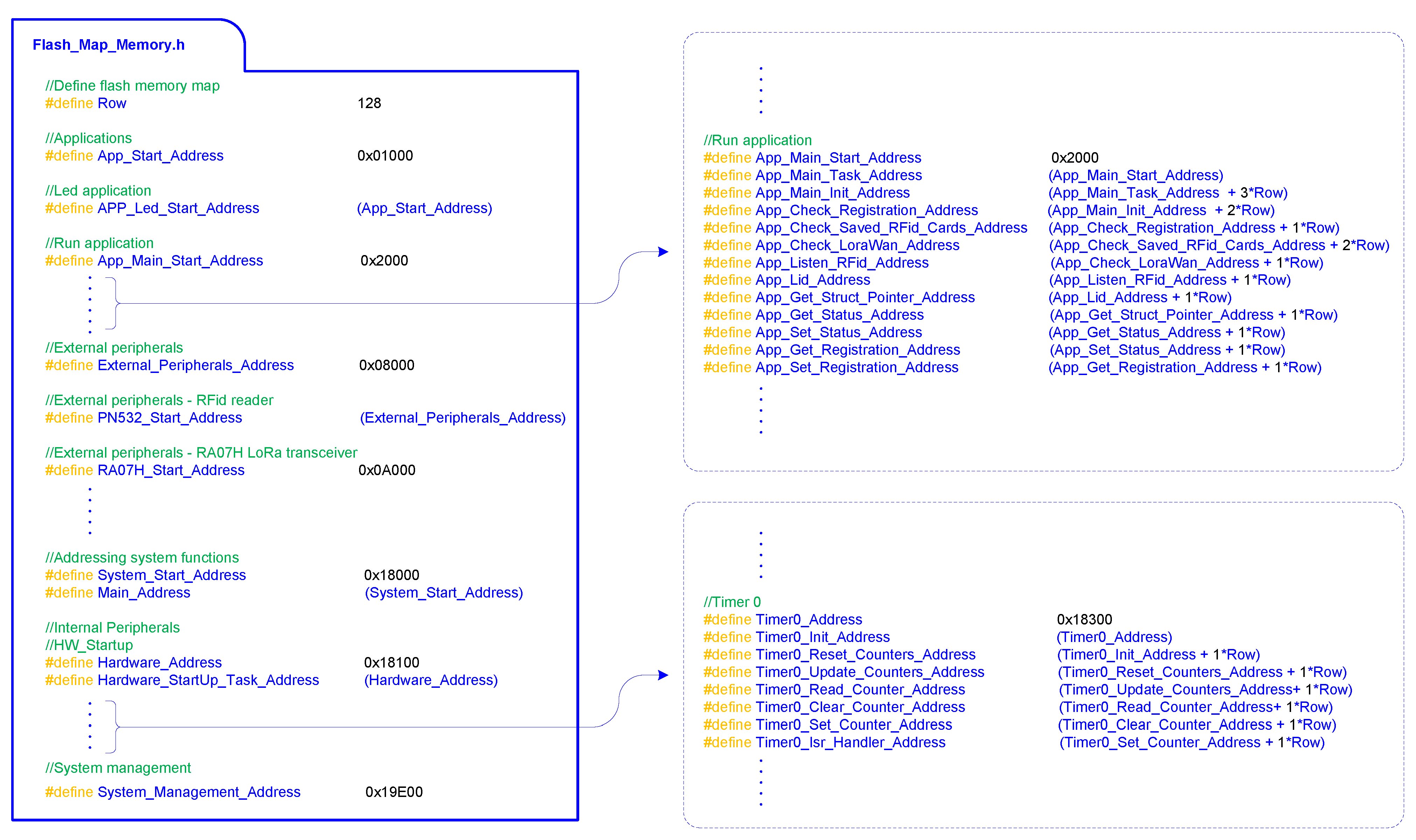
Upon setting the program memory map, the function addresses were statically allocated across the corresponding partitions (Figure 11). The program’s memory map design considers the possibility that a function might require more memory in the future. Therefore, it was determined that the size allocated to each function should be increased by approximately 25% to accommodate extensions on the functions size, as shown in Expression (1). Using this expression, it was verified that the number of program memory rows assigned to each function corresponds to the integer value obtained by multiplying the function size in bytes by 1.25, divided by the size in bytes of a memory row plus 1. This approach aims to ensure a reserve of about 25% of the program memory for future updates.
Memory Allocation [ row ] = INT Function Size × 1.25 Row Size + 1
In the developed system, it was considered that the device was of Class A, meaning a device that can only receive data from the network server in response to an uplink. Additionally, a data processing mechanism was implemented for received messages, differentiated based on virtual communication port usage. In the proposed firmware update scenario, the fact that information arrives through the firmware update-associated communication port is sufficient to trigger the firmware update mechanism, thus dispensing with the frame initialization tag.
To validate the proposed remote firmware update process during runtime presented in this article, a correction was made for an error detected after the release of the last firmware version. After the installation of the end devices, it was found that energy consumption was higher than expected. Upon analyzing the code, it was found that the debug LED (development support LED, see Figure 8, blue LED) was not disabled before release, resulting in extra energy consumption and thereby reducing battery life.
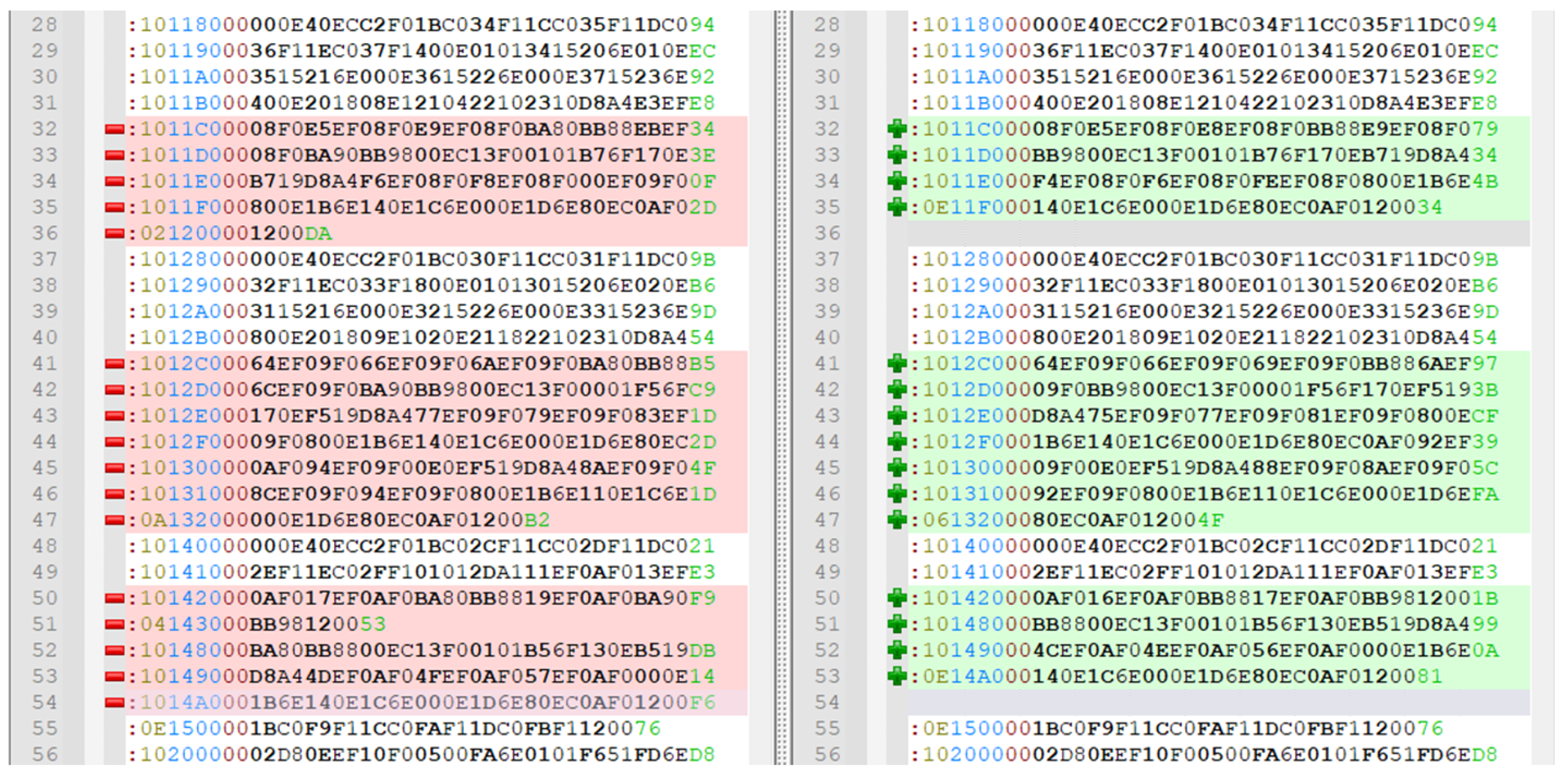
Figure 12 shows the changes that the new version of the firmware produces after it is compiled compared to the initial firmware version (SBW_new.hex, green side) compared to the old file (SBW_old.hex, red side).
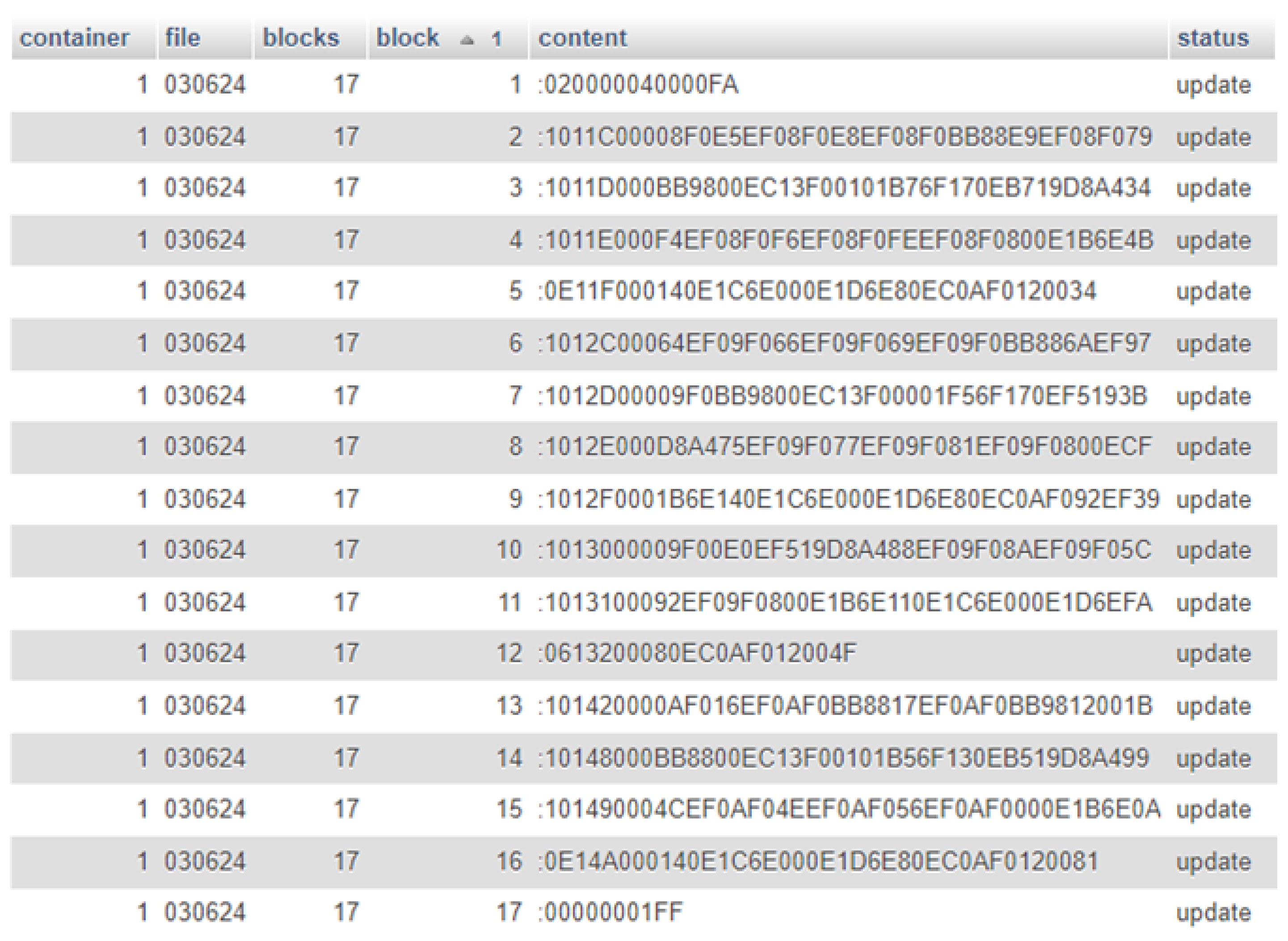
Figure 12 shows that, in the example under analysis, to update the end devices firmware via the LoRaWAN network, it is sufficient to send only 17 records of the Intel Hex file. The first record indicates the most significant address of the program memory block where changes will be made, the last record indicates the end of file, and the remaining 15 records are associated with the code update information. The next step involves inserting the hexadecimal file records to be sent to the end devices into the database. For this purpose, the database contains a table named “fw_update”, where we insert the IDs of the end devices we intend to update, the update name, the total number of records to update, the index of each record, the content of each record, and finally a variable with update execution status. Figure 13 illustrates the database with the records inserted according to the defined criteria above.
After inserting the update firmware records to update into the database, the first time that the end device performs an uplink communication, the middleware marks that event occurrence and checks for the existence of firmware update records. If a pending update is available, the process of sending the update file is initiated by sending the file name and the number of records to update via downlink on Port 7, followed by sending the firmware update records via downlink on Port 8.
Thereafter, the TTN network server places these data in a transmission queue for the corresponding end device. During the next uplink event, the content of the records to be updated is sent from the network server to the end device via the LoRaWAN gateway. The data are then forwarded to the UART serial communication port, which routes the information to the PIC18LF27K42 microcontroller [18]. Upon receiving the file name and the number of records to be updated through communication Port 7 (Figure 14), the microcontroller activates the firmware update application and prepares the device to receive an Intel Hex File for firmware update, which, for the considered example, comprises 17 records.
Upon receiving the firmware update records via communication Port 8 (Figure 15), the microcontroller stores each record in the corresponding data structure, which supports up to 64 update records. When the last record is received (end of file), the microcontroller signals the firmware update application to proceed with the update process.
The firmware update process is initiated by checking the update name. If the update was already performed previously, it is discarded, and the device signals that the current version is up to date; otherwise, the update process proceeds to the next step, which involves verifying the received data. At this stage, the integrity of each record of the received update file is verified using the checksum error control mechanism. Once the data integrity of each incoming record is validated, the update process fills a backup data structure similar to the one used on program’s memory. The data are organized into rows of 128 bytes each in the case of the PIC18LF27K42 microcontroller [18].
The update process is designed to update up to eight rows or 1024 bytes. After restructuring the data into rows, the next step involves populating each row of the new data structure with existing program memory data corresponding to that row. Additionally, a copy of the program memory data rows is stored for recovery purposes in case of failure.
With the firmware update data structure prepared, the next step involves formatting each of the rows to be updated. This formatting consists of erasing the contents of these rows and filling them with the hexadecimal value 0xFF. Subsequently, each row of the program memory is updated with the data from the received records. Finally, a verification of the updated rows is performed to ensure that the content written into the program memory exactly matches what was intended. This involves verifying whether the program memory content specified in the update record addresses corresponds to the received update record data. If the verification is successful, the update process signals Success; otherwise, it signals Failure and restores the previous firmware version. Figure 16 graphically illustrates the described update process.
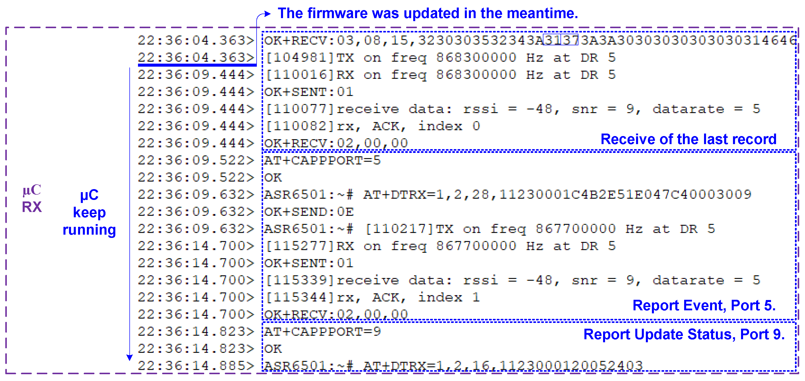
As depicted in Figure 16, the update process is finalized with the transmission of the update status by the end device. The update message includes the filename being updated and its status, either success (Code 3) or failure (Code 4). Figure 17 illustrates the message sent by the microcontroller to the RA-07H radio transceiver and its reception by The Things Network server through Port 9.
The network server, upon receiving the firmware update status message, forwards it to the application server. There, the middleware interprets the message and update the state of each firmware update record from ‘update’ to the state indicated by the update message, either ‘updated’ or ‘failure’.
From the analysis of the debug report of the UART TX and RX pins of the microcontroller and the RA-07H radio transceiver, correlated with the data traffic on the network server, it was observed that the time required for the update process depends on the number of records to be updated due to the characteristics of the LoRaWAN network.
It is also noted that the firmware update occurred during runtime without the need to restart the end device after completion of the update and without any perceived downtime, as depicted in Figure 18 and Figure 19.

4. Results

To evaluate the performance of the firmware update method proposed in this paper, five distinct firmware updates were carried out using the end device and application previously described. The updates performed varied in size regarding the number of records in the Intel Hex File and the number of rows to be updated in the microcontroller’s program memory.
The analysis of the proposed method’s implementation was conducted separately in two distinct temporal domains. The first domain pertains to the time required for transmitting the Intel Hex File update records in the LoRaWAN network downlink, and the second domain refers to the actual update process time on the end device’s microcontroller.
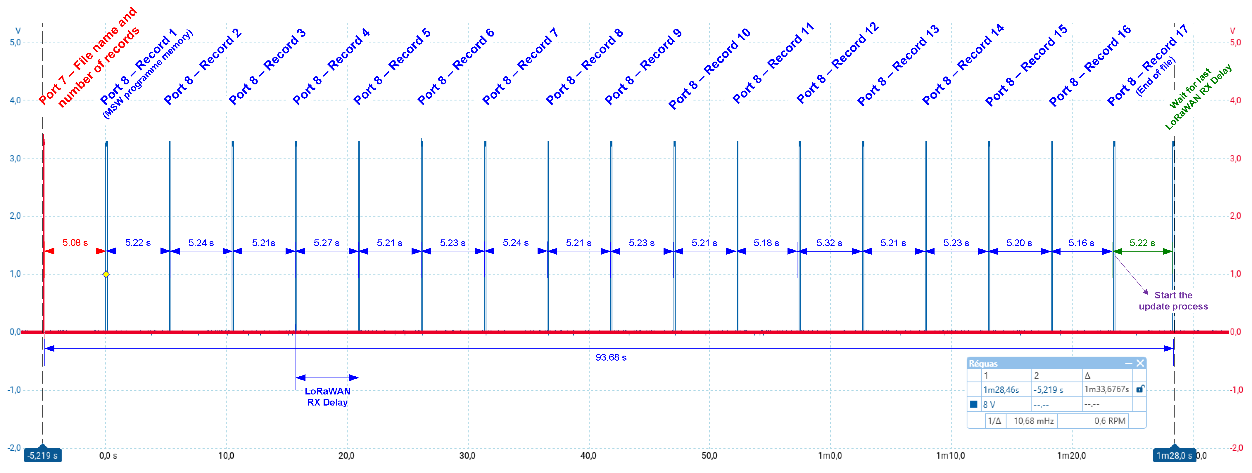
Figure 20 presents the time diagram related to the update exemplified in the previous section, corresponding to Update #3 in Table 3, where the reception times of frames sent by the network server to the end device are shown. We can observe the reception, through Port 7, of the information related to the update to be carried out, which includes the name and the number of records to be received. Following this, the reception of different blocks of the update file is observed, with the transmission ending upon receiving the end of file block. The time associated with transmitting the firmware update information through the LoRaWAN network was 93.66 s.
From the analysis of the reception times of the records, it was found that the transmission time of an update can be determined using Expression (2), with the value of 5.22 s corresponding to the average value of the reception window (RX_Delay) (Figure 20).
Transmission time of update file [ s ] = Intel Hex File Number of Records × 5.22
From the results obtained from the firmware updates performed, it was concluded that the greatest time constraint is associated with the data transmission time over the LoRaWAN network, which depends on the size of the RX Delay window operating in Class A. The transmission time is thus dependent on the number of records to be updated, while the time spent on the update process in the microcontroller mainly depends on the number of rows to be updated (Table 3).
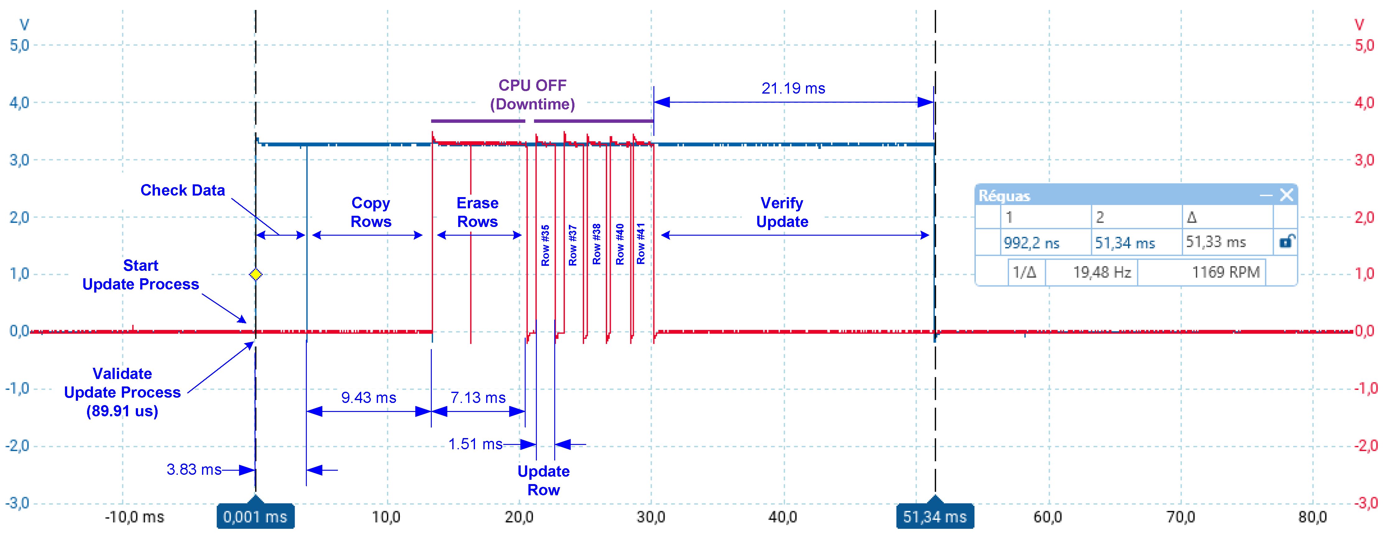
To assess the times associated with the different tasks involved in the microcontroller update process, mechanisms were implemented to signal the start and end of each task by activating/deactivating IO pins of the microcontroller.
Figure 21 shows the timeline diagram for executing the different stages of the proposed update process for Update #3. These stages include data integrity verification, preparation of new rows for update, copying rows for recovery scenarios, erasing old rows, inserting new data, and finally verifying the update process. The overall firmware update process is represented by the blue line in Figure 21, while the flash memory write operations are depicted by the red line. Each stage begins when the corresponding IO pin is set to a high level and ends when it is set to a low level. Analysis of the results for the firmware update mechanism proposed, for Update #3, indicates that the process takes 51.33 ms to complete all stages, with a downtime of 16.88 ms.
The findings of this study confirm that the proposed firmware update method during runtime, without IoT device reboot, offers significant advantages. Firstly, a substantial reduction in device downtime was observed, which is beneficial for applications requiring high availability. Additionally, there was a decrease in energy consumption during the update process compared to updating a complete firmware image, preserving the autonomy of Class A IoT devices. The proposed approach also minimizes the amount of data transmitted compared to updating a complete firmware image, thereby reducing the communication network load and concentrating the update process effort more on the end device, simplifying its implementation and operation. The reduction in computational load related to the update process is achieved by eliminating the reconstruction of the firmware image on the end device, optimizing resources both on the device side through more efficient memory usage and on the network side, which shows improved performance due to reduced traffic load.
When comparing with related works, it was noted that, contrary to the idea advocated by Dirk Pesch et al. [3], the proposed method is efficient for the LoRa Alliance Class A data transmission mechanism, where downlink follows an uplink. Despite the LoRa Alliance specifications [21] for FUOTA, the proposed method utilizes the network server application layer, making the update process less complex and more agile. Charilao et al. [5] suggest improvements in the update process using multiple gateways; however, the method proposed in this article does not require changes to the existing network, except in scenarios without coverage. We partially agree with Guinee, C. [22], who argues that Class B performs better in terms of transmission and energy efficiency for complete firmware image updates. However, since the proposed method significantly reduces the amount of data, it preserves network capacity and improves energy efficiency by drastically reducing the active time associated with the update process. In contrast to the study by Hess, Tim [9], which suggests benefits in switching to Classes B or C, the implemented method demonstrates a significant reduction in downtime of 16.88 ms compared to the 42.48 s described in [9], without the need for a class change. This is primarily due to the method not requiring firmware image reconstruction from delta segments (18.57 s). Furthermore, there is a significant reduction in energy consumption as only 643 bytes needed to be transferred compared to the full firmware image size of 108 kBytes required for the update, a data reduction of 99.42%. Additionally, our method aligns with the objectives of Lee, B. [6], where it aims to simplify the firmware update process without resorting to blockchain while maintaining update integrity and security. Finally, concerning the study by Jaouhari, S. E. [23], our method eliminates the use of a bootloader, allowing firmware updates during runtime, further accelerating the process.
Table 4 provides a comparative analysis between the different methods discussed in related works and the proposed method. Our method stands out for maintaining the device class type and substantially reducing downtime, primarily due to the Self-Programming-based update method during runtime, eliminating the need for rebooting after the update. Multicast distribution-based methods are advantageous for mass updates but have disadvantages such as high transmission time and the need for device reboot after updating. Packet transmission methods resulting from the difference between the original and updated firmware image (Delta Update) optimize transmission time, but reconstructing the firmware image from deltas results in high downtime for high-availability systems and requires more resources, especially memory and computational effort.
Regarding energy efficiency, the proposed method stands out significantly. This efficiency gain is due to the fact that only the blocks of program code that need to be modified or added are transmitted. This metric aligns with Delta Update methods, which are noticeably more efficient than those requiring the entire firmware image to be updated. From the performance evaluation trials of the proposed system (Table 3), the update process achieved 100% efficiency. Charilao et al. [5] also reported 100% efficiency in network scenarios with more than 23 gateways. In terms of scalability, the proposed method does not have the capacity to handle the simultaneous update of thousands or millions of devices, in contrast to the analyzed methods based on multicast transmission topologies.

5. Conclusions

The method proposed in this study represents a significant advancement in firmware updates for LoRaWAN Class A devices. By implementing code segment-based updates during runtime, we substantially reduced device downtime, which is crucial for maintaining high availability in critical applications. Additionally, the reduction in energy consumption during the update process helps preserve device autonomy, which is critical for remote and hard-to-access units. Furthermore, it results in a significantly higher energy efficiency compared to existing solutions.
The proposed firmware update mechanism is compatible with a wide range of microcontrollers, ensuring data integrity throughout the process. Its robustness makes it particularly well-suited for applications such as smart agriculture, smart cities, smart metering, and other use cases relying on LoRaWAN infrastructure. These features are especially relevant in environments where continuous and efficient updates of remote devices are required.
The proposed approach stands out due to the reduction in transmitted data, alleviating the communication network’s overhead and increasing overall system efficiency. The simplicity and agility of the update process are achieved by focusing efforts on the network server’s application layer and on the IoT device’s update process, avoiding the complexity and inflexibility of the LoRa Alliance’s FUOTA specifications. This method not only simplifies implementation and operation but also ensures that updates can be performed without changes to the existing network infrastructure.
However, some limitations need to be addressed. The proposed method has limitations regarding the program memory size to be updated, which is limited to 1024 bytes. Additionally, it is also incompatible with operating systems and intermediate hardware abstraction layers. In update failure scenarios, the proposed process is repeated in the next iteration in its entirety. As future work, we suggest classifying update failures to address this issue, for example, identifying whether the failure occurred due to a missing line (in this case, performing only the downlink of the missing line), whether a line did not pass the integrity test (verifying the integrity of the line on the application server), or whether the failure occurred in the verification process after writing to the program memory (which may indicate aging of the program memory and the need to allocate changes in another memory area).
Data compression algorithms can be integrated to further optimize the update process, while the implementation of advanced security protocols, such as end-to-end encryption, enhances system robustness in vulnerable environments.
Although the method described in this work focuses on peer-to-peer updates, making mass updates via multicast unfeasible, with appropriate adaptations and adjustments to the IoT device class, it can efficiently support multicast firmware updates, enabling scalable implementation in scenarios involving hundreds of devices. In summary, the proposed method offers significant potential for the aforementioned applications, providing an efficient, secure, and cost-effective solution for firmware updates in LoRaWAN Class A devices. It notably reduces downtime, improves energy efficiency, preserves network capacity, simplifies the update process, and enhances the reliability of IoT systems.

Author Contributions

Conceptualization, A.V. and B.P.N.; Formal analysis, V.D.N.S.; Investigation, B.P.N.; Methodology, B.P.N., V.D.N.S. and A.V.; Resources, V.D.N.S.; Writing—original draft, Bernardino Neves; Writing—review and editing, V.D.N.S. and A.V. All authors have read and agreed to the published version of the manuscript.

Funding

This research received no external funding.

Institutional Review Board Statement

Not applicable.

Informed Consent Statement

Not applicable.

Data Availability Statement

Data are contained within the article.

Acknowledgments

This work was financed by National Funds through the Portuguese funding agency, FCT—Fundação para a Ciência e a Tecnologia, within project LA/P/0063/2020. DOI 10.54499/LA/P/0063/2020|https://doi.org/10.54499/LA/P/0063/2020. This work was supported by the Portuguese Foundation for Science and Technology under the project grant UIDB/00308/2020 with the DOI 10.54499/UIDB/00308/2020|https://doi.org/10.54499/UIDB/00308/2020.

Conflicts of Interest

The authors declare no conflicts of interest.

References

  1. Jongboom, J.; Stokking, J. Enabling firmware updates over LPWANs. In Proceedings of the Embedded World Conference, Nuremberg, Germany, 27 February–1 March 2018; Available online: https://scholar.google.com/scholar_lookup?title=Enabling+firmware+updates+over+LPWANs&conference=Proceedings+of+the+Embedded+World+Conference&author=Jongboom,+J.&author=Stokking,+J.&publication_year=2018.
  2. Schäfer, B. LoRaWAN Firmware Update Over The Air—FUOTA. 2023. Available online: https://stackforce.com/en/about-us/news/LoRaWAN-firmware-update-over-the-air-fuota (accessed on 9 June 2024).
  3. Abdelfadeel, K.; Farrell, T.; McDonald, D.; Pesch, D. How to Make Firmware Updates over LoRaWAN Possible. In Proceedings of the 2020 IEEE 21st International Symposium on “A World of Wireless, Mobile and Multimedia Networks” (WoWMoM), Cork, Ireland, 15–18 June 2020; pp. 16–25. [Google Scholar] [CrossRef]
  4. Mavromatis, I.; Stanoev, A.; Portelli, A.J.; Lockie, C.; Ammann, M.; Jin, Y.; Sooriyabandara, M. Reliable IOT firmware updates: A large-scale mesh network performance investigation. In Proceedings of the 2022 IEEE Wireless Communications and Networking Conference (WCNC), Austin, TX, USA, 10–13 April 2022. [Google Scholar] [CrossRef]
  5. Charilaou, C.; Lavdas, S.; Khalifeh, A.; Vassiliou, V.; Zinonos, Z. Firmware Update Using Multiple Gateways in LoRaWAN Networks. Sensors 2021, 21, 6488. [Google Scholar] [CrossRef] [PubMed]
  6. Lee, B.; Lee, J.-H. Blockchain-based secure firmware update for embedded devices in an Internet of Things environment. J. Supercomput. 2016, 73, 1152–1167. [Google Scholar] [CrossRef]
  7. AN5554—LoRaWAN® Firmware Update over the Air with STM32CubeWL. 2023. Available online: https://www.st.com/resource/en/application_note/an5554-LoRaWAN-firmware-update-over-the-air-with-stm32cubewl-stmicroelectronics.pdf (accessed on 9 June 2024).
  8. Zwart, D. Firmware Updates over the Air for Lora Using Random Linear Network Coding. TU Delft Repositories. 2022. Available online: https://repository.tudelft.nl/islandora/object/uuid%3A60364987-404e-490c-857f-e5958df2c325 (accessed on 9 June 2024).
  9. Hess, T. Ultra-Low-Power Over-the-Air-Update in Secure LoRaWAN Networks. 2020. Available online: http://hdl.handle.net/2078.1/thesis:25146 (accessed on 9 June 2024).
  10. Mahfoudhi, F.; Sultania, A.K.; Famaey, J. Over-the-Air Firmware Updates for Constrained NB-IoT Devices. Sensors 2022, 22, 7572. [Google Scholar] [CrossRef] [PubMed]
  11. Heeger, D.; Garigane, M.; Tsiropoulou, E.E.; Plusquellic, J. Secure LoRa Firmware Update with Adaptive Data Rate Techniques. Sensors 2021, 21, 2384. [Google Scholar] [CrossRef] [PubMed]
  12. Stokking, J. Firmware Updates over Low-Power Wide Area Networks. The Things Network. 2017. Available online: https://www.thethingsnetwork.org/article/firmware-updates-over-low-power-wide-area-networks (accessed on 9 June 2024).
  13. Catalano, J. LoRaWAN Firmware Update Over-The-Air (FUOTA). J. ICT Stand. 2021, 9, 21–34. [Google Scholar] [CrossRef]
  14. LoRa-Alliance. RP002-1.0.4 Regional Parameters. 2022. Available online: https://resources.lora-alliance.org/technical-specifications/rp002-1-0-4-regional-parameters (accessed on 9 June 2024).
  15. The Things Network. The Things Network. Available online: https://www.thethingsindustries.com/docs/integrations/ (accessed on 12 October 2024).
  16. ETSI EN 300 220-2 V3.2.1; Short Range Devices (SRD) Operating in the Frequency Range 25 MHz to 1000 MHz; Part 2: Harmonised Standard for Access to Radio Spectrum for Non Specific Radio Equipment. ETSI: Sophia Antipolis, France, 2018. Available online: https://www.etsi.org/deliver/etsi_en/300200_300299/30022002/03.02.01_60/en_30022002v030201p.pdf (accessed on 6 June 2024).
  17. Neves, B.P.; Santos, V.D.N.; Valente, A. Innovative Firmware Update Method to Microcontrollers during Runtime. Electronics 2024, 13, 1328. [Google Scholar] [CrossRef]
  18. Microchip Technology Inc. Low-Power High-Performance Microcontrollers with XLP Technology. PIC18(L)F26/27/45/46/47/55/ 56/57K42, Datasheet. 2021. Available online: https://ww1.microchip.com/downloads/aemDocuments/documents/MCU08/ProductDocuments/DataSheets/PIC18%28L%29F26-27-45-46-47-55-56-57K42-Data-Sheet-40001919G.pdf (accessed on 16 May 2024).
  19. RA-07H Datasheet. 2019. Available online: https://docs.ai-thinker.com/_media/lora/ra-07h_data_sheet_en.pdf (accessed on 17 May 2024).
  20. ASR650X at Command Introduction. 2024. Available online: https://www.hoperf.com/uploads/ASR650XATCommandIntroduction-20190605_1695629825.pdf (accessed on 12 October 2024).
  21. Lora Alliance. Lora Alliance Enhances LoRaWAN Protocol with New Specifications to Support Firmware Updates over the Air. LoRa Alliance®. 2018. Available online: https://lora-alliance.org/lora-alliance-press-release/lora-alliance-enhances-LoRaWAN-protocol-with-new-specifications-to-support-firmware-updates-over-the-air/ (accessed on 9 June 2024).
  22. Guinee, C. Efficient Firmware Update Transmission for LoRa Low Power Wide Area Technology. 2019. Available online: https://publications.scss.tcd.ie/theses/diss/2019/TCD-SCSS-DISSERTATION-2019-013.pdf (accessed on 9 June 2024).
  23. Jaouhari, S.E.; Bouvet, E. Toward a generic and secure bootloader for IoT device Firmware Ota Update. In Proceedings of the 2022 International Conference on Information Networking (ICOIN), Jeju-si, Republic of Korea, 12–15 January 2022. [Google Scholar] [CrossRef]
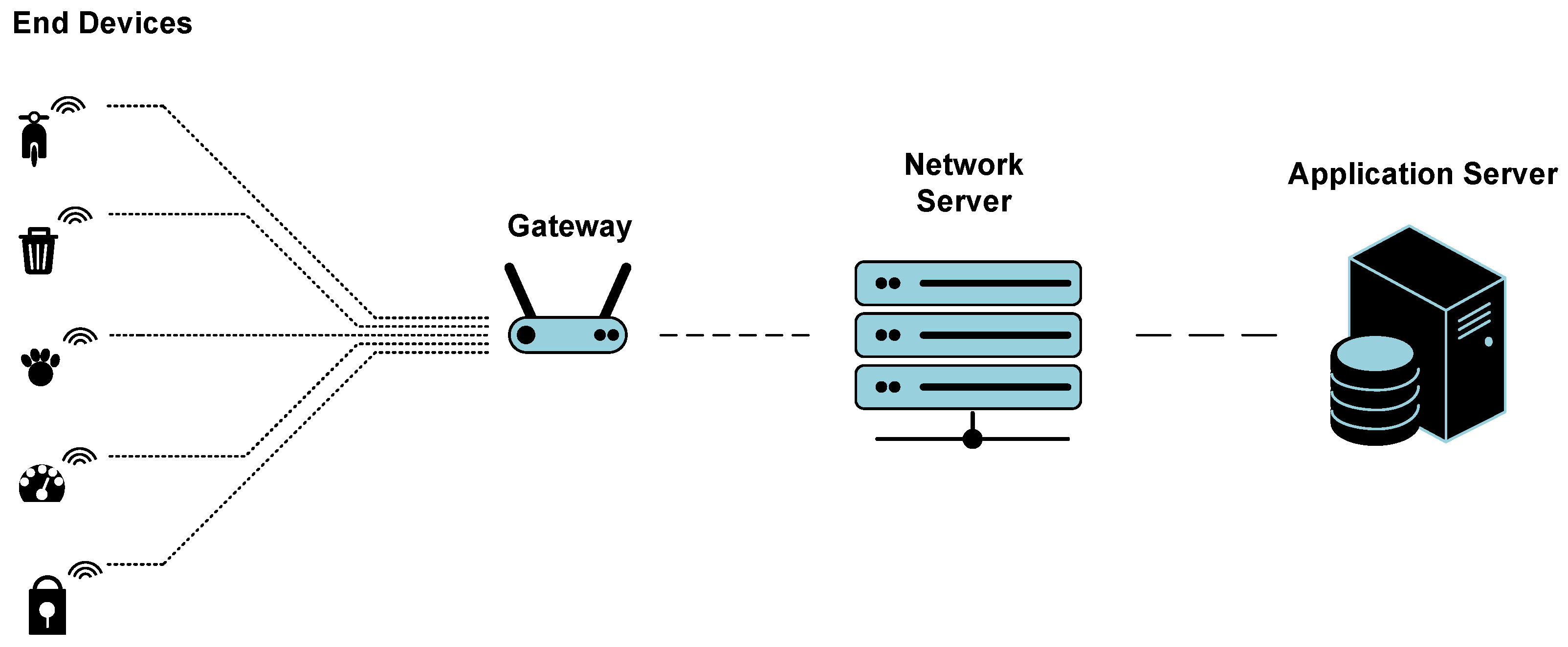
Figure 1. Typical architecture of the LoRaWAN network.
Eng 05 00137 g001
Figure 2. Static and absolute allocation of project functions.
Eng 05 00137 g002
Figure 3. Update Process During Runtime.
Eng 05 00137 g003
Figure 4. Protocol conversion in the LoRaWAN network.
Eng 05 00137 g004
Figure 5. Decoding of uplink data by the network server.
Eng 05 00137 g005
Figure 6. Implemented downlink process based on webhook.
Eng 05 00137 g006
Figure 7. Graphical representation of the middleware function.
Eng 05 00137 g007
Figure 8. Implemented electronic device.
Eng 05 00137 g008
Figure 9. Functional diagram of the implemented application.
Eng 05 00137 g009
Figure 10. Distribution of the three partitions in program memory.
Eng 05 00137 g010
Figure 11. Segment of the Flash_Memory_Map.h file.
Eng 05 00137 g011
Figure 12. Changed program memory area viewed from Intel Hex File.
Eng 05 00137 g012
Figure 13. Insertion into the fw_update table of the database, the records to be updated.
Eng 05 00137 g013
Figure 14. Screenshot of the data log from the TX pin of the RA-07H radio transceiver, Port 7.
Eng 05 00137 g014
Figure 15. Screenshot of the data log from the TX pin of the RA-07H radio transceiver, Port 8.
Eng 05 00137 g015
Figure 16. Graphical representation of the firmware update process during runtime.
Eng 05 00137 g016
Figure 17. Sending the firmware update status message.
Eng 05 00137 g017
Figure 18. Timestamps of UART TX communication activities from RA-07H radio transceiver.
Eng 05 00137 g018
Figure 19. Timestamps of UART RX communication activities from RA-07H radio transceiver.
Eng 05 00137 g019
Figure 20. Time diagram of the LoRaWAN downlink process of the update records.
Eng 05 00137 g020
Figure 21. Time diagram of the firmware update process during runtime.
Eng 05 00137 g021
Table 1. Spreading Factor (SF), Time on Air, (Adaptive) Data Rate, and Payload Size.
SFToA [ms]Data Rate [bps]Sensitivity [dBm]Energy [J]Max Payload [bytes]
122430244.14−136.51.38951
111310447.59−134.00.73851
10706813.80−131.50.34751
93381464.80−129.00.184115
82142604.10−126.50.103212
71194557.20−124.00.057212
BW—125 kHz, Payload—51 bytes, CR 4/6, Header enable and CRC on. Credits: https://www.semtech.com/design-support/lora-calculator (accessed on 9 June 2024).
Table 2. Classification of information type based on communication port.
PortData Type
4Device registration
5Event signaling
6Insertion or removal of RFID cards
7Firmware update check
8Firmware file request
9Update status signaling
Table 3. Impact assessment of completing firmware update of different sizes.
ParameterUpdate #1Update #2Update #3Update #4Update #5
Intel Hex File records66175710
Updated rows in the uC flash13578
Intel Hex File size (bytes)1941986432373372
Updated bytes in the uC flash6364226876128
Average transmission time of the update file using TTN (s)37.6037.0096.40317.2065.00
Average transmission time between records (s)5.375.285.355.465.91
Overall update process (ms)24.1237.451.3368.1272.75
Check data integrity task (ms)1.811.233.8314.192.21
Copy rows task (ms)1.756.719.435.9118.45
Erase rows task (ms)1.554.367.1310.0111.34
Update row task (ms)1.375.619.7514.9116.77
Verify update task (ms)17.6419.4921.1923.1023.98
Downtime (ms)2.929.9716.8824.9228.11
Table 4. Comparison table between several firmware update methods present in the literature.
MethodDirk Pesch et al. [3]Charilao et al. [5]Hess, Tim [9]Heeger, D. [11]Proposed System
Transmission topologyMulticastMulticastMulticastN. A.Peer to Peer
End device classCCCN. A.A
Memory update typeFull imageFull imageDeltasFull imageSegments
Firmware Update Size (kB)10010015.81280.641
Update firmware image ratio [%]100.00100.0011.68100.000.60
Transmission data records time (min)32[DR5]1140[DR5]5[DR5]16[DR6]1.61[DR5]
Update typeBootloaderBootloaderBootloaderDual BootSelf-Programming
Downtime (s)N. A.N. A.42.48N. A.0.017
Energy consumption (J)80.00N. A.10.68200.008.04
Efficiency [%]45.00100.00N. A.N. A.100.00
N. A.—Not available.
Disclaimer/Publisher’s Note: The statements, opinions and data contained in all publications are solely those of the individual author(s) and contributor(s) and not of MDPI and/or the editor(s). MDPI and/or the editor(s) disclaim responsibility for any injury to people or property resulting from any ideas, methods, instructions or products referred to in the content.