1. Introduction
Shell structures are among the most mechanically efficient load-bearing systems because their geometry can transmit gravity loads predominantly through membrane action, with bending remaining secondary. When the shell form is well aligned with the internal force flow, high load-carrying efficiency can be achieved with relatively small thickness and reduced material demand. At the same time, the shell response is highly sensitive to geometry. Even moderate variations in curvature, rise, support configuration, or local surface irregularity may alter the force path and increase bending effects. For this reason, the question of how to generate, refine, or improve shell geometry remains central to shell mechanics and structural form development.
Despite the well-known importance of form, mathematically explicit geometric procedures are still not used systematically enough during the early stages of shell design. In many practical workflows, geometry is first developed primarily from architectural or intuitive considerations and is only later examined from a structural point of view. By that stage, the opportunity for efficient geometric improvement may already be limited. Mechanics-informed geometric procedures are therefore particularly valuable at the early design stage, because they allow shell forms to be assessed and refined before a final high-cost structural optimization or detailed finite-element analysis is carried out.
The problem becomes especially relevant for contemporary freeform shells, where structural efficiency must be balanced with load transfer, smoothness, boundary constraints, support conditions, geometric freedom, and constructability. Accordingly, shell-form development lies at the intersection of structural mechanics, geometric processing, and computational modeling. Within this broader context, the present study focuses on the mechanics-informed refinement of freeform shell geometries under gravity loading, aiming to steer initially given forms toward geometries with improved directional compatibility with an assumed membrane-type gravity-load transfer mechanism.
A central motivation of the present work is that designers often need not a fully unconstrained form-finding process from scratch, but a method that refines an already defined shell geometry in a mechanically interpretable direction while preserving its general geometric identity. The novelty of the work therefore lies in formulating this intermediate stage as a discrete–continuous, flux-guided shape-refinement workflow for initially defined freeform shells under gravity loading.
1.1. Literature Review
The structural efficiency of shell systems is largely governed by geometry. A shell performs most effectively when applied loads are transferred primarily through in-plane membrane forces, with bending remaining secondary. For this reason, form-finding has long been central to shell design: the objective is not merely to analyze a given geometry, but to identify a shape predisposed to efficient load transfer under the governing actions.
Historically, shell form-finding developed through both physical and numerical approaches. Physical hanging, inversion, and analog modeling methods demonstrated that efficient shell forms can emerge when geometry is allowed to follow the logic of force flow rather than being imposed a priori. The work of Heinz Isler is especially important in this regard, because it showed how physically derived forms could lead to highly efficient reinforced-concrete shells with predominantly membrane behavior. Recent analytical and historical studies have further confirmed the lasting structural relevance of Isler’s work and the continued importance of force-compatible geometry as a design principle for shell structures [
1,
2,
3].
In parallel with physical methods, several computational strategies have been developed for shell form-finding and optimization. Classical equilibrium-based approaches include the force density method, dynamic relaxation, updated-reference strategies, thrust-network analysis, and related procedures for finding load-compatible or funicular forms [
4,
5,
6,
7]. These methods remain foundational because they establish a direct relation between geometry and equilibrium and continue to inform current computational shell design. In particular, thrust-network-based and funicular-design approaches have shown how geometric representations of force equilibrium can support interactive early-stage shell exploration and fabrication-oriented design [
6,
8]. Broader overviews of shell structures for architecture have further shown how such approaches evolved into more comprehensive frameworks for form-finding, optimization, and structural integration [
9].
Shell geometry has also been investigated through structural optimization and finite-element-based procedures. Early work on form-finding by structural optimization established the relevance of numerical shape improvement for shell structures [
10], while later computational developments extended form-finding and optimization strategies for shells and membranes within more general numerical frameworks [
11,
12]. More recent finite-element-based and isogeometric approaches enable smoother surface descriptions, tighter CAD–analysis integration, and gradient-based improvement of structural behavior [
13,
14,
15,
16]. In addition, membrane-shell formulations based on radial basis functions and related smooth representations demonstrate the continuing interest in mathematically explicit surface descriptions for shell form-finding [
17,
18].
At the same time, contemporary freeform concrete shells require structural performance to be balanced with fabrication, modularization, topology, and construction constraints. Recent studies on free-curved reinforced-concrete shells and architectural shell optimization have emphasized the need to consider constructability and workflow-related constraints together with structural performance [
19,
20]. Related developments in freeform concrete shell design, modular concrete 3D printing, and coupled shape–thickness–topology optimization further show that shell-form development increasingly involves both mechanical and production-oriented requirements [
21,
22].
Alongside these approaches, heuristic and semi-heuristic strategies have also been explored in order to expand the design space of shell forms. In this context, researchers proposed a semi-supervised meta-heuristic shell form-finding approach in which an initial directive geometry influences the optimization path while gradually relinquishing control as the search progresses [
23]. A related contribution proposed an arch-based form-finding technique for optimal shell structures, thereby emphasizing the relevance of force-informed generative primitives in the development of shell geometry [
24]. More recently, researchers presented a form-finding and analysis strategy for shells based on polynomial equations and artificial neural networks, indicating continued interest in computationally lightweight and geometry-driven shell design workflows [
25]. Taken together, these studies suggest that there is value in methods that remain computationally accessible while still being interpretable in structural terms.
1.2. Research Gap
Despite these advances, a methodological gap remains between, on the one hand, classical or high-fidelity form-finding and optimization procedures and, on the other hand, the practical need for a transparent mechanics-informed refinement strategy that can be applied directly to initially defined freeform shells. In particular, there remains a need for methods that do not require a full equilibrium solution or a fully coupled optimization procedure at every iteration yet still guide the geometry in a mechanically interpretable direction.
This gap is especially relevant for freeform shells that have already been defined for architectural, spatial, or constructability reasons and therefore cannot be treated simply as unconstrained form-finding problems. In such cases, what is often needed is not a complete replacement of the initial shape, but a computationally accessible procedure that indicates where and how the geometry should be modified to improve its directional compatibility with an assumed shell-type gravity-load transfer mechanism.
The objective of the present paper is to address this gap by proposing a discrete–continuous, flux-guided shape-refinement workflow in which local directional compatibility is evaluated over the shell surface, processed progressively from higher regions toward the supports, and used to trigger local geometry updates followed by smooth envelope reconstruction. The contribution is not to replace established equilibrium-based or isogeometric methods, but to provide a lighter and more geometrically transparent procedure for the mechanics-informed refinement of initially defined shell forms under gravity loading. The methodological novelty lies in using a prescribed support-directed transmission field as a geometric refinement guide and integrating its local normal and tangential components into a complete refinement loop consisting of neighborhood-based deficiency detection, top-down geometric updating, and continuous surface reconstruction. The proposed method is therefore positioned as a mechanics-informed pre-optimization tool for conceptual shell design, rather than as a substitute for full equilibrium-based form-finding, finite-element-based structural optimization, or code-based structural verification.
2. Concept and Structural Hypothesis
Shells are mechanically efficient when gravity loads are transmitted predominantly through membrane action, with bending remaining secondary. Under gravity-dominated conditions, internal resultants tend to accumulate from higher regions toward the supports. In this study, a more favorable shell form is understood in a restricted geometric sense: the prescribed support-directed transmission field shows reduced normal-component misalignment and increased tangential alignment relative to the shell surface. This interpretation does not constitute proof of improved structural performance without independent structural metrics.
The present study adopts the hypothesis that this tendency can be assessed geometrically by interpreting the relation between a prescribed transmission field and the shell surface in terms of flux. Let the shell mid-surface be , and let denote the unit normal vector at a point . A driving vector field is assumed, representing a preferred local direction of gravity-related load transfer. In the present framework, is not interpreted as an exact internal-force solution, but rather as a structural guidance field indicating an intended transfer direction toward the supports.
Within this interpretation, the conceptual novelty of the framework lies in treating the local relation between the prescribed transmission field and the shell surface orientation as the primary geometrically interpretable signal for refinement. Rather than solving the full equilibrium problem at every iteration, the method evaluates whether the prescribed transmission field tends to cross the shell surface or remain along it, and it uses this directional information to steer local geometric modification. The relevance of this viewpoint is that it offers a simplified but mechanically motivated basis for refining shell geometry at the stage between initial geometric definition and later detailed structural verification.
Accordingly, the term flux-guided is used here to denote a geometry-oriented refinement signal based on the normal and tangential components of a prescribed transmission field, rather than a computed internal-force flux obtained from a full equilibrium solution. The proposed method therefore does not solve the complete shell equilibrium problem during each refinement step but uses the assumed support-directed transmission tendency as a mechanically motivated guide for early-stage geometric correction.
The term prescribed transmission field denotes the assumed support-directed field used to guide the refinement.
The term flux-guided incompatibility refers to the normal component of this field relative to the shell surface, measured by , while directional compatibility denotes the complementary tangential tendency of the same field, measured by .
Within this interpretation, the key issue is whether the prescribed transmission field tends to pass across the shell surface or to remain along it. In the restricted geometric sense adopted here, a more favorable directional state is associated with a smaller normal component and a larger tangential component of the prescribed field relative to the shell surface. The normal component of the normalized transmission field is therefore used as a local flux-guided incompatibility measure:
A smaller value of
indicates that the prescribed transmission field remains more nearly tangent to the shell surface. This is interpreted as improved directional compatibility with the assumed membrane-type gravity-load transfer tendency, not as direct evidence of a membrane-dominated stress state.
For practical interpretation, the associated tangential flux-guided alignment measure is introduced as
which represents the magnitude of the tangential component of the normalized transmission field relative to the shell surface. Larger values of
indicate that the prescribed transmission field remains more nearly tangent to the shell surface. In the present study, however, this quantity is not treated as an independent mechanical variable, but rather as a companion descriptor of the same local directional state.
The method’s structural hypothesis can therefore be stated in restricted form: if the shell geometry is modified so that the prescribed transmission field has a smaller normal component at the surface then the resulting form may be interpreted as more directionally compatible with the assumed membrane-type gravity-load transfer tendency. This geometric, indicator-based statement does not imply structural optimality or fully membrane-dominated behavior; rather, it defines a transparent refinement strategy for generating candidate geometries for later structural verification.
Because gravity resultants tend to build up progressively from higher regions toward the supports, the geometric refinement is applied here in a corresponding simplified top-down manner. The shell is sampled, evaluated locally with respect to the flux-guided directional state, modified where local underperformance is detected, and then reconstructed into a smooth continuous surface. This discrete–continuous loop is the central conceptual mechanism of the proposed method. Its purpose is not to replace the original shell by an entirely different form, but to transform a given initial geometry into a geometrically refined version of the same general shell family.
3. Method: Discrete Flux-Guided Surface Optimization
This section describes the computational workflow used to implement the conceptual hypothesis introduced in
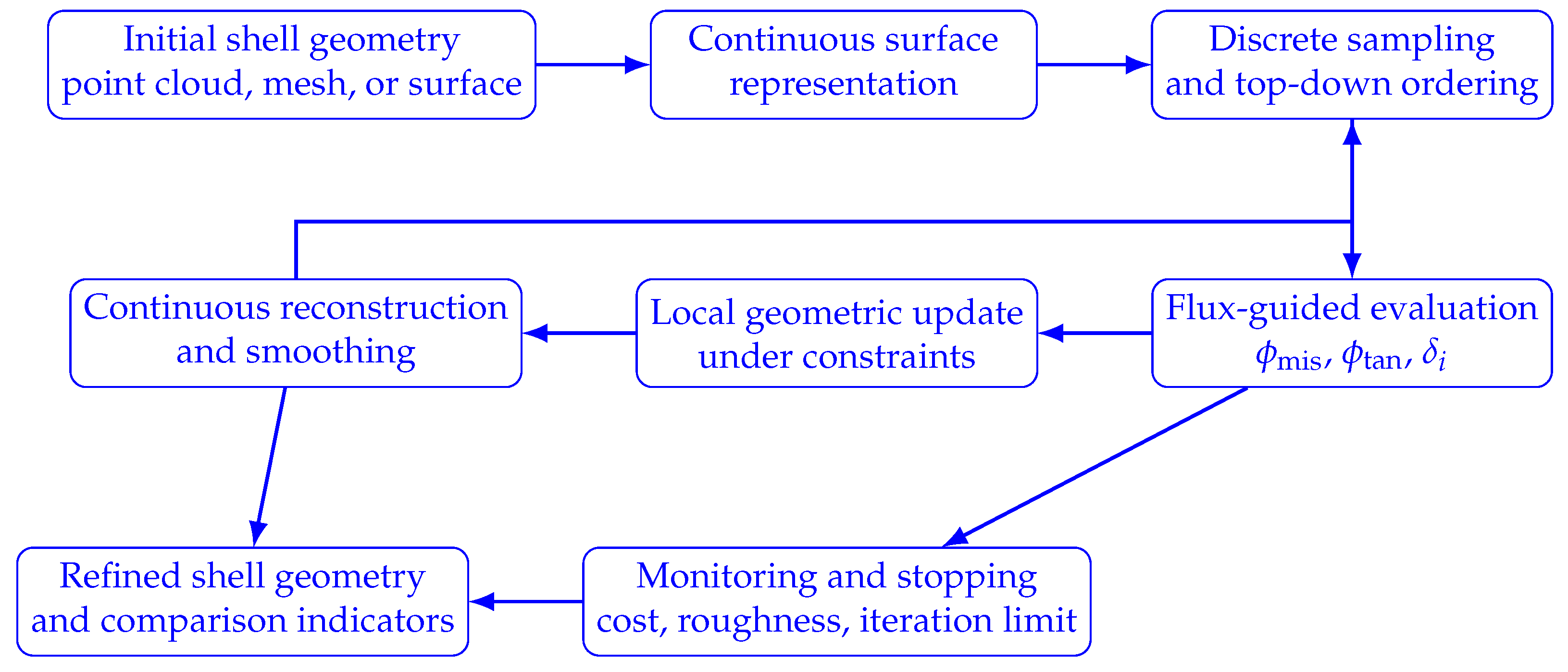
Section 2. The method alternates between a continuous surface representation for stable normal evaluation and geometric control and a discrete sampled representation for local assessment and iterative modification. In the present framework, the refinement is applied in a simplified top-down manner from higher regions toward the supports.
Figure 1 summarizes the complete flux-guided refinement workflow before the detailed step-by-step description.
3.1. Inputs and Notation
The refinement procedure starts from a shell mid-surface
, with a unit normal vector
at each point
and a prescribed transmission field
representing the intended support-directed load-transfer tendency. The normalized field
, the normal-component misalignment measure
, and the tangential-alignment descriptor
have already been defined in Equations (
1) and (
2). In the following method description, these quantities are used as directional compatibility indicators for identifying regions where the prescribed transmission field is less compatible with the current shell surface orientation.
The notation is limited to the quantities directly required by the implemented workflow: the shell surface , the sampled points , the directional indicators and , the local deficiency , and the normalized monitoring function C.
3.2. Step 1: Surface Definition and Continuous Fitting
Starting from an initial architectural or structural shell geometry, a continuous surface model
is constructed. In the general formulation, this surface may be described by a parameterized representation
, where
denotes the corresponding geometric parameters:
The purpose of this step is to ensure a stable normal field and to provide a controllable geometric description for the subsequent discrete updates. In the present demonstration study, however, the workflow is instantiated on analytically defined graph surfaces of the form
, sampled on regular grids. Broader surface-representation options are discussed separately in
Appendix A as possible future extensions rather than as implemented components of the present study.
Requirements: the chosen representation must provide at least continuity, allow local geometric modification, and preserve essential geometric constraints such as supports, fixed edges, plan boundaries, or admissible envelopes.
3.3. Step 2: Discretization and Top-Down Ordering
At iteration k, the current continuous surface is sampled into a point set , together with associated local neighborhoods . To reflect the assumed gravity-driven accumulation in simplified form, the points are processed in a top-down sequence by sorting them with respect to their height coordinate and grouping them into discrete levels , with . This ordering provides a practical level-wise sequence for applying the refinement from higher regions toward the support regions.
Requirements: the sampling density must be sufficient to resolve local geometric changes and to ensure a meaningful definition of neighborhoods and level bands.
3.4. Step 3: Pointwise Flux-Guided Evaluation and Local Deficiency
At each sampled point
, the local unit normal
is computed and the local directional indicators
and
are evaluated from Equations (
1) and (
2). To identify regions requiring geometric correction, a local deficiency measure is introduced by comparing the local directional state at point
i with the corresponding neighborhood average:
Thus,
indicates that the point underperforms relative to its neighborhood in terms of flux-guided directional compatibility, i.e., the local transmission tendency is less favorably aligned with in-surface transfer than in the surrounding region.
This quantity is used only as a local indicator of where geometric correction is needed. It should not be interpreted as a direct stress or force measure, but rather as a geometrically derived directional-compatibility signal.
3.5. Step 4: Local Geometric Update
For points with positive local deficiency, the geometry is updated locally in order to improve the flux-guided directional state. At the discrete level, the generic update may be written as
where
is a step-size parameter,
is a non-negative scaling function, and
is an admissible update direction.
In the present demonstration study, the implemented local updates act on graph surfaces by vertically modifying the sampled geometry, whereas Equation (
5) is written in a more general form to retain the broader geometric interpretation of the workflow. The increase in shell rise observed in the reported cases should therefore be understood as an outcome of the refinement process rather than a prescribed feature of the update formulation itself.
The update rule contains manually selected parameters, including the step-size factor and smoothing-related settings. These parameters are treated as reference values for a controlled proof-of-concept implementation and are not claimed to define a unique or globally optimal update strategy. Their role is to produce stable and interpretable geometric evolution within the selected demonstration cases.
Requirements: the update should avoid excessive geometric noise, prevent self-intersections, preserve boundary and support conditions, and remain numerically stable under the adopted top-down propagation.
3.6. Step 5: Continuous Reconstruction (Envelope Step)
After a level-wise update or a full iteration sweep, the modified discrete geometry is reconstructed into a continuous surface,
This envelope step is essential because stable flux-guided evaluation requires a smooth and well-defined normal field. Without continuous reconstruction, purely discrete local updates would tend to produce oscillatory normals and numerically induced geometric roughness.
Reconstruction may be carried out using the same representation family introduced in Step 3.2, for example, through spline fitting, RBF smoothing, or another constrained surface-rebuilding procedure. In the current implementation, this reconstruction stage is implemented in a simplified form by updating the graph surface’s envelope via smoothing.
The smoothing assumptions used during reconstruction are therefore part of the numerical regularization strategy rather than independent structural parameters. Their influence is examined only through a limited sensitivity assessment in the present paper; a broader robustness study would be required to establish parameter stability more rigorously.
Requirements: the reconstructed surface should preserve the essential geometric constraints and provide at least continuity.
3.7. Step 6: Monitoring, Stopping, and Outputs
The iterative procedure is repeated until a suitable stopping condition is reached. In the present framework, stopping is not defined solely by whether geometric mutation can continue numerically, but by whether the shell has reached a sufficiently refined and still admissible geometry. In practice, stopping may be based on stabilization of the flux-guided directional indicators, reduction of the geometric-update magnitude, acceptable roughness levels, a prescribed maximum number of iterations, or geometrical and architectural constraints. In the present demonstration study, the refinements are terminated after a prescribed iteration number to ensure reproducibility and direct comparison across the selected shell cases. The final geometries should therefore be interpreted as comparable intermediate refined states obtained under the same computational protocol, not as proven stationary optima. A stricter convergence-based implementation would require additional stopping thresholds, for example based on relative changes in , , R, C, and the maximum geometric update magnitude between successive iterations.
For global monitoring and cross-case comparison, a normalized weighted cost function is used:
where
is the mean misalignment measure,
is the associated tangential descriptor of the same directional state,
R is a roughness indicator, and the subscript 0 denotes the corresponding value of the initial shell geometry. This quantity is used as a monitoring and comparison metric rather than as the sole direct driver of the local geometric updates. Although
and
describe the same underlying directional relation from closely related perspectives, both terms were retained deliberately in the present normalized cost function in order to distinguish explicitly between reward and penalty contributions during the sensitivity analysis. Accordingly, the term weighted by
may also be omitted by setting
. Within the present implementation, varying
primarily affects the numerical evaluation of the global score
C, whereas its influence on the final shell geometry remains limited.
The normalized cost function is therefore used as a monitoring and comparison quantity, not as proof of robustness or convergence. The reported sensitivity analysis should be interpreted as a limited parameter-response assessment for representative values of and , rather than as a comprehensive stability study over all weighting, smoothing, and update parameters.
The final output of the workflow is a refined shell surface , along with flux-guided directional maps, geometry-change histories, and global comparison indicators that describe the transition from the initial to the refined geometry.
3.8. Summary of the Workflow
In summary, the proposed method follows the iterative sequence,
applied in a simplified top-down sequence from higher regions toward the supports. The workflow is therefore discrete in its local evaluation and update logic, but continuous in its geometric control and reconstruction. Its purpose is to convert an initially given shell geometry into a geometrically refined version of the same general shell typology, with improved directional compatibility relative to the prescribed transmission field.
4. Surface Representation Used in the Present Implementation
This section focuses on the surface representation used in the implemented numerical examples. Broader mathematical surface representations are discussed separately in
Appendix A as possible extensions beyond the present implementation.
In the present demonstration study, all selected shell cases are implemented as graph surfaces of the form
sampled on regular rectangular grids. This representation provides a transparent and reproducible basis for testing the proposed flux-guided refinement concept, because surface heights, numerical normals, pointwise updates, and smoothing-based envelope reconstruction can be evaluated consistently within the same
MATLAB workflow.
The graph-surface representation also defines the main limitation of the current implementation. It is suitable for the selected height-field shell examples, but it does not naturally represent overhangs, multi-valued surfaces, branching geometries, or genuine topology changes. Therefore, the present implementation should be interpreted as a controlled proof-of-concept for flux-guided refinement of height-field shell geometries, rather than as a general surface-optimization framework for arbitrary shell topology.
The essential requirements for the implemented representation are stable normal evaluation, local editability of sampled points, compatibility with smoothing-based reconstruction, and preservation of the imposed plan domain, support locations, and boundary conditions. Broader candidate representations, including spline/NURBS surfaces, RBF reconstruction, implicit level-set formulations, and topology-related considerations, are discussed only as possible future extensions in
Appendix A, not as part of the implemented workflow.
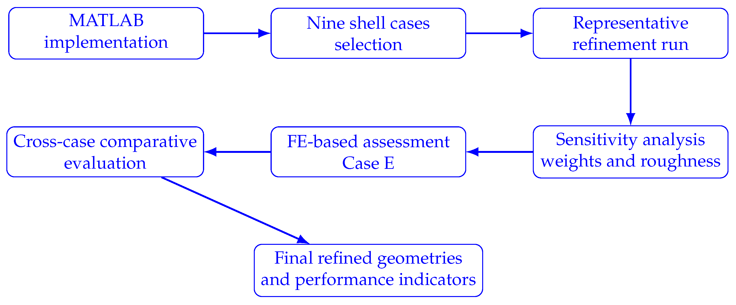
5. Demonstration Cases and Implementation Overview
Figure 2 summarizes the main stages of the demonstration workflow, including implementation, case selection, representative refinement, sensitivity analysis, finite-element assessment, and cross-case comparative evaluation.
5.1. Implementation in MATLAB
The proposed framework was implemented in MATLAB R2019b to maintain control over the computational workflow and examine the method’s behavior in a transparent and reproducible manner. The selected shell cases were defined through case-specific generator functions, executed through a common run script, and processed within the same numerical pipeline. This included geometry generation, surface discretization, construction and evaluation of the prescribed transmission field, computation of local monitoring indicators, top-down updating, envelope reconstruction, and automated figure and data export. All demonstration cases were therefore treated consistently within a unified code structure, allowing the refinement response to be monitored step by step and compared across shell typologies. For computational reproducibility, the corresponding MATLAB scripts, case definitions, input data, and generated outputs will be released in an open LEOPARD repository upon publication.
5.2. Geometric Definition of the Selected Initial Shell Forms
To demonstrate the proposed flux-guided refinement workflow across a broad range of shell morphologies, nine initial shell geometries were selected from the parametric case library implemented in MATLAB. The selected cases were not intended to constitute a statistically exhaustive sample of shell types; rather, they were chosen to cover a deliberately wide range of geometric typologies, support configurations, and initial irregularities, so that the behavior of the proposed refinement procedure could be examined under substantially different starting conditions.
All geometries were generated as parametric graph surfaces of the form
using case-specific mathematical definitions and tunable geometric parameters. In principle, the workflow allows all principal dimensions to be modified, including plan dimensions, support positions, waviness amplitudes, and local geometric perturbations. For the present demonstration study, however, representative dimensions were selected for each case to obtain a varied yet controlled test set. Most cases were generated within a reference plan or bounding box of approximately
, sampled on a regular grid with
. The selected examples therefore differed not only in shape class but also in their actual initial vertical extent, support logic, and overall height-to-span proportions. The corresponding initial geometric quantities, including
and
, are summarized in the comparative tables presented below.
The selected set intentionally included both relatively smooth and geometrically regular forms, such as barrel-vault-, arch-, or ridge-dominated shells, and deliberately more irregular forms, such as shallow rough shells or twisted geometries. This diversity is important because it allows the proposed method to be examined under substantially different geometric starting conditions and enables assessment of whether the refinement procedure yields a consistent directional-indicator response across different shell families.
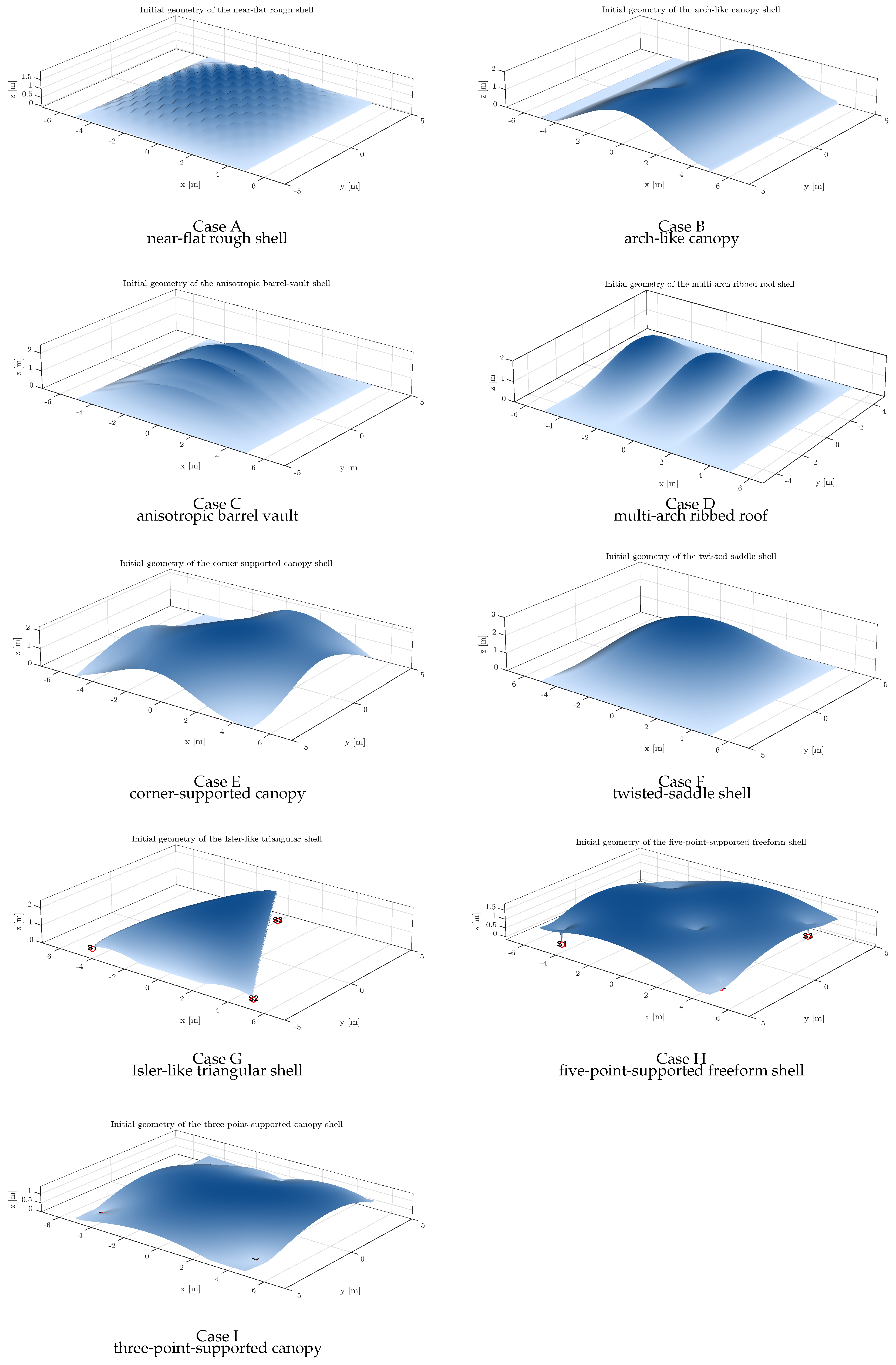
For clarity of presentation, the nine selected shells are labeled here as Cases A–I. The corresponding initial geometries are shown in
Figure 3, and their principal geometric characteristics are summarized below.
Case A: near-flat rough shell. This case represents a very shallow shell with an initial maximum height of approximately over a reference plan. Mathematically, it is defined by a shallow base envelope, high-frequency sinusoidal roughness, and local dent-like depressions. It was included as an intentionally imperfect initial geometry, providing a demanding test of whether the procedure can regularize a weakly curved and noisy shell into a form with improved directional compatibility relative to the prescribed transmission field.
Case B: arch-like canopy shell with inner-support tendency. This surface has an initial maximum height of approximately within an approximately reference bounding box. It is based on a dominant longitudinal arch field combined with transverse fall, free-edge lifting, and an interior depression suggesting an additional support tendency. The underlying mathematical construction combines a main arch-shaped term, edge-lift contributions, and a localized Gaussian-type inner dip. The case was selected because it introduces non-uniform support logic and a partially free-edge canopy morphology.
Case C: anisotropic barrel-vault shell. This geometry has an initial maximum height of approximately over a plan. It is generated from a barrel-vault-type main curvature combined with anisotropic transverse waviness. In mathematical terms, a cosine-like vault in one principal direction is modulated by multiple ripple functions in the orthogonal direction. The case represents a shell with a clear dominant geometric direction but with deliberately introduced transverse irregularities.
Case D: multi-arch ribbed roof shell. This case has an initial maximum height of approximately over a reference plan. It is defined through repeated arch-like ridges distributed across the plan, resulting in a ribbed roof morphology. The mathematical form is based on repeated cosine-type ridges combined with a tapering term. It was selected to examine how the proposed workflow behaves for shells whose geometry is segmented into multiple ridge-dominated regions.
Case E: corner-supported canopy shell. This case has an initial maximum height of approximately within a bounding box. The shell is supported only near the four corners, while the intermediate edges remain free and lifted. The surface is defined by combining arch-like interior uplift, saddle-type curvature, skewness, and mild wave-like irregularities, multiplied by a corner-support factor that suppresses the surface at the support points. This case introduces a support configuration different from line-supported shells and is therefore useful for examining support-sensitive refinement behavior.
Case F: twisted-saddle shell. This shell has an initial maximum height of approximately over a plan. It is obtained from a dome-like base function modified by a twist term and a saddle-type distortion. In mathematical terms, the surface combines a smooth cosine envelope with mixed -type twisting and -type anticlastic perturbations. The case was chosen because it provided a controlled example of a globally smooth but geometrically distorted shell.
Case G: Isler-like triangular shell. This case has an initial maximum height of approximately . Unlike the other cases, its active domain is triangular rather than fully rectangular, although it is embedded in a comparable bounding box for numerical convenience. The geometry is defined using barycentric-coordinate-based shape functions over a triangular planar domain, including a base-dome-like term, a crest-oriented ridge term, and a sagging contribution near one edge. It was selected to include a shell typology with a different plan geometry and a three-point-supported structural logic.
Case H: five-point-supported freeform shell. This case has an initial maximum height of approximately within a bounding box. It is a freeform canopy supported at five discrete points, namely four peripheral supports and one off-center interior support. The mathematical construction uses a support-distance blending field, a broad freeform crown, and additional wave-like irregularity. It was selected to examine the method on a shell whose geometry is primarily governed by multiple-point supports rather than edge supports.
Case I: three-point-supported canopy shell. This surface has an initial maximum height of approximately within a bounding box. It is a three-point-supported canopy generated by blending the distances to three discrete support locations and combining them with a broad canopy crown and mild asymmetry. Compared with Case G, which uses a triangular active domain, Case I remains a canopy-like graph surface over a rectangular plan. It was selected to represent a point-supported shell with a comparatively simple mathematical definition.
Together, the selected cases cover a wide spectrum of initial shell conditions, including shallow rough shells, ribbed roofs, barrel-vault-like forms, twisted anticlastic surfaces, corner-supported and point-supported canopies, and a triangular Isler-inspired shell. This diversity was intentional: the aim was not to optimize a single preferred shell family, but to show that the proposed discrete–continuous flux-guided workflow could be applied consistently to initial geometries with different mathematical definitions and initial height ranges.
5.3. Representative Refinement Run
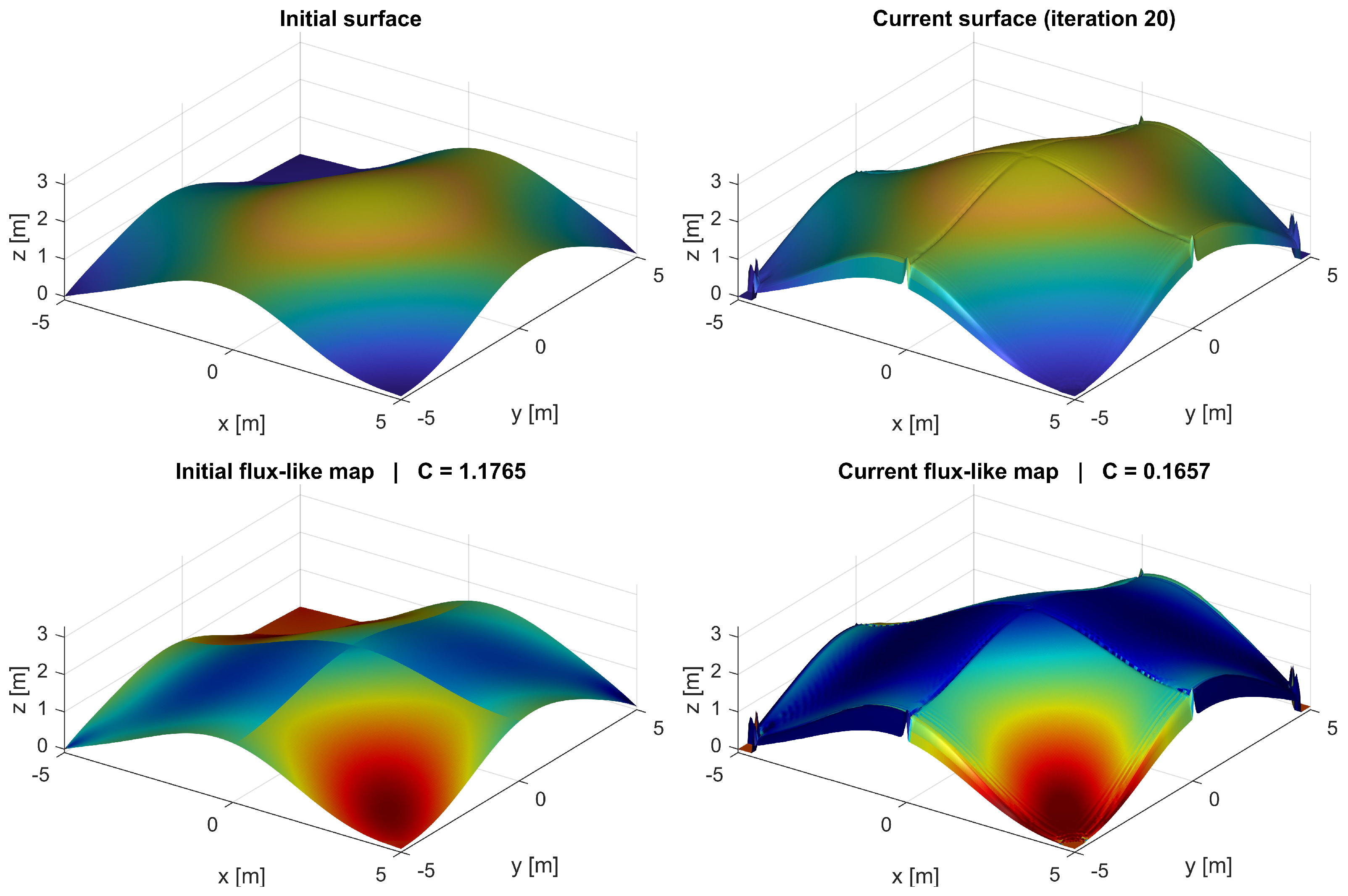
Figure 4 presents a representative refinement run for Case E, the corner-supported canopy shell. This case was selected because it combines a free-edge canopy morphology with a support-sensitive configuration in which gravity-related transfer is directed mainly toward four localized corner supports.
Starting from the initial surface, the shell was discretized in MATLAB, a support-directed transmission field was evaluated at the sampled nodes, and local geometric corrections were progressively applied in a simplified top-down manner. Regions showing weaker local tangential tendency or stronger directional incompatibility relative to their neighborhood were updated and then reconstructed into a smooth continuous envelope for the next iteration.
The figure illustrates the cumulative effect of this discrete–continuous loop. The shell evolved through repeated local corrections rather than through a single global transformation, while the lower-row maps show the accompanying redistribution of flux-guided directional incompatibility. The incompatibility maps provide a spatial comparison of the initial and refined directional states, while the normalized monitoring value C summarizes the global refinement trend.
5.3.1. Normalized Weighted Monitoring Function
The normalized monitoring quantity
C, defined in Equation (
7), was used to compare the refinement response across iterations and selected parameter settings. Here,
,
, and
are user-defined weighting factors,
is a small regularizing constant,
and
denote the current mean misalignment and tangential-alignment measures, and
R is the current roughness indicator. The subscript 0 denotes the corresponding initial value used for normalization. Lower values of
C indicate an improved balance between reduced directional misalignment, increased tangential alignment, and controlled geometric smoothness within the adopted monitoring formulation.
5.3.2. Practical Role in the Iterative Procedure
The quantity
C is used for monitoring and comparison rather than for directly driving the local geometric updates. The geometry evolves through the flux-guided local correction rule, whereas Equation (
7) provides a compact global indicator for comparing iterations and shell cases on a common basis. This distinction is important because the raw quantities
,
, and
R may differ in scale across shell families. Although
and
describe the same underlying directional relation from closely related perspectives, both terms were retained here only to distinguish between penalty and reward contributions in the sensitivity analysis. The iteration histories are therefore used to compare the evolution of the monitored quantities under a fixed computational setting, not to demonstrate convergence to a stationary optimum. If the indicators continue to change at the final iteration, the reported geometry should be understood as the refined state reached after the prescribed iteration budget. This interpretation was adopted consistently for all selected cases to maintain reproducibility and comparability.
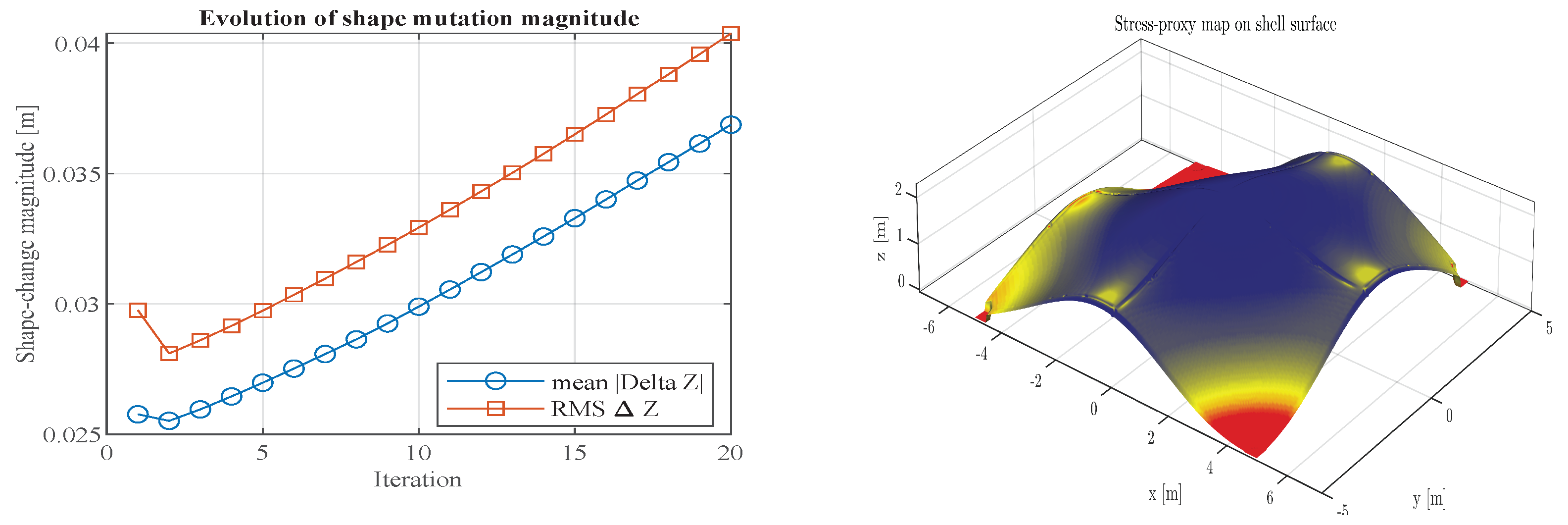
Figure 5 complements the representative refinement run by showing the shape-mutation history and the qualitative geometric-demand proxy for Case E. The geometric-demand proxy is used only for qualitative visualization and is not interpreted as a substitute for rigorous stress analysis or as independent evidence of structural improvement. The optimized geometry shows a redistributed proxy pattern that is consistent with the directional-indicator trend, but the structural interpretation is based only on the representative FE comparison discussed later.
5.4. Interpretation of the Final Refinement Response for Case A
For Case A, the final refinement run indicates a clear geometric shift, accompanied by a corresponding change in the directional indicators relative to the initial configuration. The refined shell became visibly higher overall, as reflected by the increase in from approximately to and in from approximately to . In other words, the initially shallow and relatively flat shell evolved toward a form with a more pronounced shell-like rise. Within the present interpretation, such a change is consistent with a gradual shift toward a geometry that is more directionally compatible with the assumed membrane-type gravity-load transfer tendency.
At the same time, the two principal directional indicators improved. The value of increased from approximately to , indicating that the prescribed transmission field developed, on average, a stronger tangential component relative to the shell surface. In parallel, decreased from approximately to , showing that the normal component of the transmission field relative to the shell surface was reduced. Taken together, these changes suggest that the increase in rise was accompanied by improved directional compatibility between the shell geometry and the prescribed transmission field.
This improvement, however, was accompanied by a pronounced increase in geometric roughness. The roughness measure increased from approximately to , showing that the refined shell became locally less smooth and more irregular than the initial one. Thus, the refinement procedure did not achieve its directional improvement without cost; rather, it did so at the expense of geometric smoothness. This trade-off is characteristic of the current implementation: the local update strategy can improve the directional indicators, but it can also introduce numerically induced local surface oscillations.
Nevertheless, because the reduction in misalignment and the increase in tangential alignment were sufficiently strong, the overall normalized weighted cost C decreased from approximately to . Case A therefore illustrates that the proposed procedure can improve the adopted directional-compatibility indicators for an initially shallow and irregular shell, although this improvement is accompanied by increased local roughness.
In the shown cases, the roughness penalty reduced local oscillations and produces smoother refined surfaces while preserving the general directional-refinement trend. The comparison indicates that roughness regularization mainly affects local surface quality, while the overall direction of geometric refinement remains consistent.
5.4.1. Sensitivity of the Refinement Response to the Weights
Since all terms in the monitoring function are normalized by their respective initial values, the weights primarily serve as relative importance factors rather than absolute scaling parameters. In the present study, was therefore kept fixed as the reference coefficient, and the sensitivity assessment was restricted to the two remaining parameters, namely and . Accordingly, only weights.wTan and weights.lambdaR were varied. The present sensitivity study should be interpreted as a limited parameter-response assessment rather than as a full robustness or convergence proof. The reference values of the weights and smoothing parameters were selected manually to obtain stable and visually interpretable refinement behavior across the demonstration cases. The purpose of the sensitivity analysis is therefore to examine whether the main qualitative trends, especially reduction of directional misalignment, increase of tangential alignment, and suppression of excessive roughness, remain consistent under representative changes of and . It does not establish uniqueness of the obtained geometry, global optimality, or parameter-independent convergence.
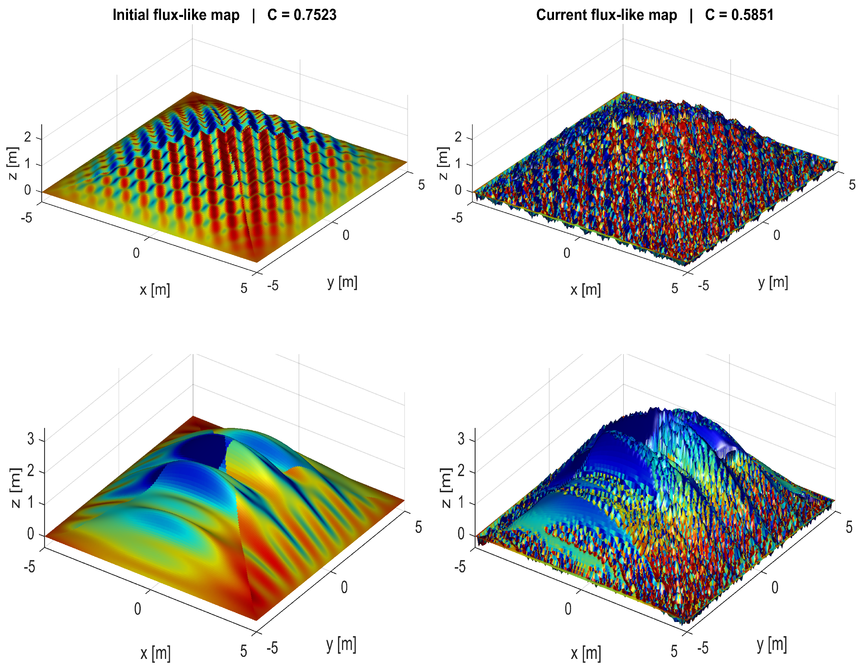
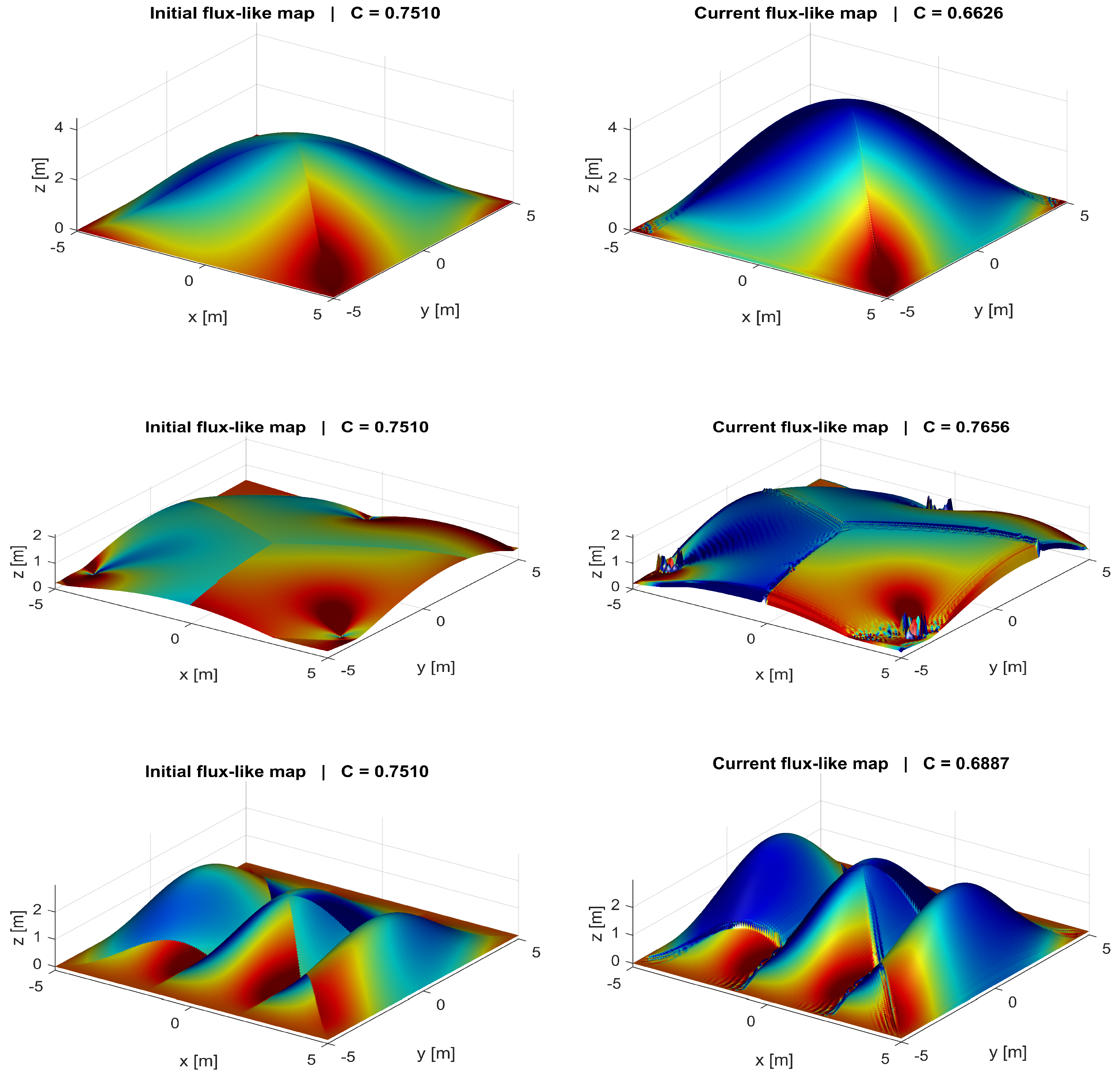
Figure 6 shows the influence of the roughness-penalty term on the refinement response for Cases A and C. Without roughness control
, the refinement procedure can improve the directional indicators but may produce strong local oscillations. With roughness regularization
, the refined surfaces remain visibly smoother while preserving the general tendency toward forms with improved directional compatibility with the assumed membrane-type transfer tendency.
Although appears numerically small, its effect is pronounced because the roughness measure can increase substantially during the iterative process. The figure therefore indicates that roughness control is important for obtaining geometrically interpretable results. The results indicate that the roughness penalty is one of the most influential parameters in the current implementation. When , the local update procedure can still improve the directional indicators, but the resulting geometry may develop strong local oscillations. Introducing a small roughness penalty reduces these oscillations and produces smoother surfaces, although it does not guarantee convergence to a unique optimum. The role of is more limited in the present implementation, because and describe the same directional relationship from complementary perspectives. Therefore, changes in mainly affect the monitored value of the normalized cost function, while the geometric evolution remains governed primarily by the local deficiency rule and the roughness control.
The selected reference parameters provide visually interpretable refined geometries for the shown cases. This interpretation is discussed in the text rather than in the figure caption.
From a conceptual point of view, increasing does not introduce a new geometric mechanism; it only changes the relative balance between penalty and reward in the normalized monitoring function. The numerical results show that varying mainly affects the value of the global score C, while its influence on the final shell geometry remains limited. The geometric evolution is governed primarily by the local directional correction rule rather than by the weighted global metric.
In the subsequent analyses,
and
were adopted as the reference weighting parameters, since this combination provided a practical balance between geometric regularity and directional adaptation according to the adopted indicators. Representative refined forms obtained with these reference parameters are shown in
Figure 7 for Cases F, I, and D.
Interpretive Role of the Reward Term
Because and describe the same directional relation from closely related perspectives, the reward term is not strictly required for mathematical completeness. It was retained here to distinguish explicitly between penalty and reward contributions in the sensitivity analysis. The results indicate that this term mainly affects the numerical value of C and has only a limited influence on the final shell geometry.
5.4.2. Evolution of Shape-Mutation Magnitude and Stopping Criteria
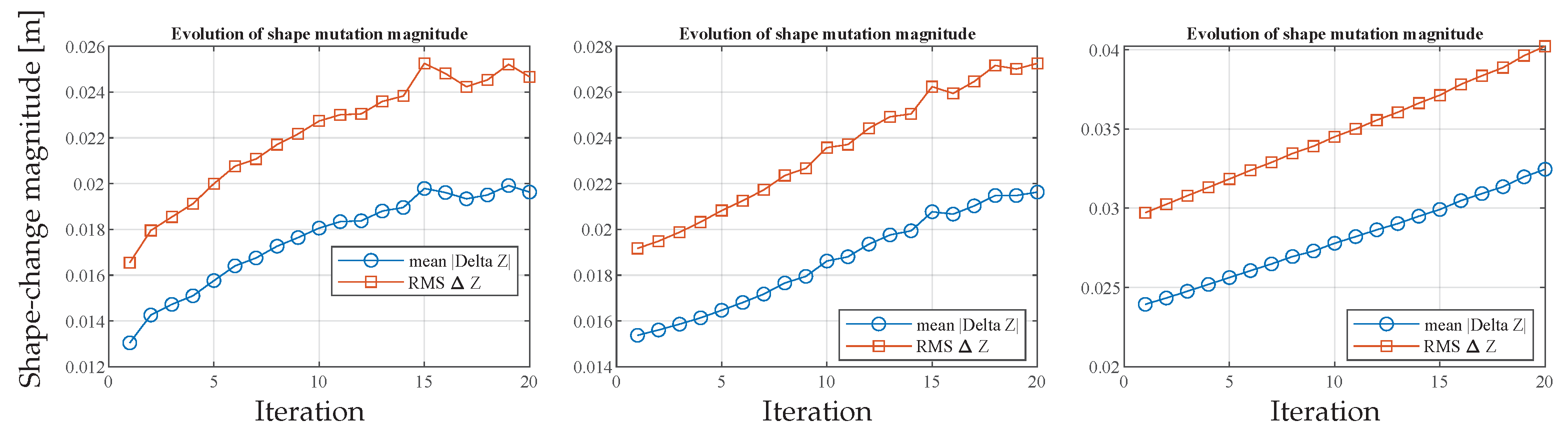
Figure 8 illustrates the evolution of the shape-mutation magnitude for three representative cases. The iteration histories report both the mean absolute height change and the RMS height change, allowing the magnitude and spatial non-uniformity of the refinement process to be compared. In all examples, both
and
increase gradually with iteration number, indicating that the refinement procedure remains geometrically active over the prescribed iteration budget. The larger
values further show that the mutation is spatially non-uniform and influenced by localized regions of stronger geometric adaptation.
This observation suggests that additional iterations could still produce further geometric change. Nevertheless, the stopping condition of the procedure should not be based on numerical evolution alone, but also on geometric admissibility, smoothness, and preservation of the intended shell typology. Excessive geometric amplification may move the structure away from the intended form or introduce undesirable local roughness. The aim of the present framework is therefore not to replace the original form by a fundamentally different one, but to convert a given configuration into a geometrically refined version of the same general shell typology with improved directional compatibility. Accordingly, the refinement procedure should be terminated once the geometry has become sufficiently improved according to the adopted indicators while remaining consistent with the intended shell form, even if further iterations would continue to generate additional numerical mutation.
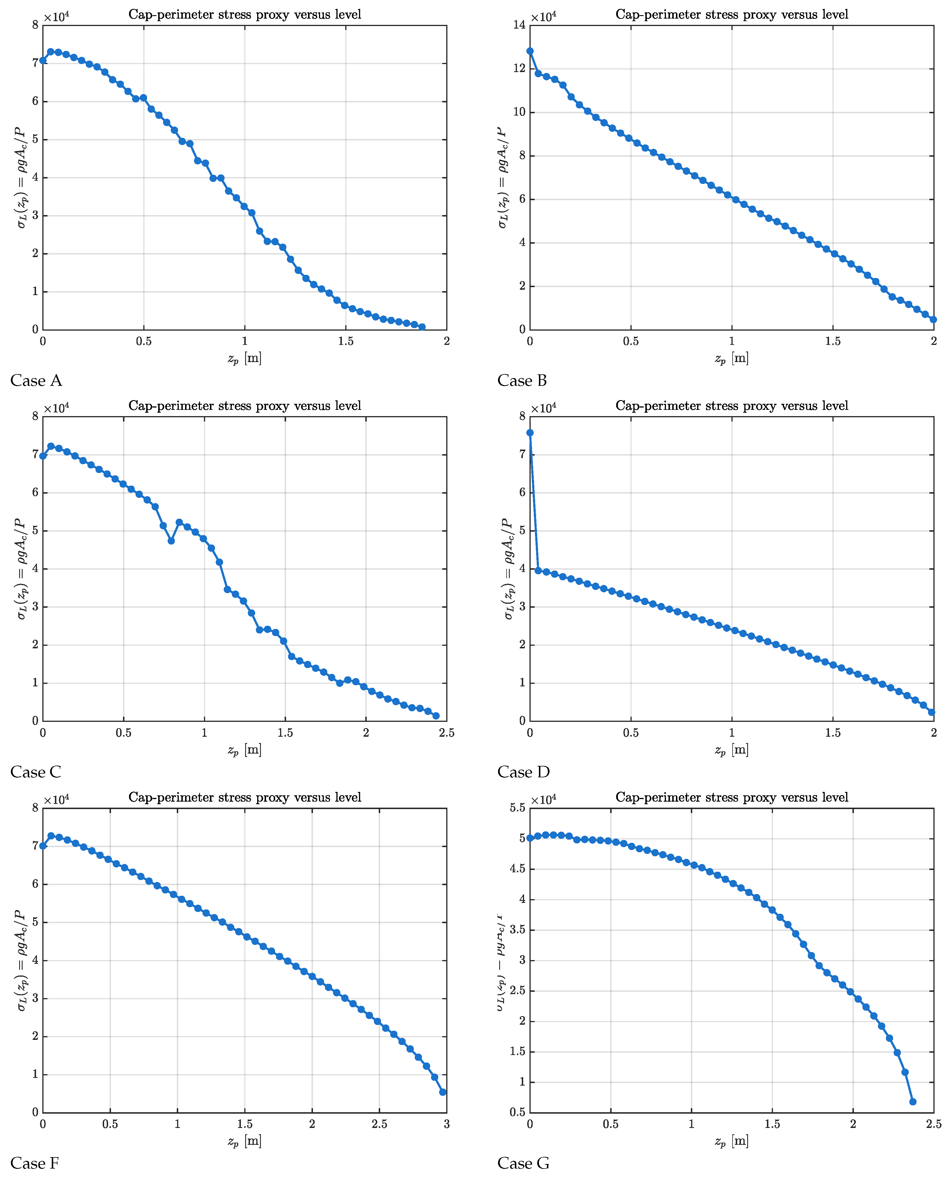
5.4.3. Initial Level-Based Geometric-Demand Proxy Distributions
Figure 9 compares the level-based qualitative geometric-demand proxy for the selected initial shell geometries. The quantity
is used only as a qualitative geometric-demand proxy and is not intended as a substitute for rigorous stress evaluation. It provides a visual indication of how the simplified accumulated gravity-related demand varies over the shell height as a function of geometry. In general, the curves decrease with increasing
, which is consistent with the fact that lower shell levels are associated with a larger tributary shell area, whereas near the crown only a limited cap area remains above the considered level.
At the same time, the individual cases exhibit distinct curve shapes, indicating that the initial geometry influences the distribution of this simplified geometric-demand proxy. Some cases display a comparatively smooth and nearly monotonic decrease, whereas others show stronger curvature changes or localized irregularities. These differences reflect variations in shell rise, plan geometry, support configuration, and local surface morphology. In this sense, the figure provides a qualitative baseline for comparing how different initial shell forms distribute the adopted gravity-related proxy over height.
From the perspective of the present study, this observation is used only for geometric interpretation. It supports the idea that changes in shell geometry can alter the adopted proxy distribution, but it does not by itself demonstrate structural improvement or membrane-dominated behavior. The proxy-based comparison therefore serves as a qualitative baseline for later interpretation of the refined geometries, while structural assessment remains limited to the representative finite-element comparison discussed separately.
5.5. Surface Reconstruction and FE-Based Assessment of the Representative Case
To examine whether the geometric tendency produced by the proposed flux-guided refinement procedure is also reflected in a conventional structural-analysis environment, a representative FE-based assessment was carried out for Case E. The initial and refined shell geometries were exported from MATLAB as point coordinates , transferred to Rhino3D, and reconstructed as lofted surfaces. This rebuilding step filters part of the local pointwise irregularity and reduces some of the visible numerical noise. The adopted surface-fitting strategy may therefore influence geometric regularity and, to some extent, the detailed FE response.
The reconstructed geometries were then transferred to Abaqus 2024 for finite-element evaluation. A uniform shell thickness of and a linear-elastic material model were adopted, and the shells were subjected only to gravity loading. For the representative comparison, two geometries of Case E were considered, namely the initial shell at iteration 0 and the refined shell after 20 iterations.
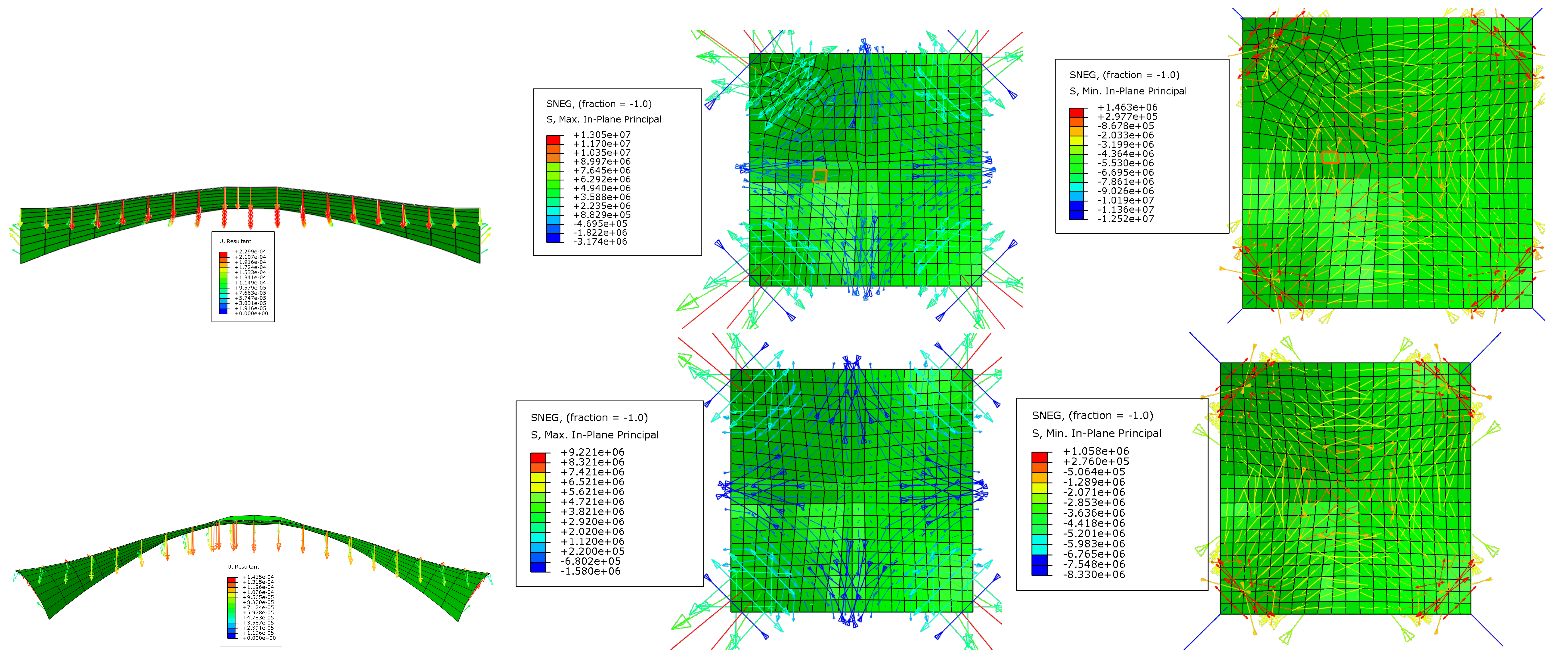
Within the scope of the present study, the FE investigation was treated as a representative structural consistency check rather than as a full validation of the proposed method. Its purpose was to examine whether the geometric tendency predicted by the flux-guided indicators was reflected in conventional shell-analysis quantities for one representative case. The FE results were therefore not used to prove general structural optimality, but to provide an additional quantitative comparison between the initial and refined geometries of Case E under the same modeling assumptions. As the primary comparison quantity, the principal stress distribution was examined. As shown in
Figure 10, the refined geometry exhibits a redistribution of stresses relative to the initial shell. Over large parts of the shell surface, the principal stress level is reduced, and the maximum displayed principal stress decreases from approximately
in the initial shell to approximately
in the refined shell, corresponding to a reduction of about
. This quantitative reduction is consistent with the direction of improvement indicated by the flux-guided geometric indicators, although it does not by itself constitute a general validation of the method for all shell types or loading conditions.
The FE model was defined consistently for the initial and refined geometries in order to maintain comparability. Both reconstructed surfaces were modeled in Abaqus 2024 using four-node shell elements. The same shell thickness, linear-elastic material model, gravity loading, support idealization, and meshing procedure were used for both geometries. The meshes were generated with comparable element sizes over the two reconstructed surfaces so that the initial and refined models could be compared under equivalent discretization assumptions. The four corner support regions were restrained to represent the support configuration used in the geometric model, while the remaining shell surface was left free. Gravity was applied as the only load case. The analysis was performed using a linear static general step with the default Abaqus/Standard solver settings. The FE comparison was therefore limited to a linear-elastic gravity-load assessment of one representative shell case. It was not intended to represent nonlinear response, instability behavior, imperfection sensitivity, construction-stage effects, or realistic design load combinations.
At the same time,
Figure 10 also shows that local stress concentration remains pronounced near the four corner support regions. This should not be interpreted as contradicting the overall refinement trend indicated by the refined geometry. As the load-transfer tendency becomes more directed toward the supports, local support-region demand may remain pronounced or even become more concentrated. Such behavior would require local detailing, possible thickening, or reinforcement design in practical structural applications. Accordingly, local stress concentration near the supports is not eliminated by the present geometric refinement and remains a limitation to be addressed in subsequent structural design.
For practical structural applications, this step should be followed by standard structural analysis and design procedures to determine the required shell thickness, structural dimensions, and possible reinforcement or detailing measures. In addition, after this FE-based assessment stage, architectural, geometric, and constructability-related constraints may be incorporated more explicitly in order to judge the admissibility of the evolving form and to define suitable stopping criteria for the iterative refinement process.
Figure 11 extends the FE-based assessment shown in
Figure 10 by complementing the principal-stress comparison with the corresponding deformed shapes and the SNEG maximum and minimum in-plane principal stresses for the initial and refined geometries of Case E. The refined shell shows a modified in-plane stress pattern and a smaller deformation under gravity loading within the adopted linear-elastic FE model. This comparison provides case-specific supporting evidence that the refined geometry produces a response trend consistent with the proposed directional indicators. It is not interpreted as proof of general structural improvement, structural optimality, or fully membrane-dominated behavior.
The comparison in
Table 1 strengthens the structural interpretation by adding quantitative FE-based indicators to the previously qualitative assessment. Nevertheless, the validation remains intentionally limited. It is restricted to one representative shell case, gravity loading, a linear-elastic material model, and the adopted FE discretization and boundary conditions. The proposed flux-guided indicators should therefore be interpreted as geometric compatibility measures whose trends can be checked against FE response quantities, rather than as direct substitutes for membrane–bending decomposition, strain-energy evaluation, buckling assessment, or code-based structural verification. A broader validation against such established shell-performance metrics is identified as an important extension of the present framework.
For this reason, the FE-based comparison is not interpreted as a demonstration of fully membrane-dominated behavior. A rigorous verification of membrane action would require, at minimum, decomposition of membrane and bending stress resultants, comparison of membrane and bending strain-energy contributions, and assessment of stability-related quantities. Such measures were not included in the current implementation. The present FE comparison is therefore used only to check whether the refined geometry produces a response trend that is consistent with the proposed geometric indicators under the adopted linear-elastic gravity-load model.
Accordingly, the proxy-based plots are not used as validation metrics. The structural interpretation is based only on the representative FE comparison, and even that comparison is presented as case-specific supporting evidence under the adopted modeling assumptions. The proxy measures are retained only as qualitative visualization tools for the assumed gravity-related demand distribution.
The limitations of the FE-based assessment are also explicitly acknowledged. Only one representative shell case, Case E, was examined in the present Abaqus-based comparison, and the analysis was restricted to gravity loading with a linear-elastic material model. The results therefore cannot be generalized to nonlinear shell response, instability behavior, imperfection sensitivity, support-settlement effects, construction-stage effects, or realistic design load combinations. The FE comparison is included only to provide a first case-specific consistency check between the geometric refinement trend and a conventional finite-element response. A broader validation campaign would be required before drawing general conclusions about structural performance.
Overall, the reported FE results should be read as a limited representative assessment based on the adopted boundary conditions, shell modeling assumptions, mesh discretization, gravity loading, and linear static solver setting. They are not used to justify broad claims such as general structural improvement, membrane-dominated behavior, or optimal shell performance.
5.6. Comparative Evaluation Across the Selected Shell Cases
5.7. Relative Changes in the Principal Monitoring Indicators
Table 3 provides a comparative view of the relative changes in the principal monitoring indicators and is therefore useful for assessing the consistency of the refinement response across the selected shell families. The values of
are positive in all cases, indicating that the tangential-alignment descriptor associated with the prescribed transmission field increased throughout the considered set of examples. The magnitude of this increase ranged from approximately
to
, suggesting that the procedure produces a consistent directional-indicator response across different shell typologies and support conditions.
A similarly important pattern was observed in the values of . In all cases, these values were negative, meaning that the normal-component misalignment of the transmission field decreased after refinement. The reduction lay roughly between and , which is notable within the adopted geometric-indicator framework. This trend is consistent with the central interpretation of the study: as the prescribed transmission field develops a weaker normal component and a stronger in-surface tendency, the geometry becomes more directionally compatible with the assumed membrane-type gravity-load transfer tendency. This interpretation remains indicator-based and should not be read as proof of a fully membrane-dominated stress state.
The values of provide a more balanced picture because they reflect the competition between two opposing effects: flux-guided directional improvement on the one hand and increasing geometric roughness on the other. In all cases, C decreased, indicating that the net outcome of the refinement procedure remains favorable within the adopted monitoring function. In some cases, however, such as Cases B and D, this decrease was only marginal. This should not be interpreted as a failure of the directional-refinement concept; rather, it indicates that the increase in roughness partly offsets the directional gains within the aggregated monitoring function. The more appropriate interpretation is therefore that the present implementation improves the adopted directional indicators, but does not yet suppress local geometric noise sufficiently.
The main conclusion drawn from
Table 3 is therefore that the current limitation of the method appears to be primarily related to geometric regularity rather than to the directional-refinement logic itself. The results suggest that the procedure can steer the shell geometry toward a more tangential directional state relative to the prescribed transmission field, although part of this improvement is masked in the global cost function by the accompanying increase in surface roughness. Because this roughness is local and numerical in character, it may, in principle, be reduced through a subsequent surface-fitting, envelope-reconstruction, or controlled-smoothing stage without necessarily eliminating the broader geometric shift. In this sense, the table supports the view that the proposed refinement strategy is promising as a conceptual geometric pre-optimization tool, while also indicating that a final geometric regularization step is still required before practical structural use.
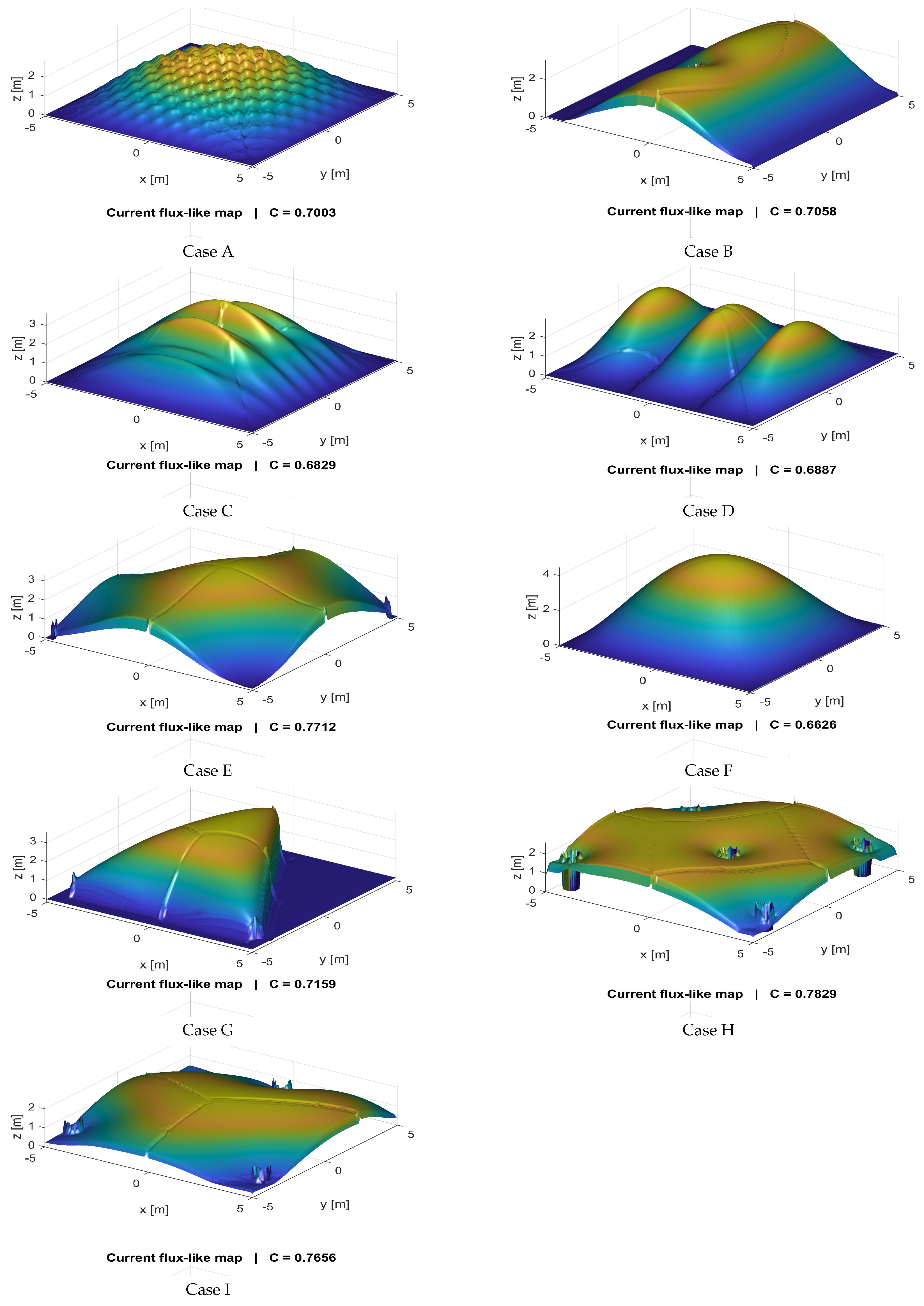
The cross-case interpretation is provided in the main text. Despite differences in the initial geometries, the refined forms show a consistent trend toward increased rise and improved directional compatibility with the prescribed transmission field. This trend is interpreted as a geometric indicator response, not as proof of general structural optimality.
Figure 12 provides a compact visual overview of the final refined geometries for all the selected cases and indicates that the proposed framework yields a consistent qualitative refinement tendency across substantially different shell families. These trends should be interpreted as improvements in the adopted geometric and directional indicators, not as proof of general structural performance or optimality. A rigorous confirmation would require additional shell-specific metrics, including membrane–bending decomposition, strain-energy partitioning, stability assessment, and broader load-case evaluation.
5.8. Limitations of the Present Framework
The present framework has several limitations. First, the study is restricted to gravity-dominated loading and a support-directed transmission field defined for this condition. The results should therefore be interpreted as evidence of the feasibility of the proposed flux-guided refinement concept under self-weight, rather than as a complete refinement procedure for arbitrary load combinations. Second, the current implementation is primarily geometric and indicator-based. The adopted directional measures are mechanically motivated, but they do not replace full structural verification; the transmission field used during refinement is a structural guidance field rather than an exact internal-force solution. Third, the method remains sensitive to local numerical roughness. Even with roughness regularization, local oscillations may still develop during the iterative process, so the directly refined geometry should not yet be regarded as a final production shape. Finally, the stopping criterion is not yet fully structural. More advanced criteria linked to convergence, geometric admissibility, and FE-based response measures could strengthen the framework in future work.
6. Conclusions
This study presented a discrete–continuous flux-guided shape-refinement framework for the early-stage mechanics-informed refinement of freeform shell geometries under gravity loading. The method was developed as a lightweight intermediate step between intuitive geometric design and later high-fidelity structural verification. It is not intended to replace equilibrium-based form-finding, detailed finite-element optimization, or code-based structural design; instead, it provides an interpretable geometric procedure for steering an initially defined shell toward a form that is more directionally compatible with a prescribed support-directed transmission field.
The main findings of the study can be summarized as follows:
The proposed workflow combines a prescribed transmission field, local flux-guided directional indicators, top-down geometric updates, and continuous surface reconstruction within a single iterative refinement procedure.
Across the nine investigated shell cases, the refinement consistently reduced normal-component misalignment and increased tangential alignment relative to the prescribed transmission field.
The refined forms showed a general tendency toward increased shell rise and more shell-like directional characteristics; however, this trend should be interpreted as a result of the adopted guidance field and update strategy, not as proof of globally optimal shell behavior.
The representative finite-element comparison for Case E provided case-specific supporting evidence that the refined geometry reduced deformation and principal stress levels over large surface regions within the adopted linear-elastic gravity-load model.
The study also showed that geometric roughness remains a critical limitation of the current implementation. Explicit roughness regularization, improved smoothing, and more robust stopping criteria are therefore necessary before the method can be used for final structural design.
Overall, the results support the feasibility of the proposed flux-guided refinement concept as a conceptual geometric pre-optimization tool for freeform shells under self-weight. The observed improvements should be understood as improvements in directional compatibility and as case-specific FE response trends, rather than as general proof of improved structural performance.
Future work should extend the framework by incorporating membrane–bending stress-resultant decomposition, membrane and bending strain-energy comparisons, convergence-based stopping criteria, nonlinear FE analysis, instability and imperfection-sensitivity studies, support-condition variations, construction-stage effects, and realistic load combinations. These extensions are necessary before the proposed geometric compatibility indicators can be related more rigorously to established shell-efficiency and structural-performance measures. A more systematic parameter study, including wider ranges of , , smoothing parameters, update step size, and iteration number, is also required to establish robustness, parameter stability, and convergence behavior.