Abstract
Maritime shipping companies have identified continuous tracking of intermodal containers as a key tool for increasing shipment reliability and generating important economies of scale. Equipping all dry containers with an Internet-connected tracking device is a need in the global shipping market that is still waiting to be met. This paper presents the methods and tools to build and test a prototype of a Container Tracking Device (CTD) that integrates NB-IoT, BLE Mesh telecommunication and low-power consumption technologies for the massive deployment of the IoT. The work was carried out as part of a project to build the so-called “5G Global Tracking System”, enabling several different logistic applications relying on massive IoT, M2M standard platforms, as well as satellite networks to collect data from dry containers when the vessel is in open sea. Starting from a preliminary phase, in which state-of-the-art technologies, research approaches, industrial initiatives and developing standards were investigated, a prototype version of the CTD has been designed, verified and developed as the first fundamental step for subsequent industrial engineering. The results of specific tests are shown: after verifying that the firmware is capable of handling the various functions of the device, a special focus is devoted to the power consumption measurements of the CTD to size the battery pack.
1. Introduction
The standardization of logistics has made faster and more efficient connectivity between different parts of the world possible, facilitating international trade significantly and contributing to the spread of globalization. Ninety percent of the freight is shipped by sea travel in dry containers. Although goods loaded in dry containers generally do not require specific environmental controls, damage to contents, delivery delays, theft or loss during shipments are not uncommon. Cargo ships can transport up to several thousand containers, and thanks to their increasing sophistication and digitization, they are becoming increasingly efficient. The demand for marine cargo services is ever-increasing in the supply chain, and therefore, it is crucial to know the status of not only the freight as a whole but of each individual container. Moreover, for some new types of merchandise, such as Electric Vehicles (EVs), there is a growing interest in the possibility of transporting them via containers on container ships. The current regulations of maritime transportation safety do not currently detail any additional equipment or specific vessel requirements to address the shipment of EVs in containers. Despite that, EVs are considered dangerous goods with a specific IMDG (International Maritime Dangerous Goods) code and may be stowed with other IMDG cargoes; therefore, shipping companies are encouraged to assess their own protocols and procedures and proactively implement appropriate additional safety measures, intended to best enhance their own vessels’ safety and to protect their crew, their vessel, the cargo and the marine environment.
Thus, for EVs and many other kinds of freight, it is very beneficial to know that the intensity of mechanical shocks, temperature, humidity and pressure of the container are within a certain threshold. For these reasons, shipping companies primarily, as well as other actors in the logistics chain (freight forwarders, port and customs authorities, shipment clients) are showing a strong interest in equipping all dry containers with a real-time monitoring and tracking device.
The tracking devices should be able to transmit data from each container in real-time and thereby make supply chains more transparent and efficient. For example, they can supply location data based on GPS, measure ambient temperature and monitor any sudden shocks. The devices should integrate the latest energy-harvesting technology and low-power consumption techniques to ensure that they have ultra-long service lives with high-rate data transmission.
The digitalization of maritime transportation for dry containers is a complex challenge that requires the development of a global operational monitoring system at every stage of the containers’ intercontinental journeys (on land and at sea).
The challenge has been taken up by the project “5G Smart Edge Node and Smart Objects Enabling Reliable Services Extended All over the Seas” (5G SENSOR@SEA), funded by the Artes 4.0 program of the European Space Agency [1]. The project realized the so-called “5G Global Tracking System (5GT System)”, enabling several different logistic applications relying on massive IoT, OneM2M compliant [2] platforms, as well as satellite networks, to collect data from dry containers when the vessel is in open sea [3].
The 5GT System comprises an NB-IoT framework on top of a hybrid terrestrial–satellite network, providing information coming from the cargo-ship scenario (maritime domain) and port terminals (terrestrial domain) to a oneM2M IoT cloud platform, making it available to the customers’ application (see Figure 1).
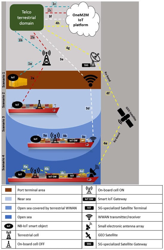
Figure 1.
A 5GT system data flow based on different scenarios.
A fundamental component of the 5GT System is the monitoring and tracking device placed on dry containers, the so-called Container Tracking Device (CTD). It was designed and developed by CNIT researchers, starting from the creation of a prototype and culminating in the engineered device used in final tests conducted in intercontinental navigation.
The research work presented in the present paper is part of the 5GT System project [1]. The paper addresses the challenge of designing, developing and testing the first prototype version of the CTD. The goal is to show the initial fundamental step that enabled the subsequent marine-grade implementation of the devices used in the final assessment of the 5GT System in an operational environment, which will be presented in a future article.
The contribution of this work is the following: Section 2 provides an overview of the existing literature and research. Section 3 presents materials and methods for designing the CTD prototype. Section 4 describes the results of the testing activity. In Section 5, the results are discussed from the perspective of working hypotheses. Finally, Section 6 contains concluding remarks and future research directions.
2. Related Works, Enabling Technologies and Standards
Smart containers, or containers equipped with electronics allowing them to be remotely tracked and monitored, are not a new idea. If we consider only the segment of refrigerated containers, real-time reefer container monitoring systems are established and affirmed technologies in the market. Nevertheless, reefer containers have the particularity of being powered or having their own source of power generation; thus, the communication can be provided without particular constraints for the technologies adopted.
On the other hand, the vast majority of containers, namely multimodal dry containers, have not yet become ‘smart’ because there are still some gaps to be overcome.
Any universal smart container technology that is proposed to be viable for dry containers must have the following characteristics: low-cost system, usable on all continents, easy installation and maintenance, capable of communicating in all stacking situations, robust, durable and safe, powered by long-lasting batteries.
Some attempts to address this challenge are present in the literature. For example, in 2010, a hybrid system composed of two kinds of tracking devices was proposed [4]. The first kind is a “full-function” device equipped with a GPS receiver, transceivers to access Wi-Fi and ZigBee networks, and an RFID tag. These full-function devices require an infrastructure-based Wi-Fi network to be present on the vessel and in the yard. The second kind corresponds to “dummy” devices, which are only equipped with low-cost ZigBee transceivers. “Dummy” devices can only be tracked with the assistance of “full-function” devices. The limitations of this solution mainly lie in the necessity to connect the “full-function” devices to a Wi-Fi network, which cannot be guaranteed in all ports worldwide. Additionally, it is not realistically feasible to equip containers with two different types of trackers, ‘full-function’ on some and ‘dummy’ on others, as containers will have different destinations during their journeys. It will be easy to find oneself in real loading situations without ‘full-function’ trackers because they are shipped somewhere else, hence lacking connectivity for the ‘dummy’ ones.
Another study in 2012 was performed to retrieve the container location using an active RFID-based real-time locating system (RTLS) [5]. To evaluate the proposed method, two kinds of devices were implemented: an active RFID tag based on a low-power microprocessor and a 2.4 GHz RF module from NanoLOC placed on the containers, and some readers consisting of ARM-based PXA255 core microcomputers running embedded Linux. The method was evaluated and tested in a real container terminal environment containing many shadow areas and verified that it outperforms a least square-based localization method. However, there has not been a comparison provided with other off-the-shelf localization methods (e.g., GPS-based), and there is no subsequent commercial implementation of these devices.
More recently, several researchers have explored diverse communication systems for container tracking. These include utilizing NB-IoT networks [6], satellite communications [7,8], and even a hybrid NB-IoT approach with satellite backhauling [3]. Additional proposals suggest employing spread spectrum technologies like LoRaWAN [9], and even AIS [10], typically used for ship-to-ship communications. Hence, the potential range of communication systems applicable to container tracking is extensive, but in a highly standardized environment such as containerized logistics, only approaches that ensure compliance with global standards stand a chance of success. As an example, the experiments with an LPWAN tracking platform based on the Sigfox network [11] have created expectations in the logistic domain that are, however, running up against the low penetration of Sigfox network coverage worldwide.
Alongside the applied research in this field, commercial initiatives have emerged in recent years proposing devices and tracking systems for dry containers; however, they have not gained traction in the market yet.
The first systems based on the hardware and software technologies available before 4G are represented by the AVANTE [12] Intermodal Real-time Container Tracking Solution and STARCOM Systems TETIS [13] Real-time Container Tracking System proposed for the USA (the former) and UK (the latter) market. An analysis of those systems can be found in Miller’s paper [14].
After that, the commercial initiative that has generated the highest expectations is the “Traxens Box”, a version developed in 2017 with 2G/3G connectivity and a proprietary mesh radio network [15]. Although major shipping companies (MSC, Maersk, and CMA CGM) affiliated with the Digital Container Shipping Association (DCSA) [16] have shown interest in the development of the Traxens device, none of them have yet decided to adopt it extensively for their current shipments. The latest version, the “Traxens-Box 3”, has upgraded its cellular communication technologies, abandoned the mesh, and is currently undergoing certification [17]. Recently, Traxens acquired a Next4 company offering a competing product, i.e., a removable container tracker capable of crane lift-up detection and door-opening detection, with BLE to connect to other sensors. The communication for that device is generically declared as IoT, but no further specification is provided, except that BLE is used for connecting to other sensors. The price of those devices is variable, up to USD 300 [18].
The relevant shipping company Hapag-Lloyd [19] has announced that its container fleet is currently equipping itself with devices from the established partner Nexxiot [20]. Furthermore, starting from the end of 2023, the installation of ORBCOMM devices has also commenced. The cellular connectivity is based on 4G with a 2G fallback. BLE is used for sensor communication, and no mesh network is implemented. It is not clear how the tracer is connected to the satellite network. It seems that in the case of satellite connection, the devices provided by ORBCOMM are used, but no detailed information is available about the communication technology adopted during the open sea journey and the overall costs.
The digitization of containers appears to be at a turning point; all these initiatives indicate that the shift toward comprehensive service coverage is now imminent. The process is driven by three main trends: the increase in profit caused by high levels of digitalization of supply chains, increased awareness of the capability of connected objects, and new technology, which drives down costs.
For the characteristics we describe below, we find that the new disruptive communication technologies in this sector are NB-IoT for long-range coverage and BLE Mesh for short-range communication.
NB-IoT is a 5G Low Power Wide Area (LPWA) cellular network [21] that supports a large number of connections (Massive Internet of Things) with broad coverage, low energy consumption, and cost-effectiveness [22]. The NB-IoT network is already active in most countries worldwide (excluding Africa), as depicted in Figure 2. It can accommodate a vast number of IoT sensors with very limited radio resources. It is the most suitable network for monitoring dry containers on land in areas with cellular coverage. In the 5G SENSOR@SEA project, an NB-IoT network with satellite backhauling was also deployed on the container ship, demonstrating complete coverage for container monitoring and tracking, both on land and at sea [23].
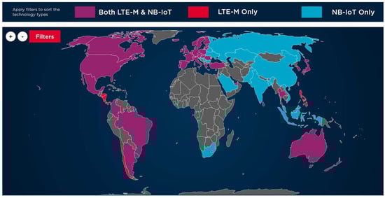
Figure 2.
Global IoT cellular coverage map of the GSM Association [24].
BLE Mesh Networks enable flexible and reliable communications for low-power Internet of Things (IoT) devices thanks to several key features explained below [25].
BLE Mesh networks can self-organize without a central control point. Devices can communicate directly with each other, extending the network range without relying on a single central device. They are highly scalable and can handle a large number of connected devices, allowing for the addition of new devices without compromising network functionality. BLE is designed to consume minimal power, allowing battery-powered devices to operate for long periods without frequent recharging. The mesh topology enables each device to act as both a node and a relay, allowing data transmission through multiple nodes and improving coverage and connection reliability. The mesh network offers multiple communication paths, allowing data to find alternative routes in case a node encounters issues or becomes disconnected. The network can adapt to environmental changes, automatically adjusting communication paths to maintain a reliable connection.
These characteristics make BLE Mesh networks an attractive solution for various IoT scenarios and applications that require efficient and reliable connectivity for a large number of devices, including dry container monitoring.
At the conclusion of this section, we mention the international standardization initiatives that tracking devices for dry containers should adhere to in order to have better chances of success in the highly standardized field of multimodal logistics.
ISO 18625 [26] guides the requirements (operational and otherwise) for a system and its enabling devices used to track, monitor and/or report the status of the container, referred to as the Container Tracking and Monitoring System (CTMS). With a tiered approach, the standard specifies (a) a set of requirements for transferring information to and from a container tracking device to/from an automatic data processing system; (b) functional requirements necessary to ensure consistent and reliable operation of the CTMS; (c) features to inhibit malicious or unintentional alteration and/or deletion of the information content of the CTMS; (d) compliance to ISO 18185 [27] regarding the environmental characteristics of operating devices.
In September 2020, the DCSA published IoT standards for gateway connectivity interfaces for the global container shipping industry [28]. These standards are designed to enable industry-wide interoperability between IoT devices (including “smart containers”) and the supporting network infrastructure. The standards in this release align internal radio communication protocols for IoT gateways, addressing the network connectivity requirements for reefer containers, dry containers, and the RFID registration of these containers. This publication is intended to serve as the foundational work to enable interoperability at the gateways’ internal radio interface level for the defined use cases. It would also be the basis for future IoT standard releases from DCSA, which, however, have not yet occurred although planned.
Lastly, intending to standardize the fundamental information provided across the carrier liner domain, DCSA provided the third version interface standard for track and trace in March 2023. This document also intends to facilitate discussions around the exchange of track and trace data between the different counterparts involved in the shipment(s) and should lead to better accountability and traceability of activities concerning the shipment of goods [29].
3. Materials and Methods
According to the implementation program of the 5G SENSOR@SEA project [1], this section presents the materials and methods employed for the design activity of the prototype of the CTD. They are summarized as follows:
- Identification of the CTD technical requirements and functions;
- Definition of the CTD’s architecture, including the specification of the employed radio transceivers and the internal interfaces;
- Specification of the hardware design;
- Specification of the software design.
3.1. CTD’s Requirements and Functions
The CTD is a device that can be installed on general-purpose maritime dry containers. It is a device compliant with ISO/TS 18625 [22], ISO 18185-3 [23], and ISO 668 [30] standards based on low-cost and low-power consumption microprocessors suitable for IoT. Its function is to monitor the status of containers in real-time, regardless of location (land, near sea, open sea), through sensors (temperature, motion, pressure, humidity, door opening, position) and two types of TX/RX radio interfaces: NB-IoT and BLE Mesh, in addition to GNSS for position and timing. The NB-IoT interface allows the CTD to connect to a base station installed onboard the ship (Open Sea) or to the land cellular networks (near sea and terrestrial scenario). On the other hand, the BLE Mesh interface will allow CTDs to establish mesh networks when the NB-IoT cellular connectivity is available only for some CTDs, located in the area reached by the cellular signal, but not for those nearby. In this situation, through the mesh network, it will be possible to propagate data from a CTD, in provisioned sensor node configuration, to the CTD hooked to the NB-IoT cell in NB-IoT visibility, which assumes the role of the gateway (see Figure 3). Considering the conventional stacking methods of containers on ships and yards, we found that usually, the maximum number of containers stacked is 5. For this reason, in the 5GT System, the maximum number of nodes for each BLE Mesh has been limited to 5 as per the design. The following sections will present the implementation of the first CTD prototype, and to demonstrate its mesh functionality, 5 nodes will be put into communication.
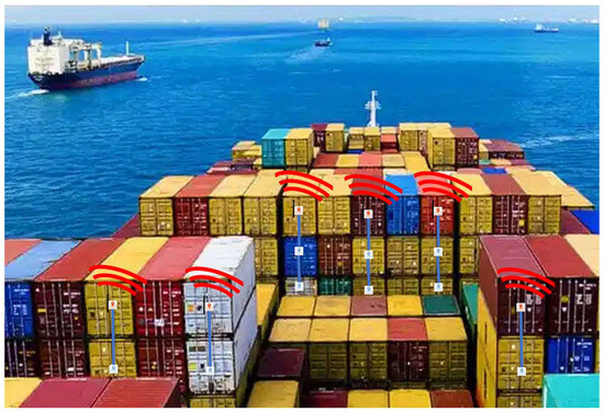
Figure 3.
Representation of CTDs on the ship: devices at the top of the container stack perform as the NB-IoT/BLE Mesh Gateway, and those below are nodes of BLE Meshes.
Thus, the CTD is a battery-powered device with sensors, NB-IoT radio, BLE Mesh radio, and GNSS, capable of operating in opportunistic ways as needed, such as:
- Monitor and trace unit with NB-IoT connectivity;
- Monitor and trace unit, provisioner of a BLE Mesh network and NB-IoT gateway;
- Monitor and trace unit, the provisioned device of a BLE Mesh network (source node or relay).
- Although, from a functional point of view, these three roles are distinct, from the HW point of view, the CTD has exactly the same elements, both when it performs the function of a mesh network node, when it performs the role of GW and when it just transmits sensing data via NB-IoT. It is, therefore, the same device that contains all the elements to perform all the functions, as described in the next subsection.
3.2. CTD’s System Architecture
As can be seen from the CTD’s architecture in Figure 4, there are essentially 5 HW blocks:
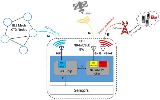
Figure 4.
The architecture of CTD as GW between the BLE Mesh and the NB-IoT cellular networks.
- The microprocessor (MCU) controls all the system functions, also embedding the chip for BLE Mesh radio;
- The modem provides NB-IoT cellular connectivity and GNSS data reception;
- The set of sensors (temperature, humidity, pressure, 3-axis motion for movement and shock detection, container door opening);
- The set of antennas (cellular, BLE, GNSS);
- The power supply battery pack (not shown in Figure 4).
The CTD provides sensing and position data to a OneM2M compliant [2] platform in the cloud through the NB-IoT cellular network. The GNSS receiver provides position and timing data, the embedded sensors provide instant value data for temperature, humidity, pressure, 3-axis motion for movement and shock detector, and container door opening. This information is transmitted to the OneM2M compliant platform periodically, with a time interval selected according to the intended use, or when an “alarm event” occurs, notably when some physical sensing data are out of the limits set by the user of the CTD.
According to the architecture shown in Figure 4, the CTD also operates as a gateway between the other nodes of a BLE Mesh network (left in blue) and the NB-IoT cellular network. The information provided to the cloud platform is of the same type as the previous case, but it is referred to as a sensor node of the mesh network.
The interfaces supported by each diagram block are described in Table 1 as follows (see Figure 4 for the names).

Table 1.
Interfaces of the CTD.
3.3. Hardware Design
This subsection shows the CTD’s electronic features used in order to meet the function requirements specified in Section 3.1.
A preliminary analysis of the characteristics of development platforms most suitable for prototyping the device of interest has been carried out. Starting from the IoT device prototyping platforms available off-the-shelf, two possible approaches have been identified:
- Using Nordic devices and, more precisely, the Nordic Thingy:91 (already equipped with BLE, NB-IoT and GPS radios and a set of sensors) for the SW prototyping and the NRF9160 DK (which has the same processors as the Thingy:91) for the HW prototyping (adding sensors, etc.);
- Using devices with ESP32 as the main controller and BLE Mesh coupled to a Quectel BG 95 cellular modem. For this approach, the ESP32 dev kit from Adafruit (HUZZAH32 ESP32 FEATHER STACK HDR) combined with a compatible Quectel BG95 modem shield has been selected.
The information and specifications on the datasheets were used to compare the two approaches concerning their ability to meet the functional requirements.
From this initial analysis, it was found that both approaches are feasible, in principle, although each has advantages and disadvantages. In general, Nordic is less power-demanding but more expensive, whereas ESP32 + Quectel is cheaper but more power-demanding. Then, the devices for both approaches were purchased (see Figure 5 and Figure 6) and preliminary tests were performed: (1) set up the NB-IoT communication; (2) set up BLE Mesh.
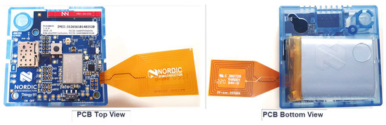
Figure 5.
The purchased Nordic Thingy:91 prototyping platform [31].
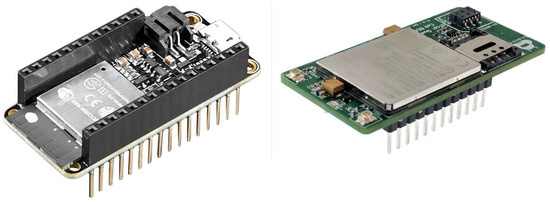
Figure 6.
The purchased ESP32 prototyping platform (left), with Quectel BG95 shield (right).
Regarding NB-IoT communication, using both Nordic and ESP32 + Quectel BG95 with SIM cards provided by TIM/Olivetti, it was possible to send position and sensor data to the cloud. It is important to emphasize that the CTD is SIM agnostic, as standard cellular technology is integrated into the system; notably, the authors also tested SIMs from other mobile virtual network operators (e.g., 1NCE—DE, Telenor—NO, Arkessa—UK) offering NB-IoT SIMs that work globally. The market is evolving rapidly in this regard; other companies are claiming global roaming agreements, including TIM, ORBCOMM, Things Mobile and even Satelliot.
Regarding BLE Mesh, with the Nordic approach, it was impossible to implement a BLE Mesh network. We have found that although the nRF52840 chip is included in the list of those that support BLE Mesh, in reality, this is not allowed in the current version of the firmware that Nordic makes available for the Thingy:91, nor is an upgrade planned.
On the other hand, with the ESP32, it was possible to set up a BLE Mesh network. We verified that once the mesh was established, it was possible to (a) send data requests from the provisioner node toward the source sensor nodes and (b) send sensor data from the source node toward the provisioner/GW node.
The insights we received from comparing the two approaches can be summarized as follows.
- Nordic approach: BLE Mesh is not feasible with Nordic Thingy:91/NRF9160 DK. On this route, it is necessary to address the Nordic Thingy:53/nRF5340 DK (new product, not yet available on the market and not yet fully documented). An NB-IoT modem will need to be integrated into this platform (which, however, is already present on the Nordic Thingy:91).
- ESP32 + Quectel BG95 approach: we built a BLE Mesh network with the SGI sensor node model; we configured the BG95, tested the connection to the TIM cellular network and successfully sent JSON messages to the ICON platform (TIM/Olivetti).
In summary, the preliminary tests showed that the ESP32 + Quectel BG95 approach is suitable for the CTD prototype development. The Nordic approach certainly remains valid, in perspective, but requires further developments of new products that are not yet consolidated.
As shown in Figure 7, the final choice for designing the CTD is to use the ESP32-WROOM-32 module as the board controller and application processor. It is a generic multi-radio module that targets a wide variety of applications, including low-power sensor networks.
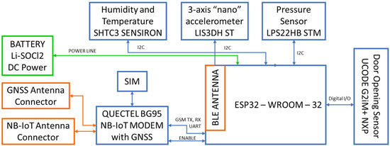
Figure 7.
CTD block diagram.
At the core of this module is the ESP32-D0WDQ6 chip. The chip embedded is designed to be scalable and adaptive. Two CPU cores can be individually controlled, and the CPU clock frequency is adjustable from 80 MHz to 240 MHz. The chip also has a low-power co-processor that can be used instead of the CPU to save power while performing tasks that do not require much computing power, such as monitoring peripherals. ESP32 integrates a rich set of peripherals, including those needed for our project: UART and I2C.
The electrical characteristics are suitable for use in a harsh environment such as the marine one [32].
The ESP32-WROOM-32 implements the “ESP-BLE-MESH” according to the latest Bluetooth® Mesh Profile v1.0.1. As can be read in the certificate “ESP BLE Mesh is Espressif’s implementation of the SIG Bluetooth Mesh. It supports all SIG Bluetooth Mesh Features, Server Models and Client Models. It is a portable and scalable embedded software solution that operates with Espressif’s Bluetooth ICs family” [33]. Built on top of the Zephyr Bluetooth Mesh stack, the ESP-BLE-MESH implementation supports device provisioning and node control. It also supports such node features as proxy, relay, low-power and friend.
To bring the NB-IoT and the GNSS connectivity to the main module, a compatible shield is adopted. It is based on the BG95-M3 Quectel modem [34]. It is an embedded IoT (LTE Cat M1, LTE Cat NB2 and EGPRS) wireless communication module with ultra-low power consumption. It provides data connectivity on LTE-TDD/LTE-FDD/GPRS/EDGE networks and supports half-duplex operation in LTE networks. It also provides GNSS functionality to meet customers’ specific application demands. Two U.FL connectors are used for internal or external Antennas (LTE and GNSS). The shield supports a nano-SIM card to be inserted into the Hinged Lid SIM Card Holder type located at the top of the PCB. All SIM card traces are ESD-protected. The network indication LED, located in the center of the edge of the board lets us observe the modem network status. TPS63020 Buck-Boost Converter is used to power the modem, so the shield is fully functional even with input voltage dropping down to 3.3 V. DC/DC. The output voltage is also used to power LDO, which provides 3.3 V. DC for the level translators, Open-Drain (OD) logic IC and active GNSS antenna to be connected. The shield provides 3.3 V. DC power for the active GNSS antenna. The extended operating temperature range of −40 °C to +85 °C makes it suitable for harsh environments.
3.4. Software Design
The objective of this subsection is to describe the CTD software (v0) functionalities for accomplishing both maritime and terrestrial scenario operations.
The SW was developed for CTD with ESP32 + Quectel BG95 + sensors to enable the following functions for the intended use:
- Monitoring and tracking unit sending UDP packets to a cloud OneM2M compliant platform.
- Monitoring and tracking unit, provisioner of a BLE Mesh network from the device, which is also a gateway for NB-IoT/BLE Mesh networks.
- Monitoring and tracking unit, a provisioned device of a BLE Mesh network (source node or relay) for the device with NB-IoT off.
- Monitoring and tracking unit, a gateway for NB-IoT/BLE Mesh networks, sending packets to the cloud OneM2M compliant platform, with the information generated from the sensor mesh nodes.
The activity consisted of developing the SW to establish the connection with the NB-IoT cellular network and sending UDP packets with JSON payload. Furthermore, the SW for enabling the gateway function NB-IoT/BLE Mesh has been developed in such a way that the sensor data from a source node of the BLE Mesh is used to fill the content of the JSON payload to be transmitted to the ICON platform.
Regarding the BLE Mesh, the activity consisted of adapting the SGI sensor model [35] in order to provide the needed functions in two cases. Notably, once the mesh is established, it is possible to:
- (a)
- Send data requests from the provisioner/gateway node toward the source sensor nodes,
- (b)
- Or send sensor data from the source node towards the provisioner/gateway node.
The firmware allows managing both event-driven and periodic data transmission, with custom thresholds and time intervals set by the user. Furthermore, the firmware manages the energy-saving functions to make the battery last.
The SW is implemented using the Real-time Operating System (RTOS) on ESP32. The algorithm for the communication and data transmission is illustrated by the flowchart given in Figure 8.
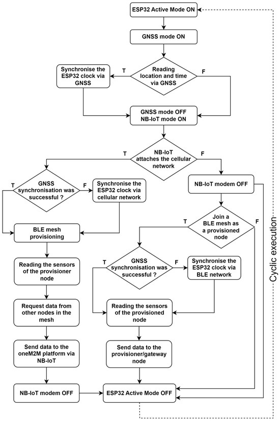
Figure 8.
Flowchart of the algorithm instantiated for CTD’s communications.
The microcontroller firmware implements the following features:
- Reading the temperature, humidity, and pressure sensors;
- Reading the accelerometer in order to identify significant movements and shocks;
- Reading location (geographic coordinates, via GNSS);
- Updating the time (via either GNSS, NB-IoT, or BLE Mesh);
- Enabling communication (NB-IoT and/or BLE);
- Provision (or join) a BLE mesh network;
- Sending the read data to the ICON cloud platform; this can be achieved directly via NB-IoT or other BLE mesh nodes (Relay and Gateway).
The device performs all these operations periodically, the interval of which is configurable. When not engaged in these tasks, the firmware puts all components in the lowest supported and usable power mode to maximize battery life.
Thus, data are sent periodically during a transmission window where, depending on the connectivity status of the radio interfaces, the device can assume the following roles:
- NB-IoT terminal: device that is under NB-IoT network coverage and sends data to the ICON platform via the NB-IoT network;
- Mesh node: device without NB-IoT network coverage but which is part of a BLE mesh network; it sends its data to another node in the mesh network so that it is propagated to the gateway node; each node in the mesh network also acts as a bridge (Relay) for other neighboring nodes, forwarding their data;
- Gateway NB-IoT/BLE Mesh: a device that is both under the coverage of the NB-IoT network and part of the BLE mesh network; it sends both its own data and the data of mesh nodes connected to it to the platform.
The role of the device is dynamic and determined by operational conditions. The role has no impact on either the hardware or the firmware of the CTDs, which are all the same.
In order to allow all nodes to send their data periodically, they awaken “simultaneously” and, if necessary, establish a mesh network (or reuse the previous one, if available). The simultaneity of awakening is related to the accuracy of the internal clock. The wake-up window is, therefore, extended to compensate for the drift of individual device clocks.
To synchronize its clock, each CTD has three sources, which it uses with decreasing priority, as shown:
- GNSS signal;
- NB-IoT signal;
- BLE mesh network.
4. Results
As mentioned in Section 1, a Proof-of-Concept (PoC) prototype CTD (see Figure 9) was set up with the purpose of achieving the following primary objectives associated with this applied research project:
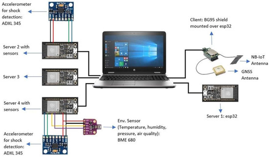
Figure 9.
CTD Proof-of-Concept setup [36].
- Verify the instantiation of NB-IoT communication to the OneM2M-compliant platform;
- Verify the interfacing of the sensors with the MCU;
- Verify the provisioning of a BLE Mesh network and sensor data exchange with the gateway node;
- Verify the size of the battery pack by measuring the power consumption.
The setups shown in Figure 9 have been implemented for testing purposes in different scenarios, consisting of five Huzzah ESP32 feather boards with ancillary elements as needed for the tests.
Ideally, all the ESP32 boards should have had a Quectel BG95 shield mounted on top of them, so that in the final CTD’s implementation, any one of them can send the data to the cloud if the cellular connectivity is available, but since the test goals are to verify the BLE Mesh capability, only one BG95 shield was used. It was only installed on the provisioner/gateway node (which in Figure 9 is called “client” so that once the mesh is provisioned, the BLE Mesh “client” node fetches the data from the BLE server nodes) that can send data to the cloud. Furthermore, each ESP32 board should be connected to BME680 and ADXL 345 sensors to measure environmental data and shock detection, respectively, of each individual container. Nevertheless, for the PoC implementation, only one BME 680 and only two ADXL 345 were available; therefore, only one of the BLE Mesh nodes (called servers in Figure 9) has BME 680 and ADXL 345, and one of the BLE Mesh nodes has just ADXL 345. Furthermore, in the PoC setup, the battery has not been used. The boards are powered using the USB ports of the laptop. Since the door sensor was not available, it has not been used in the PoC setup.
The results of each test are presented in the following subsections.
4.1. NB-IoT Communication and Sensor Integration
The test consisted of only one device integrating both the sensors: the GNSS and the NB-IoT module publishing data to the oneM2M platform on the cloud. Regarding Figure 9, the test was essentially conducted by equipping ‘Server 4’ with the BG95 shield and NB-IoT and GNSS antennas. The ICON oneM2M-compliant TIM cloud platform [37] was used to monitor the data in the cloud. Figure 10 shows the dashboard of the TIM ICON cloud services that are used for this project. Data in the cloud can be viewed by navigating to the resource tree and checking the data in the inbox corresponding to the MSISDN code of the SIM put into the device. Figure 11 shows the CTD’s data on the TIM ICON OneM2M compliant platform, hence verifying the NB-IoT connectivity, the sensors and the GNSS operation.
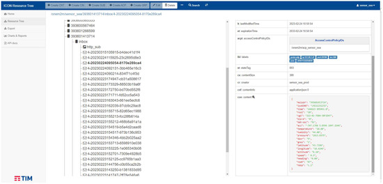
Figure 10.
Dashboard of the ICON OneM2M compliant platform.
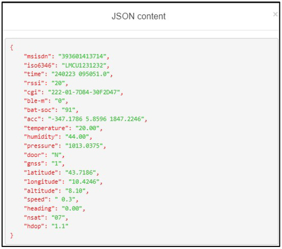
Figure 11.
Data published to the ICON OneM2M-compliant platform.
4.2. BLE Mesh Network
This test shows the verification of the provisioning and communication of the BLE Mesh network, consisting of five nodes. Referring to Figure 9, one of the nodes was made the provisioner/client of the mesh, and all other four nodes were made the provisioned/server. The provisioner/client node is also the gateway for the NB-IoT/BLE Mesh networks, with the BG95 shield.
The test showed that the device with the BG95 shield, after joining the NB-IoT cellular network, was able to provision a BLE Mesh network and forward messages to the ICON platform from the provisioned/server nodes. The devices that cannot connect to the NB-IoT cellular network were provisioned as BLE Mesh nodes and published messages to the ICON via the gateway.
Figure 12 shows an example of how the data produced by the devices are monitored. Figure 13 shows the successful provisioning message displayed on the console of the client nodes. Figure 14 shows, as an example, the monitoring console of the client mesh node, with the payload of the data transmitted by the server; in Figure 15, the payload as published to the ICON platform via the client gateway node is shown.
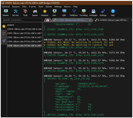
Figure 12.
Monitoring console of the devices [36].
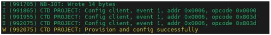
Figure 13.
Provisioning of BLE Mesh server nodes by the client [36].
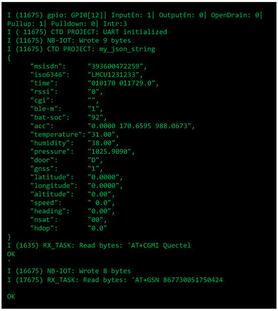
Figure 14.
Console output showing data produced by a BLE server mesh node [36].
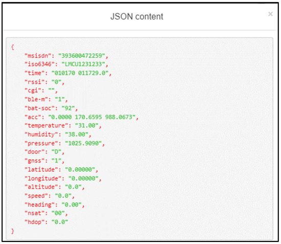
Figure 15.
Data published to the ICON platform from a BLE server mesh node [36].
4.3. Current Consumption Measurement
For current consumption measurement, the Nordic PPK2 module was used. For monitoring the measurements, the Power Profiler Kit App with nRF Connect for Desktop software (v3.4.3) was used. The practical setup is sketched in Figure 16.
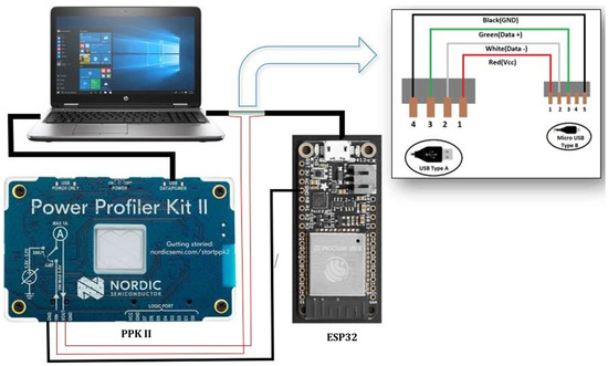
Figure 16.
Power consumption measurement setup [36].
There are two modes in the application, i.e., Source Meter and Ampere Meter. In Source Meter mode, the PPK2 device acts as a battery source to power up the development board. In the Ampere Meter mode, the PPK2 device acts as an ammeter to measure the current. Since the goal of the task was to measure the current consumption, the Ampere Meter mode was used. In the application, the sampling rate can also be changed. It should be noted that more samples imply more accurate data but more consumption of resources. Since spending the resources was not an issue, the maximum sampling rate has been selected, i.e., 100 kSPS (kilo-Samples Per Second). Sampling time can also be changed in the application. Since the scenario for the prototype is that the CTD will transmit data for 5 min, 4 times a day, the sampling time is kept at approximately 5 min. This will only capture the power consumption in the active mode of the device, and from that, the behavior of the device can be estimated over one year.
Figure 17 shows as an example the current measurement over one minute, for the gateway node with all interfaces active. During this period, two transmissions with NB-IoT and BLE Mesh occur, lasting about 15 s each. Figure 18 shows the current consumption when the ESP32 processor is running in active mode with the BLE radio turned on, transmitting periodic beacons. Figure 19 shows the current consumption when using the BLE Mesh radio channel to transmit sensor data.
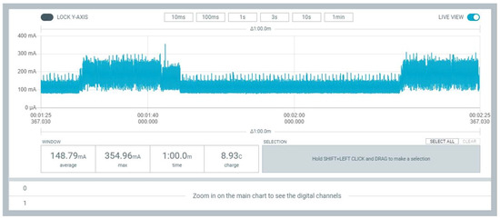
Figure 17.
Current consumption with NB-IoT, BLE Mesh, sensors and GPS turned on [36].
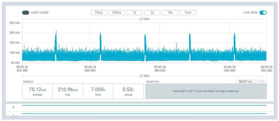
Figure 18.
Current consumption without sensors ESP32 in active mode with BLE turned on, transmitting periodical beacons [36].
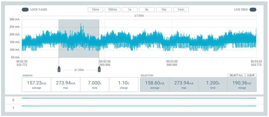
Figure 19.
Current consumption during BLE Mesh usage [36].
5. Discussion
This section discusses the results of the tests described in Section 4, with a special focus on the power consumption of the CTD. After verifying that the firmware is capable of correctly handling the various functions of the device, namely NB-IoT transmission to the OneM2M-compliant platform for sensor data (Figure 10 and Figure 11), BLE Mesh network provisioning by the provisioner/client node (Figure 12 and Figure 13), and data transmission to the OneM2M-compliant platform, by the provisioner node in NB-IoT/BLE Mesh gateway mode (Figure 14 and Figure 15), specific current measurements were taken to size the battery pack.
Section 4.3 explores the power consumption of the CTD in various scenarios through multiple tests. The first test measures the current consumption of the device with ESP32 in active mode with the BLE radio turned on but no sensors attached. The result is depicted in Figure 18. The active mode current consumption for ESP32 is about 75mA. Spikes indicate that the device periodically transmits beacons via the BLE Mesh radio. This fits fine with the current consumption values declared in the ESP32 datasheet [32]. Figure 17 illustrates the graph of the tests in which all the modules were installed and were active. The interval of this window is one minute. It can be seen that the CTD is performing the cycle of mesh provisioning, sensor reading and transmitting the data to the cloud twice a minute. During the time interval of 13 s, the current consumption increased significantly due to the activation of all the radios, including the GNSS antenna. This information can be used to verify the current consumption calculations presented below and to propose a battery pack suitable for the intended use. Figure 19 shows the energy consumption during data transmission via BLE Mesh; the average consumption over 7 s is slightly higher than the value of a full cycle of 60 s (with NB-IoT and GNSS on), as expected, but the peak value is lower because, in the full cycle, the peaks are caused by the NB-IoT/GNSS module operations.
Since the test shown in Figure 17 contains all the modules in the active mode, it is taken as the worst-case scenario for sizing the battery pack. As can be seen, the data transmission window is large, approximately 13 s, and occurs twice a minute. On the other hand, the data are being read from the sensors for approximately 34 s between the transmissions. When the data are being sent to the cloud, the pulses reach the maximum current of approximately 350 mA and an average value of 215 mA. Hence, the worst-case scenario would be when the device constantly consumes an average of 215 mA, when it is in transmission mode, while when the device is reading the data from the sensors and not transmitting it to the cloud, the CTD consumes approximately 150 mA on average. Therefore, in a minute, the CTD is in transmission mode two times for 13 s each and consumes 215 mA and then obtains the data from the sensors for 34 s, consuming 150 mA. With this information, the total current consumption in a minute can be calculated, and building on that, the current consumption of CTD in one year can be estimated to verify if the proposed battery pack is viable. According to the intended use, the CTD will transmit data to the cloud four times a day, and each transmission window is large, i.e., 5 min. We refer to this as “active mode”. When the CTD is not in active mode, the processor turns off all radios and reduces its operations, going into “deep-sleep mode”. The calculations are carried out according to the aforementioned intended use and are presented in the following equations:
When the device is in sleep mode, all the radios are turned off, and only ESP32 is powered in deep-sleep mode, notably only the Real-Time Clock (RTC) memory and RTC peripherals are powered up, Bluetooth connection data are stored in the RTC memory, and the ultra-low power coprocessor is functional. From the ESP32 datasheet [32], we find that the current consumption in this case is 150 µA. Let us calculate the period for the CTD in deep-sleep mode in 1 day:
thus, the charge consumed in one day in deep-sleep mode is:
The total charge consumed in one day by the CTD is given by the sum of Equations (4) and (6). Finally, we express in Equations (7) and (8) the total charge required for one year (365 days) of operation in mAh (milliampere-hour) and the required battery capacity, including 20% leakage:
Hence, proposing a battery pack of 27,000 mAh (consisting, for example, of two LSH20 SAFT batteries [38]) is viable even in the worst-case scenario for the intended use of the CTD.
6. Conclusions
The work presented here shows the scope, the methods and the results of applied research to develop a monitoring and tracking device for dry containers. This task is part of the so-called 5GT system employing a novel combination of telecommunication technologies, notably 5G, Satcom, NB-IoT and BLE mesh, to realize a ubiquitous and massive real-time monitoring service of intermodal containers. Starting from a preliminary phase, in which the state-of-the-art technologies, research approaches, industrial initiatives and developing standards were investigated, the following sections showed how a prototype version of the Container Tracking Device (CTD) has been designed, developed and verified as the first fundamental step. This enabled the subsequent industrial realization of the devices used in the final assessment of the 5G SENSOR@SEA [1] project in an operational environment, which will be presented in a future article currently in preparation.
The tests performed showed that the firmware is capable of handling the various functions of the device. Furthermore, by measuring the power consumption measurements of the CTD in different operating modes, it was possible to suggest the size of the battery pack. Different operating modes of the device were tested, showing battery needs that can be assumed as the baseline for future improvements.
Future works can be addressed to further optimize the power consumption. Energy savings can be achieved by optimizing software, especially in the management of radio transmissions and by introducing power systems with rechargeable batteries.
More generally, in the subject of “smart container” systems, important developments are expected to be achieved with the integration of low earth orbit satellite communication technologies and 6G cellular networks for the massive development of the Internet of Things.
Author Contributions
Conceptualization, M.F., M., S.N. and P.P.; methodology, M.F., M., S.N. and P.P.; software, M. and M.F.; validation, M.; formal analysis, M.F.; investigation, M.F., M. and S.N.; resources, M.F., M., S.N. and P.P.; data curation, M.F. and M.; writing—original draft preparation, M.F.; writing—review and editing, M.F., M., S.N. and P.P.; visualization, M.F.; supervision, M.F.; project administration, S.N.; funding acquisition, S.N. All authors have read and agreed to the published version of the manuscript.
Funding
This work was funded by the European Space Agency (ESA) through the 5G SENSOR@SEA project (contract no. AO/1-10285/20/NL/AF). The 5G SENSOR@SEA project was carried out under the ARTES 5G/6G Strategic Programme Line and funded by ESA.
Data Availability Statement
The original contributions presented in the study are included in the article, further inquiries can be directed to the corresponding author.
Acknowledgments
We would like to thank the ESA Telecommunication Systems engineer Technical Officer for his valuable technical contract management during the 5G SENSOR@SEA project and the CNIT’s contract employees Akeem Safiriyu and Asim Zulfiqar for their practical contribution to the setup of the PoC. Special thanks to TIM colleagues Paolo Scalambro and Piero Cena for supporting the use of ICON as part of the 5G SENSOR@SEA project.
Conflicts of Interest
The authors declare no conflicts of interest. The funders had no role in the design of the study; in the collection, analyses, or interpretation of data; in the writing of the manuscript; or in the decision to publish the results. The view expressed herein can in no way be taken to reflect the official opinion of the European Space Agency.
References
- 5G SENSOR@SEA. Available online: https://connectivity.esa.int/projects/5g-sensorsea (accessed on 20 February 2024).
- OneM2M Sets Standards for The Internet of Things & M2M. Available online: https://www.onem2m.org/ (accessed on 20 February 2024).
- Noto, S.; Gharbaoui, M.; Falcitelli, M.; Martini, B.; Castoldi, P.; Pagano, P. Experimental Evaluation of an IoT-Based Platform for Maritime Transport Services. Appl. Syst. Innov. 2023, 6, 58. [Google Scholar] [CrossRef]
- Yang, G.-H.; Xu, K.; Li, V.O.K. Hybrid Cargo-Level Tracking System for Logistics. In Proceedings of the 2010 IEEE 71st Vehicular Technology Conference, Taipei, Taiwan, 16–19 May 2010; pp. 1–5. [Google Scholar] [CrossRef][Green Version]
- Choi, H.; Baek, Y.; Lee, B. Design and implementation of practical asset tracking system in container terminals. Int. J. Precis. Eng. Manuf. 2012, 13, 1955–1964. [Google Scholar] [CrossRef]
- Kavuri, S.; Moltchanov, D.; Ometov, A.; Andreev, S.; Koucheryavy, Y. Performance Analysis of Onshore NB-IoT for Container Tracking During Near-the-Shore Vessel Navigation. IEEE Internet Things J. 2020, 7, 2928–2943. [Google Scholar] [CrossRef]
- Xu, S.; Li, J.; Cao, W.; Zhang, S. Design and Implementation of Container Global Monitoring Device Based on Low-Orbit Satellite Communication Module. J. Phys. Conf. Ser. 2020, 1617, 012021. [Google Scholar] [CrossRef]
- Monzon Baeza, V.; Ortiz, F.; Herrero Garcia, S.; Lagunas, E. Enhanced Communications on Satellite-Based IoT Systems to Support Maritime Transportation Services. Sensors 2022, 22, 6450. [Google Scholar] [CrossRef] [PubMed]
- Jakovlev, S.; Jusis, M.; Eglynas, T.; Voznak, M.; Tovarek, J.; Partila, P. Application of a Mobile LoRaWAN System in a Container Terminal to Collect Sensory Data. In Proceedings of the 2021 13th International Congress on Ultra Modern Telecommunications and Control Systems and Workshops (ICUMT), Brno, Czech Republic, 25–27 October 2021; pp. 22–26. [Google Scholar] [CrossRef]
- Bretschneider, T.; Thai Dung, N. Container tracking via AIS satellites. In Proceedings of the Asian Conference on Remote Sensing, Nay Pyi Taw, Myanmar, 27–31 October 2014. [Google Scholar]
- Chung, Y.; Ahn, J.Y.; Du Huh, J. Experiments of A LPWAN Tracking(TR) Platform Based on Sigfox Test Network. In Proceedings of the 2018 International Conference on Information and Communication Technology Convergence (ICTC), Jeju, Republic of Korea, 17–19 October 2018; pp. 1373–1376. [Google Scholar] [CrossRef]
- E-SealTM Tracking System and Configurations, Avante International Technology, Inc. (Blog). Available online: https://www.avantetech.com/e-seal-tracking-system-and-configurations (accessed on 20 February 2024).
- Tetis Container Tracking ISO Standard Starcom GPS Global Solutions, Starcom GPS Global Solutions (Blog). Available online: https://www.starcomgpsglobal.com/tetis-family-2 (accessed on 20 February 2024).
- Ryszard, K.M. Electronic Container Tracking System as a Cost-Effective Tool in Intermodal and Maritime Transport Management. Econ. Altern. 2015, 1, 40–45. [Google Scholar]
- Traxens Box. Available online: https://uic.org/events/IMG/pdf/traxens.pdf (accessed on 20 February 2024).
- Digital Container Shipping Association (DCSA). Available online: https://dcsa.org (accessed on 20 February 2024).
- Traxens New IoT Device. Available online: https://www.traxens.com/press/traxens-new-iot-device-leads-smart-container-requirements-for-decarbonising-shipping (accessed on 20 February 2024).
- Traxens—Permanent IoT Container Trackers. Available online: https://www.traxens.com/products/permanent-container-tracker (accessed on 20 February 2024).
- About Live Position—Hapag-Lloyd. Available online: https://www.hapag-lloyd.com/en/services-information/cargo-fleet/container-monitoring/hapag-lloyd-live-dry.html (accessed on 20 February 2024).
- Edge, Nexxiot (Blog). Available online: https://nexxiot.com/edge (accessed on 20 February 2024).
- 3GPP Organizational Partners. Technical Specification Group Services and System Aspects; Feasibility Study on New Services and Markets Technology Enablers for Massive Internet of Things (Stage 1, Release 14); The 3rd Generation Partnership Project; 3GPP, TR 22.861 V14.1.0; 3GPP Organizational Partners: Valbonne, France, 2016. [Google Scholar]
- Mwakwata, C.B.; Malik, H.; Mahtab Alam, M.; Le Moullec, Y.; Parand, S.; Mumtaz, S. Narrowband Internet of Things (NB-IoT): From Physical (PHY) and Media Access Control (MAC) Layers Perspectives. Sensors 2019, 19, 2613. [Google Scholar] [CrossRef] [PubMed]
- Gharbaoui, M.; Martini, B.; Noto, S.; Ruscelli, A.L.; Pagano, P.; Castoldi, P. Experimenting SDN/NFV Solutions for Flexible Maritime Transport & Logistics (T&L) Services. In Proceedings of the 2023 IEEE Conference on Network Function Virtualization and Software Defined Networks (NFV-SDN), Dresden, Germany, 7–9 November 2023; pp. 27–33. [Google Scholar] [CrossRef]
- Mobile IoT Deployment Map, Internet of Things (Blog). Available online: https://www.gsma.com/iot/deployment-map (accessed on 20 February 2024).
- Hernández-Solana, Á.; Pérez-Díaz-De-Cerio, D.; García-Lozano, M.; Bardají, A.V.; Valenzuela, J.-L. Bluetooth Mesh Analysis, Issues, and Challenges. IEEE Access 2020, 8, 53784–53800. [Google Scholar] [CrossRef]
- ISO/TC 104/SC 4; ISO/TS 18625:2017 Freight Containers Container Tracking and Monitoring Systems (CTMS): Requirements. ISO: Geneva, Switzerland, 2017.
- ISO/TC 104/SC 4; ISO 18185-3:2015 Freight Containers Electronic Seals Part 3: Environmental Characteristics. ISO: Geneva, Switzerland, 2015.
- DCSA-P2-Gateway-Connectivity-Interfaces-Standards_v1.0_FINAL. Available online: https://dcsa.org/wp-content/uploads/2020/09/DCSA-P2-Gateway-Connectivity-Interfaces-Standards_v1.0_FINAL.pdf (accessed on 20 February 2024).
- Salesforce. Available online: https://dcsa.my.salesforce.com/sfc/p/#2o000000YvHJ/a/7T0000019gxv/Zkn8hOG14OtuFidEp49rPyT4icsSWDniFbiqoULtdZY (accessed on 20 February 2024).
- ISO/TC 104/SC 1; ISO 668:2020 Series 1 Freight Containers—Classification, Dimensions and Ratings. ISO: Geneva, Switzerland, 2020.
- Thingy:91 Multisensor Prototyping Kit—Nordic|Mouser. Available online: https://www.mouser.it/new/nordic-semiconductor/nordic-thingy-91 (accessed on 20 February 2024).
- Esp32_datasheet_en. Available online: https://www.espressif.com/sites/default/files/documentation/esp32_datasheet_en.pdf (accessed on 20 February 2024).
- ESP-BLE-MESH Is Now Fully Certified by Bluetooth-SIG|Espressif Systems. Available online: https://www.espressif.com/en/news/ESP_BLE_MESH_SIG_Certified (accessed on 20 February 2024).
- LPWA BG95-M3 Mini PCIe, Quectel. Available online: https://www.quectel.com/product/lpwa-bg95-m3-mpcie (accessed on 20 February 2024).
- Mesh Model, Bluetooth® Specification, Revision v1.1 12/09/2023. Bluetooth SIG Mesh Working Group. Available online: https://www.bluetooth.com/specifications/specs/mesh-model-1-1 (accessed on 20 February 2024).
- Misal. Development of a Multi Radio Container Tracking Device for Global Logistics Services. In Master Degree on Photonic Integrated Circuits, Sensors and NETworks (PIXNET Erasmus+ Program); Scuola Superiore Sant’Anna: Pisa, Italy, 2022. [Google Scholar]
- ICON Login. Available online: https://icon-lab.tim.it/web (accessed on 20 February 2024).
- LSH 20. Available online: https://t.ly/Ut4nt (accessed on 20 February 2024).
Disclaimer/Publisher’s Note: The statements, opinions and data contained in all publications are solely those of the individual author(s) and contributor(s) and not of MDPI and/or the editor(s). MDPI and/or the editor(s) disclaim responsibility for any injury to people or property resulting from any ideas, methods, instructions or products referred to in the content. |
© 2024 by the authors. Licensee MDPI, Basel, Switzerland. This article is an open access article distributed under the terms and conditions of the Creative Commons Attribution (CC BY) license (https://creativecommons.org/licenses/by/4.0/).