Article

Seismic Assessment and Restoration Strategies for Cultural Heritage Buildings in the Neapolitan Area: The Case of Villa Vannucchi

by
Antonio Formisano
* and
Giovanna Longobardi
Department of Structures for Engineering and Architecture, School of Polytechnic and Basic Sciences, University of Naples “Federico II”, Piazzale Tecchio 80, 80125 Naples, Italy
*
Author to whom correspondence should be addressed.
Heritage 2025, 8(4), 143; https://doi.org/10.3390/heritage8040143
Submission received: 13 February 2025 / Revised: 7 April 2025 / Accepted: 16 April 2025 / Published: 17 April 2025
(This article belongs to the Special Issue Architectural Heritage Management in Earthquake-Prone Areas)

Abstract

:
Italy is internationally renowned for its cultural heritage, a testament to its rich history. Many of these structures, built before the advent of modern engineering principles, were constructed based on empirical knowledge and lack seismic design considerations, making them highly vulnerable to earthquakes. This vulnerability presents a significant challenge to preserving Italy’s architectural legacy. A notable example is Villa Vannucchi, located in the seismically active Vesuvius region. Given its historical and cultural significance, enhancing its structural resilience while preserving its architectural authenticity is imperative. This study investigates the seismic vulnerability of Villa Vannucchi through a comprehensive analysis of its structural deficiencies and proposes a targeted retrofitting strategy in accordance with the Italian Guidelines for Cultural Heritage (IGCH). The evaluation is conducted in three phases: 1 Preliminary structural assessment—Calculation of two critical safety factors to evaluate the villa’s overall stability. 2 Local collapse mechanism analysis—Examination of the structure’s susceptibility to localized failures. 3 Advanced computational modelling—Detailed simulations revealing critically low seismic coefficients. Based on these findings, a consolidation plan is developed, integrating traditional and minimally invasive techniques. Key interventions include reinforcing the masonry and reducing floor deformability to improve overall structural stability. The implementation of these retrofitting measures significantly enhances the villa’s seismic resilience, as evidenced by the increased safety coefficients. This reduction in vulnerability not only ensures the preservation of Villa Vannucchi, but also safeguards its cultural and historical legacy for future generations.

1. Introduction

Italy is recognized for its remarkable cultural heritage, with a vast array of historical monuments. Preserving, protecting, and maintaining this heritage presents significant challenges in both architecture and structural engineering. These challenges arise from the exceptional artistic and cultural value of buildings such as palaces, villas, churches, and other historical structures, which showcase the architectural styles and construction techniques of past centuries. Furthermore, these monuments hold deep significance for society’s collective identity [1,2].
Assessing the vulnerability of cultural heritage has gained increasing importance, especially given the frequency of seismic events that have affected Italy in recent years. Notable examples include the L’Aquila earthquake in 2009, the Emilia Romagna seismic episodes in 2012, and the events in the Lazio, Umbria, and Marche regions in 2016. Similar tragedies have occurred in other countries, including Morocco, Turkey, and Syria in 2023. These earthquakes caused extensive loss of life and significant damage, not only to residential buildings, but also to architectural heritage. The destruction of cultural landmarks leads to the loss of valuable historical records and revenue from tourism, hindering the economic recovery of affected communities [3,4].
A significant portion of Italy’s historical buildings was constructed using unreinforced masonry, often without specific design plans, relying instead on empirical methods. These structures were primarily designed to support vertical loads, with few or no consideration for horizontal forces, such as those induced by seismic activity [5,6].
The evaluation of seismic performance in these buildings is complicated by several factors [7]. One of the primary challenges is obtaining comprehensive geometric and architectural surveys. Many of these buildings are partially inaccessible due to previous collapses or risks posed by unstable elements. Additionally, identifying the materials used in their construction—both for vertical and horizontal elements—often presents difficulties. Other challenges include the reconstruction of the building’s historical evolution, the absence of technical design codes at the time of construction, and the lack of detailed information on prior consolidation efforts [8,9]. These factors make assessing seismic vulnerability a complex and multifaceted task.
The “Italian Guidelines for the Assessment and Reduction of Seismic Risk of Cultural Heritage” serve as the main reference for conducting seismic vulnerability analyses and planning subsequent consolidation operations [10,11,12]. These guidelines define three levels of evaluation, each providing increasing detail. They facilitate risk assessment across various scales, from territorial overviews to individual buildings, and include studies of local collapse mechanisms. These mechanisms are often triggered when “box behaviour” is absent. Box behaviour, achieved by creating proper connections between adjacent masonry panels and between vertical elements and floors, enhances a structure’s response during an earthquake. When box behaviour is lacking, structures are more likely to experience first-mode mechanisms, such as overturning or bending. The guidelines also outline principal retrofitting strategies that prioritize minimal intervention, compatibility, reversibility, structural authenticity, and durability. These principles ensure that any interventions respect the historical and architectural integrity of the structure while improving its seismic resilience.
Building on these principles, this study explores the seismic vulnerability assessment based on the three evaluation levels outlined in the guidelines, as well as the consolidation plan for Villa Vannucchi—a historically significant residence in the Vesuvian area along the “Golden Mile”, a stretch once lined with noble estates.

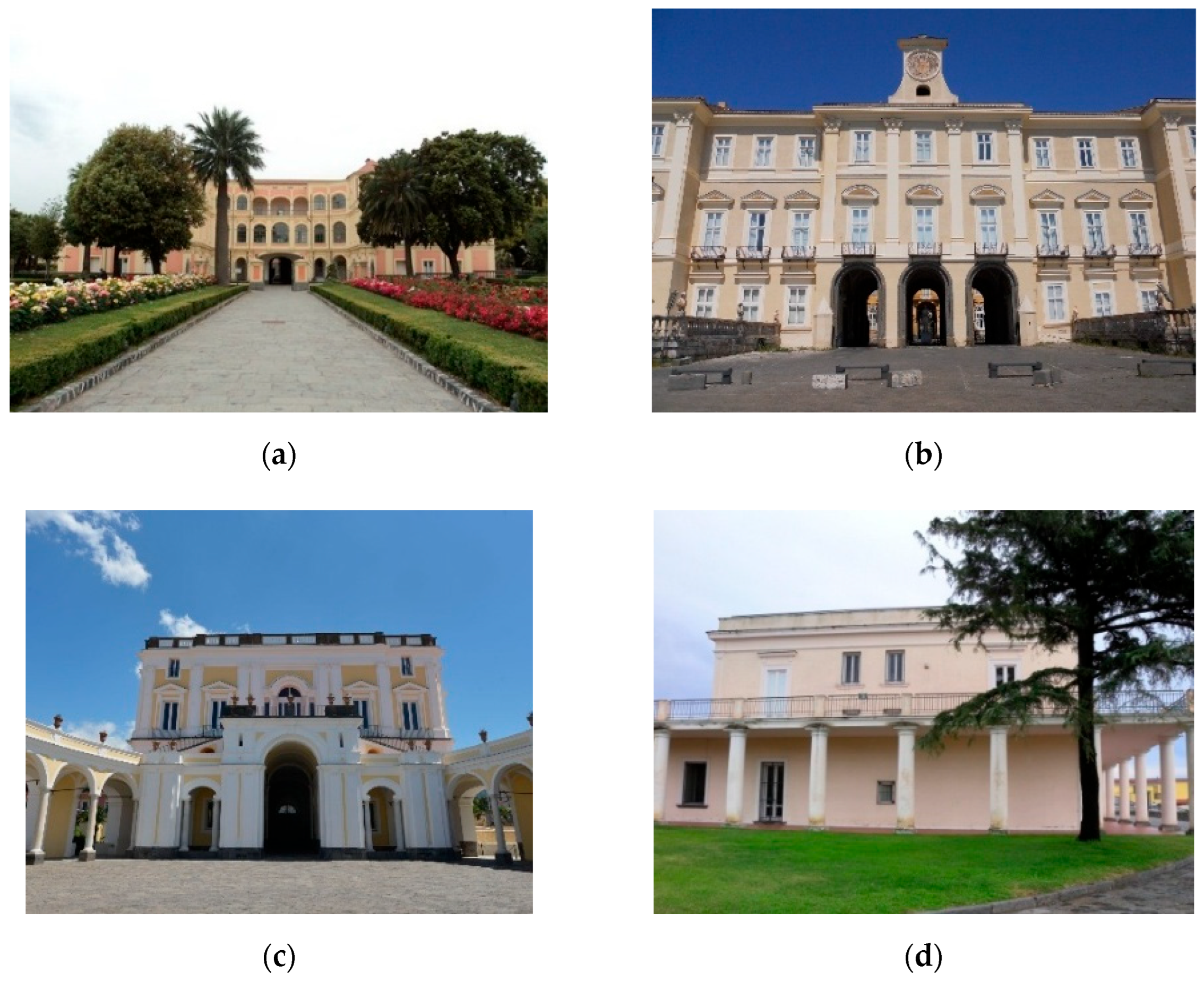
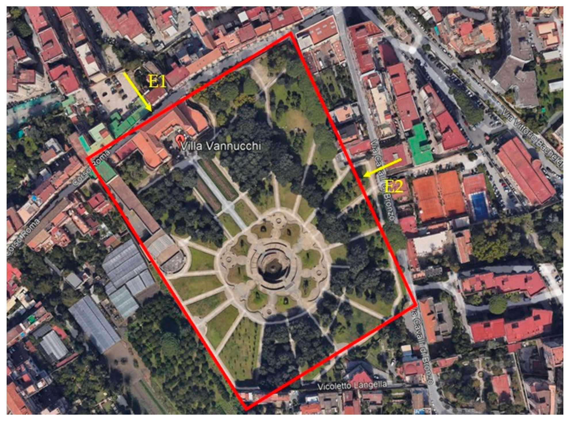
2. The Famous Villa Vannucchi in the Vesuvius Area

2.1. The Golden Mile

The remarkable Villa Vannucchi, the focus of the current study, is located in San Giorgio a Cremano, a city within the metropolitan area of Naples. The Villa is part of the broader context of the so-called “Golden Mile”, a term coined in the 20th century to describe a one-mile stretch of road extending from Naples to Torre del Greco. This route runs through various districts on the slopes of Mount Vesuvius and is characterized by the presence of numerous villas belonging to the Neapolitan nobility. A total of 122 palaces have been identified along the Golden Mile.
Among the most renowned are Villa Vannucchi, Villa Bruno, and Villa Pignatelli, all situated in San Giorgio a Cremano. Nearby, the Royal Palace of Portici, once the summer residence of the Bourbon dynasty, stands as a notable landmark. Other significant properties in the area include Villa Campolieto in Ercolano and Villa delle Ginestre in Torre del Greco, the latter famous as the last residence of the Italian poet Leopardi.
These villas share a Baroque architectural style, featuring impressive facades adorned with elaborate decorations, loggias, and terraces that offer panoramic views of the Gulf of Naples. They are often complemented by expansive gardens.
In the 19th century, with the decline of the Bourbon nobility, many of these villas were either abandoned or repurposed for different uses. This trend continued until 1971, when the Italian Parliament established the Vesuvian Villas Association to preserve and promote this significant architectural heritage [13].
The presence of these historic constructions represents a valuable opportunity for boosting tourism in the region. However, to fully realize this potential, it is essential to assess their seismic vulnerability and, where necessary, implement consolidation measures to ensure their safety.
Figure 1 shows external views of some of these villas located along the Golden Mile.

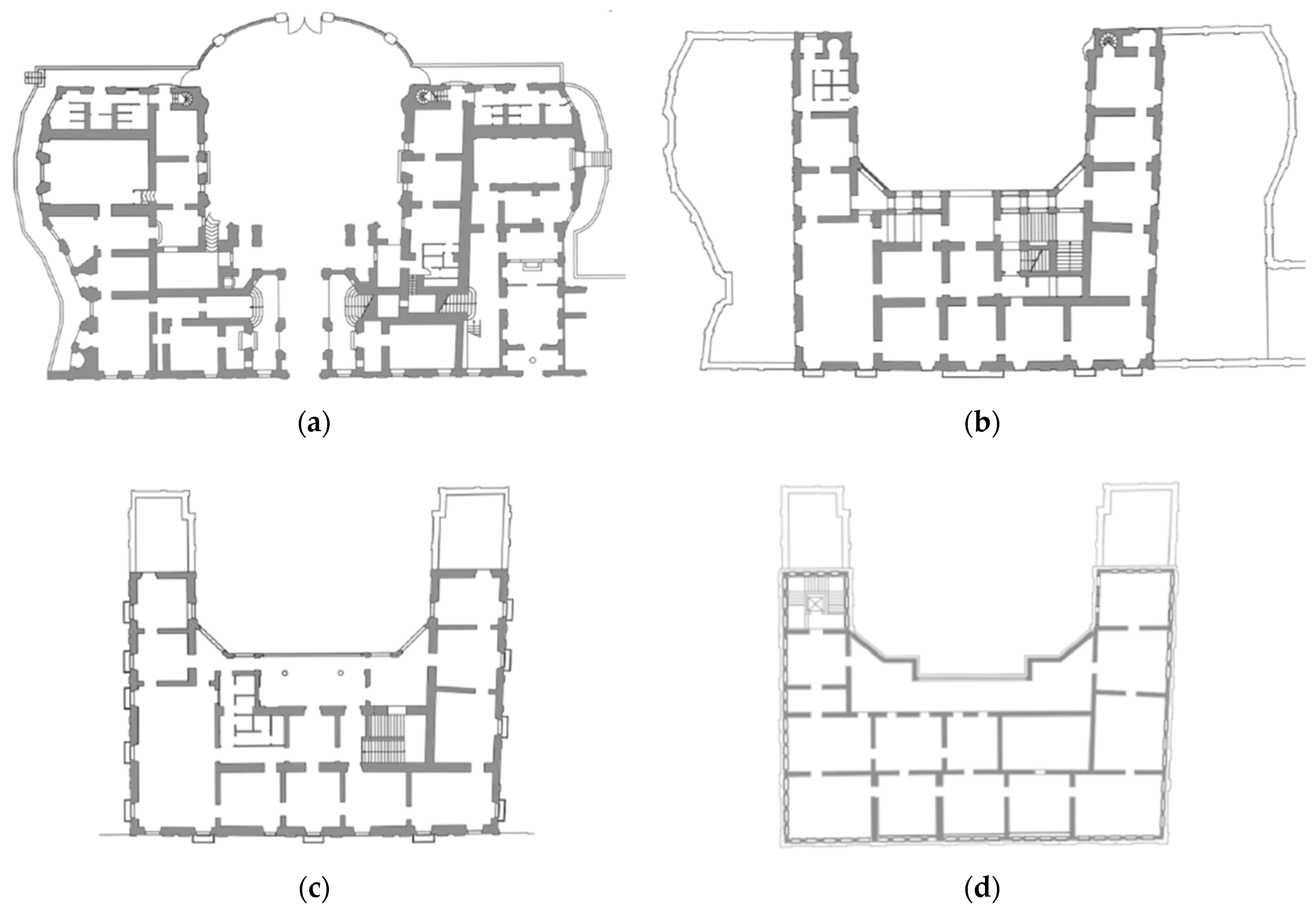
2.2. Historical Evolution and Main Structural Properties

Villa Vannucchi is located in the heart of the urban centre of San Giorgio a Cremano and features two entrances: one provides access to the Villa itself, while the other leads directly to the garden, designed as an extension of the interior spaces and as a typical “Italian garden” [14]. The placement and top view of the property are shown in Figure 2.
The residence is situated in a moderately seismic area and is also exposed to volcanic risk due to the proximity of Mount Vesuvius. Specifically, San Giorgio a Cremano falls within the red zone as defined by the National Civil Protection Plan for Volcanic Risk at Mount Vesuvius [15]. The red zone includes areas that could be directly affected by the most devastating effects of an eruption, where the only preventive measure is the evacuation of residents.
The Villa originated as a rural house in 1726. Several years later, it acquired the typical features of a noble residence with the addition of new spaces.
In 1755, the Prince of Caramanico purchased the property and commissioned an expansion, adding loggias and constructing a second level for residential purposes. A few years later, the prince acquired adjacent properties to further enlarge the villa. This expansion included the addition of two smaller, one-storey wings to accommodate a private chapel, stables, and an extended garden with a central fountain.
In the following centuries, the Villa underwent various modifications. However, it has retained much of its original configuration, making it a significant example of Vesuvian architecture.
In 1912, the property was sold to the Vannucchi family, and later, in 1998, the Villa was placed under the Superintendence’s protective bond. Since 2006, the complex has been owned by the Municipality of San Giorgio a Cremano.
The mansion has a “U-shaped” layout, with the central body consisting of three levels and the two lateral bodies comprising a single floor. The vertical walls are made of yellow tuff masonry, a typical material of the region, bonded with mortar. Wall thickness ranges between 60 and 80 centimetres. The ground floor rooms are covered with masonry vaults of varying geometries, while the upper levels feature intermediate floors made of chestnut timber beams, another traditional material used in the region for its durability and resistance, with a single layer of planks. The roof, also constructed with chestnut timber beams and tiles, has a double-pitched configuration.
Figure 3 illustrates the three-storey layout of the construction.
The historic Villa Vannucchi is located on a fine-grained soil with low consistency. The site is characterized by a peak ground acceleration (PGA) of 0.16 g.
Due to lack of maintenance and the effects of the 1980 Irpinia earthquake, the villa exhibited various forms of damage over time. The main damage observed included cracks near the openings facing the inner courtyard and around the arched ones inside the building. Additionally, some lesions formed on the vaulted ceilings at the ground floor, while localized crushing phenomena affected the masonry at the ground level.

3. Vulnerability Evaluation to Seismic Events

After gaining an understanding of the key historical and architectural features, essential for achieving a comprehensive knowledge as prescribed by the Italian Guidelines for Cultural Heritage, which is the normative reference for the entire project, the structural performance of the building was assessed in three progressively detailed steps.
In the first phase, conducted using Evaluation Level 1 (EL1), a qualitative analysis was carried out, obtaining two indicators of the building’s structural health.
Subsequently, through calculation software and the development of a three-dimensional model, both local and global mechanisms were investigated by means of EL2 and EL3.
The results from all three levels helped in identifying a consolidation plan by selecting the most appropriate interventions in order to safeguard the historical and architectural authenticity of Villa Vannucchi.

3.1. A Qualitative and Simplified Approach: Evaluation Level 1 of IGCH

The study of the seismic vulnerability of Villa Vannucchi began with Evaluation Level 1, which involves the use of simplified mechanical models and limited geometrical and structural data (e.g., the absence of in situ tests) [16,17].
This level calculates two key parameters, namely the acceleration factor and the seismic safety index.
The acceleration factor is defined as the ratio between the rigid ground acceleration corresponding to the life safety limit state return period (SLV) and the one associated with the reference return period:
f a , SLV   = a S L V a g , S L V
The second index is derived from the ratio between return period leading to the life safety limit state and the corresponding return period, as displayed in Equation (2):
I SS = T S L V T R , S L V
This first evaluation level provides an estimation of the seismic risk of cultural heritage on a territorial scale, enabling the establishment of a priority list for consolidation operations.
EL1 offers various simplified mechanical models tailored to different types of historical and monumental structures (Churches and Ecclesiastical Buildings, Palaces and Historic Residences, Bell Towers and Tall Masonry Structures).
In this case, the model titled “Palaces, villas and other structures with spine walls and intermediate floors” was adopted due to its specific applicability to villas and historic mansions.
In order to determine the two indices introduced above, it is first necessary to calculate the return period, as outlined in Equation (3):
T SLV = T 1   ·   10 log a g log a 1 log a 2 a 1 · log T 2 T 1 1
In the calculation of the return period TSLV, T1 and T2 represent the return periods for which seismic hazard is provided, within which TSLV is included, while a1 and a2 are the corresponding peak ground acceleration values on rigid soil.
Then, the acceleration corresponding to the Life Safety Limit State is calculated using one of the two expressions defined in Equation (4):
a SLV : S e , SLV ( T 1 ) S · F 0 if T B T 1 < T C S e , SLV ( T 1 ) S · F 0 · T 1 T C if T C T 1 < T D
In the previous expressions:
  • T1 is the fundamental period of vibration of the structure. It is calculated using the following relationship (Equation (5)):
T 1 = C 1 · H 3 4
The period is given by the product of a constant parameter C1, assumed in this case to be 0.05 for masonry structures, and H, which corresponds to the maximum height of the building, equal to 19.50 m.
  • TB, TC, and TD are the characteristic periods of the response spectrum;
  • F0 is the maximum value of the amplification factor of the horizontal acceleration spectrum;
  • S is a factor derived from the stratigraphic category coefficient SS multiplied by the coefficient accounting for the site’s topography ST;
  • Se,SLV is the collapse acceleration value of the elastic response spectrum, obtained as follows:
S e , SLV   = q · F SLV e · M
where:
  • FSLV is the building shear resistance;
  • q is the behaviour factor. It ranges between 3.0 and 3.6 for building regular in elevation and having at least a number of levels equal or greater than two [11,12]. For the current case study, a behaviour factor q equal to 3 is used;
  • M represents the total seismic mass;
  • e* is the participating mass fraction linked to the first vibration mode.
Once the shear resistance is calculated for the main directions and all levels of the construction, the lowest value among them must be considered for the verification process. The simplified mechanical model assumes that collapse occurs in each direction when the average shear reaches a specific masonry shear resistance. This resistance can be calculated using the formulas provided by Equation (7):
F SLV , xi = μ xi   ·   ξ xi   ·   ζ x ·   A xi · τ di β xi ·   κ i F SLV , yi = μ yi   ·   ξ yi   ·   ζ y ·   A yi · τ di β yi ·   κ i
where:
  • Axi and Ayi represent the shear resistant areas of the i-th floor walls located in the x- and y-directions, respectively;
  • τdi is the design value of the masonry piers shear strength at the i-th floor, defined as follows:
τ di   = τ 0 d 1 + σ 0 i 15 τ 0 d
where:
  • τ0d is the design value of the shear strength of masonry evaluated taking into account the confidence factor Fc, herein assumed as equal to 1.35;
  • σ0i is the average normal stress on the walls resistant area at the i-th floor.
  • ki is the ratio between the resultant of the seismic forces at the i-th floor and the total seismic force;
  • βxi and βyi are the planimetric irregularity coefficients of the i-th floor considering the eccentricity value between the centroid and stiffness centre. In this case, these coefficients assume the maximum value of 1.25;
  • μxi and μyi are coefficients which consider the stiffness and resistance homogeneity of masonry walls, which can be easily calculated by means of Equation (9):
μ xi =   1 0.2   N mxi · j A xi , j 2 A xi 2     1 0.8       μ yi =   1 0.2   N myi · j A yi , j 2 A yi 2     1 0.8
In the above formula, Nmxi and Nmyi represent the number of masonry piers in x- and y-directions, respectively, while Axi,j and Ayi,j are the areas of the generic piers in x and y directions, respectively.
  • ξxi and ξyi are coefficients connected to the main type of collapse mechanism expected in the masonry walls at the i-th floor. They assume a value equal to 1 if the collapse occurs for shear; otherwise, a value of 0.8 is used in case of failure under compression-bending moment. In the current case, a value of 1 is used for these coefficients;
  • ζx and ζy are coefficients associated with the wall spandrel resistance in the x- and y- directions, respectively. They are equal to 1 in the case of resistant spandrels, or they can assume a value of 0.8 for weak spandrels. Herein, these coefficients assume a value of 1.
Once these parameters are defined, the building’s shear strength is calculated in both directions for each level of the construction. Subsequently, the corresponding acceleration values are determined.
To determine the acceleration, the structure’s vibration period is computed according to the guidelines provided in the Italian standard [11,12]. This period is found to be equal to 0.44 s, which falls within the range between TB and TC. Therefore, the collapse acceleration on rigid ground can be calculated with the first expression between the two proposed in the guidelines (see Equation (4)), with a lower value of shear strength, which corresponds to the ground level value along y-direction.
Table 1 summarizes all the assumed values for the aforementioned coefficients.
The last step of the EL1 is the calculation of both the acceleration factor and the seismic safety index. The results of the two parameters are presented in Table 2 and Table 3 for each direction and at each level of the construction.
Since both indices are significantly lower than 1, the building exhibits high seismic vulnerability. Specifically, in both cases, the y-direction appears to be the weakest one. This may be due to the lower number of masonry piers in this direction compared with the other one.

3.2. Evaluation Levels 2 and 3

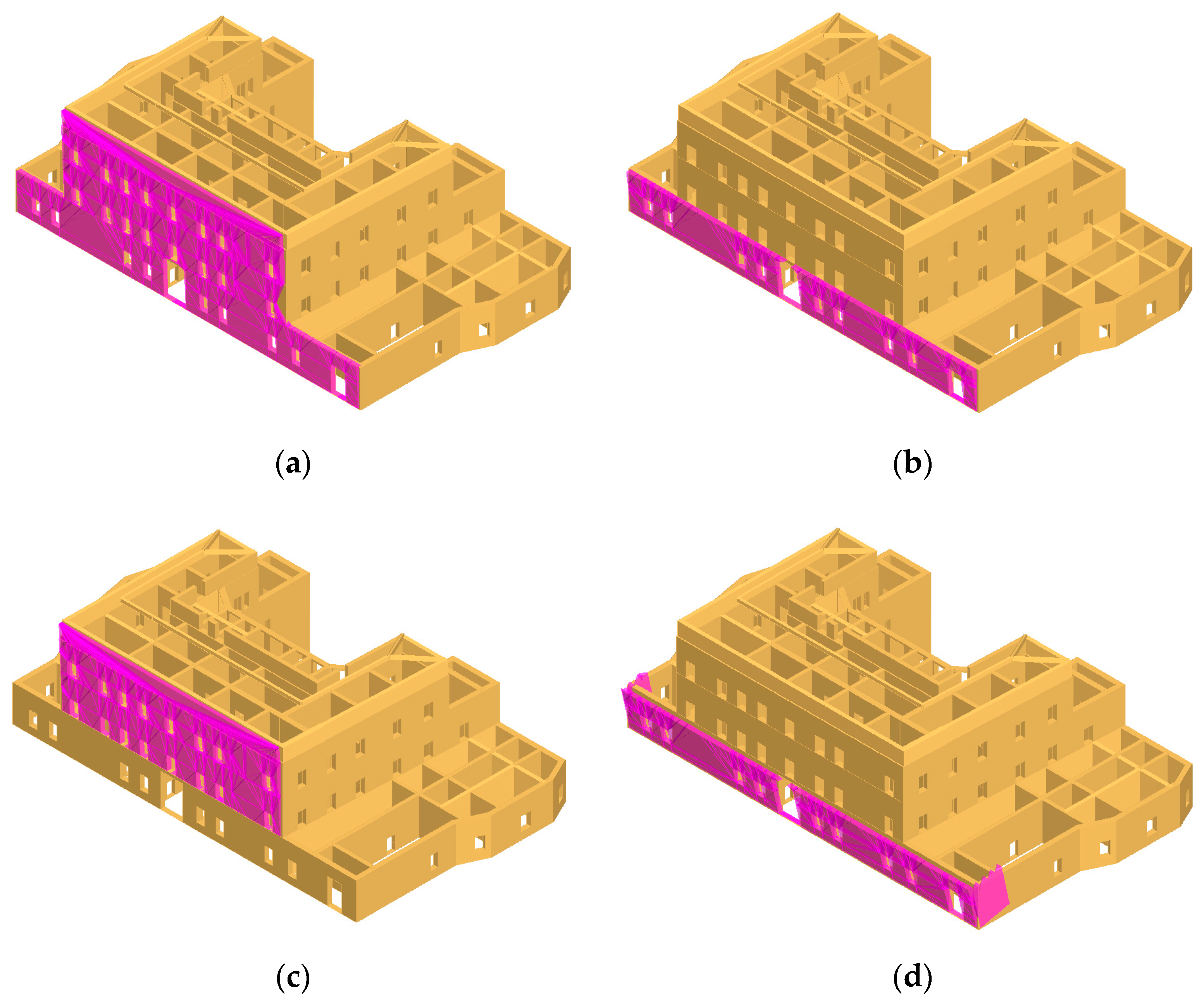
3.2.1. Examination of Local Collapse Mechanisms

In order to evaluate both the local and global mechanisms affecting the construction, EL2 and EL3 were carried out, respectively.
EL2 focuses on assessing first-mode mechanisms, also known as local collapse mechanisms, which involve structurally independent parts of the building.
Conversely, the third and final evaluation level (EL3) enables an assessment of the overall response of the entire structure.
Both analyses are conducted by defining a model using the calculation software 3Muri, developed by the STA.DATA company (Turin, Italy). The program is widely used as it allows for both linear and non-linear analyses of masonry and reinforced concrete structures with different intended uses [18,19,20,21].
The software adopts a frame by macro-element (FME) approach, which identifies three macro-elements for each masonry panel: masonry piers and spandrels, where deformation and damage are concentrated, and rigid nodes, which are assumed to have infinitely rigid behaviour. This method is derived from the observation of real damage in structures affected by earthquakes.
The model is developed using the lowest level of knowledge (KL1) as defined by the Italian Technical Standard, with a corresponding confidence factor (Fc) of 1.35. Consequently, average values for elastic moduli and minimum ones for resistances are adopted.
The classification of the existing masonry types, based on Table C8.5.I, includes, in addition to tuff masonry, random rubble masonry, coursed rubble masonry with roughly hewn stones, split stone masonry with good texture, masonry with squared stone blocks, and masonry with solid bricks bonded with lime mortar.
The mechanical parameters for tuff masonry are summarized in Table 4.
Figure 4 depicts the three-dimensional and the meshed models of Villa Vannucchi.
The linear kinematic analysis method has been used for the investigation of local collapse mechanisms. This approach assumes that the masonry has zero tensile strength, but exhibits infinite compressive strength. The absence of tensile strength leads to the failure of the masonry panel due to the loss of equilibrium. For the purpose of evaluating the mechanisms, a portion of the masonry is transformed into a kinematic chain by identifying rigid bodies capable of rotating or translating relative to one another [22,23,24].
For life safety limit state verifications, a simplified check is performed. This condition is considered satisfied if the spectral seismic acceleration that activates the kinematics, a 0 , is greater than the peak ground seismic acceleration, a0,min:
a 0   a 0 , m i n
where:
a 0 = α 0 · g e · F C · q
in which:
  • α 0 is the multiplier of the seismic action inducing the collapse, determined using the principle of virtual works;
  • g is the gravity acceleration;
  • e is the participating mass fraction associated with the first vibration mode;
  • Fc is the confidence factor;
  • q is the behaviour factor, equal to 2.
a 0 , m i n = a g · S q
where:
  • ag is the peak ground acceleration, a function of the probability of exceeding the chosen limit state;
  • S is the coefficient which accounts for the foundation soil.
Equation (10), used for the check and corresponding to the Equation C8A.4.9 of the Italian Technical Code [11,12], is applicable only to masonry portions that are anchored to the ground.
In contrast, for masonry walls with hinge at a specific height, the following expression (13), which correspond to Equation C8A.4.10 of the Italian Ministerial Circular n.7/2019 [9], is adopted:
a 0 , m i n = S e ( T 1 ) · ψ ( Z ) · Υ q
where:
  • S e ( T 1 ) is the ordinate of the elastic spectrum, which depends on the first vibration period T1;
  • ψ is the first vibration mode in the considered direction;
  • γ is the modal participation coefficient. In the absence of more accurate assessments, this parameter can be assumed as 3N/(2N + 1) where N is the number of floors of the building;
  • q is the behaviour factor.
For Villa Vannucchi, the historic mansion under evaluation, the local mechanisms analysed are listed and shortly described below:
  • Global or partial overturning: this phenomenon occurs when entire facades or sections of them rotate rigidly around horizontal axes;
  • Composite overturning: this mechanism behaves as the rigid rotation of entire facades or sections of walls around mainly horizontal axes, accompanied by the dragging of parts of the masonry structure belonging to the bracing walls.
Both partial and global overturning mechanisms were evaluated to assess the potential failure modes of the structure under lateral forces. These mechanisms provide insight into how different parts of the building may respond to stresses such as seismic or wind loads. In particular, a partial overturning mechanism focused on the ground floor was examined to determine whether the thrust from the masonry vaults is effectively absorbed or leads to localized failure.
Conversely, the composite overturning mechanism was analysed to assess the bonding between perimeter walls. This evaluation aimed to understand how the interconnection of walls might influence the overall stability of the structure and either mitigate or contribute to collapse.
The mechanisms mentioned above have been assessed for the perimeter walls of the examined building, as illustrated in Figure 5.
Table 5 shows the results for all the perimeter walls that, in almost all cases, are not satisfied.
Table 6 contains the values of the main values used for the evaluation of the four local collapse mechanisms referring to the main façade.

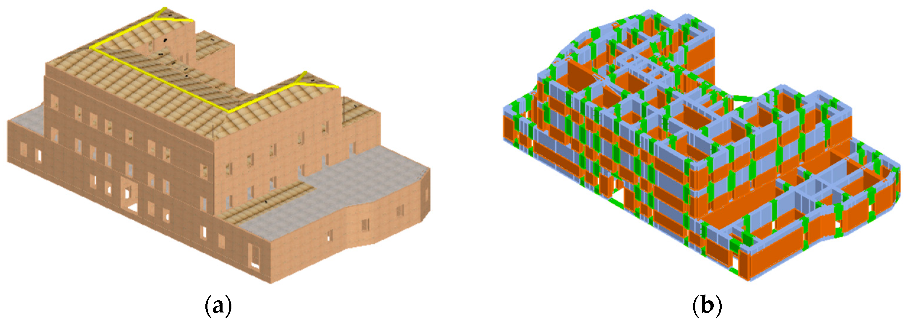
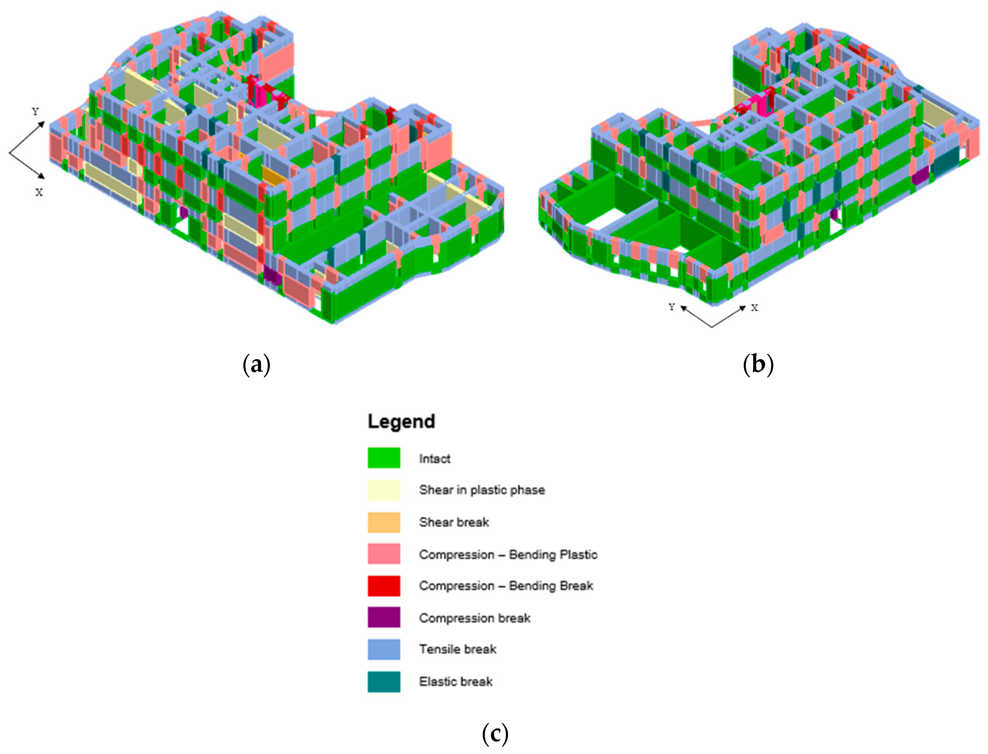
3.2.2. Global Behaviour

In the final stage, the global performance of the structure via the last evaluation level (EL3) is assessed.
In particular, the software allows for the execution of static non–linear analyses monitoring the displacement of a top control node. Following the provisions given by the Italian Technical Code, analyses were carried out taking into account two horizontal forces distributions: the first distribution corresponds to static forces, while the second one is derived from a uniform distribution of acceleration across the height of the building.
Table 7 summarizes the results of the two most critical analyses in terms of the α coefficient, which is defined by the ratio of the peak ground acceleration capacity over the demand one (PGAC/PGAD).
Figure 6 illustrates damage affecting the construction in the two main analysis directions. For the portion of masonry placed above the openings, compression–bending (along X-direction) and elastic (in both directions) failures are the most widespread mechanisms. On the contrary, shear and compression–bending collapses are the governing failures for masonry piers in the longitudinal direction.

4. Strengthening Plan

Since both EL1 and EL3 highlight that the y-direction is the weakest, with very low coefficient values, several structural interventions are proposed to reduce the seismic vulnerability of the Villa. All the techniques were carefully chosen based on compatible materials to ensure long-term durability, while also preserving the historical integrity of the existing structure.

4.1. Interventions on Masonry Piers and Floors

Several interventions are planned to enhance the mechanical strength and ductility of the masonry panels, aiming to improve the overall structural performance of the building and reduce the risk of collapse [25,26]. These interventions include the scuci-cuci technique, consolidation injections, and repointing of the joints. A brief description of each method is provided below.

4.1.1. Scuci-Cuci Technique

This traditional “scuci-cuci” technique is one of the most common and widely used methods for repairing masonry panels. The solution involves replacing degraded stones with new ones made of the same material by restoring the continuity of the wall along the crack lines.
The process begins with stabilizing the wall to both prevent further damage and ensure safety during the repair work. If plaster is still present, it is carefully removed to expose the masonry. The damaged blocks, along with neighbouring stones around the cracks, are then removed. The exposed area is cleaned using high-pressure water to eliminate dust and debris. Finally, new stones are inserted with a slightly expansive or non-shrinking grout and the masonry panel is reconstructed from base to top, ensuring proper alignment and structural integrity.
This procedure is recommended for all vertical panels affected by crushing or cracks.

4.1.2. Consolidating Injections

Another strengthening intervention involves the injection of consolidating mixtures in order to enhance the mechanical properties of the masonry, improving the wall’s load-bearing capacity by increasing cohesion between the tuff blocks.
The process can be summarized in the following phases:
  • Identification of injection points: A grid of holes, usually arranged in square or triangular patterns, spaced approximately 30–50 cm apart, is created to guide the process;
  • Removal of any existing plaster;
  • Drilling of holes: Holes with a 30 mm diameter are drilled following the pattern created in the previous phase, ensuring an even distribution for the injection;
  • Installation of injection ports: Special nozzles are inserted into the holes to facilitate the controlled injection of the binding mixture;
  • Cleaning of holes: The holes are washed with high-pressure water to remove dust and debris for an optimal penetration of the binding agent;
  • Gravity injection of the mixture: A fluid binding mixture is injected gradually from the upper holes to the lower ones, allowing it to fill voids and consolidate the masonry;
  • Sealing of holes: Once the injection process is complete, the holes are carefully sealed to restore the surface and ensure a cohesive finish.
It is important to note that injections are typically performed from the bottom up, starting from the base to prevent overloading from above. The pressure of the mixture’s inlet should be carefully monitored to avoid excessive pressure, especially near weak points, where simple pouring may be preferred.
Additionally, the choice of mixture is crucial. Cement-based mortars are not recommended, as they can produce salts that lead to efflorescence on the surface. Instead, lime grout is used as the binding agent to ensure proper chemical and physical compatibility with the masonry.

4.1.3. Re-Styling of the Joints

A further operation to enhance the strength of the masonry panels involves re-styling the joints with mortar that has a similar chemical composition to the existing one. This ensures compatibility and prevents potential issues with unsuccessful repairs.
In the end, in order to avoid overturning phenomena of perimeter walls, the design of metal ties having 18 mm diameter is hypothesized.
Several consolidation measures are also planned for the horizontal floors, particularly for those made of timber beams. These include replacing the beam heads and installing a second plank to reduce floor deformation.
The final intervention aimed at stiffening the floor involves laying a second plank. After securing the area beneath the ceiling to be consolidated for safety reasons, any traces of existing floor and screed are removed. This exposes the first layer of plank onto which the second one will be installed. It is placed either orthogonally or at a 45° angle to the existing plank, with the 45° arrangement being selected in this case. The new plank is then bonded to the original one using an epoxy adhesive. Once these steps are completed, the floor is finished with a screed, followed by the installation of new flooring. An important consideration is ensuring a proper connection between the new planking and the masonry walls.
As for the vaulted ceilings, the cracks are filled using compatible mixtures where present.

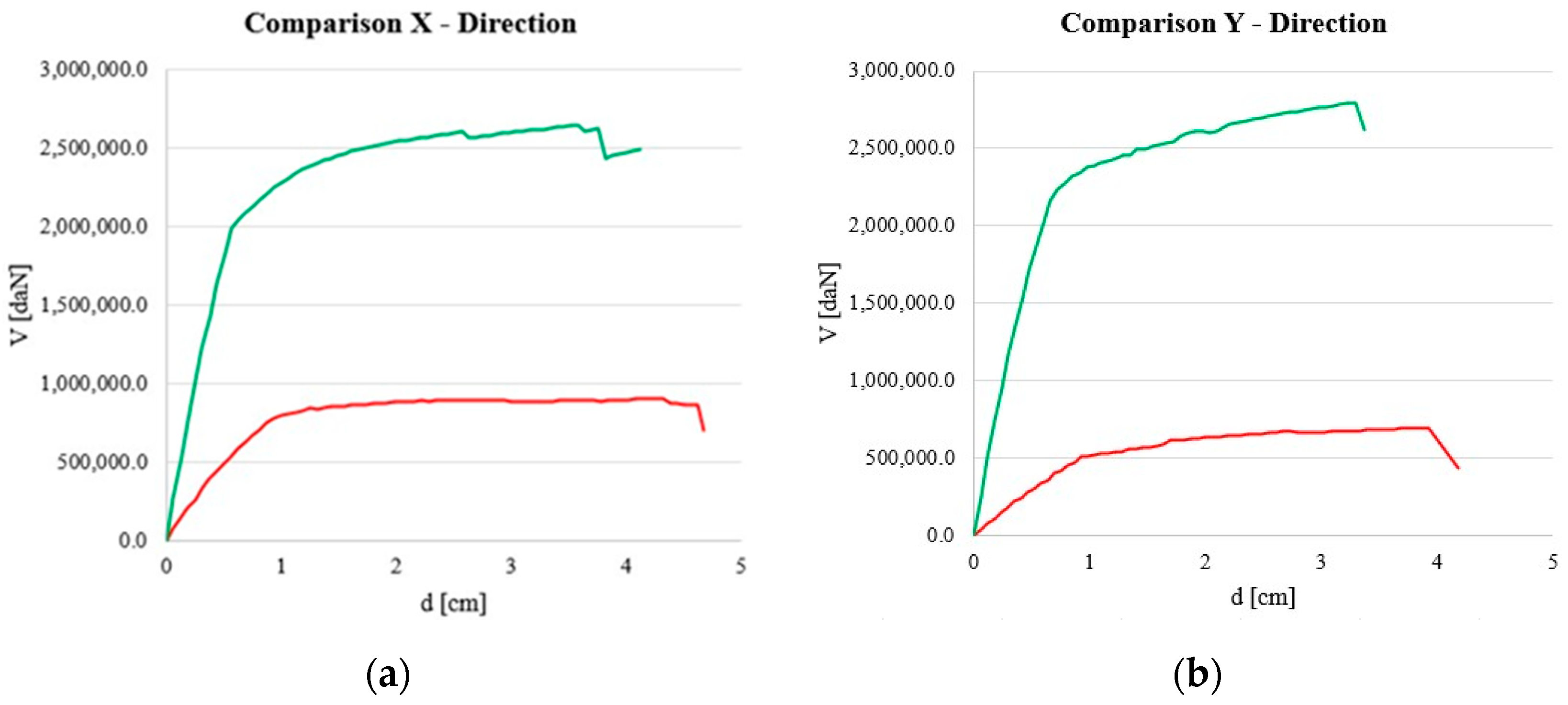
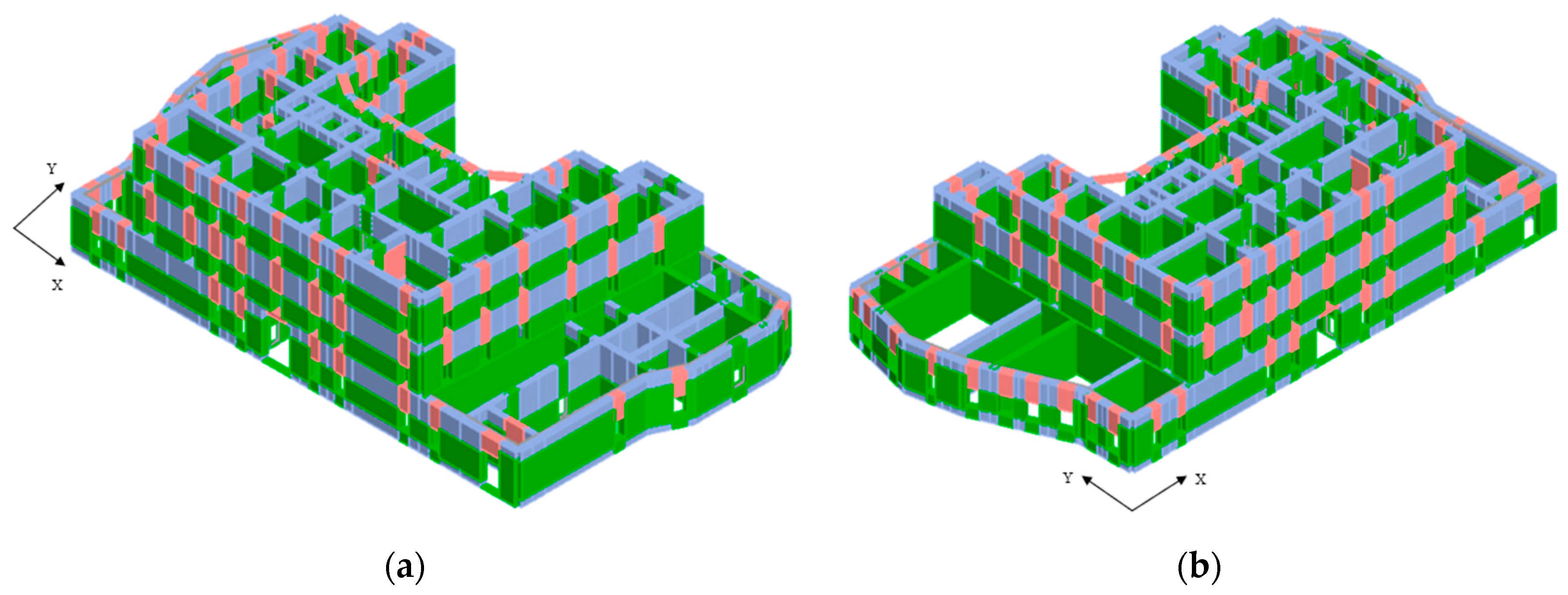
4.2. Performance of the Retrofitted Structure and Comparison with the As-Built State

Afterwards, all the hypothesized operations are inserted into the software model and the pushover analyses are repeated again.
To account for the various interventions planned in the targeted consolidation plan illustrated in the previous section, and in accordance with the instructions contained in Chapter 8 of the current Italian technical code NTC 2018 regarding the existing constructions, appropriate improvement coefficients have been selected [12]. Specifically, Table C8.5.II outlines the use of specific factors that vary depending on the type of masonry and the planned intervention.
For the case study, a coefficient of 1.4 has been assumed to account for consolidating injections. This coefficient applies to both strength parameters and elastic moduli (E and G). Additionally, a second timber boarding layer is planned for installation on the floors in the areas subject to this intervention. When properly connected to the masonry walls, this additional layer enhances stiffness, thereby improving resistance to seismic forces.
To account for the improvement in mortar performance resulting from consolidation injections, an enhancement coefficient of 1.5 was applied.
According to the Italian Technical Standards Circular, when multiple strengthening interventions are implemented on masonry, their respective improvement coefficients must be combined multiplicatively. In this case, the product of the applied coefficients exceeded 2. However, given that the standards specify a maximum allowable value of 2 for irregular tuff stone masonry, this upper limit was adopted.
The main mechanical parameters assumed for the retrofitted masonry panels—adjusted based on the improvement coefficient—are summarized in Table 8.
A second 3 cm thick wooden floor layer was then added, ensuring strong adhesion to the existing floor through nailing, and securely connected to the perimeter walls. The properties of the chestnut wood used—selected to meet compatibility criteria—are detailed in Table 9.
Finally, steel S275 chains were also introduced into the model, with local checks being carried out in a subsequent phase.
The α coefficients for the two most critical analyses, depicted in Table 10, evidence an increasing greater than 0.1 as required by the Italian Technical Code, thereby ensuring a seismic upgrading of the structure.
Figure 7 illustrates a comparison between the capacity curves before and after the proposed consolidation plan. These curves demonstrate a significant improvement following the retrofitting operations, with a substantial increase in both resistance and stiffness.
Figure 8 displays the damage mechanisms in the two analysis directions after the implementation of consolidation interventions. These operations significantly reduce shear failures affecting the masonry piers and considerably improve the overall behaviour of the structure.
Table 11 presents the results of the modal analysis for both models.
Consolidation interventions have increased the structure’s stiffness, as indicated by reduced vibration periods. The asymmetry between the X and Y directions remains due to the structure’s layout. Overall, consolidation enhances rigidity and potentially improves seismic resistance.
The presence of the metal tie rods, designed and verified using the 3Muri software, enables them to avoid overturning mechanisms. The chains, placed in correspondence of each room and every 5/6 m, are verified by performing the masonry punching verification, anchor penetration verification and chain yield strength verification.
Additionally, the analysis of the first mode mechanisms was repeated, confirming the effectiveness of the used metal chains.
Notably, the overturning phenomena of the perimeter walls were negligible. The analysis results are presented in Table 12.
Table 13 reports the results of the kinematic analysis carried out for the main façade after the consolidation plan. The overturning phenomena, both of global and partial types, were disregarded due to the presence of metal chains.

5. Conclusions

Villa Vannucchi, located in San Giorgio a Cremano near Naples, is a remarkable example of 18th century Vesuvian architecture. Originally built as a rural house in 1726, it was later expanded into a noble residence. With its U-shaped layout, yellow tuff masonry walls, and a combination of masonry vaults and timber floors, the villa embodies the architectural style of the “Golden Mile”, a historic route known for its baroque villas and scenic views of the Gulf of Naples. Despite its cultural and historical significance, the villa exhibited serious seismic vulnerabilities due to its age, unreinforced masonry construction, and location in a moderately seismic and volcanic region.
The seismic assessment of Villa Vannucchi followed a three-phase methodology based on the Italian Guidelines for Cultural Heritage. Structural analyses revealed critical weaknesses, particularly in the y-direction, due to the insufficient number of masonry piers and poor connections between structural elements. Preliminary evaluations (EL1) indicated low safety indices, while more detailed assessments (EL2 and EL3) highlighted high susceptibility to both local and global collapse mechanisms.
To address these structural deficiencies, a tailored consolidation plan was developed. Key masonry interventions included the “scuci e cuci” technique for replacing damaged stones, injection-based consolidation to enhance cohesion, and joint restoration using compatible mortars. Floors were reinforced by replacing deteriorated beam heads and adding a secondary plank layer bonded with epoxy resin to increase stiffness and reduce deformation. Additionally, metal ties were installed to prevent the overturning of perimeter walls.
Post-retrofitting analyses demonstrated significant improvements. The αSLV coefficients increased by 77% in the x-direction and 88% in the y-direction, surpassing the safety thresholds set by Italian technical standards. Capacity curves showed substantial gains in resistance and stiffness, confirming the effectiveness of the interventions. These results highlight a successful enhancement of the villa’s seismic performance while preserving its historical and architectural integrity.
By reducing seismic risk, this project ensures the long-term preservation of Villa Vannucchi as a cultural and historical landmark. The applied methods provide a replicable framework for restoring and safeguarding other heritage structures in seismically active regions facing similar challenges.

Author Contributions

Conceptualization, G.L. and A.F.; methodology, G.L. and A.F.; software, G.L.; validation, G.L. and A.F.; formal analysis, G.L.; investigation, G.L.; resources, A.F.; data curation, G.L. and A.F.; writing—original draft preparation, G.L.; writing—review and editing, A.F.; visualization, G.L. and A.F.; supervision, A.F.; project administration, A.F.; funding acquisition, A.F. All authors have read and agreed to the published version of the manuscript.

Funding

This research received no external funding.

Institutional Review Board Statement

Not applicable.

Informed Consent Statement

Not applicable.

Data Availability Statement

The data supporting the reported results can be obtained from the authors upon request.

Conflicts of Interest

The authors declare no conflicts of interest.

References

  1. Cardinali, V.; Ciuffreda, A.L.; Coli, M.; De Stefano, M.; Meli, F.; Tanganelli, M.; Trovatelli, F. An Oriented H-BIM Approach for the Seismic Assessment of Cultural Heritage Buildings: Palazzo Vecchio in Florence. Buildings 2023, 13, 913. [Google Scholar] [CrossRef]
  2. Chisari, C.; Zizi, M.; Lavino, A.; Freda, S.; De Matteis, G. Operational Modal Analysis and Safety Assessment of a Historical Masonry Bell Tower. Appl. Sci. 2024, 14, 10604. [Google Scholar] [CrossRef]
  3. Torelli, G.; D’Alaya, D.; Betti, M.; Bartoli, G. Analytical and numerical seismic assessment of heritage masonry towers. Bull. Earthq. Eng. 2020, 18, 969–1008. [Google Scholar] [CrossRef]
  4. Diaferio, M.; Foti, D.; Sabbà, M.F.; Lerna, M. A procedure for the seismic risk assessment of the cultural heritage. Bull. Earthq. Eng. 2021, 19, 1027–1050. [Google Scholar] [CrossRef]
  5. Longobardi, G.; Formisano, A. Seismic vulnerability assessment and consolidation techniques of ancient masonry buildings: The case study of a Neapolitan Masseria. Eng. Fail. Anal. 2022, 138, 106306. [Google Scholar] [CrossRef]
  6. Puncello, I.; Caprili, S. Seismic Assessment of Historical Masonry Buildings at Different Scale Levels: A Review. Appl. Sci. 2023, 13, 1941. [Google Scholar] [CrossRef]
  7. Diana, L.; Vaiano, G.; Formisano, A.; Scandolo, L.; Podestà, S.; Lestuzzi, P. The seismic vulnerability assessment of heritage buildings: A holistic methodology for masonry churches. Int. J. Archit. Herit. 2023, 18, 994–1022. [Google Scholar] [CrossRef]
  8. Lourenco, P.B. Assessment, diagnosis and strengthening of Outeiro Church, Portugal. Constr. Build. Mater. 2005, 19, 634–645. [Google Scholar] [CrossRef]
  9. Ceroni, F.; Pecce, M.; Sica, S.; Garofano, A. Assessment of seismic vulnerability of a historical masonry building. Buildings 2012, 2, 332–358. [Google Scholar] [CrossRef]
  10. Ministry for Cultural Heritage and Activities. Circular No. 26 of December 2, 2010: Guidelines for the Assessment and Reduction of Seismic Risk of Cultural Heritage—Alignment with the New Technical Standards for Construction; Ministry for Cultural Heritage and Activities: Rome, Italy, 2010. [Google Scholar]
  11. Ministry of Infrastructure and Transport. Technical Standards for Construction; Official Gazette (nr. 42 of 20/02/2018): Rome, Italy, 2018. (In Italian) [Google Scholar]
  12. Ministerial Circular n.7/2019 (M. C., 02/01/2019). Instructions for the Application of the “Upgrading of Technical Codes for Constructions” (M. D: 17/01/2018); Official Gazette of the Italian Republic: Rome, Italy, 2019. [Google Scholar]
  13. Fondazione Ville Vesuviane. Available online: https://www.villevesuviane.net/ (accessed on 9 January 2025).
  14. Nocca, F.; Angrisano, M. The Multidimensional Evaluation of Cultural Heritage Regeneration Projects: A Proposal for Integrating Level(s) Tool—The Case Study of Villa Vannucchi in San Giorgio a Cremano (Italy). Land 2022, 11, 1568. [Google Scholar] [CrossRef]
  15. Protezione Civile. Available online: https://www.protezionecivile.gov.it/it/approfondimento/aggiornamento-del-piano-nazionale-di-protezione-civile-il-vesuvio/ (accessed on 9 January 2025).
  16. Bartoli, G.; Betti, M.; Vignoli, A. A numerical study on seismic risk assessment of historic masonry towers: A case study in San Gimignano. Bull. Earthq. Eng. 2016, 14, 1475–1518. [Google Scholar] [CrossRef]
  17. Formisano, A.; Marzo, A. Simplified and refined methods for seismic vulnerability assessment and retrofitting of an Italian cultural heritage masonry building. Comput. Struct. 2017, 180, 13–26. [Google Scholar] [CrossRef]
  18. S.T.A. DATA. 3 Muri Program 14.2.0. Available online: http://www.stadata.com (accessed on 15 January 2025).
  19. Ademović, N.; Toholj, M.; Radonić, D.; Casarin, F.; Komesar, S.; Ugarković, K. Post-Earthquake Assessment and Strengthening of a Cultural-Heritage Residential Masonry Building after the 2020 Zagreb Earthquake. Buildings 2022, 12, 2024. [Google Scholar] [CrossRef]
  20. Valluzzi, M.R.; Sbrogiò, L.; Saretta, Y. Intervention Strategies for the Seismic Improvement of Masonry Buildings Based on FME Validation: The Case of a Terraced Building Struck by the 2016 Central Italy Earthquake. Buildings 2021, 11, 404. [Google Scholar] [CrossRef]
  21. Lamego, P.; Lourenço, P.B.; Sousa, M.L.; Marques, R. Seismic vulnerability and risk analysis of the old building stock at urban scale: Application to a neighbourhood in Lisbon. Bull. Earthq. Eng. 2017, 15, 2901–2937. [Google Scholar] [CrossRef]
  22. D’Ayala, D.; Speranza, E. Definition of Collapse Mechanisms and Seismic Vulnerability of Historic Masonry Buildings. Earthq. Spectra 2003, 19, 479–509. [Google Scholar] [CrossRef]
  23. Chiozzi, A.; Grillanda, N.; Milani, G.; Tralli, A. UB-ALMANAC: An adaptive limit analysis NURBS-based program for the automatic assessment of partial failure mechanisms in masonry churches. Eng. Fail. Anal. 2018, 85, 201–220. [Google Scholar] [CrossRef]
  24. Milani, G. Upper bound sequential linear programming mesh adaptation scheme for collapse analysis of masonry vaults. Adv. Eng. Softw. 2015, 79, 91–110. [Google Scholar] [CrossRef]
  25. De Vita, M.; Mannella, A.; Sabino, A.; Marchetti, A. Seismic Retrofit Measures for Masonry Walls of Historical Buildings, from an Energy Saving Perspective. Sustainability 2018, 10, 984. [Google Scholar] [CrossRef]
  26. Binda, L.; Modena, C.; Baronio, G.; Abbaneo, S. Repair and investigation techniques for stone masonry walls. Constr. Build. Mater. 1997, 11, 133–142. [Google Scholar] [CrossRef]
Figure 1. Some important villas placed along the Golden Mile: (a) Villa Vannucchi (object of the current work); (b) Royal Palace of Portici; (c) Villa Campolieto; (d) Villa delle Ginestre.
Heritage 08 00143 g001
Figure 2. Top view of Villa Vannucchi with the identification of the two entrances: E1, main entrance to the Villa, and E2, entrance to the garden (Source: Google Earth, 2024).
Heritage 08 00143 g002
Figure 3. The storeys of the historic construction: (a) ground floor; (b) first level; (c) second level; (d) attic level.
Heritage 08 00143 g003
Figure 4. (a) Three-dimensional model and (b) meshed structure of Villa Vannucchi with masonry piers in brown, spandrels in green, and rigid nodes in light blue.
Heritage 08 00143 g004
Figure 5. Local collapse mechanisms analysed: (a) simple overturning; (b) partial overturning with ground constraint; (c) partial overturning with hinge at a certain altitude; (d) composite overturning.
Heritage 08 00143 g005
Figure 6. Damage on the three-dimensional model: (a) analysis nr. 15; (b) analysis nr. 23; (c) legend of mechanisms.
Heritage 08 00143 g006
Figure 7. Comparison of capacity curves along the (a) x–direction and (b) y-direction (red: before the consolidation; green: after the consolidation).
Heritage 08 00143 g007
Figure 8. Damage on the three-dimensional model after the strengthening plan: (a) analysis nr. 15; (b) analysis nr. 23.
Heritage 08 00143 g008
Table 1. List of the coefficients used for calculation of the shear resistances.
Ground Floor
τdiτ0dμxμyζxζyξxξyβxβyk
[kN/m2][kN/m2]---------
39.120.740.8260.87811111.251.251
First Floor
τdiτ0dμxμyζxζyξxξyβxβyk
[kN/m2][kN/m2]---------
41.320.740.8660.89411111.251.250.9
Second Floor
τdiτ0dμxμyζxζyξxξyβxβyk
[kN/m2][kN/m2]---------
42.120.740.8530.83411111.251.250.7
Attic
τdiτ0dμxμyζxζyξxξyβxβyk
[kN/m2][kN/m2]---------
51.020.740.8450.83811111.251.250.4
Table 2. Results of the acceleration factor fa for the two main directions at all levels of the structure.
fa,SLVGround FloorFirst FloorSecond FloorAttic
x-direction0.540.300.290.39
y-direction0.380.370.260.33
Table 3. Results of safety seismic index ISS for the two main directions at all levels of the structure.
ISSGround FloorFirst FloorSecond FloorAttic
x-direction0.380.310.300.34
y-direction0.340.340.290.32
Table 4. Mechanical parameters assumed in the FME model.
Tensile Strength fmYoung Modulus
E
Shear Modulus
G
Specific Weight
w
Shear Strength
τ
(N/mm2)(N/mm2)(N/mm2)(kN/m3)(N/cm2)
1.401080360162.8
Table 5. Results of EL2.
Local MechanismsNo. of Walls AnalysedNo. of Positive CheckNo. of Negative Check
Simple overturning808
Partial overturning–ground hinge808
Partial overturning808
Composite overturning954
Table 6. Results of the verifications conducted on the main façade.
Local Mechanisms α 0 e*qγψ a 0 a 0 , m i n
Simple OT.0.0430.732--0.86443.2062
Partial OT (Ground H.)0.1210.782--2.27443.2062
Partial OT0.0600.7921.290.43951.10193.0052
Composite OT0.2110.782--3.88453.2062
Table 7. Results of the two most critical pushover analyses.
NrEarthquake DirectionSeismic LoadEccentricity (cm)αSLV
15−XUniform157.230.282
23−YStatic forces296.520.125
Table 8. Mechanical parameters assumed in the FME retrofitted model.
Tensile Strength fmYoung Modulus
E
Shear Modulus
G
Specific Weight
w
Shear Strength
τ
(N/mm2)(N/mm2)(N/mm2)(kN/m3)(N/cm2)
2.802160720165.6
Table 9. Mechanical properties of the chestnut wood used for the second plank.
Young’s Modulus EShear Modulus GSpecific Weight wAverage Compr. Strength fwmCharacteristic Compr. Strength fkmKmodγM
(N/mm2)(N/mm2)(kN/m3)(N/mm2)(N/mm2)(-)(-)
11,0009500639280.61.45
Table 10. Comparison of the results before and after the consolidation plan.
NrEarthquake DirectionSeismic
Load
Eccentricity (cm)Before
αSLV
After αSLVΔ = After αSLV/Before αSLV (%)
15−XUniform157.230.2821.236438%
23−YStatic forces296.520.1251.062850%
Table 11. Mode shapes of the building before and after consolidation interventions.
I ModeII Mode
PeriodMass RatioPeriodMass Ratio
Before consolidation0.4395 s56.84% (X)0.4117 s67.91% (Y)
After consolidation0.3951 s72.32% (X)0.3822 s71.55% (Y)
Table 12. Results of EL2 after the consolidation plan.
Local MechanismsNo. of Walls AnalysedNo. of Positive CheckNo. of Negative Check
Simple overturning880
Partial overturning–ground hinge880
Partial overturning880
Composite overturning990
Table 13. Results of the verifications conducted for the main façade after the consolidation plan.
Local Mechanisms α 0 e*qγψ a 0 a 0 , m i n
Simple OT.0.2630.722--5.24153.2062
Partial OT (Ground H.)0.1980.782--3.68923.2062
Partial OT0.2400.7821.290.43954.42713.0052
Disclaimer/Publisher’s Note: The statements, opinions and data contained in all publications are solely those of the individual author(s) and contributor(s) and not of MDPI and/or the editor(s). MDPI and/or the editor(s) disclaim responsibility for any injury to people or property resulting from any ideas, methods, instructions or products referred to in the content.

