Article

Spirally Confined Reinforcing Bar for Flexural Behavior of Glass Fiber-Reinforced Concrete Beam

by
Nuria S. Mohammed
1,
Ashraf A. M. Fadiel
1,*,
Ahmad Baharuddin Abdul Rahman
2,
Esam Abu Baker Ali
3,
Taher Abu-Lebdeh
4,
Antreas Kantaros
5 and
Florian Ion Tiberiu Petrescu
6,*
1
Department of Civil Engineering, Omar Al-Mukhtar University, El-Bieda P.O. Box 919, Libya
2
Department of Structure and Materials, Faculty of Civil Engineering, Universiti Teknologi Malaysia, Johor Bahru 81130, Johor, Malaysia
3
Faculty of Mechanical Engineering, Universiti Teknologi Malaysia, Johor Bahru 81130, Johor, Malaysia
4
Department of Civil, Architectural and Environmental Engineering, North Carolina A and T State University, Greensboro, NC 27411, USA
5
Department of Industrial Design and Production Engineering, University of West Attica, 12244 Athens, Greece
6
Department of Mechanisms and Robots Theory, National University of Science and Technology POLYTECHNIC Bucharest, 060042 Bucharest, Romania
*
Authors to whom correspondence should be addressed.
J. Compos. Sci. 2025, 9(4), 149; https://doi.org/10.3390/jcs9040149
Submission received: 18 December 2024 / Revised: 4 March 2025 / Accepted: 17 March 2025 / Published: 22 March 2025
(This article belongs to the Special Issue Sustainable Composite Construction Materials, Volume II)

Abstract

This paper presents experimental results on the influence of the spiral anchor system on the flexural behavior of concrete beams reinforced with glass fiber-reinforced plastic (GFRP) bars. The experimental program consisted of eight beams with the spiral anchor system and two control fiber-reinforced concrete beams without any spiral anchor system. All specimens were tested under bending load. Rough and smooth surface textures of GFRP bars were considered. The test parameters were the diameter of spiral anchor and the condition of the GFRP reinforcement bars as either bonded or unbonded to the surrounding grout. The experimental results indicate that beams reinforced with a rough GFRP bar with an anchor system under flexural load had higher ultimate flexural strength, first crack strength, and stiffness as compared to the beams without an end anchor system. The success of the anchor system is attributed to the confining effect of the steel spiral in anchoring the reinforcement ends. This confining effect enhances the anchorage capacity of the anchor system and subsequently improves the overall flexural performance of the reinforced concrete beams.

1. Introduction

Concrete structures subjected to aggressive environments, such as marine structures and parking garages exposed to deicing salts, with combinations of temperature, moisture, and chlorides, result in the corrosion of reinforcing steel bars. The corrosion of the steel reinforcements ultimately causes concrete deterioration and a loss of serviceability [1]. In the USA, the estimated repair cost for existing highway bridges is over USD 50 billion, and is USD 1 to USD 3 trillion for all concrete structures. In Europe, steel corrosion has been estimated to cost about USD 3 billion annually [2].
To address corrosion problems, newer techniques, such as epoxy-coated steel bars, cathodic protection, and increased concrete cover thickness, have been developed to inhibit corrosion, but their long-term reliability is not known [3,4]. Correspondingly, such remedies may still be unable to eliminate the problems of steel corrosion [5,6,7].
Recently, fiber-reinforced polymer FRP bars have become an alternative for use in steel reinforcement for concrete structures to overcome the steel corrosion problems [8]. Because FRP materials are nonmetallic and noncorrosive, the problems of steel corrosion can be avoided with FRP reinforcement. Additionally, FRP materials exhibit high tensile strength [9]. The features of FRP materials make them suitable for use as structural reinforcements [10,11,12,13,14,15,16].
However, FRP rebar remains sparsely adopted in the construction of structures, with very few applications as a main member [17]. Despite its numerous advantages, the reasons for the scarce use of FRP rebar as a structural member are the brittleness of FRP rebars, and their low transfer force due to low bond [18]. The bond strength of FRP bars (with surface deformations) is typically 40–100% of that corresponding to deformed steel bars. Smooth bars achieve only 10–20% of the bond strength of deformed bars [19]. In Malaysia, two types of GFRP bars were produced by a local manufacturer without surface deformations, namely, smooth and rough bars. These types of bars without surface deformation suffer from low bond. As far as structural performance is concerned, it is commonly agreed that the bond between the reinforcement and concrete is one of the most important aspects that controls the structural strength, ductility, and serviceability (crack width and deflection) of reinforced concrete members. Also, bond characteristics primarily affect anchorage requirements [20,21,22,23].
The lack of bond between FRP bars and surrounding concrete eventually has the effect of reducing the bending capacity of a reinforced concrete beam. To improve the bending moment capacity of the beam, a spiral anchorage system at the beam ends is proposed. Therefore, the purpose of this paper is to investigate the effect of a spiral anchorage system on the behavior and performance of an RC beam. The bond behavior of FRP bars is influenced by many factors, such as concrete cover, bar diameter, bar surface deformation geometry, bar shape, and the confining pressure surrounding the FRP bar.
Confinement can be considered a governing parameter that allows a vital improvement in the anchorage bond [24,25]. The confinement action is efficiently engaged in the load-transferring mechanism, resulting in high bond strength [26,27,28,29,30]. One of the trials was conducted by Taniguchi et al. [31] to improve the performance of FRP-reinforced concrete members by confining the concrete with helical FRP bars. It was found that confining the concrete beams with the helical FRP bars could improve the ductility of FRP-reinforced beams subjected to flexural compression. Fam et al. [32] used FRP tubes to provide confinement for FRP-reinforced concrete beams. It was found that the strength of a confined concrete beam is higher than that of an unconfined concrete beam. Those studies concentrated on improving the ductility of FRP-reinforced concrete members by confining the entire member with an FRP spiral or tube. However, FRP materials are more expensive than conventional steel, so the proposed solution of using an FRP helical or FRP tube to confine the entire member may not be practical in seeking to overcome the problem related to the ductility of FRP RC beams.
Confinements can be provided by surrounding the single bar anchorage region with various materials, such as cylindrical pipes [26,33], aluminum tubes [34], square hollow sections [35], transverse reinforcements [36] and spiral bars [37,38,39].
Several researchers have studied the effects of the confinement of transverse reinforcement on the bond behavior between deformed reinforcing bars and concrete. It was concluded that confinement using stirrups or transverse reinforcement had a greater effect than concrete cover. The effect on transverse reinforcement of confining the splitting crack was considered the main important bond factor [40]. Once the splitting cracks widen, the transverse reinforcement confines the concrete over the bonded length and hence impedes the propagation of splitting cracks [41,42,43]. This causes an increase in the bond force between the reinforcing bars and the surrounding concrete. As the area of transverse confinement increases, the confining force increases, which may result in a pullout failure rather than a splitting failure [41]. This investigation on the influence of transverse reinforcement on bar anchorage is substantiated by the experimental investigations of Appa Rao [44].
Appa Rao [44] investigated the influence of lateral confinement on the end anchorage bond strength provided by transverse bars in the form of spirals and ties. The results obtained from pullout tests carried out on twenty-four plain concrete block specimens show the significance of the effects of the confinement generated by the transverse bars on the bond performance by confining the concrete; transverse reinforcement enhances the bond performance of the reinforcing bar and limits the failure resulting from concrete splitting of following the pullout of reinforcement bars. Also, the presence of lateral confinement enhances load-carrying capacity. These findings offer the basis for the development of the spiral anchor system shown in this research.
This study aims to investigate the influence of the spiral anchorage system on the flexural behavior of GFRP-reinforced concrete beams with different surface treatments, and to verify the specific effects of the spiral diameter on this performance. In post tensioned systems, anchorage is provided by the end anchor plates. The spiral reinforcement around the tendon serves secondly to reduce the radial cracking at the near-end zone. The anchorage system is set to ensure that the prestress force is effectively applied [45,46,47]. Therefore, based on this concept, a modified spiral anchorage system is here adopted for the FRP bars of reinforced concrete beams.

2. Materials and Methods

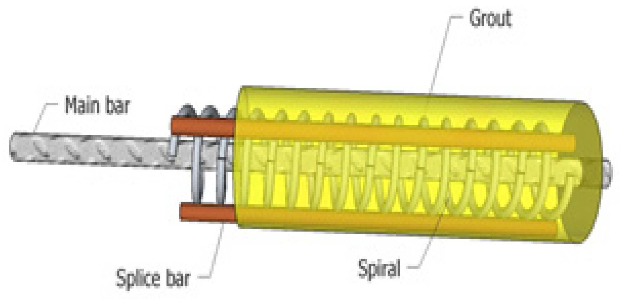
2.1. Beam Specimens and Materials

A total of ten rectangular simply supported reinforced concrete beams were investigated, eight with grouted spiral anchor systems, and two without any anchor system to serve as control specimens. The grouted spiral anchor system consisted of the spiral reinforcement, and four splice bars extending over a portion of the bar’s length and enclosed by the grout, as shown in Figure 1.
All beams were 2100 mm long with a rectangular cross-section of 340 mm × 170 mm. The geometrical dimensions of the beam were designed to fail under bending. No transverse reinforcements were provided in the 650 mm central zone. Steel stirrups for shear reinforcement of 10 mm in diameter at 100 mm spacings were provided in the zones between the applied force and supports. More details and dimensions of the test beams are shown in Figure 2a. The anchor system was located at the end of the beam. The length of the anchor system was 150 mm and the length of the isolating pipe was 1800 mm for unbonded beams. Three LVDTs with gauge lengths of 100 mm were attached to measure beam displacements on the bottom surface of the beam. One LVDT was placed at mid-span whilst the other two LVDTs were placed at 250 mm symmetrical to the beam mid-span. Also, one strain gauge was installed on the GFRP at the location of 16 mm from the end of the grouted spiral anchor, which was intended to measure the tensile strain developed in the reinforced bar during loading (see Figure 2b). The anchor system was located at the end of the beam. More details and dimensions of the test beams are shown in Figure 2.
The rebars used in this investigation as the main reinforcement were smooth and rough GFRPs, as shown in Figure 3. These bars were produced by a local manufacturer. All rebars used were 16 mm in diameter. The ultimate stress and strain for GFRP bars were determined by tensile tests in the laboratory; the values were 323.4 MPa and 2.16%, respectively, and the value of the modulus of elasticity was 14.93 GPa. R6 spiral reinforcements with an inner diameter of 58 mm, 43 mm and 33 mm were used in the grouted spiral anchor system to provide confinement. The pitch distance of all the spiral reinforcements was fixed and approximated to 15 mm. Also, four high-yield steel bars (Y10) were welded to the outer surface of the spiral as shown in Figure 4. Sika Grout-215, with a compressive strength of 65 MPa at 7 days, was used as the grout material for the spiral anchor system. Ready-mix concrete grade 40, with slump of 50 mm to 100 mm, was used for casting the beams. The average cube strength of the concrete in compression was 43.83 MPa at 28 days, as evaluated by tests on three cube specimens.
The preparation of the beam specimen was divided into two stages, as shown in Figure 5. The first stage was the preparation of the grouted spiral anchor system, and the second was the application of concrete to the beam. The beams were designed to ensure the failure of the FRP bar before other compounds. This was accomplished by using a reinforcement ratio smaller than the balanced reinforcement ratio, ρ b .
In the experimental investigation, the following parameters were set: (i) the internal diameter of the spiral, and (ii) the condition of reinforcement bars as either bonded or unbonded. For unbonded FRP bars, PVC pipes with an internal diameter of 20 mm were used to cover and isolate the reinforcement FRP bar from the surrounding concrete, and they served as bond breakers. The specimens were divided into two series.
Series I consisted of beams reinforced with rough GFRP bars and series II consisted of beams reinforced with smooth GFRP bars. Details of the geometric properties of the tested beams are summarized in Table 1 for series I and II.

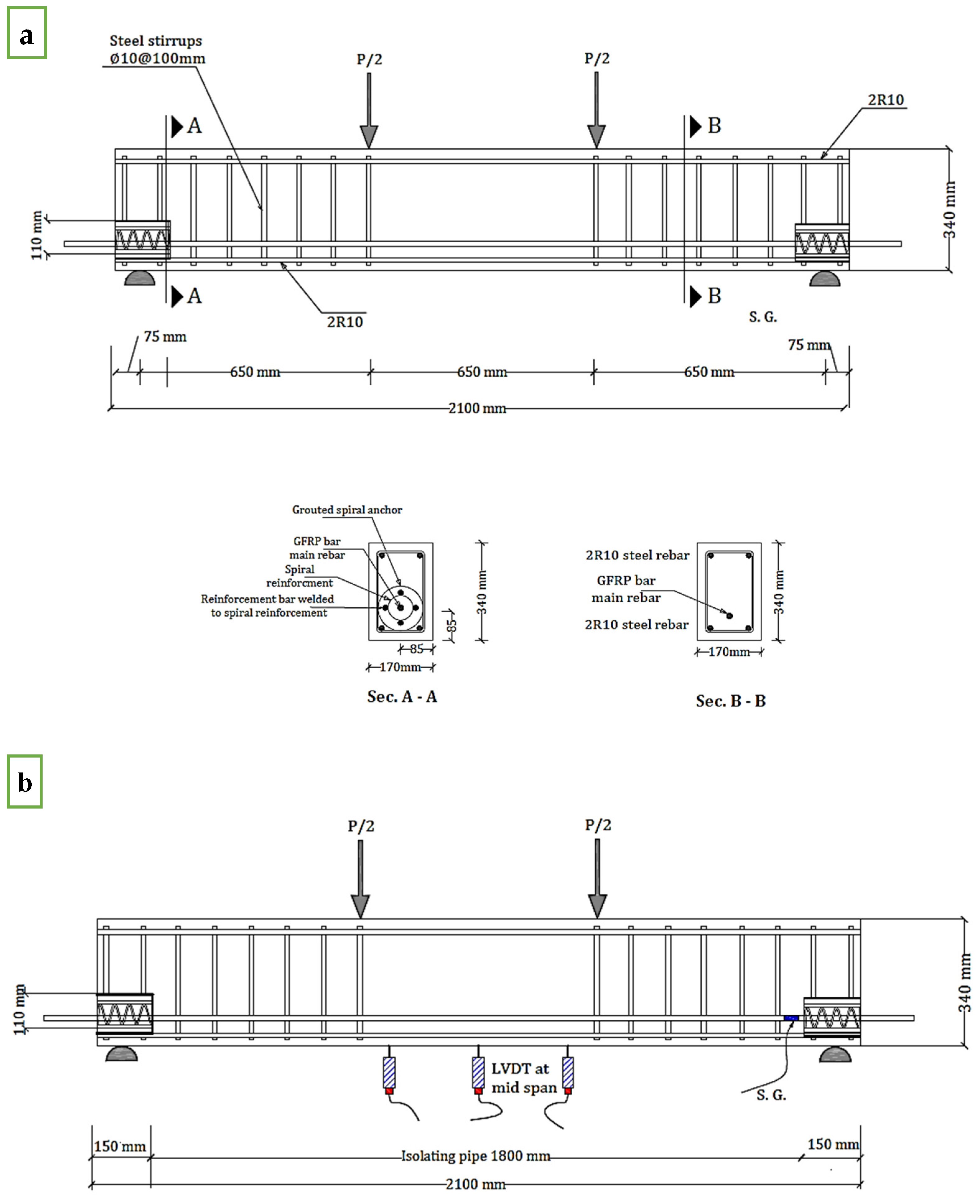
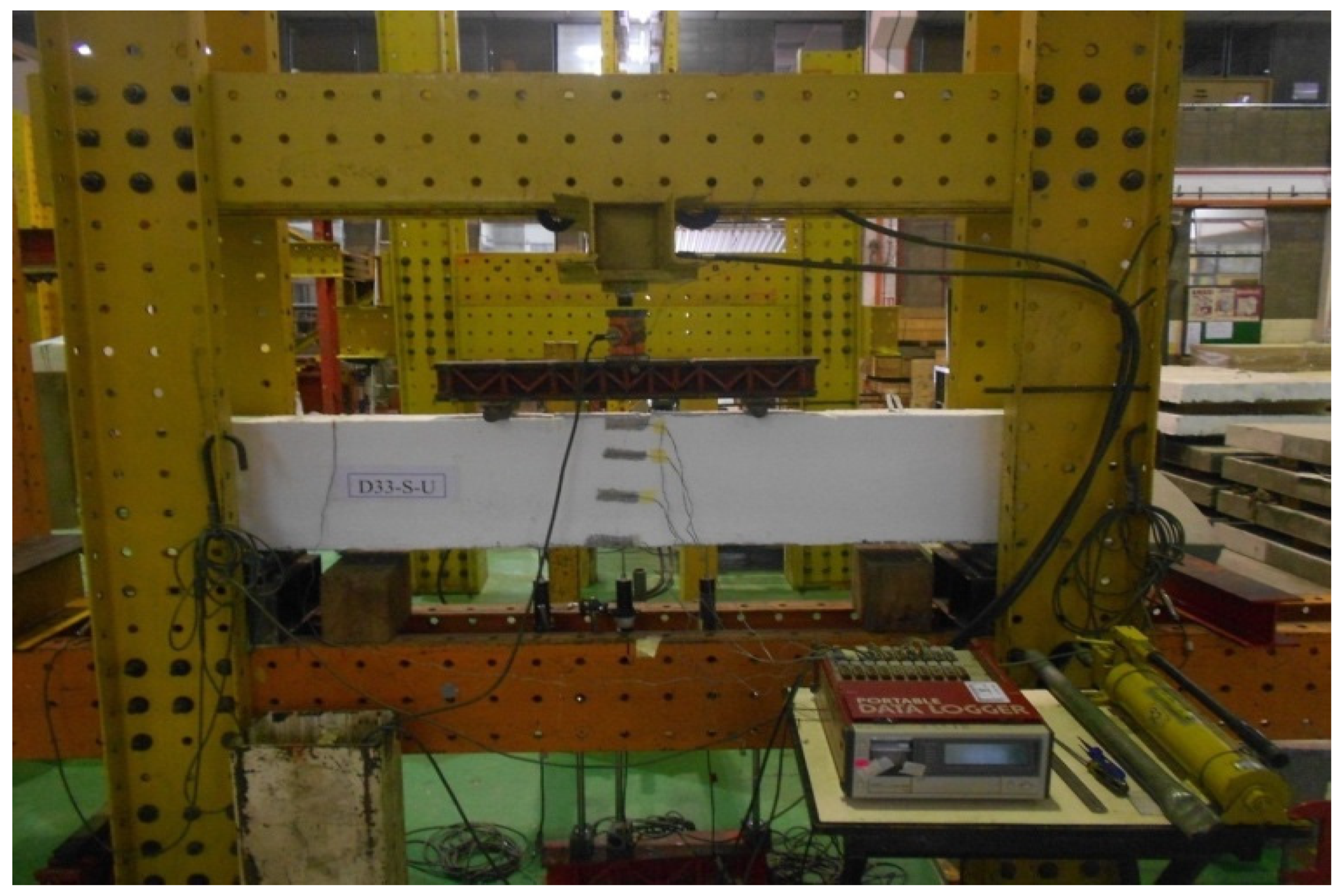
2.2. Test Setup and Test Procedures

All 10 tests were carried out using the same arrangements regarding strain gages and linear variable displacement transducer (LVDT) locations. Strain gauges were glued and fixed to the FRP bar near the spiral anchor. LVDTs were mounted to record the vertical deflections in the beam at mid-span. The beams were placed on half-round supports and subjected to four-point flexural testing, as shown in Figure 6.
The load was applied step by step to the beam, at a rate of 5 kN per step and 0.1 kN after the point of sudden change, using one 300 kN hydraulic jack, and it was measured with a load cell. The load cells, LVDTs, and strain gauges were connected to the data logger to record the applied loads, the vertical deflections in the beam at mid-span at each step of loading, and the strain of the GFRP bar at each loading step. Also, during the testing, cracks were sketched, and the maximum crack widths were measured.
A summary of the overall behavior of the reinforced concrete beams in terms of first-crack strength, ultimate loads, load deflection, number of cracks, and maximum crack width is presented in Section 3.

3. Results and Discussions

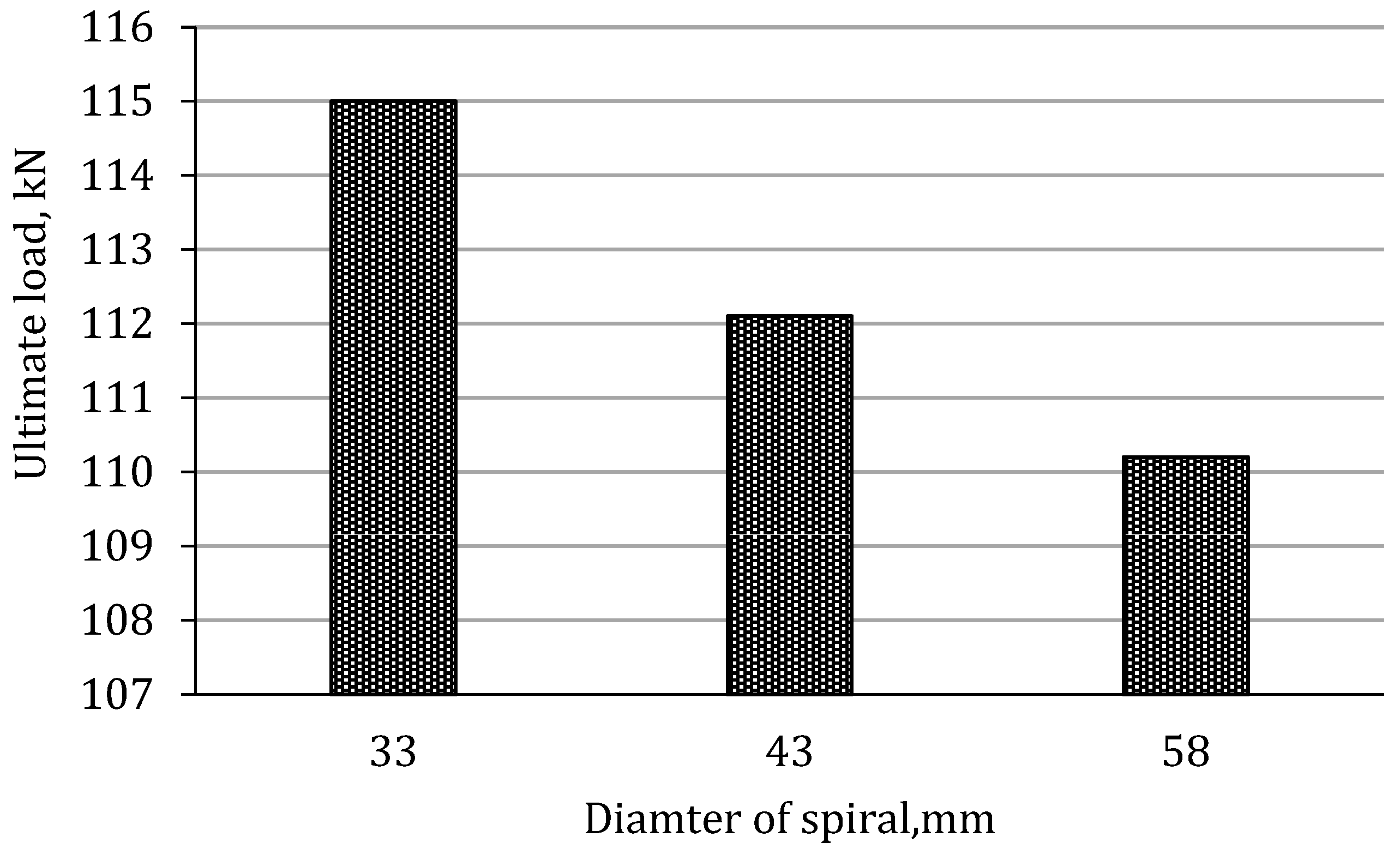
3.1. First-Crack Strength and Ultimate Loads

The results of first-crack strength and ultimate loads for the tested beams are shown in Table 2. In Series I, beams were reinforced with rough GFRP bars; the first-crack load and ultimate load for beam B43-R-B with the spiral anchor system increased by 7.7% and 8.7% compared to that of beam CR without any spiral anchor system. The first-crack load of beam D33-R-U reinforced with unbonded GFRP rebar with a spiral anchor was 65 kN, similar to the first-crack load of beam CR reinforced with bonded GFRP rebar and without any spiral anchor system. The ultimate load of beam D33-R-U decreased slightly, by 2.5%, compared to that of beam CR—refer to Figure 7. This shows that the spiral anchor system alone, without relying on the anchorage bond of GFRP bars, was able to provide flexural strength close to that of beam CR, which relied on the anchorage bond of the rough GFRP bars. In D33-R-U, where the ends of the reinforcement were adequately anchored with a spiral, there is considerable space for reductions in ductility and flexural strength. Studies by Cairns and Zhao [48] have proven this.
Also, the first-crack strength and ultimate load of beam D33-R-U with a spiral diameter of 33 mm increased by 8.3% and 4.4% compared to those of beam D58-R-U, with a spiral diameter of 58 mm. It can be seen that by reducing the spiral diameter, the beam’s ultimate load is increased (see Figure 8).
A decrease in the diameter of the spiral increases the bond strength between the grout and reinforcement bar, and subsequently increases the flexural capacity of the concrete beam. This is because decreasing the spiral diameter decreases the confined cross-sectional area of grout. The cross-sectional area is the area where potential splitting can occur, such as radial cracks. In the case of a spiral with a small diameter, there is a smaller confined cross-sectional area of grout surrounding the spliced bar, which leads to a smaller splitting crack. Therefore, the area of confined grout inside the spiral is suspected to be the main factor that contributes to the confinement, which subsequently increases the bending capacity; refer to Figure 9. Such a result regarding the effect of spiral diameter on the bond strength between the reinforcement bar and the grout was also discovered by previous researchers, such as [39,49,50].
From the above, it can be concluded that the flexural loads are highly affected by the present grouted spiral reinforcement set at the beam ends. The beams with anchor systems were able to sustain higher flexural load than the same beam configurations without end anchor systems. In addition, the ultimate loads were affected by decreases in the diameter of the spiral. The ultimate loads increased as the spiral diameters decreased.
In Series II, beams were reinforced with smooth GFRP bars; the ultimate load for beam D43-S-B reinforced with bonded GFRP rebar and with a spiral anchor exhibited the same ultimate load as beams with CS (see Figure 10).
Furthermore, the test results indicate that the beam reinforced with smooth bars and a spiral anchor system did not show any increase in the first-crack load as compared to the same beam configuration with the spiral anchor system. Also, beam D43-S-U with the spiral diameter of 43 mm exhibited a lower ultimate load than beam D58-S-U, with the spiral diameter of 58 mm. Although decreasing the diameter of the spiral could increase the bond between the reinforcing bar and the grout and subsequently increase the ultimate load, when the spiral diameter was increased from 43 mm to 58 mm, an increase in ultimate load was exhibited (see Figure 11). This shows that the end anchor system is much more effective for beams reinforced with rough FRP bars than those reinforced with smooth FRP bars. This may be due to the mechanisms of bond transfer being different for bars with different surface treatments. For smooth bars, the pull-out behavior is typical of the frication-type slippage behavior at very low bond stress values. The initial bond stiffness is followed by a gradual decrease in bond strength as the contact area decreases when the bar pulls out. Based on the frictional model proposed by Tastani [51], confinement with the spiral improves the bond between smooth bars and concrete by increasing the frictional resistance, which prevents the steel bar from slipping.
However, for bars with rough surfaces, the bar falls during splitting. Such a statement has been proven by Bank et al. [19]. They used scanning electron microscopy to observe the changes in the microstructure of an FRP bar after a pullout test. Large radial and circumferential cracks can be seen in the outer surface of FRP bars with a sand-coated surface (rough FRP bar). The aim of confinement utilizing transverse reinforcement in the form of a spiral or tie is to prevent failure along a potential splitting crack and to prevent shear failure, which is associated with the maximum bond strength [44]. Figure 12 shows the interlocking mechanism between the reinforced bar and the surrounding grout. The grout fills the space between the bar and spiral, and interlocks with the outer surface of the bar (in the case of a rough surface) to resist the slippage of the bar. This allows compressive stress to develop at the bearing area between the grout and the outer surface of the bar, which generates stress acting perpendicularly to the inclined surface of the rib. The resultant stress can be resolved into two componential stresses acting horizontally and normal to the spliced bar [52,53]. However, in the case of a smooth surface, there is an interaction between the bar surface and the surrounding grout. This means that the grouted spiral at the end of the beam is much more effective when using an FRP rough bar than an FRP smooth bar.

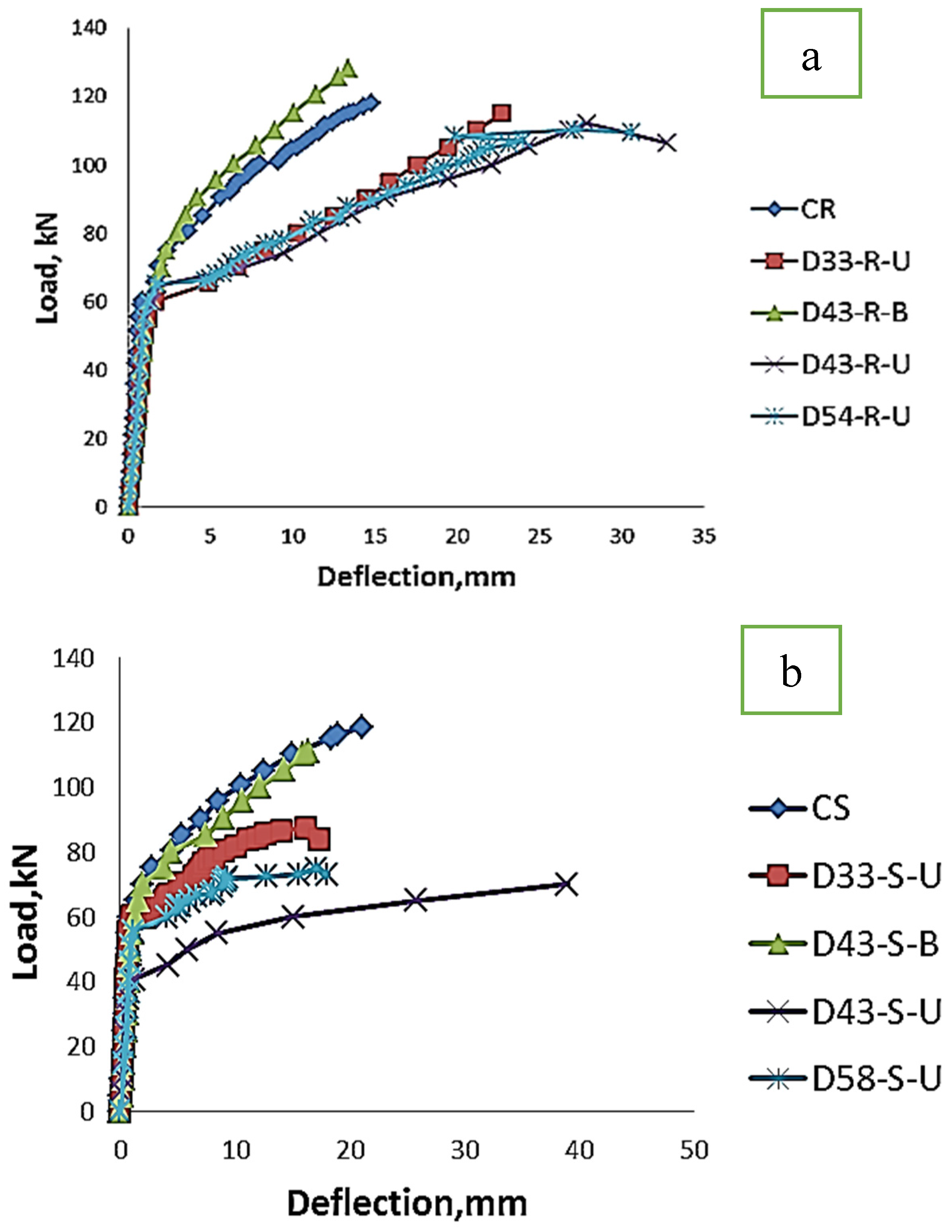
3.2. Load–Deflection Behavior

The relationships between the applied load and mid-span deflection of the 10 beams in series I and II are presented in Figure 13a and Figure 13b, respectively. In Series I, beams were reinforced with rough GFRP bars. Beam CR with rough bars without a spiral anchor had an ultimate load of 117.9 kN and a deflection of 14.9 mm. On the other hand, beam D43-R-B with bonded rough bars and a spiral anchor system showed the ultimate loads of 128.2 kN and 13.32 mm—a slightly improved vertical deflection as compared to beam CR. Beam D58-R-U and D33-R-U, representing beams with unbonded rough bars and spiral anchors of 58 mm and 33 mm diameters, showed the ultimate loads and corresponding deflections (in brackets) of 110.2 kN (27.16 mm) and 115 kN (22.7 mm), respectively. beam D43-R-U, with an unbonded rough bar, showed an ultimate load and deflection of 112.2 kN and 27.87 mm, respectively.
From the above, it can be concluded that the load–deflection behavior is affected by the increase in the diameter of the spiral. As the spiral diameter decreases, the effective spiral area per unit area of grout increases. This means that a larger area of the spiral is involved in generating transverse tensile resistance. As a result, better confinement is generated, and hence, better bond performance is obtained. This finding was also observed by Ling et al. [54].
From the responses in series I, it can be concluded that the beam with bonded rough GFRP reinforcement and a spiral anchor experienced smaller deflection, higher stiffness, and better ultimate strength as compared to the beam with bonded rough reinforcement without a spiral anchor.
In series II, beams were reinforced with a smooth GFRP bar. The results show that sample beam CS without a spiral anchor had the ultimate load of 118.5 kN and the corresponding vertical deflection of 21.08 mm. Beam D43-S-B, with the spiral anchor system, reached the ultimate load of 119.2 kN, with a vertical deflection of 20.43 mm. Beams D58-S-U and D33-S-U had different diameters of spiral and unbonded reinforcement bars. Their ultimate loads and corresponding deflections (in brackets) were 74.9 kN (17.07 mm) and 87.9 kN (16.18 mm), respectively. It can be seen that a smaller spiral diameter increases the ultimate load slightly. Further, beam D43-S-U, with an unbonded reinforced bar, had the ultimate load and corresponding deflection of 70.1 kN and 29.01 mm, respectively.
Referring to Figure 13, although beams reinforced with GFRP reinforcement bars exhibited a linear–elastic behavior up to failure, which can lead to the brittle failure of the beam, introducing 4R10 steel bars at the corners of the beam can significantly improve the beam’s ductility, providing a more gradual and predictable failure. In the tested beams D43-R-U and D54-R-U, the load–deflection curves show a descending trajectory, which suggests that the beams underwent progressive yielding of the steel reinforcement before the GFRP reinforcement’s rupturing; this allowed for strain redistribution and plastic deformation, leading to a more gradual post-peak-load reduction, meaning no sudden failure. These behaviors for beams with unbonded bars are similar to the behaviors of under-reinforced beams. Otherwise, in control beam CR and Beam 43-R-B reinforced with bonded FRP bars, the FRP bars carry most of the tension, and may rupture suddenly before the steel yields. This leads to an abrupt drop in load capacity and a brittle failure mode. The descending branch in the load–deflection curves of these samples is absent.
In addition, the behavior of concrete beams reinforced with unbonded rebar transformed from purely a flexural response to a tied arch when the bond was eliminated. The neutral axis remained horizontal throughout the beam with fully bonded reinforcement. By contrast, the beam with reduced bond showed higher compressive strains at the top face near the mid-span, and the neutral axis increased in depth towards the support. The increase in compressive strains led to a reduction in ductility and flexural strength [48].

3.3. Strains in GFRP Bars
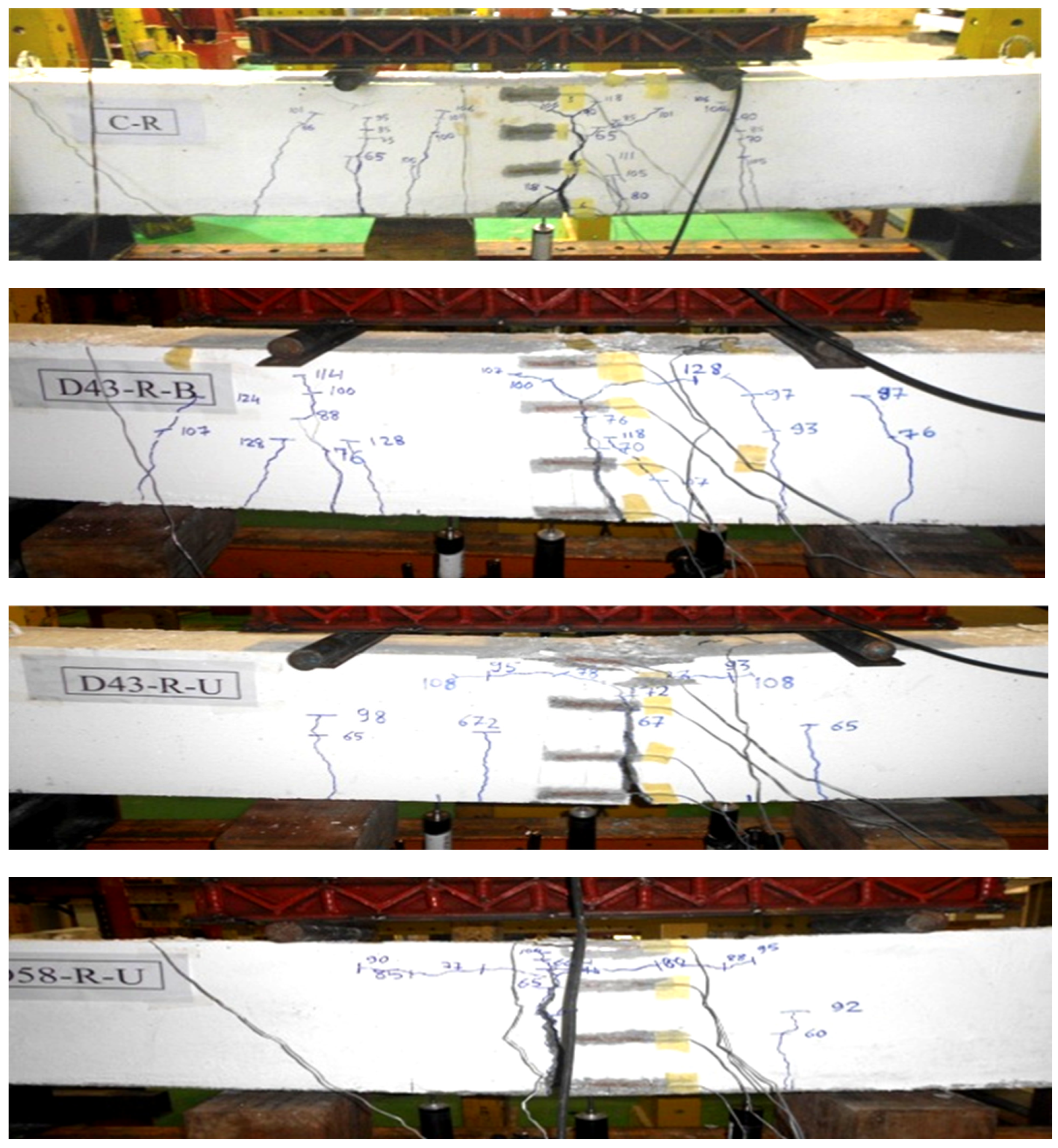
Figure 14 shows the longitudinal strains measured at the end of the GFRP bar in tested beams with bonded GFRP bars. The applied load was here transferred from the concrete to the GFRP bar until the tensile strength of the GFRP bar was exceeded and cracking in the concrete occurred. In Figure 14a, it can be seen that the recorded longitudinal strains at the end of the GFRP bar were affected by the presence of a spiral anchor. When the applied load was close to the ultimate load of 110 kN, for series I, the recorded longitudinal strains in the GFRP bar of beam D43-R-B decreased by 13% as compared to the corresponding strains of the tested beam CR without a spiral anchor.
For series II, the recorded longitudinal strains at the end of the GFRP bar for beams reinforced with bonded bars are shown in Figure 14b. Referring to this figure, it can be seen that the longitudinal strains at the ends of the GFRP bars near the anchors were not affected by the presence of a spiral anchor system, while for the tested beam CS without an end anchor, when the applied load was close to the ultimate load of 110 kN, the strain in the GFRP decreased by 22.8% as compared to the corresponding strain of tested beam D43-S-B.

3.4. Failure Modes

Figure 15 and Figure 16 illustrate the modes of failure for the tested beams reinforced internally with rough and smooth GFRP bars, respectively. The failure mode for all beams was flexural–tension failure. Also, the number of cracks and the average crack width of each beam are given in Table 2. Referring to this table, tested beams CR and CS gave the same ultimate load. Flexural cracks were formed in RC members when the tensile strain in concrete reached its tensile deformation capacity. At the crack, the tensile force was carried by the reinforcement, and it is considered that at a certain distance, usually referred to as the transfer length, composite action can be attained, and both the concrete and the reinforcement will carry the tensile force via the compatibility of their strains. Both smooth and rough bars are made of the same FRP material and have the same cross-sectional area, and so their inherent tensile strengths will be very similar. The ultimate load is primarily governed by the tensile of the FRP material itself. However, to ensure that CR and CS have the same ultimate load, along the transfer length, a slip is assumed, which depends on the bond capacity between the reinforcement and the surrounding material. According to this, the crack width in RC flexural members mainly depends on the bond stress between the concrete and the rebar. CR and CS have different surface conditions and different bond behaviors. The tested beam CR reinforced with rough bar achieved a greater bond than the tested beam CS reinforced with a smooth bar, while CR had a greater number of cracks with smaller crack widths as compared with the tested beam CS.
Referring to Figure 15 and Table 2, it can be noted that beams reinforced with GFRP bars combined with an end anchor exhibited more cracks and smaller average crack spacings compared to the beams without an end anchor. This is made evident by beam D43-R-B reinforced with rough bonded GFRP bars with an end anchor system, which showed eight cracks and a maximum crack width of 8 mm, while the beam without end anchor system (CR) showed fewer cracks of 6 and a higher maximum crack width of 10 mm. In addition, beam D43-S-B reinforced with smooth bonded GFRP bars developed two cracks, which is fewer than specimen CS, which showed three cracks.
For beams reinforced with unbonded rough reinforcing bars, the number of cracks increased from two in beam D58-R-U to three in beam D33-R-U due to a decrease in the diameter of the spiral from 58 mm to 33 mm, while the crack width decreased from 25 mm to 15 mm, due to a decrease in the diameter of the spiral from 58 mm to 33 mm.

4. Conclusions

Experimental investigations were carried out to provide an insight into the behaviors of beams with a spiral anchor system under two-point bending. The main variables were (i) the bar condition, either bonded or unbonded reinforcement bar, and (ii) the diameters of the spiral reinforcements. The discussion of the experimental results takes into account the ultimate loads, the crack widths, and the load–deflection curves until failure. The main conclusions, based on the experimental results, can be summarized as follows:
In the case of rough bars, a spiral system can be used to improve the bending moment capacity by 8.7% compared to that of a beam without any spiral anchor system. This is due to the enhancement of the bond through the anchor system. In addition, the beams reinforced with rough GFRP bars combined with an end anchor exhibited more cracks and smaller average crack spacing compared to beams without an end anchor. However, the end anchor system is not suitable for FRP bars with a smooth surface.
The flexural capacities of the beams reinforced with rough GFRP bars with end anchor systems were highly affected by the spiral diameter. Decreases in spiral diameter improve the confinement stress acting on the grouted spiral, and subsequently increase the bond capacity. For the best bond performance of a spiral in terms of bond capacity, a small spiral diameter of about 33 mm is preferred.
The longitudinal strains at the ends of the GFRP bars were affected by the presence of a spiral anchor. The beams reinforced with GFRP bars combined with an end anchor exhibited lower longitudinal strains when the applied load was close to the ultimate load, compared to the beams without an end anchor.
This area may be explored further using a spiral anchor system with different lengths of embedded bars. The research may also be extended to consider numerical models, such as finite elements, in order to gain a more detailed understanding of the behaviors, componential interactions, and distributions of stress within the beam specimens. The data produced in this research may be used for the validation of finite element models with various parameters, such as spiral diameter and bar size, to optimize the spiral anchor system.

Author Contributions

Conceptualization, A.A.M.F., N.S.M., A.B.A.R., A.K. and T.A.-L.; methodology, A.A.M.F., N.S.M., A.B.A.R., A.K., F.I.T.P. and T.A.-L.; experimental, N.S.M., A.B.A.R., A.K. and E.A.B.A.; software, A.A.M.F., N.S.M., A.B.A.R. and E.A.B.A.; validation, A.A.M.F., N.S.M., A.B.A.R., F.I.T.P. and T.A.-L.; formal analysis, A.A.M.F., N.S.M., A.B.A.R., A.K. and T.A.-L.; investigation, A.A.M.F., N.S.M., A.K. and T.A.-L.; resources, F.I.T.P.; data curation, A.A.M.F., N.S.M., A.K. and T.A.-L.; writing—original draft preparation, A.A.M.F., N.S.M., A.B.A.R. and E.A.B.A.; writing—review and editing, A.A.M.F., N.S.M. and F.I.T.P.; visualization, T.A.-L.; supervision, A.A.M.F., A.B.A.R., T.A.-L. and F.I.T.P.; project administration, F.I.T.P.; funding acquisition, F.I.T.P. All authors have read and agreed to the published version of the manuscript.

Funding

This research received no external funding.

Data Availability Statement

All data used are presented here.

Conflicts of Interest

The authors declare no conflicts of interest.

References

  1. ACI Committee440. Guide For the Design and Construction of Concrete Reinforced with FRP Bars, 440.1R-03; American Concrete Institute: Farmington Hills, MI, USA, 2003. [Google Scholar]
  2. Zhou, Z.; Ou, J.P.; Wang, B. Smart FRP-OFGB bars and their application in reinforced concrete beams. In Proceedings of the First International Conference on Structural Health Monitoring and Intelligent Structure, Tokyo, Japan, 13–15 November 2003; pp. 861–866. [Google Scholar]
  3. Tighiouart, B.; Benmokrane, B.; Gao, D. Investigation of Bond in Concrete Member with Fibre Reinforced Polymer (FRP) Bars. Constr. Build. Materials. 1998, 12, 453–462. [Google Scholar] [CrossRef]
  4. Lazorenko, G.; Kasprzhitskii, A.; Nazdracheva, T. Anti-corrosion coatings for protection of steel railway structures exposed to atmospheric environments: A review. Constr. Build. Mater. 2021, 288, 123115. [Google Scholar] [CrossRef]
  5. Keesler, R.J.; Powers, R.G. Corrosion of Epoxy Coated Rebars Keys Segmental Bridge Monroe County; Report No. 88-8A; Florida Department of Transportation, Materials Office, Corrosion Research Laboratories: Gainesville, FL, USA, 1988. [Google Scholar]
  6. Smith, J.L.; Virmani, Y.P. Materials and Methods for Corrosion Control of Reinforced and Prestressed Concrete Structures in New Construction; (No. FHWA-RD-00-081) United States; Federal Highway Administration: Washington, DC, USA, 2000. [Google Scholar]
  7. Aljibori, H.S.; Alamiery, A.; Kadhum, A.A.H. Advances in corrosion protection coatings: A comprehensive review. Int. J. Corros. Scale Inhib. 2023, 12, 1476–1520. [Google Scholar]
  8. Jerrett, C.V.; Ahmad, S.H. Bond Tests of Carbon Fibre Reinforced Plastic (CFRP) Rods. In Non-Metallic (FRP) Reinforcement for Concrete Structures: Proceedings of the Second RILEM International Symposium, Ghent, Belgium, 23–25 August 1995; CRC Press: Boca Raton, FL, USA, 1995; pp. 180–191. [Google Scholar]
  9. Acciai, A.; D’Ambrisi, A.; De Stefano, M.; Feo, L.; Focacci, F.; Nudo, R. Experimental Response of FRP Reinforced Members without Transverse Reinforcement: Failure Modes and Design Issues. Compos. Part B Eng. 2016, 89, 397–407. [Google Scholar] [CrossRef]
  10. Iyer, S.L.; Sen, R. (Eds.) Advanced Composite Materials in Civil Engineering Structures. In Proceedings of the Specialty Conference, Seattle, WA, USA, 25–27 June 1991; American Society of Civil Engineers: Reston, VA, USA, 1991. [Google Scholar]
  11. Neale, K.W.; Labossiere, P. Advanced Composite Materials in Bridges and Structures. In Proceedings of the First International Conference (ACMBS-I), Sherbrooke, QC, Canada; 1992. [Google Scholar]
  12. White, T.D. Composite Materials and Structural Plastics in Civil Engineering Construction. In Proceedings of the Materials Engineering Congress, New York, NY, USA, 10–12 August 1992; American Society of Civil Engineers: New York, NY, 1992; pp. 532–718. [Google Scholar]
  13. Taerwe, L. FRP Activities in Europe: Survey of Research and Applications. Proc. Third Int. Symp. Non Met. (FRP) Reinf. Concr. Struct. (FRPRCS-3) 1997, 1, 59–74. [Google Scholar]
  14. Benmokrane, B.; Rahman, H. Durability of Fiber Reinforced Polymer (FRP) Composites for Construction. In Proceedings of the First International Conference (CDCC ’98), Sherbrooke, QC, Canada, 5–7 August 1998. [Google Scholar]
  15. Saadatmanesh, H.; Ehsani, M.R. Fiber Composites in Infrastructure. In Proceedings of the Second International Conference on Composites in Infrastructure (ICCI-98), Tucson, AZ, USA, 12–14 January 1998. [Google Scholar]
  16. Dolan, C.W.; Rizkalla, S.H.; Nanni, A. Fiber reinforced polymer reinforcement for reinforced concrete structures. In Proceedings of the 4th International Symposium, Baltimore, MD, USA, 31 October–5 November 1999; American Concrete Institute: Farmington Hills, MI, USA, 1999. [Google Scholar]
  17. You, Y.J.; Park, K.T.; Seo, D.W.; Hwang, J.H. Tensile Strength of GFRP Reinforcing Bars with Hollow Section. Adv. Mater. Sci. Eng. 2015, 2015, 621546. [Google Scholar] [CrossRef]
  18. GangaRao, H.V.; Taly, N.; Vijay, P.V. Reinforced Concrete Design with FRP Composites; CRC Press: Boca Raton, FL, USA, 2019. [Google Scholar]
  19. Bank, L.C.; Puterman, M.; Katz, A. The Effect of Material Degradation on Bond Properties of Fiber Reinforced Plastic Reinforcing Bars in Concrete. ACI Mater. J. 1998, 95, 232–243. [Google Scholar]
  20. Harajli, M.; Abouniaj, M. Bond Performance of GFRP Bars In Tension: Experimental Evaluation and Assessment of ACI 440 Guidelines. J. Compos. Constr. 2010, 14, 659–668. [Google Scholar] [CrossRef]
  21. Schmidt, J.W.; Bennitz, A.; Täljsten, B.; Goltermann, P.; Pedersen, H. Mechanical anchorage of FRP tendons–a literature review. Constr. Build. Mater. 2012, 32, 110–121. [Google Scholar] [CrossRef]
  22. Hu, Z.; Shah, Y.I.; Yao, P. Experimental and numerical study on interface bond strength and anchorage performance of steel bars within prefabricated concrete. Materials 2021, 14, 3713. [Google Scholar] [CrossRef]
  23. Wang, Q.; Li, T.; Zhu, H.; Su, W.; Hu, X. Bond enhancement for NSM FRP bars in concrete using different anchorage systems. Constr. Build. Mater. 2020, 246, 118316. [Google Scholar]
  24. Ling, J.H.; Rahman, A.B.A.; Ibrahim, I.S. Feasibility Study of Grouted Splice Connector under Tensile Load. Constr. Build. Mater. 2014, 50, 530–539. [Google Scholar]
  25. Alias, A.; Sapawi, F.; Kusbiantoro, A.; Zubir, M.A.; Rahman, A.B.A. Performance of Grouted Splice Sleeve Connector under Tensile Load. J. Mech. Eng. Sci. 2014, 7, 1094–1102. [Google Scholar]
  26. Einea, A.; Yamane, T.; Tadros, M.K. Grout-Filled Pipe Splices for Precast Concrete Construction. PCI J. 1995, 40, 82–93. [Google Scholar] [CrossRef]
  27. Untrauer, R.E.; Henry, R.L. Influence of Normal Pressure on Bond Strength. ACI J. 1965, 62, 577–586. [Google Scholar]
  28. Robins, P.J.; Standish, I.G. The Influence of Lateral Pressure upon Anchorage Bond. Mag. Concr. Res. 1984, 36, 195–202. [Google Scholar]
  29. Moosavi, M.; Jafari, A.; Khosravi, A. Bond of Cement Grouted Reinforcing Bars Under Constant Radial Pressure. Cem. Concr. Compos. 2005, 27, 103–109. [Google Scholar]
  30. Xu, F.; Wu, Z.; Zheng, J.; Hu, Y.; Li, Q. Experimental Study on the Bond Behavior of Reinforcing Bars Embedded in Concrete Subjected to Lateral Pressure. J. Mater. Civ. Eng. 2011, 24, 125–133. [Google Scholar]
  31. Taniguchi, H.; Mutsuyoshi, H.; Kita, T.; Machida, A. Ductile behavior of beams using FRP as tendons and transverse reinforcement. In Proceedings of the International Symposium Fiber-Reinforced-Plastic Reinforcement for Concrete Structures, Vancouver, BC, Canada, 28–31 March 1993; Nanni, A., Dolan, C., Eds.; Special Publication: Vancouver, BC, Canada, 1993. [Google Scholar]
  32. Fam, A.; Cole, B.; Mandal, S. Composite Tubes as an Alternative to Steel Spirals for Concrete Members in Bending and Shear. Constr. Build. Mater. 2007, 21, 347–355. [Google Scholar]
  33. Loh, H.Y. Development of Grouted Splice Sleeve and Its Performance Under Axial Tension. Ph.D. Thesis, Universiti Teknologi Malaysia, ohor Darul Ta’zim, Malaysia, 2008. [Google Scholar]
  34. Loo, G.K. Parametric Study of Grout-Filled Splice Sleeve Integarated with Flexible Aluminium Tube for Precast Concrete Connection. Ph.D. Thesis, Universiti Teknologi Malaysia, ohor Darul Ta’zim, Malaysia, 2009. [Google Scholar]
  35. Ling, J.H.; Rahman, A.B.; Ibrahim, I.S.; Abd, Z. Tensile performance of ribbed hollow section splice sleeve connector under direct tensile load. In Proceedings of the 2nd Construction Industry Research Achievement International Conference (CIRAIC 2009), Kuala Lampur, Malaysia, 3–5 November 2009. [Google Scholar]
  36. Soroushian, P.; Choi, K.B.; Park, G.H.; Aslani, F. Bond of Deformed Bars to Concrete: Effects of Confinement and Strength of Concrete. ACI Mater. J. 1991, 88, 227–232. [Google Scholar]
  37. Lim, C.T. The Effect of Pitch Distance of Steel Spiral Reinforcement to the Performance of Grouted Sleeve Connector under Direct Tensile Load. Ph.D. Thesis, Universiti Teknologi Malaysia, ohor Darul Ta’zim, Malaysia, 2010. [Google Scholar]
  38. Lee, G.S. Parametric Studies of Sleeve Connector Using Steel Pipe with Spiral Steel for Precast Concrete Connection. Ph.D. Thesis, Universiti Teknologi Malaysia, ohor Darul Ta’zim, Malaysia, 2009. [Google Scholar]
  39. Hosseini, S.J.A.; Rahman, A.B.A. Effects of Spiral Confinement To The Bond Behavior of Deformed Reinforcement Bars Subjected to Axial Tension. Eng. Struct. 2016, 112, 1–13. [Google Scholar] [CrossRef]
  40. Guizani, L.; Chaallal, O. An Experimental Study on Bond-Slip in Moderately Confined Concrete Subjected to Monotonic and Cyclic Loading Using an Experimental Plan. Can. J. Civ. Eng. 2011, 38, 272–282. [Google Scholar]
  41. ACI Committee 408. Bond and Development of Straight Reinforcing Bars in Tension; ACI 408R-03; American Concrete Institute: Farmington Hills, MI, USA, 2003. [Google Scholar]
  42. Hamad, B.; Rteil, A. Comparison of roles of FRP sheets, stirrups, and steel fibers in confining bond critical regions. ASCE J. Compos. Constr. 2006, 10, 330–336. [Google Scholar] [CrossRef]
  43. Giuriani, E.; Plizzari, G.; Schumm, C. Role of Stirrups and Residual Tensile Strength of Cracked Concrete on Bond. J. Struct. Eng. 1991, 117, 1–18. [Google Scholar] [CrossRef]
  44. Rao, G.A. Parameters Influencing Bond Strength of Rebars in Reinforced Concrete. Int. J. Appl. Eng. Technol. 2014, 4, 72–81. [Google Scholar]
  45. Fadiel, A.; Mohammed, N.; Abdul Rahman, A.B.; Ali, E.A.B.; Abu-Lebdeh, T. Performance of Polyester Grouted Connector for Splicing of Reinforcement Bars. Am. J. Eng. Appl. Sci. 2024, 17, 46–50. [Google Scholar] [CrossRef]
  46. Fadiel, A.A.; Mohammed, N.S.; Rahman, A.B.A.; Ali, E.A.B.; Abu-Lebdeh, T.; Petrescu, F.I.T. Effect of Fly Ash on Mechanical Properties of Polymer Resin Grout. Biomimetics 2023, 8, 392. [Google Scholar] [CrossRef] [PubMed]
  47. Gilbert, R.I.; Mickleborough, N.C. Design of Prestressed Concrete; CRC Press: Sydney, Australia, 1990. [Google Scholar]
  48. Cairns, J.; Zhao, Z. Behavior of concrete beams with exposed reinforcement. Proc. Inst. Civ. Eng. Struct. Build. 1993, 99, 141–154. [Google Scholar] [CrossRef]
  49. Mohammed, N.S. Behaviour and Performance of Non-Cement Polymer Grouted Spiral Connection. Ph.D. Thesis, Universiti Teknologi Malaysia, Skudai, Malaysia, 2019. [Google Scholar]
  50. Einea, A.; Yehia, S.; Tadros, M.K. Lap Splices in Confined Concrete. ACI Struct. J. 1999, 96, 937–994. [Google Scholar]
  51. Tastani, S.P.; Pantazopoulou, S.J. Experimental Evaluation of the Direct Tension-Pullout Bond Test. In Proceedings of the Symposium on “Bond in Concrete—From Research to Standards”, Budapest, Hungary, 20–22 November 2002; pp. 268–276. [Google Scholar]
  52. Brenes, F.J.; Wood, S.L.; Kreger, M.E. Anchorage Requirements for Grouted Vertical-Duct Connectors in Precast Bent Cap Systems; Project Summary Report 0-4176; Center for Transportation Research, The University of Texas at Austin: Austin, TX, USA, 2006; p. 252. [Google Scholar]
  53. Thompson, M.; Jirsa, J.; Breen, J.; Klingner, R. Anchorage Behaviour of Headed Reinforcement: Literature Review; University of Texas: Austin, TX, USA, 2002. [Google Scholar]
  54. Ling, J.H.; Rahman AB, A.; Ibrahim, I.S.; Hamid, Z.A. Tensile capacity of grouted splice sleeves. Eng. Struct. 2016, 111, 285–296. [Google Scholar]
Figure 1. The anchor system.
Jcs 09 00149 g001
Figure 2. The details of the beams: (a) details and dimensions of tested beams; (b) locations of strain gauge S.G. and LVDT.
Jcs 09 00149 g002
Figure 3. Smooth and rough FRP bar.
Jcs 09 00149 g003
Figure 4. Spiral and splice bars.
Jcs 09 00149 g004
Figure 5. Preparation of the beam specimens: (a) GFRP bars with a grouted spiral anchor system; (b) reinforced concrete beams with a spiral anchor system.
Jcs 09 00149 g005
Figure 6. Test setup.
Jcs 09 00149 g006
Figure 7. Ultimate load for beams CR, D33-R-U and D43-R-B.
Jcs 09 00149 g007
Figure 8. Ultimate loads for beams reinforced with rough bar D33-R-U, D43-R-U and D58-R-U versus the diameter of the spiral.
Jcs 09 00149 g008
Figure 9. Confined cross-sectional areas of grout with different spiral diameters [49].
Jcs 09 00149 g009
Figure 10. Ultimate load for beams CS, D33-S-U and D43-S-B.
Jcs 09 00149 g010
Figure 11. Ultimate loads for beams reinforced with rough bar D33-S-U, D43-S-U and D58-S-U versus diameter of spiral.
Jcs 09 00149 g011
Figure 12. Interlocking mechanism between the spliced bar and the surrounding grout.
Jcs 09 00149 g012
Figure 13. Load vs. mid-span deflection graphs for series I and series II: (a) beams reinforced with rough GFRP bars in series I; (b) beams reinforced with smooth GFRP bars in series II.
Jcs 09 00149 g013
Figure 14. Relation between the load and the strains recorded at the ends of GFRP bars and near the anchors for tested beams reinforced with bonded GFRP bars: (a) beams reinforced with rough GFRP bars in series I; (b) beams reinforced with smooth GFRP bars in series II.
Jcs 09 00149 g014
Figure 15. Mode of failure and crack pattern for beams reinforced with smooth GFRP bars in series I.
Jcs 09 00149 g015aJcs 09 00149 g015b
Figure 16. Mode of failure and crack pattern for beams reinforced with smooth GFRP bars in series II.
Jcs 09 00149 g016aJcs 09 00149 g016b
Table 1. Properties of tested beams.
Tested Beam
and Labels
Diameter of Spiral Reinforcement for the Anchor SystemTypes of Bond Along the GFRP Bar
Series I:
Beams reinforced with rough GFRP bars.
CRNo spiralBonded
D33-R-U33 mmUnbonded
D43-R-B43 mmBonded
D43-R-U43 mmUnbonded
D58-R-U58 mmUnbonded
Series II:
Beams reinforced with smooth GFRP bars.
CSNo spiralBonded
D33-S-U33 mmUnbonded
D43-S-B43 mmBonded
D43-S-U43 mmUnbonded
D58-S-U58 mmUnbonded
Table 2. Results of the flexural load test.
Tested BeamFirst-Crack Strength (kN)Ultimate
Load
(kN)
Mid-Span Displacement
at Ultimate Load (mm)
No. of Cracks
at
Failure
Maximum Crack Width (mm)
Series ICR65117.914.8610
D33-R-U6511522.7315
D43-R-B70128.213.3288
D43-R-U65112.127.87420
D58-R-U60110.227.16225
Series IICS60118.521.08220
D33-S-U6087.516.18312
D43-S-B60119.220.4335
D43-S-U5570.129.01320
D58-S-U6074.917.07130
Disclaimer/Publisher’s Note: The statements, opinions and data contained in all publications are solely those of the individual author(s) and contributor(s) and not of MDPI and/or the editor(s). MDPI and/or the editor(s) disclaim responsibility for any injury to people or property resulting from any ideas, methods, instructions or products referred to in the content.

