Abstract
This paper develops an unmanned aerial vehicle (UAV) deployment scheme in the context of the directional modulation-based secure precise wireless transmissions (SPWTs) to achieve more secure and more energy efficiency transmission, where the optimal UAV position for the SPWT is derived to maximize the secrecy rate (SR) without frequency diverse array (FDA) and injecting any artificial noise (AN) signaling. To be specific, the proposed scheme reveals that the optimal position of UAV for maximizing the SR performance has to be placed at the null space of Eves channel, which impels the received energy of the confidential message at the unintended receiver deteriorating to zero, whilst benefits the one at the intended receiver by achieving its maximum value. Moreover, the highly cost FDA structure is eliminated and transmit power is all allocated for transmitting a useful message which shows its energy efficiency. Finally, simulation results verify the optimality of our proposed scheme in terms of the achievable SR performance.
1. Introduction
1.1. Background and Related Works
As a potential candidate for benefiting wireless transmission in physical layers [1,2,3,4], the directional modulation (DM) technique has attracted extensive attention from the fact that DM can transmit a confidential signal to a specific direction [5,6,7]. Technically, DM is generally employed in two fashions: one is implemented on the radio frequency (RF) frontend, employing the phased array (PA) to optimize the phase shift [5] while another one is implemented on the baseband by utilizing orthogonal vector [6] or beamforming operations [7]. Due to the broadcast nature of DM-based wireless communications, security issues are unavoidable since the distance dimension of DM is threatened by the unintended facility, although DM has an ability to enable the security in a directional aspect. To address this problem, the authors of [8] proposed a linear frequency diverse array (LFDA) method to achieve SPWT. However, the direction angle and distance achieved by LFDA may be coupled, which means that there may exist multiple directions and distances receiving the same confidential message as the desired users. As a further advancement, a number of DM schemes taking the advantage of random frequency diverse array (RFDA) [9,10,11] have been proposed to achieve secure precise wireless transmission (SPWT) for both the direction and distance domains in which the frequency is randomly allocated on each transmit antenna and the correlation direction and distance are decoupled.
Thereafter, SPWT develops repidly. In [12], the authors proposed two practical random subcarrier selection schemes which increase the randomness of subcarriers based on the random FDA, moreover it improves the stability of the SPWT system since a more random selected subcarriers lead to a better performance. In [13], a hybrid beamforming scheme with hybrid digital and analog SPWT structure was proposed, which reduces the circuit budget with low computational complexity and comparable secrecy performance, it significantly increases the practicability of SPWT system. Since the wireless propagation channel results in the security problem becoming more formidable due to the accessibility of diverse devices. For [14] as an example, the authors clarify that the energy of the main lobe is always formed around the desired receiver, but a number of the non-negligible side lobes remain having comparatively appreciable power. It is indicated that the position of the transmitter affects the distribution of those lobes, and then leading to a security risk. To elaborate a little, when the eavesdropper is located on the side-lobe peak, the achievable secrecy rate (SR) performance will be gravely degraded. Therefore, deploying the transmitter at an appropriate position has an important meaning for the secrecy performance.
As a matter of fact, most existing works regarding the SPWT focus on static scenarios, which severely limits its application. Considering that unmanned aerial vehicle (UAV) has been widely utilized in wireless communications due to bringing extensive benefits (e.g., high probability air-to-ground channel [15] and mobility controllable [16]). Moreover, UAV transmission technology has been researched wildly. In [17], the authors presented an UAV autonomous landing scheme with model predictive controlled moving platform. The authors in [18] proposed a novel approach for the Drone-BS in 5G communication systems, using the meta-heuristic algorithm. Ref. [19] considered the UAV-enabled networks under the probabilistic line-of-sight channel model in complex city environments and jointly optimize the communication connection, the three-dimensional (3D) UAV trajectory, and the transmit power of the UAV to increase the average secrecy rate. In [20], the authors consider UAV networks for collecting data securely and covertly from ground users, a full-duplex UAV intends to gather confidential information from a desired user through wireless communication and generate artificial noise (AN) with random transmit power in order to ensure a negligible probability of the desired user’s transmission being detected by the undesired users. The authors in [21] proposed a detection strategy based on multiple antennas with beam sweeping to detect the potential transmission of UAV in wireless networks. In [22], a novel framework is established by jointly utilizing multiple measurements of received signal strength from multiple base stations and multiple points on the trajectory to improve the localization precision of UAV. In [23], the authors considered the region constraint and proposed a received-signal-strength-based optimal scheme for drones swarm passive location measurement. Thus, in this work we consider SPWT in the context of UAV networks, which not only extends the static scenarios to the dynamic situations but also matches the stringent requirement of SPWT for line-of-sight (LoS) communication link from the transmitter to receiver.
1.2. Motivation
Note that in the previous works (e.g., [9,10,11]), the authors consider the SPWT system model only in two-dimensional scenarios, which limits the practical applications scenarios. At the same time, the FDA technique is generally employed to determine a specific position, while this work casts off the high-cost FDA scheme but ingeniously achieves this goal by fully taking advantage of the angle information in the three-dimensional (3D) space. Against this background, this paper considers an SPWT scheme with the aid of a UAV to improve the system’s security level. For a removable UAV transmitter, an analytical solution to the optimal UAV position is derived for reducing the computational complexity. Finally, simulation results show the efficiency of the proposed UAV deployment scheme in terms of the achievable SR performance.
1.3. Contributions
In this paper, the main contributions are as follows.
- We propose a novel SPTW framework with UAV secure communications which improves transmission security by change UAV’s position.
- Proposed UAV SPWT scheme is based on DM but not FDA, which can reduce the radio frequency chains’ cost. Meanwhile, the computational complexity will be significantly reduced.
- Conventional SPWT improves security performance with aided AN, while our proposed scheme deploys the transmitter, e.g., UAV on the zero SINR space of Eve, and the power originally allocated to artificial noise can be used to transmit useful information, which greatly improves Bob’s signal-to-interference-and-noise ratio (SINR) without affecting Eve’s SINR, thus enhancing the security performance.
The remainder of this paper is organized as follows: in Section 2, our system model of proposed UAV SPWT is described, then the secrecy capacity performance based on UAV SPWT structure and proposed UAV deployment scheme is analyzed. Section 3 presents the simulation and the analysis. Finally, the conclusion is drawn in Section 4.
Notations: In this paper, scalar variables are denoted by italic symbols, vectors, and matrices are denoted by letters of bold upper case and bold lower case, respectively. Sign , and denote transpose, conjugation, trace, and conjugate transpose, respectively. and denote the norm and modulus, respectively. denotes expectation operation.
2. Method
2.1. System Model
As shown in Figure 1, our considered SPWT system is composed of an UAV, a desired user (Bob) and an eavesdropper (Eve). Herein, both Bob and Eve are equipped with a single antenna while the UAV is equipped with a rectangular antenna array, namely the distance between any two adjacent antenna elements is identical. It should be noted that, the antennas array should be any planar array, such as rectangular array or circular array which can form both angle and distance depended 3D beams, in this paper, without loss generality we assume the transmit antenna forms a rectangular antenna array. For expression convenience, we set Bob as the origin and the ray formed from Bob to Eve is defined as the positive direction of the X-axis. Moreover, we considered that Bob and Eve are ground users, i.e., the Z-axis coordinates of both Bob and Eve are 0. We assume that the UAV flies at a predetermined height g and parallel to the ground. The channels between the users (Bob or Eve) are assumed as LoS channels which have been widely used in UAV communication scenarios [24]. What is more important, it is difficult for SPWT of applying in None-LoS (NLoS) channels, the reasons are as follows: Firstly, as NLOS channel is independent on and R, the designed beamforming vectors have the possibility of transmitting the confidential signal to any location. As a result, the security performance might be seriously degraded. Secondly, as for NLOS channels, it changes with time, the designed beamforming vectors can be only applied for a specific time. Therefore, with the designed beamforming vectors in NLOS channel, confidential message may be transmitted to any location as time goes. Lastly, in our proposed scheme, the invoked artificial noise (AN) has an ability of disturbing the signal received at Eve, but having a negligible effect on Bob. However, in NLOS channels, there exists an effect of gathering AN for Bob, thus resulting in a serious secrecy rate performance degradation at Bob. Thus, the assumption of the LoS channel in our proposed UAV and SPWT system is completely reasonable.
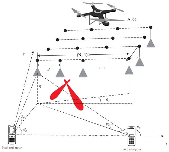
Figure 1.
System model.
Due to the UAV serving the ground users, the relative positions of Bob and Eve is assumed to be known by the UAV. Rationality analysis of this assumption is as follows. For Bob, it is reasonable that the UAV knows his target user’s location. For Eve, we consider a large number of users in our system, and all the users’ location (including desired users, undesired users, and eavesdroppers) are known for Alice. The part of undesired users are legitimate users in other time periods and they will not eavesdrop the the confidential message. The other part of eavesdroppers are illegitimate users in all the time, however, the eavesdroppers hidden in all the users, who is an undesired user or who is an eavesdropper can not be determined. Thus, we can not determine which user is an eavesdropper, but can consider a user who is most likely to be a eavesdropper. This scheme is obviously more reasonable and practical, and thus the Eve in our proposed system model is the most likely eavesdropper, and we try to prevent his eavesdropping by our proposed scheme. In conclusion, the assumption that the relative positions of Bob and Eve is known to the UAV.
According to the definition, the 3D coordinates of Bob is , of Eve is while of the UAV is . Moreover, is the yawing angle between a UAV-filed direction and X-axis. Then, based on the established 3D rectangular coordinate system, the angle relationship among UAV, Bob, and Eve can be derived. Specifically, the azimuth angle of Bob with respect to UAV follows and , while the azimuth angles of Eve with respect to UAV satisfies and . Owing to the existence of , the azimuth angles with respect to the antenna array of the UAV are given by and , respectively. Similarly, the pitch angles of Bob and of Eve related to the UAV can be, respectively, derived as and , where both and satisfy .
Due to UAV being a rectangular antenna array, we define the array parallel to the flight direction as the row, whilst arrays perpendicular to the direction of flight as columns. As such, the subscripts m and n are used to denote the m-th row and n-th column of the rectangular antenna array. Then, the steering vector for the antenna array is expressed as
where and respectively denote the receiver’s azimuth angle and the pitch angle relative to the UAV, where is
Herein, is the central carrier frequency, is the element spacing in the transmit antenna array and c is the speed of light. Substituting and into (1) and (2), respectively, we obtain the steering vector and .
At the baseband, the transmit signal can be expressed as
where , and x refer to the power allocation factor, total transmit power and a complex symbol following . In addition, and denote the beamforming and AN vectors, respectively.
To achieve precise transmission, is set to maximize the received power of the confidential signal at Bob, while is to project the AN into the null space of Bob, where is an AN vector consisting of complex Gaussian variables with normalized power, i.e., . Notably, UAV is usually an aerial platform serving for terrestrial nodes, hence all the communication channels follow the light of sight (LOS) model. Then, the received signal at Bob can be expressed as
while the received signal at Eve is
In (4) and (5), and are the abbreviations of and , respectively. Moreover, and are the additive white Gaussian noises (AWGNs) at Bob and Eve satisfying and .
In this subsection, we propose the system model and give the received signal expression, it is clear to find that the received signal at Bob is independent of the UAV position while the the received signal at Eve is related to which is a function of UAV position information, e.g., . This shows that it is feasible to reduce the useful signal energy at Eve by moving the position of UAV without reducing the useful signal energy at Bob, so as to increase the security of UAV-based SPWT system.
2.2. Proposed UAV Deployment Schemes
In accordance with (4), the SPWT employs to impel the power of the confidential message at the desired receiver achieving its maximum. However, such a conventional SPWT does not guarantee the power received by Eve at a minimum level, since the channel spanning from UAV to Eve (i.e., ) is affected by the relative position of them. As a result, the security for the transmission of the confidential signal is unable to completely ensured. To further enhance the security level of the UAV-dominated moving network, we maximize the security rate (SR) performance by deploying the manoeuvrable UAV for shifting the channel attribute.
Traditionally, the SR performance can be characterized by , where and refer to the signal-to-interference-and-noise ratio of Bob and of Eve, respectively. In SPWT networks, has been assigned as for benefiting to arrive its maximum value. Naturally, the optimization problem related to and can be simplified as
Since is the angle between the line between the from UAV to Eve and the horizontal plane, thus in the constraint of Equation (6) it can not be larger than . Considering the fact that is certainly non-negative, we associate that arrives its minimum when the numerator of the objective function of (6) is equal to 0. Pertinently, we expand the term as
Ideally, degrades to 0 as , which indicates the maximum value of the SR is reached in this case. Toward this direction, we aware from (7) that the optimality condition of (6) achieves as the UAV deployment impels that is orthogonal to .
However, it can be shown from (7) that and are highly coupled, leading to a tricky task in terms of simultaneously obtaining their optimal solutions. To mitigate the difficulty of addressing the problem with respect to or , we do not jointly optimize them but solve it by an ingenious way, which is also able to obtain the optimal solutions to both or . To guarantee the ultimate result that and decouple the indivisible relationship between and , without loss of generality, we can define or to ease the conceived problem. For as an example, the potential null points of array pattern along the azimuth angle dimension satisfy the following condition [25]
To compel that , the following condition has to be satisfied, given by
or
where k has to ensure that and , herein is an integer (i.e., ). Then, the relationship between the optimal and the optimal can be obtained as
or
Taking and UAV flies at a constant height into account, we are aware that the X-coordinate of UAV satisfies and , which can be readily verified according to our system model. Substituting , and into (22), we obtain a correspondingly modified expression regarding , shown as
Alternatively, the other modified expression with respect to according to (23) is
Remark 1.
Considering that and , thus . When , the denominator of the first term in (8) regarding is unequal to 0. Naturally, holds. In a nutshell, our analysis for the two denominators of (8) derives that and . Taking into account the relationship among , and , the flight angle of UAV follows and , which further arrives , thus the denominators of (8) are unequal to 0. As a result, our analysis and derivation for the solution to expression (8) is of physical significance.
Since increases as increases in the domain of , hence decreases as increases. Similarly, increases as increases. With those in mind, we then have , where refers to the optimal pitch angle for maximizing . As a matter of fact, arrives in the case of , which further derives that
Furthermore, we note that the term of (14) follows , herein the left extremum arrives as and . Hence, we conclude that has at least one solution when .
With the above conclusion, we further derive the optimal solution to characterize , where can be determined once is optimized. Upon substituting the original definition and into the derivation of (13), we have
Taking into account that , can be obtained as
Similarly, can also be obtained in accordance with (14) as
Until now, we have obtained an analytical expression of UAV’s coordinate shown of (17) or of (18). It is worth noting that, in a potentially infancy stage, the right term of (17) or the term of (18) is not inherently greater than or equal to 0, there is no solution satisfying (17) or (18). However, the parameters (the yawing angle of UAV) and g (the height of UAV) can be strategically regulated by UAV’s attitude, hence at least one feasible solution to (17) or (18) is able to be gained. Because of the analytical solution, the computational complexity is significantly reduced when compared to directly addressing problem (6). For the given , once is optimized by (17) or (18), we finish the UAV deployment problem. At such an optimal coordinate , degrades to zero while achieves its maximum value , thus ensuring that the maximum SR performance can be achieved.
Remark 2.
Upon optimizing UAV deployment, we promulgate that the maximum SR performance remains achievable, even though we have not split any precious power to the AN signaling. The benefits are threefold: (1) from UAV’s perspective, the hardware structure becomes more simple owing to removing the module of AN generator, which cuts down the expenditure and favors lightening the weight of UAV; (2) for the perspective of energy efficiency, all the transmit power is used to convey the confidential message, which contributes to Bob receiving a high-quality signal; and (3) while for the computational complexity, our derived analytical solution to on the basis of the 3-D spatial relation conspicuously mitigates the computational burden in terms of the UAV deployment.
For as our anther instance to decouple the indivisible relationship between , the potential null points of array pattern along the pitch angle dimension satisfy the following condition,
Similarly, let , we have,
or
Then, the relationship and can be obtained as,
or
Note that, the azimuth angles satisfy the constraint of . According to the system model, the Y-coordinate of Alice must satisfy . Since the azimuth angle can be adjusted with the flight angle of Alice, i.e., the flight direction which we defined as , its value range is . The X-coordinate range of Alice is while is a monotone decreasing function about . Let , it is clear that when or , the X-coordinate . Conversely, when or , the X-coordinate . Thus, the value of is existed and can be easily obtained similar to the pitch angles scheme or by dichotomy method.
In this subsection, we propose the UAV deployment strategies from azimuth angel dimension and pitch angel dimension, respectively. According to the derived equations, it is clear that, based on our proposed two schemes, the received SINR at Eve achieves zero. At the same time, the received SINR at Bob reaches its maximum value. Thus, the secrecy rate is improved.
3. Simulation Results and Analysis
In this section, we evaluate the achievable SR performance of our proposed scheme via numerical simulations, where the detailed system parameters are set as shown in Table 1. The SR is defined as . Without loss of generality, we assume that the noise levels at Bob and Eve are identical, i.e., . Moreover, the variable argument k in both (13) and (14) are set to be 1.

Table 1.
Simulation parameters setting.
Figure 2 shows the attainable SR performance of our proposed azimuth angles scheme versus the signal-to-noise ratio (SNR), where SNR . For comparison, we consider the beamforming scheme proposed in [14], then three conventionally random deployments are invoked to validate the efficiency of our proposed UAV deployment. Firstly, it can be obviously noted that our proposed UAV deployment scheme is superior to the other three random schemes in terms of the SR performance, albeit a negligible computational complexity is increased. Moreover, the SR performance gap between the proposed scheme and any other scheme becomes distinct as the SNR increases. Therefore, the main benefits of our considered UAV deployment scheme stem from not only assuring the precise transmission but also improving the security performance. On the other hand, we note from Figure 2 that the theoretical SR performance, i.e., the maximum performance, is coincident with that of our proposed scheme at any SNR. The result further verifies the validness of our derived solution to the UAV deployment in the context of SPWT.
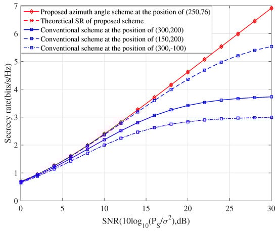
Figure 2.
The achievable SR performance versus SNR for our proposed azimuth angles scheme, where three typically random deployments are invoked as the baselines.
Figure 3 shows the attainable SR performance of our proposed pitch angles scheme versus the SNR. Similarly, the three conventionally random deployments are invoked for comparison. The results show that this proposed scheme is also superior to the conventionally random deployments. This also proves that the basic ideas of the two methods we proposed are completely correct. From Figure 2 and Figure 3, it is clear to find, no matter the azimuth angles scheme or pitch angles scheme we adopt, if only the deployed UAV satisfies the constraint of , the optimal secrecy rates can achieve by the optimal beamforming of .
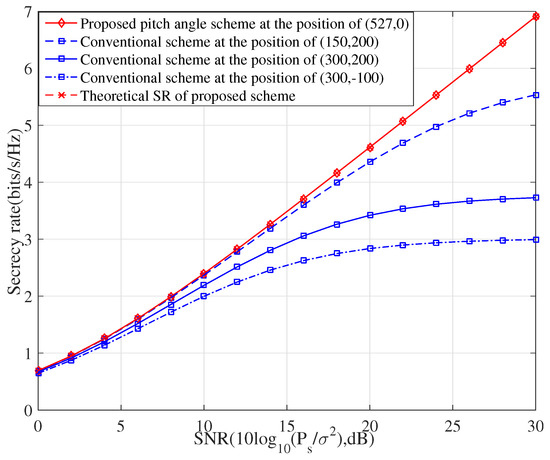
Figure 3.
The achievable SR performance versus SNR for our proposed pitch angle scheme, where three typically random deployments are invoked as the baselines.
To illustrate the efficiency of our proposed UAV-assisted SPWT scheme in gaining the security, Figure 4 shows that the achievable SR performance varies as increases. It can be noted that the SR performances of the three conventional comparison schemes are constantly unable to achieve the optimal SR performance even with the aid of power allocation. In fact, the SR performance of the conventional scheme seriously degrades when the UAV is randomly deployed. Hence, properly arranging UAV has a momentous impact on the SPWT. While for our proposed UAV deployment eliminating the AN signaling, it overleaps the power split operation but remains gaining the maximum SR performance, which further corroborates the potential value for the SPWT. Another interesting conclusion is that the SR of our proposed scheme remains the maximum value and unchanged, this means our proposed scheme do not need the artificial noise, this is because , regardless of the power of artificial noise, the received SNR at Eve is always 0. Thus, artificial noise is unnecessary, and this brings the benefit of a budget reduction.
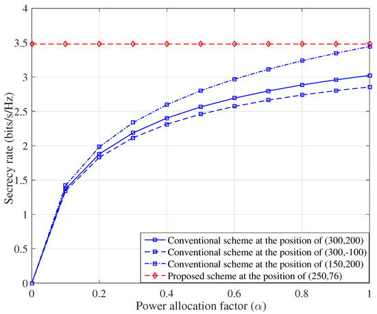
Figure 4.
The achievable SR performance versus parameter for the different scheme when SNR is 15 dB.
In summary, simulation results show that our proposed UAV deployment schemes achieve the SR enhanced SPWT compared with an UAV randomly distributed scheme. Moreover, the UAV transmit power is concentrated on transmitting confidential message but not part-allocated to AN. Thus, our proposed UAV deployment SPWT schemes are more secure and more energy efficiency.
4. Conclusions
In this letter, we proposed an UAV deployment scheme in the context of SPWT from the perspective of azimuth angle and pitch angle. In this scheme, we abandoned FDA for the first time and adopted the method of combining DM with 3D scenario, which reduces the system budget significantly. Compared to the conventional method, the proposed scheme is more superior in terms of the attainable SR performance. Moreover, our proposed UAV deployment algorithm gives the analytical solutions which has almost no complexity, this is also an important benefit of our proposed scheme. Interestingly, although we introduced AN in this hybrid SPWT system, the mathematic analysis shows that when the allocated power in AN is zero, the performance achieves the optimal, this means our proposed scheme do not need AN assistance to achieve the optimal SR performance, which has a powerful ability in economizing the precious energy resource.
Author Contributions
Conceptualization, T.S.; methodology, T.S.; software, L.G.; validation, X.Z., G.X. and F.S.; formal analysis, T.S.; investigation, T.S.; resources, G.X.; data curation, G.X.; writing—original draft preparation, T.S.; writing—review and editing, G.X. and J.Y.; visualization, F.S.; supervision, X.Z.; project administration, F.S.; funding acquisition, F.S. All authors have read and agreed to the published version of the manuscript.
Funding
This work was supported in part by the Scientific Research Fund Project of Anhui Agricultural University under Grant rc482106, Grant rc482103 and Grant rc482108, in part by National Natural Science Foundation of China under Grant 61901121, Grant 62001225, Grant 62071234, Grant 62071289, and Grant 61972093, in part by the Natural Science Research Project of Education Department of Anhui Province of China under Grant KJ2021A0183 and K2248004, in part by the Key Research and Development Project of Anhui Province in 2022(202204c06020022), in part by the Natural Science Foundation of Jiangsu Province under Grant BK20190454, in party by the open research fund of National Mobile Communications Research Laboratory, Southeast University under Grant 2022D07, in part by the Scientific Research Fund Project of Hainan University under Grant KYQD(ZR)-21007 and Grant KYQD(ZR)-21008, in part by the Hainan Major Projects under Grant ZDKJ20211022, and in part by the National Key R and D Program of China under Grant 2018YFB1801102.
Institutional Review Board Statement
Not applicable.
Informed Consent Statement
Not applicable.
Data Availability Statement
Not applicable.
Conflicts of Interest
The authors declare no conflict of interest.
Abbreviations
The following abbreviations are used in this manuscript:
| UAV | Unmanned Aerial Vehicle |
| SPWT | Secure Precise Wireless Transmissions |
| SR | Secrecy Rate |
| AN | Artificial Noise |
| DM | Directional Modulation |
| RF | Radio Frequency |
| FDA | Frequency Diverse Array |
| LoS | Line-of-Sight |
| 3D | Three-Dimensional |
References
- Wu, Y.; Khisti, A.; Xiao, C.; Caire, G.; Wong, K.-K.; Gao, X. A survey of physical layer security techniques for 5G wireless networks and challenges ahead. IEEE J. Sel. Areas Commun. 2018, 36, 679–695. [Google Scholar] [CrossRef]
- Chen, X.; Ng, D.W.K.; Gerstacker, W.H.; Chen, H.-H. A survey on multiple-antenna techniques for physical layer security. IEEE Commun. Surv. Tutor. 2017, 19, 1027–1053. [Google Scholar] [CrossRef]
- Bai, J.; Wang, H.-M.; Liu, P. Robust irs-aided secrecy transmission with location optimization. IEEE Trans. Commun. 2022, 70, 6149–6163. [Google Scholar] [CrossRef]
- Rao, H.; Xiao, S.; Yan, S.; Wang, J.; Tang, W. Optimal geometric solutions to uav-enabled covert communications in line-of-sight scenarios. IEEE Trans. Wirel. Commun. 2022, 21, 10633–10647. [Google Scholar] [CrossRef]
- Daly, M.P.; Bernhard, J.T. Directional modulation technique for phased arrays. IEEE Trans. Antennas Propag. 2009, 57, 2633–2640. [Google Scholar] [CrossRef]
- Yuan, D.; Fusco, V.F. Orthogonal vector approach for synthesis of multi-beam directional modulation transmitters. IEEE Trans. Antennas Wirel. Propagat. Lett. 2015, 14, 1330–1333. [Google Scholar]
- Jinsong, H.; Feng, S.; Jun, L. Robust synthesis method for secure directional modulation with imperfect direction angle. IEEE Commun. Lett. 2016, 20, 1084–1087. [Google Scholar]
- Sammartino, P.F.; Baker, C.J.; Griffiths, H.D. Frequency diverse MIMO techniques for radar. IEEE Trans. Aerosp. Electron. Syst. 2013, 49, 201–222. [Google Scholar] [CrossRef]
- Nusenu, S.Y.; Huaizong, S.; Ye, P. Power allocation and equivalent transmit fda beamspace for 5G mmwave noma networks: Meta-heuristic optimization approach. IEEE Trans. Veh. Technol. 2022, 71, 9635–9646. [Google Scholar] [CrossRef]
- Hu, Y.Q.; Chen, H.; Ji, S.-L.; Wang, W.-Q.; Chen, H. Adaptive detector for fda-based ambient backscatter communications. IEEE Trans. Wirel. Commun. 2022, 21, 10381–10392. [Google Scholar] [CrossRef]
- Wang, L.; Wang, W.-Q.; So, H.C. Covariance matrix estimation for fda-mimo adaptive transmit power allocation. IEEE Trans. Signal Process. 2022, 70, 3386–3399. [Google Scholar] [CrossRef]
- Shen, T.; Zhang, S.; Chen, R.; Wang, J.; Hu, J.; Shu, F.; Wang, J. Two Practical Random-Subcarrier-Selection Methods for Secure Precise Wireless Transmissions. IEEE Trans. Veh. Technol. 2019, 68, 9018–9028. [Google Scholar] [CrossRef]
- Shen, T.; Lin, Y.; Zou, J.; Wu, Y.; Shu, F.; Wang, J. Low-Complexity Leakage-Based Secure Precise Wireless Transmission with Hybrid Beamforming. IEEE Wirel. Commun. Lett. 2020, 9, 1687–1691. [Google Scholar] [CrossRef]
- Shu, F.; Wu, X.; Hu, J.; Li, J.; Chen, R.; Wang, J. Secure and precise wireless transmission for random-subcarrier-selection-based directional modulation transmit antenna array. IEEE J. Sel. Areas Commun. 2018, 36, 890–904. [Google Scholar] [CrossRef]
- Zhou, X.; Yan, S.; Hu, J.; Sun, J.; Li, J.; Shu, F. Joint optimization of a uav’s trajectory and transmit power for covert communications. IEEE Trans. Signal Process. 2019, 67, 4276–4290. [Google Scholar] [CrossRef]
- Wu, Q.; Zeng, Y.; Zhang, R. Joint trajectory and communication design for multi-uav enabled wireless networks. IEEE Trans. Wirel. Commun. 2018, 17, 2109–2121. [Google Scholar] [CrossRef]
- Yi, F.; Zhang, C.; Baek, S.; Rawashdeh, S.; Mohammadi, A. Autonomous Landing of a UAV on a Moving Platform Using Model Predictive Control. Drones 2018, 2, 34. [Google Scholar] [CrossRef]
- Ouamri, M.A.; Oteşteanu, M.-E.; Barb, G.; Gueguen, C. Coverage Analysis and Efficient Placement of Drone-BSs in 5G Networks. Eng. Proc. 2022, 14, 18. [Google Scholar] [CrossRef]
- Shen, A.; Luo, J.; Ning, J.; Li, Y.; Wang, Z.; Duo, B. Safeguarding UAV Networks against Active Eavesdropping: An Elevation Angle-Distance Trade-Off for Secrecy Enhancement. Drones 2023, 7, 109. [Google Scholar] [CrossRef]
- Zhou, X.; Yan, S.; Shu, F.; Chen, R.; Li, J. UAV-Enabled Covert Wireless Data Collection. IEEE J. Sel. Areas Commun. 2021, 39, 3348–3362. [Google Scholar] [CrossRef]
- Hu, J.; Wu, Y.; Chen, R.; Shu, F.; Wang, J. Optimal Detection of UAV’s Transmission with Beam Sweeping in Covert Wireless Networks. IEEE Trans. Veh. Technol. 2020, 69, 1080–1085. [Google Scholar] [CrossRef]
- Li, Y.; Shu, F.; Shi, B.; Cheng, X.; Song, Y.; Wang, J. Enhanced RSS-based UAV localization via trajectory and multi-base stations. IEEE Commun. Lett. 2021, 25, 1881–1885. [Google Scholar] [CrossRef]
- Cheng, X.; Shu, F.; Li, Y.; Zhuang, Z.; Wu, D.; Wang, J. Optimal Measurement of Drone Swarm in RSS-Based Passive Localization with Region Constraints. IEEE Open J. Veh. Technol. 2023, 4, 1–11. [Google Scholar] [CrossRef]
- Zhou, X.; Li, J.; Shu, F.; Wu, Q.; Wu, Y.; Chen, W.; Hanzo, L. Secure SWIPT for Directional Modulation-Aided AF Relaying Networks. IEEE J. Sel. Areas Commun. 2021, 37, 253–268. [Google Scholar] [CrossRef]
- Kraus, J.D.; Marhefka, R.J. Antennas For All Applications; McGraw-Hill, Inc.: New York, NY, USA, 2002. [Google Scholar]
Disclaimer/Publisher’s Note: The statements, opinions and data contained in all publications are solely those of the individual author(s) and contributor(s) and not of MDPI and/or the editor(s). MDPI and/or the editor(s) disclaim responsibility for any injury to people or property resulting from any ideas, methods, instructions or products referred to in the content. |
© 2023 by the authors. Licensee MDPI, Basel, Switzerland. This article is an open access article distributed under the terms and conditions of the Creative Commons Attribution (CC BY) license (https://creativecommons.org/licenses/by/4.0/).