Abstract
Electromagnetic shielding is an underutilized method for non-invasive proximity sensing that could be useful in automated production lines as a low-cost method to locate products. A strong relationship was shown between the position of a tag and individual sensors. The strength of the magnetic field generated by the coil was reduced by up to 25% when the tag was above the sensor and started to decay when the tag was within 15 mm of each sensor. These measurements can then be aggregated to provide a greater range of measurement.
1. Introduction
Many industrial workflows and processes are being streamlined by automating inspection tasks. One of the critical difficulties in these environments is finding a robust, practical, low-cost solution when sensing the location of objects on the production line.
Inductive sensors have been used as short-range proximity sensors, with a typical sensing range of less than 10 mm, or rely on permanent magnets [1]. However, this range is not suitable for inspection tasks. Alternatively, vision systems are often used, but these are high-cost and require large amounts of computer processing power. A novel sensing and localization solution uses an aluminum tag to shield a sensor from an electromagnetic field.
2. Materials and Methods
A test rig (Figure 1) was developed as a proof of concept using a coil that emitted an electromagnetic field that oscillated at 12.9 kHz, driven by a resonant current-fed push–pull inverter [2]. Briefly, 100 mm beneath the coil was a 3 × 4 array of DRV425 fluxgate magnetic-field sensors spaced 30 mm apart. A 30 × 30 × 3 mm tag was placed on a surface 30 mm above the sensing array.
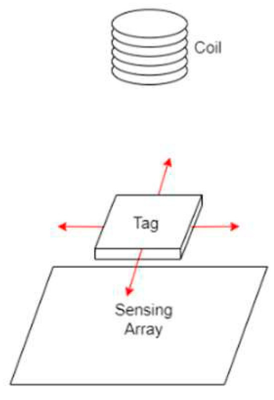
Figure 1.
Sensing system. The plane the tag moves on exists between the coil and the sensing array.
The tag was moved in 10 mm increments to determine the effect that the tag would have on the strength of the electromagnetic field. This effect was characterized as a proportion of the unshielded signal strength.
3. Discussion
A sensing array can capitalize upon the position-based relationship to determine where a metal tag is located in a 2D plane (Figure 2). As the aluminum tag moved over to the sensor, there was a proportional decrease in signal strength for each individual sensor. The signal strength started to decay 5 mm before the tag began to cover the sensor directly underneath the coil, ultimately reducing the signal strength by up to 75%, hence denoting the location of the tag (Figure 3).
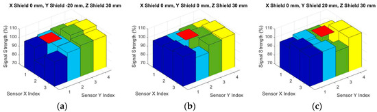
Figure 2.
Signal strength detected by ground plane sensors. The red square denotes the position of the 30 × 30 mm tag. The index represents the position of the sensor. Index (2, 2) is directly beneath the coil, and the spacing between sensors is 30 mm: (a) signal reading when the tag is at (0, −20, 30); (b) signal reading when the tag is at (0, 0, 30); (c) signal reading when the tag is at (0, 20, 30).
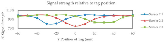
Figure 3.
The signal strength of sensors as a tag moves along the x-axis of the sensor array.
4. Conclusions
A novel method of proximity sensing has been proposed based upon electromagnetic shielding. There is a strong relationship between electromagnetic field strength and the position of a tag, with a reduction in signal strength of up to 75% due to magnetic field shielding when the tag is 30 mm above the sensing array. This relationship can be capitalized upon to locate a low-cost tag in an industrial environment.
Author Contributions
Conceptualization, K.M. and K.C.A.; methodology, K.M. and K.C.A.; software, K.M.; validation, K.M.; formal analysis, K.M.; investigation, K.M.; resources, K.C.A.; data curation, K.M.; writing—original draft preparation, K.M.; writing—review and editing, K.M. and K.C.A.; visualization, K.M.; supervision, K.C.A.; project administration, K.C.A.; funding acquisition, K.C.A. All authors have read and agreed to the published version of the manuscript.
Funding
This research was funded by Callaghan Innovation.
Institutional Review Board Statement
Not applicable.
Informed Consent Statement
Not applicable.
Data Availability Statement
The data are not publicly available.
Conflicts of Interest
The authors declare no conflicts of interest.
References
- Ripka, P.; Mirzaei, M.; Blazek, J. Magnetic position sensors. Meas. Sci. Technol. 2021, 33, 022002. [Google Scholar] [CrossRef]
- Abdolkhani, A.; Hu, A.P. Improved autonomous current-fed push–pull resonant inverter. IET Power Electron. 2014, 7, 2103–2110. [Google Scholar] [CrossRef]
Disclaimer/Publisher’s Note: The statements, opinions and data contained in all publications are solely those of the individual author(s) and contributor(s) and not of MDPI and/or the editor(s). MDPI and/or the editor(s) disclaim responsibility for any injury to people or property resulting from any ideas, methods, instructions or products referred to in the content. |
© 2024 by the authors. Licensee MDPI, Basel, Switzerland. This article is an open access article distributed under the terms and conditions of the Creative Commons Attribution (CC BY) license (https://creativecommons.org/licenses/by/4.0/).