Article

A Fractional-Order Sliding Mode DTC–SVM Framework for Precision Control of Surgical Robot Actuators

1
Department of Electrical Engineering, College of Engineering, Prince Sattam Bin Abdulaziz University, Al-Kharj 11942, Saudi Arabia
2
Control and Energy Management Laboratory (CEM-Lab), National Engineering School of Sfax, University of Sfax, Sfax 3038, Tunisia
*
Author to whom correspondence should be addressed.
Fractal Fract. 2026, 10(3), 193; https://doi.org/10.3390/fractalfract10030193
Submission received: 9 February 2026 / Revised: 5 March 2026 / Accepted: 10 March 2026 / Published: 13 March 2026
(This article belongs to the Special Issue Advanced Numerical Methods for Fractional Functional Models)

Abstract

Precise and smooth actuation is a central requirement in surgical robotics, where small tracking errors or oscillations can directly affect task quality and safety. This paper studies the control of an induction-motor-driven surgical joint using a sliding-mode strategy enhanced by fractional-order operators and implemented within a DTC–SVM structure. The motivation is to improve motion smoothness and disturbance rejection without sacrificing the fast dynamic response offered by direct torque control. A dynamic model of the actuator is developed by combining the electrical equations of the induction motor with the mechanical dynamics of a robotic joint, including inertia, viscous friction, gravity-induced torque, and Coulomb friction. Fractional-order sliding surfaces are introduced for both position and flux regulation, and the closed-loop stability is examined through Lyapunov-based arguments. Simulation results show accurate trajectory tracking with limited overshoot and smooth transient responses. The motor speed remains well regulated, while stator flux and currents stay within admissible bounds. The electromagnetic torque adapts to load variations with reduced ripple, and the rotor pulsation remains bounded. Within the limits of numerical evaluation, these results indicate that the proposed fractional-order sliding-mode DTC–SVM scheme is suitable for precision-oriented surgical robotic actuation.

1. Introduction

Medical robotics has gradually altered the way many surgical procedures are performed, especially in applications that require high-precision positioning and careful tool manipulation [1,2]. In such settings, the actuation units play a decisive role, as they must deliver precise torque and position responses while remaining in contact with the soft tissues and being exposed to varying interaction forces [3]. These practical constraints directly affect both the mechanical design of the actuators and the selection of convenient control strategies.
From a motor-drive perspective, induction motors (IMs) are often considered a practical solution due to their robustness, compact form, and moderate cost compared to brushed and permanent-magnet drives [4]. However, the nonlinear nature of the motor dynamics, combined with parameter variations and external perturbations, can degrade motion quality if they are not adequately compensated [5,6]. Achieving stable and smooth actuator motion under such conditions, therefore, remains challenging.
To address these issues, several nonlinear control approaches have been considered for IM-driven. Proportional–integral–derivative (PID) controllers and integer-order sliding mode control (SMC) are still widely used because of their simplicity and a certain degree of robustness. Their shortcomings become apparent when operating conditions deviate from nominal values, as uncertainties can lead to insufficient disturbance rejection, torque oscillations, and chattering, which are undesirable in delicate surgical tasks. These limitations have prompted interest in alternative control formulations that are better suited to uncertain environments [7].
From a control-theoretic viewpoint, fractional-order methods have attracted attention as a means of improving robustness and transient shaping. In particular, fractional-order sliding mode control (FOSMC) has been investigated to enhance control performance, as fractional differentiation provides an additional tuning degree of freedom. By introducing memory effects into the control law, this approach enhances robustness and adaptability while reducing the chattering typically observed with classical SMC schemes [8,9]. This property is particularly relevant for minimally invasive surgical procedures, where smooth actuator motion and well-shaped transients are required. Recent studies further suggest that FOSMC strategies retain the robustness of classical SMC while offering improved performance in the presence of uncertainties and disturbances [10].
Beyond methodological developments, FO and adaptive sliding mode control strategies have been reported in various robotic and electric-drive applications. Adaptive FOSMC has been applied to nonholonomic mobile robots, resulting in improved tracking accuracy and robustness under uncertain conditions [11]. In motor-drive applications, combining FOSMC with disturbance observation or compensation techniques has been shown to improve transient behavior and reduce torque and speed ripple when compared with conventional SMC and PI-based controllers [12]. These results underline the interest of fractional-order approaches for demanding electromechanical systems.
In robotic applications, and particularly in surgical robotics, fractional-order and sliding-mode strategies have been explored to improve precision and safety. FOSMC has been extended to multi-degree-of-freedom robotic manipulators, confirming the relevance of fractional-order formulations for high-precision and safety-critical robotic applications [13]. Comparative studies further indicate that FO control strategies can surpass conventional approaches in terms of tracking accuracy and robustness for nonlinear robotic platforms, which supports their relevance for surgical robotics [14].
A broader literature has examined fractional-order control from adaptive and PID-based viewpoints. In Ref. [15], a fractional model reference adaptive control scheme is proposed using incommensurate adaptation laws applied to both the plant and the reference model, with stability analyzed through frequency-distributed representations of fractional integrators. A related adaptive approach is presented in Refs. [16,17], where a fractional PID controller is applied to flotation processes in copper extraction via MRAC, although stability is not explicitly addressed. An overview of fractional-order controllers and their applications in robotics and power electronics is given in Ref. [18], highlighting the limitations of conventional PID schemes and the performance improvements obtained with fractional-order PID structures.
In Ref. [19], a FOSMC is developed for a fractional-order SEPIC converter, showing improved transient behavior compared with classical SMC. The impact of fractional-order operators in sliding mode schemes is further analyzed for the speed control of permanent magnet synchronous machines in Refs. [20,21], where improvements in tracking performance and robustness are reported. Parameter tuning strategies for integer- and fractional-order PID-type controllers are discussed in Ref. [22], although disturbance rejection is not the main focus of that study.
More elaborate control structures combine FOSMC with intelligent techniques. In Ref. [23], an adaptive fuzzy logic controller optimized for fractional-order sliding is proposed for nuclear reactor power regulation. FOSMC approaches have also been applied to nonlinear robotic manipulators. In particular, Ref. [24] studies a 3-DOF surgical robot subject to uncertainties by combining robust SMC, fractional-order PID, and fuzzy logic to reduce chattering. Similarly, Ref. [25] proposes a fuzzy-smoothing FOSMC for surgical robots and reports improved tracking performance compared with classical SMC for time-varying nonlinear trajectories. Related work in Ref. [26] applies FOSMC to robotic manipulators to limit energy losses and mechanical wear caused by chattering.
FOSMC has also been explored outside robotics, including epidemiological modeling [27], rehabilitation robotics [28], and aerospace systems affected by disturbances, actuator faults, and communication delays [29]. Taken together, these contributions highlight the ability of fractional-order and sliding mode techniques to improve robustness and tracking accuracy while reducing chattering. However, most existing studies remain application-specific or rely on complex hybrid designs, and systematic quantitative comparisons with classical SMC, as well as detailed sensitivity analyses of fractional-order parameters, remain limited and not clearly explained.
Motivated by the previous observations, this work proposes a comprehensive FOSMC–DTC–SVM control architecture for induction-motor-driven surgical robotic actuation. In fact, unlike existing FOSMC–DTC–SVM frameworks, which are mainly developed for speed control based on a second-order outer-loop model, the present study addresses position control using a third-order nonlinear dynamic system. Consequently, previously reported control laws cannot be directly applied, prompting the development of a novel FOSMC controller specifically designed to handle higher-order nonlinear position dynamics.
The proposed approach explicitly examines the role of the fractional-order term in the sliding surface, provides quantitative comparisons with classical integer-order SMC, and evaluates robustness under significant parameter perturbations.
The principal contributions of this study are summarized as follows:
  • A fractional-order sliding mode control formulation is developed for induction-motor-driven surgical actuators, where fractional-order operators are embedded on both the position and flux sliding surfaces to improve robustness, motion smoothness, and tracking accuracy under nonlinear dynamics and uncertainties.
  • The proposed strategy combines FO–SM control with a DTC–SVM scheme within a single structure, enabling torque and flux regulation while maintaining a fixed switching frequency. This design helps to limit chattering and promotes smoother actuator motion, which is important in safety-critical surgical applications.
  • The proposed approach is assessed by comparing it with classical integer-order sliding mode control under identical conditions. Variations in load torque and rotor resistance are considered.
This paper is organized as follows: Section 2 describes the dynamic model of the IM and its mechanical coupling with a surgical robotic joint, including the main physical effects relevant to medical actuation. Section 3 demonstrates the proposed control strategy based on fractional-order sliding mode control combined with DTC–SVM. The simulation results and their discussion are presented in Section 4. The paper ends with concluding remarks and perspectives for future work.

2. Surgical Robotic Actuation System

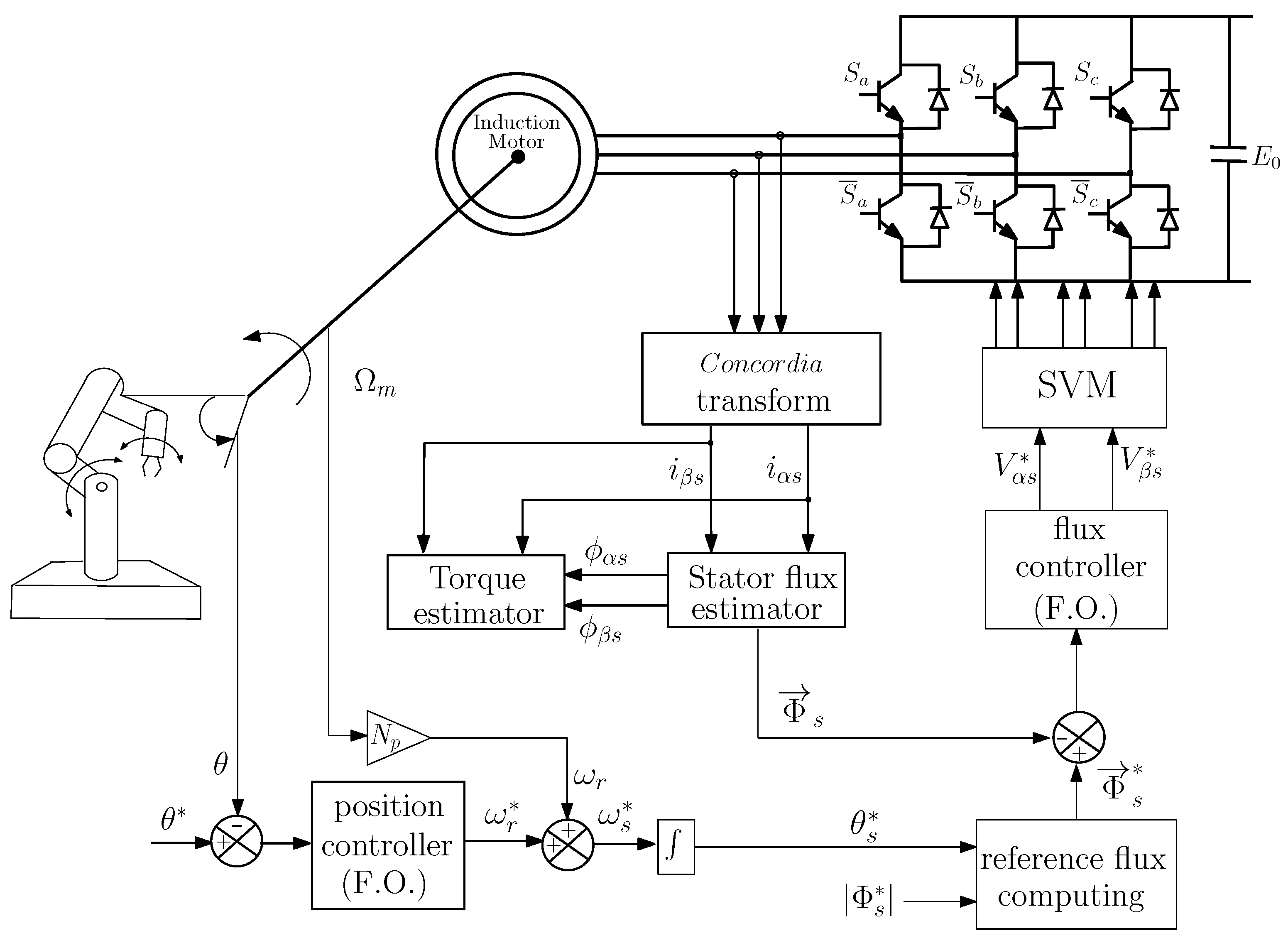
Figure 1 illustrates the global control structure of the fractional-order DTC–SVM strategy applied to an induction-motor-driven surgical actuator. The proposed architecture relies on a fractional-order position controller in the outer loop, while torque and flux are regulated in the inner loops through a DTC–SVM scheme. Stator flux and electromagnetic torque are estimated online to directly select the inverter switching states, while preserving a fixed switching frequency. The introduction of fractional-order terms introduces memory effects that enhance robustness against modeling inaccuracies and load disturbances commonly encountered during surgical manipulation.
More precisely, the outer-loop fractional-order position controller converts the position tracking error into a reference speed command, which is then fed to the inner DTC–SVM loops. These inner loops control the electromagnetic torque and stator flux based on real-time measurements of stator currents and rotor speed, ensuring fast transient behavior and bounded electrical variables. The resulting voltage reference vectors are applied to the inverter through the SVM block, producing the corresponding switching signals. This hierarchical control structure assumes standard sensor availability and real-time computation and reflects a practical, implementable architecture for induction-motor-driven surgical robotic actuation.

2.1. Notations

For x = x 1 x 2 R 2 :
sign x = sign x 1 sign x 2 , | x | = | x 1 | | x 2 | , | x | γ = | x 1 | γ | x 2 | γ , | x | γ sign x = | x 1 | γ sign x 1 | x 2 | γ sign x 2
and:
| | x | | 1 = | x 1 | + | x 2 | , | x | γ 1 = | x 1 | γ + | x 2 | γ

2.2. Induction Machine with DTC-SVM Design

The dynamic model of induction motors can be described using space variables as follows [30,31]:
d d t ϕ α s = R s i α s + v α s d d t ϕ β s = R s i β s + v β s d d t ϕ α r = N p Ω m ϕ β r R r i α r d d t ϕ β r = N p Ω m ϕ α r R r i β r
The subscripts r and s correspond to the rotor and stator, respectively, while α and β denote the components in the ( α , β ) reference frame. The symbols ϕ , i, and v stand for flux, current, and voltage, respectively. The parameters R r and R s represent the rotor and stator resistances, and Ω m denotes the mechanical speed of the machine, which is linked to the slip speed through the relation ω s ω r = N p Ω m , where N p is the number of pole pairs.
The relationships between currents and fluxes are:
ϕ α s = s i α s + r s i α r ϕ α r = s r i α s + r i α r ϕ β r = s r i β s + r i β r ϕ β s = s i β s + r s i β r
Using s and r for the stator and rotor inductances, and r s = s r for the mutual inductances.
The electromagnetic torque can be represented by the following equation:
T e = N p ( ϕ α s i β s ϕ β s i α s )
The DTC-SVM block diagram retains the main benefits of the traditional DTC method, including the elimination of coordinate transformations and the achievement of rapid torque and flux control. A Space Vector Modulation (SVM) block generates pulses for the inverter, guaranteeing a consistent commutation frequency [32].

2.3. Mechanical Dynamics

The actuation subsystem of a surgical robot often relies on a high-precision induction motor (IM) coupled with a harmonic drive reducer. The mechanical behavior of this actuator can be represented by the following equations:
J m d Ω m d t + B m Ω m = T e T L ,
d θ m d t = Ω m ,
where J m and B m denote the inertia of the rotor and the viscous friction coefficient, respectively. The variables T e , T L , Ω m , and θ m correspond to electromagnetic torque, load torque, angular speed, and angular position of the motor shaft.

2.4. Load Torque Model for Surgical Applications

In the context of surgical robotics, the actuator drives a lightweight, compliant manipulator via a high-ratio gear transmission. The total load torque acting on the motor shaft can be expressed as
T L ( Ω m , Ω ˙ m , θ m ) = J e q Ω ˙ m + B e q Ω m + k g sin ( θ m ) + k f sign Ω m ,
where J e q and B e q represent the equivalent inertia and viscous friction referred to the motor side, while k g and k f denote the gravitational and Coulomb friction coefficients, respectively.
This formulation follows classical rigid-link robotic modeling approaches widely used for electric actuator–robot interactions, where gravitational, viscous, and Coulomb friction effects are included to capture dominant mechanical phenomena in joint-level dynamics [33,34]. Similar load torque representations have also been adopted in simulation-based studies of surgical and medical robotic actuators [35,36].

2.5. Representative System Parameters

A typical surgical joint actuator can be characterized by the following parameters:
  • Gear ratio: G = 100 (harmonic drive)
  • Link mass and length: m = 0.8 kg, L = 0.25 m, center of mass L c = 0.12 m
  • Gravitational acceleration: g = 9.81 m/s2
  • Link inertia: J link = m L 2 3 1.67 × 10 2 kg·m2
  • Reflected link inertia: J link , m = J link G 2 = 1.67 × 10 6 kg·m2
  • Motor inertia: J m = 1.2 × 10 4 kg·m2
  • Equivalent inertia: J = 1.22 × 10 4 kg·m2
  • Equivalent damping: B e q = 1.0 × 10 3 N·m·s/rad
  • Coulomb friction: k f = 2.0 × 10 2 N·m
  • Gravitational torque: k g = m g L c G 9.42 × 10 3 N·m
The above numerical values are selected as representative parameters commonly reported for lightweight robotic joints and surgical manipulators equipped with high-ratio transmissions. They are not intended to correspond to a specific commercial system, but rather to provide a realistic and reproducible simulation environment for controller evaluation, as adopted in related robotic control studies [33,34].

2.6. Numerical Expression

By substituting the above values into (8), the load torque becomes:
T L ( θ m , Ω m , Ω ˙ m ) = 3.02 × 10 4 Ω ˙ m + 3.0 × 10 3 Ω m + 9.42 × 10 3 sin θ m + 2.0 × 10 2 sign Ω m .

2.7. Complete Dynamic Model

The final form of the motor-side dynamics is:
J d Ω m d t = T e T
with:
T = f ( θ m , Ω m ) = B e q Ω m + k g sin θ m + k f sign ( Ω m )
where the parameters J, B e q , k g , and k f take the numerical values listed above.
Although the present study focuses on simulation-based evaluation, experimental identification and validation of load parameters on real surgical robotic hardware constitute an important direction for future work. Such validation would further refine the parameter values and enable assessment of the model’s accuracy under physical interaction conditions.

3. Proposed Fractional SM Controller

3.1. Background on Fractional Computing

Several formal definitions of fractional-order differentiation are available in the literature, including the Riemann–Liouville, Grünwald–Letnikov, and Caputo formulations, which are widely used in theory and applications [37,38,39].
In this study, the Caputo definition is adopted to express the fractional-order derivative and integral of a function g ( t ) for orders σ ( 0 , 1 ) :
D t σ g ( t ) = 1 Γ ( σ ) 0 t ( t v ) σ 1 g ( v ) d v
D t σ g ( t ) = D t 1 D t ( 1 σ ) g ( t )
= d d t 1 Γ ( 1 σ ) 0 t ( t v ) σ g ( v ) d v = 1 Γ ( 1 σ ) 0 t ( t v ) σ d g d v d v
with the Γ function:
Γ ( η ) = 0 t η 1 e t d t
Consider a fractional-order Caputo system [37]:
D t σ X ( t ) = F ( t , X ( t ) )
where F : [ 0 , [ × V R n is piecewise continuous in t, V R n is a domain containing the equilibrium point X = 0 , [ F ( t , 0 ) = 0 ] , and σ ] 0 , 1 ] .
  • Using Lyapunov theory, the asymptotic stability for system (16) is provided as follows:
Theorem 1
([37]). For the nonautonomous fractional-order system described by Equation (16), where X = 0 represents the equilibrium point, we assume the existence of a Lyapunov function V ( t , X ( t ) ) which is positive definite satisfying the following condition:
D t σ V ( t , X ( t ) ) γ X ( t )
where σ ] 0 , 1 ] . Then, system (16) is locally asymptotically stable around X = 0 .
Lemma 1.
Let F ( t ) R n be a continuous function and Q a positive matrix of order n. Then for all t 0 :
D t σ F T ( t ) Q F ( t ) 2 F ( t ) T Q D t σ F ( t ) , σ [ 0 , 1 ]

3.2. Angular Position Control

The angular position is described by the following equations in DTC control:
d θ m d t = Ω m J d Ω m d t = T e T τ d T e d t + T e = A ω r
This gives:
θ m = Ω ¨ m = 1 J ( T ˙ e T ˙ ) = 1 J τ ( A ω r T e ) 1 J ( B e q Ω ˙ m + k g θ ˙ m cos θ m ) = 1 J τ ( A ω r T e ) 1 J B e q J ( T e T ) + k g Ω m cos θ m
Then:
θ m + B e q J 2 ( T e T ) + 1 J τ T e + k g J Ω m cos θ m = A J τ ω r
Let us consider θ d the desired position of the motor, and the following errors:
e = θ m θ d
ε = e ˙ + a 1 e
with the sliding function defined as follows:
s = ε ˙ + a 2 ε + a 3 D t σ ε
a 1 , a 2 and a 3 are positive scalars, and 0 < σ < 1 .
The control law is expressed in such a way that we have:
s ˙ = ( λ 1 + λ 3 | s | γ ) sign s λ 2 s
where λ 1 , λ 2 and λ 3 are positive scalars and 0 < γ < 1 .
Since we have:
e + ( a 1 + a 2 ) e ¨ + a 1 a 2 e ˙ + a 3 D t σ ε = ( λ 1 + λ 3 | s | γ ) sign s λ 2 s
this gives
ω r = τ A [ 1 τ T e + B e q J ( T e T ) + k g θ m ˙ cos θ m + J θ m d ( a 1 + a 2 ) e ¨ a 1 a 2 e ˙ a 3 D t 1 σ e ˙ + a 1 e ( λ 1 + λ 3 | s | γ ) sign s λ 2 s ]
Theorem 2.
The control law defined by Equation (27) ensures that the angular position error e defined in Equation (22) goes to 0 asymptotically.
Proof. 
Now, let us define the following sliding function:
V 1 ( s ) = 1 2 s 2
Its differential with respect to time is:
d V 1 d t = s s ˙ = ( λ 1 | s | + λ 3 | s | γ + 1 ) λ 2 s 2 < 0
This ensures that the sliding function s approaches zero as time t increases.
Now, we should demonstrate that when the system reaches the sliding surface s = 0 and remains on it, the error converges to zero, thereby affirming the system’s good tracking. For that, we can write:
D t σ s = 0
thus:
ε ˙ + a 2 ε + a 3 D t σ ε = 0
and:
D t σ ε ˙ + a 2 ε = a 3 ε
Let us define the second Lyapunov function:
V 2 ( ε , ε ˙ ) = 1 2 a 3 ε 2 + 1 2 D t ( 1 σ ) ε ˙ + a 2 ε 2
Its time derivatives:
V ˙ 2 ( ε , ε ˙ ) a 3 ε ε ˙ + ε ˙ + a 2 ε D t σ [ ε ˙ + a 2 ε = a 3 ε ] = a 2 a 3 ε 2 0
This shows that ε converges to 0.
When ε = 0 , we have:
e ˙ = a 1 e
Consider a third Lyapunov equation:
V 3 ( e ) = 1 2 e 2 > 0
Its time derivative:
V ˙ 3 ( e ) = e ˙ e = a 1 e 2 = 2 a 1 V 3 ( e ) < 0
This shows an exponential stability and an exponential convergence to 0 of the error e. □

3.3. Flux Control

The flux vector Φ s is controlled by the stator voltage vector V s and is described by the following differential equation:
d Φ d t = V s R s I s
Let us define the sliding function [40]:
s ϕ = e ϕ + a 0 D t σ e ϕ
where a 0 > 0 , e ϕ = Φ Φ d and e ˙ ϕ = Φ ˙ Φ ˙ d = Φ ˙ . σ belongs to ] 0 , 1 [ . The desired trajectory is defined by: Φ d = 1Wb and Φ ˙ d = 0 .
The goal is to determine the adequate control, assuming that:
s ˙ ϕ = [ ( μ 1 + μ 3 | s ϕ | γ ) sign s ϕ + μ 2 s ϕ ]
μ 1 > 0 and μ 2 > 0 . This results:
e ˙ ϕ + a 0 D t 1 σ e ϕ = ( μ 1 ϕ sign s ϕ + μ 2 ϕ s ϕ )
Then:
V s = R s I s + Φ ˙ d a 0 D t 1 σ e ϕ [ ( μ 1 + μ 3 | s ϕ | γ ) sign s ϕ + μ 2 s ϕ ]
where μ 1 , μ 2 and μ 3 are positive scalars and 0 < γ < 1 .
This result guarantees that the system state reaches the sliding surface s ϕ = 0 .
Theorem 3.
Consider the system denoted by (38) and the suggested sliding function (39). The control law guarantees the asymptotic stability of the closed-loop system (42).
Proof. 
First, we should demonstrate that the system’s trajectory reaches the sliding surface s ϕ = 0 . For this, we should demonstrate that the norm of s ϕ is a strictly decreasing function of time. Then, we consider the subsequent Lyapunov function:
V 4 ( s ϕ ) = 1 2 s ϕ T s ϕ
Its time derivatives are:
V ˙ 4 ( s ϕ ) = s ϕ T s ˙ ϕ = μ 1 ϕ | | s ϕ | | 1 μ 3 ϕ | s ϕ | γ + 1 1 μ 2 ϕ s ϕ T s ϕ < 0
When the system remains at the surface s ϕ = 0 , we can write D t σ s ϕ = 0 , so:
D t σ e ϕ = a 0 e ϕ
To ensure that the trajectory error converges to zero, let us consider the Lyapunov function:
V 5 ( e ϕ ) = 1 2 e ϕ T e ϕ
Its time fractional derivatives are given by:
D t σ V 5 ( e ϕ ) e ϕ T D t σ e ϕ = a 0 e ϕ T e ϕ < 0
Then, the system converges to its desired flux trajectory with asymptotic stability. □

4. Simulation Results and Discussion

4.1. Comparison with Existing Control Strategies

The proposed fractional-order sliding mode DTC–SVM controller is quantitatively compared with commonly used control strategies for induction motor-driven robotic systems. Conventional PI-based DTC–SVM schemes exhibit increased torque ripple and slower dynamic response under load variations, while integer-order sliding mode control improves robustness at the expense of chattering effects [41,42,43,44]. Fractional-order controllers help alleviate these shortcomings by introducing memory effects that improve motion smoothness and transient response [7].
The simulation parameters expressed in SI are: a 1 = a 2 = 10 , a 3 = 90.79 , λ 1 = 200 , λ 2 = 400 , λ 3 = 40 , a 0 = 20 , μ 1 = 50 , μ 2 = 100 , μ 3 = 20 , and σ = 0.5 .

4.2. Discussion on a 3

Let us discuss the parameter a 3 of the sliding function s in Equation (24). First, we have defined ε in terms of the error e (Equation (23)). When ϵ = 0 , the dynamical behavior of the error is described by the following characteristic equation:
p + a 1 = 0
where p is the Laplace operator. The error e converges to 0 with the dynamical behavior of e a 1 t . However, when the sliding function s becomes 0, the dynamical behavior of ε is described by the following characteristic equation (Equation (24)):
p + a 2 + a 3 p σ = 0
In our case, we have chosen σ = 0.5 . The solution of the last equation is complex and can be written as:
p = r e j θ
r > 0 and π 2 < θ π . In this case, the dynamical behavior of the system is equivalent to a second order with a damping factor z = cos θ and a non damping pulsation ω n = r . This gives the following equations:
r cos θ + a 2 + a 3 r cos θ 2 = 0
r sin θ a 3 r sin θ 2 = 0
This gives the following relations:
r = a 2 1 + 2 cos θ
a 3 = 2 r r cos θ 2
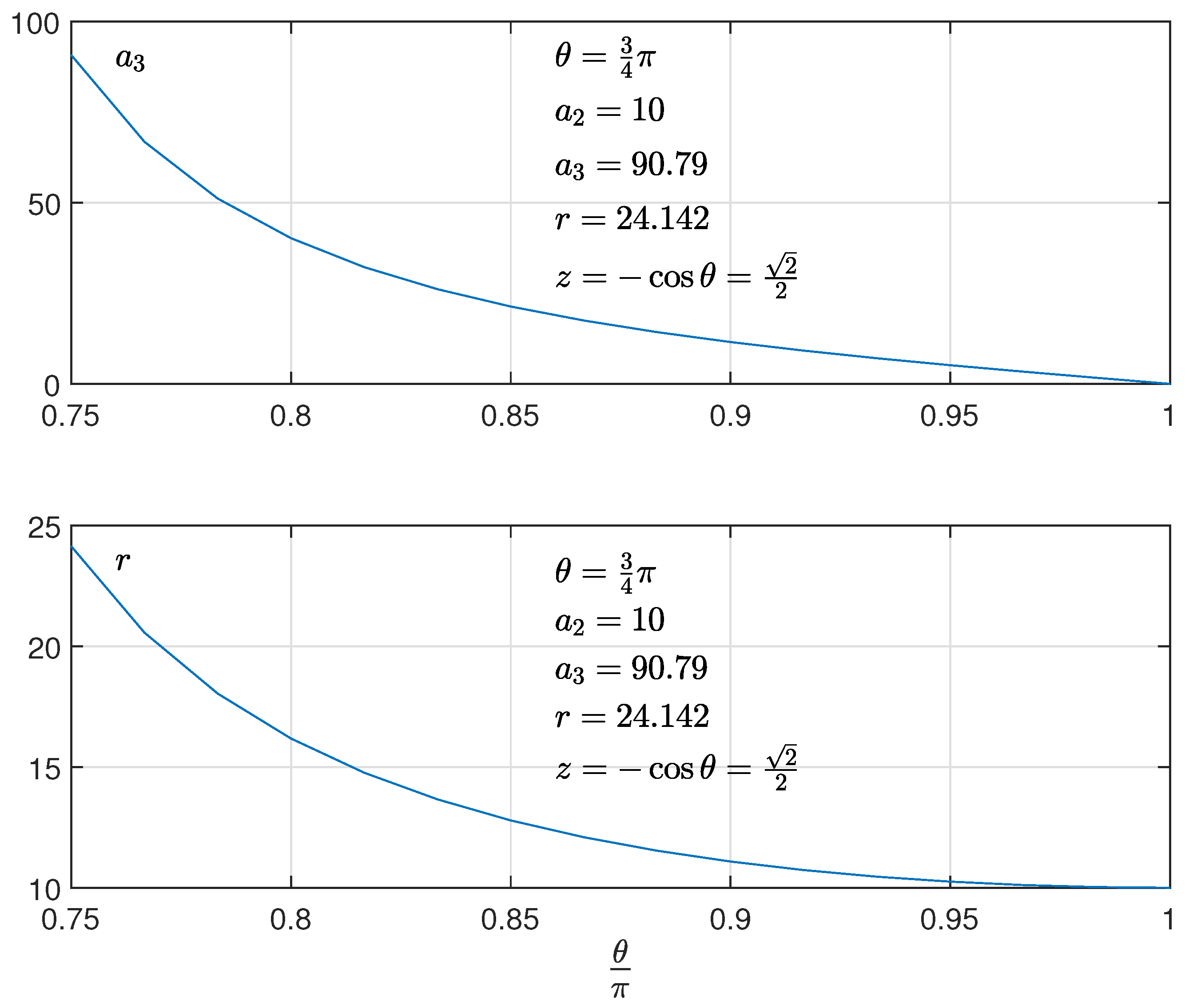
Figure 2 presents the evolution of the parameter a 3 in terms of the argument of the complex root of Equation (49), as well as the evolution of its non damping pulsation.
In order to have good performances, the damping factor should be: z = cos θ 1 2 , that is 3 π 4 θ π . However, for z = 1 2 , the torque present high pick. For that, we choose a 3 = 20 , giving a damping factor z = 0.9782 and an acceptable pick of the torque.
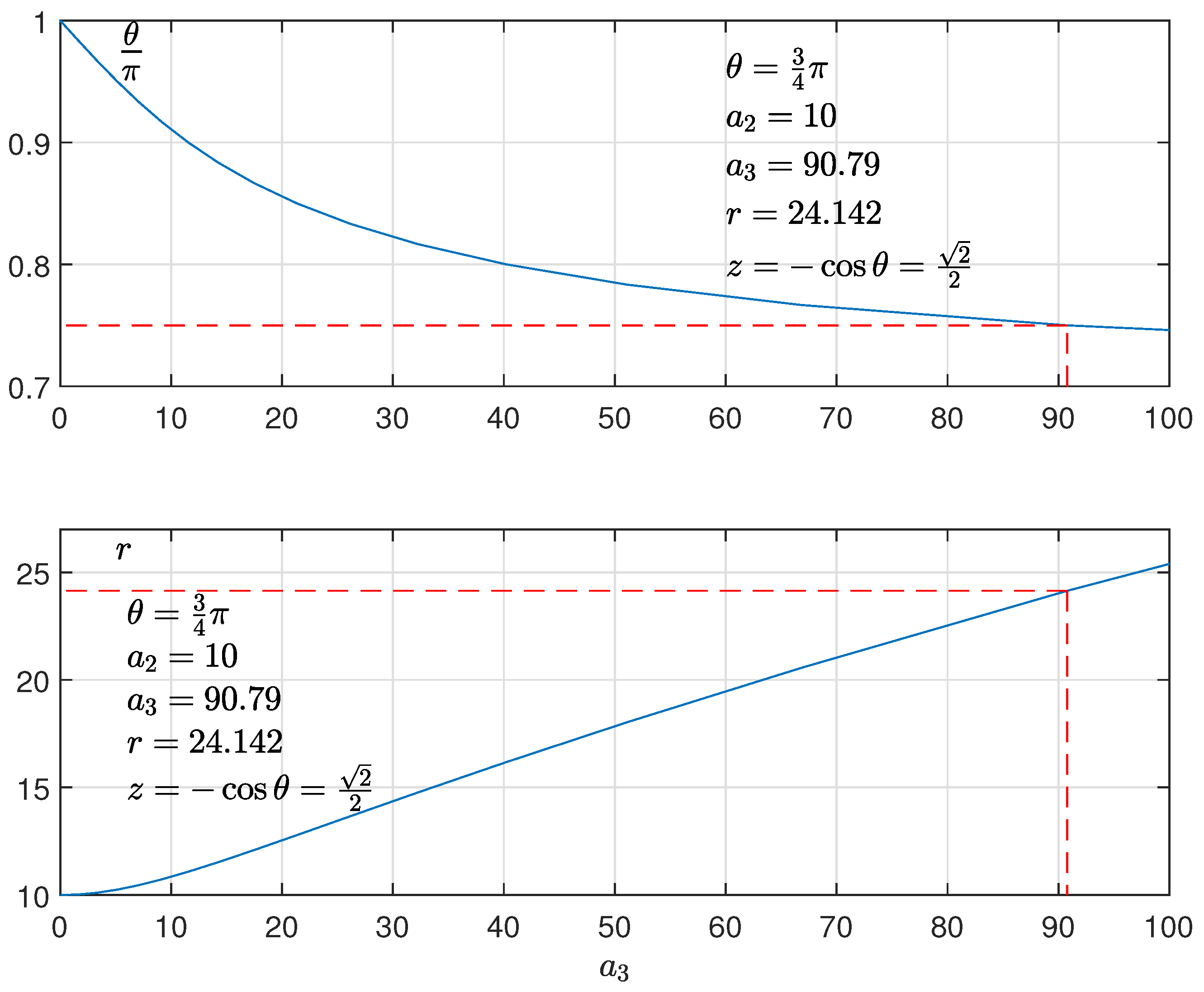
Figure 3 presents the evolution of the parameter θ as well as the evolution of the non damping pulsation in terms of the gain a 3 . The best case consists of choosing θ = 3 π 4 as shown in this figure in dashed lines.
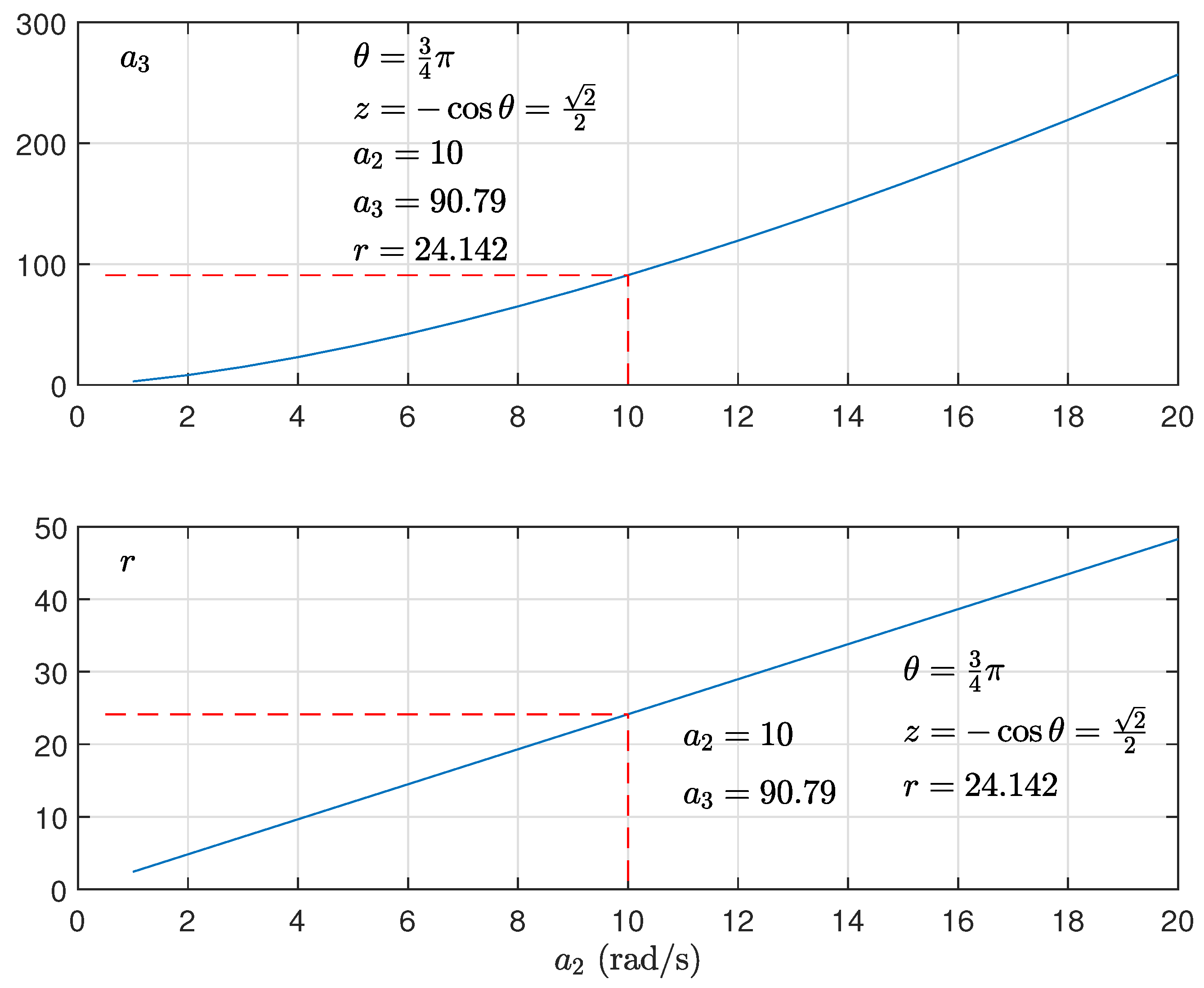
Figure 4 presents the evolution of the parameter a 3 as well as the evolution of the non damping pulsation in terms of the gain a 2 , for the best case θ = 3 π 4 . The best values of a 3 and r for a 2 = 10 are shown in this figure in dashed lines.

4.3. Obtained Results

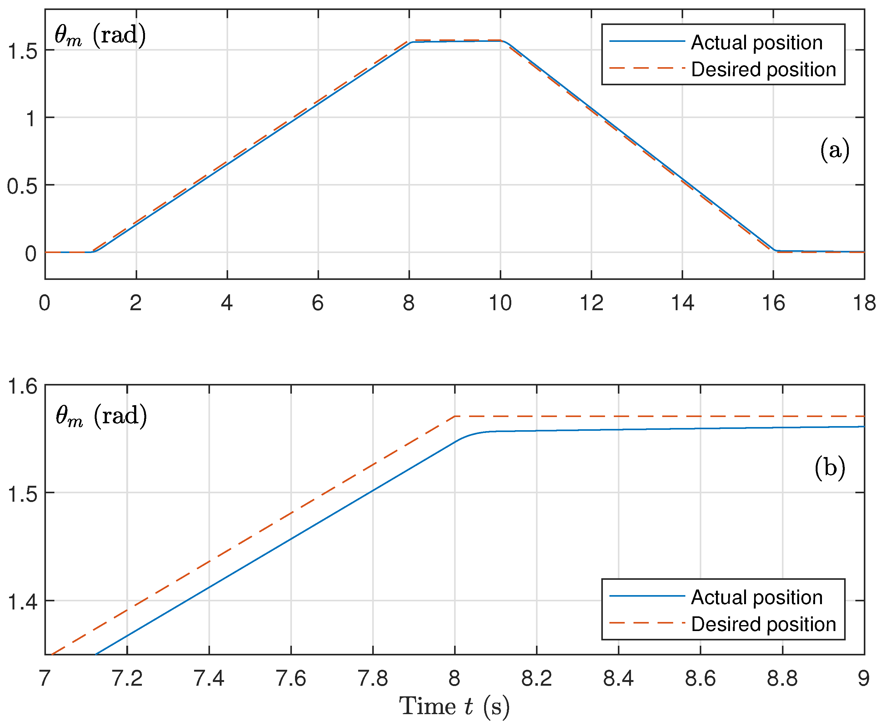
Figure 5 shows the response to the actuator angular position. The measured motor position θ m closely follows the reference trajectory θ d over the entire simulation horizon. The transition phases are smooth, and the steady-state error is negligible, reflecting the effectiveness of the proposed position control for precision-oriented surgical operations.
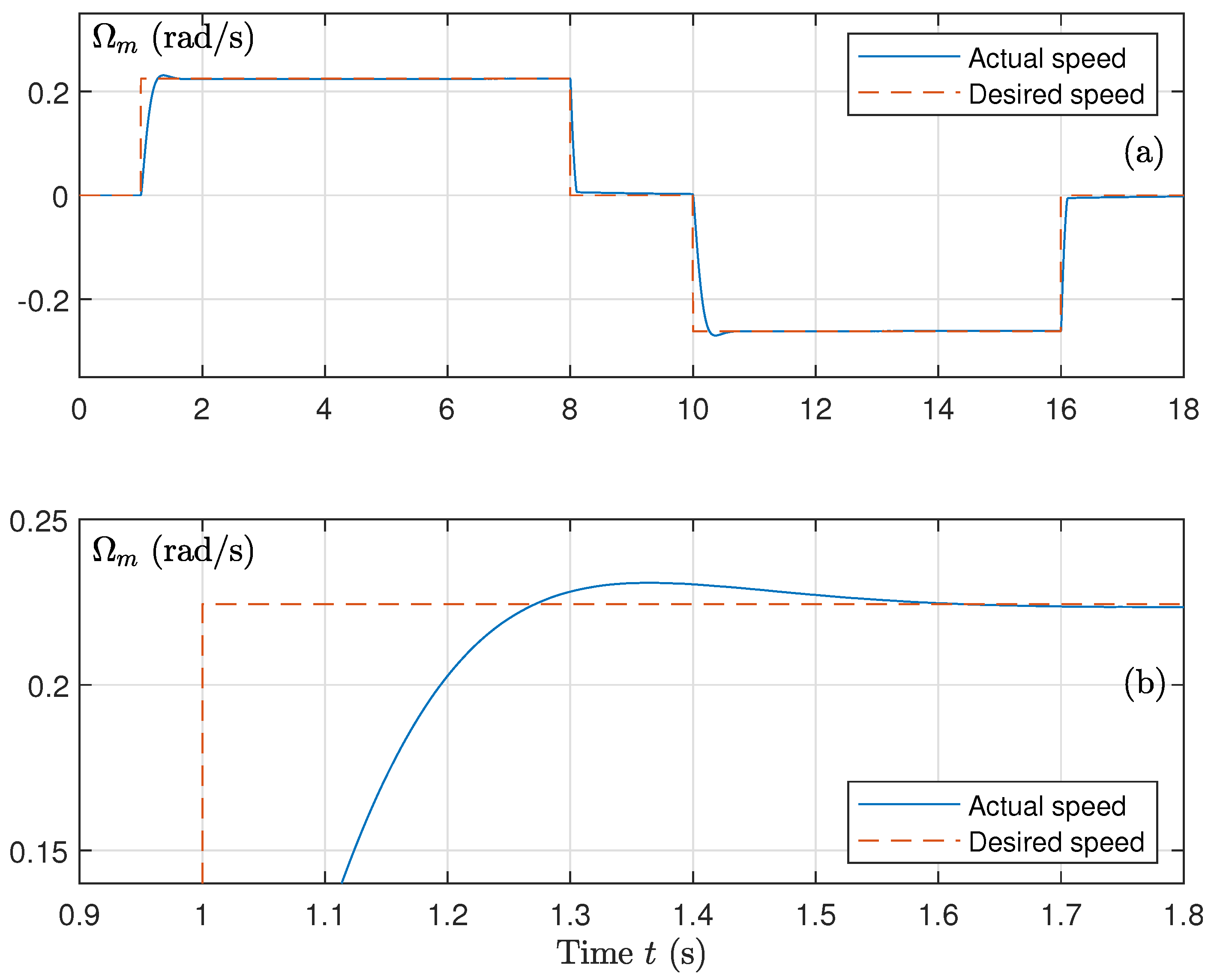
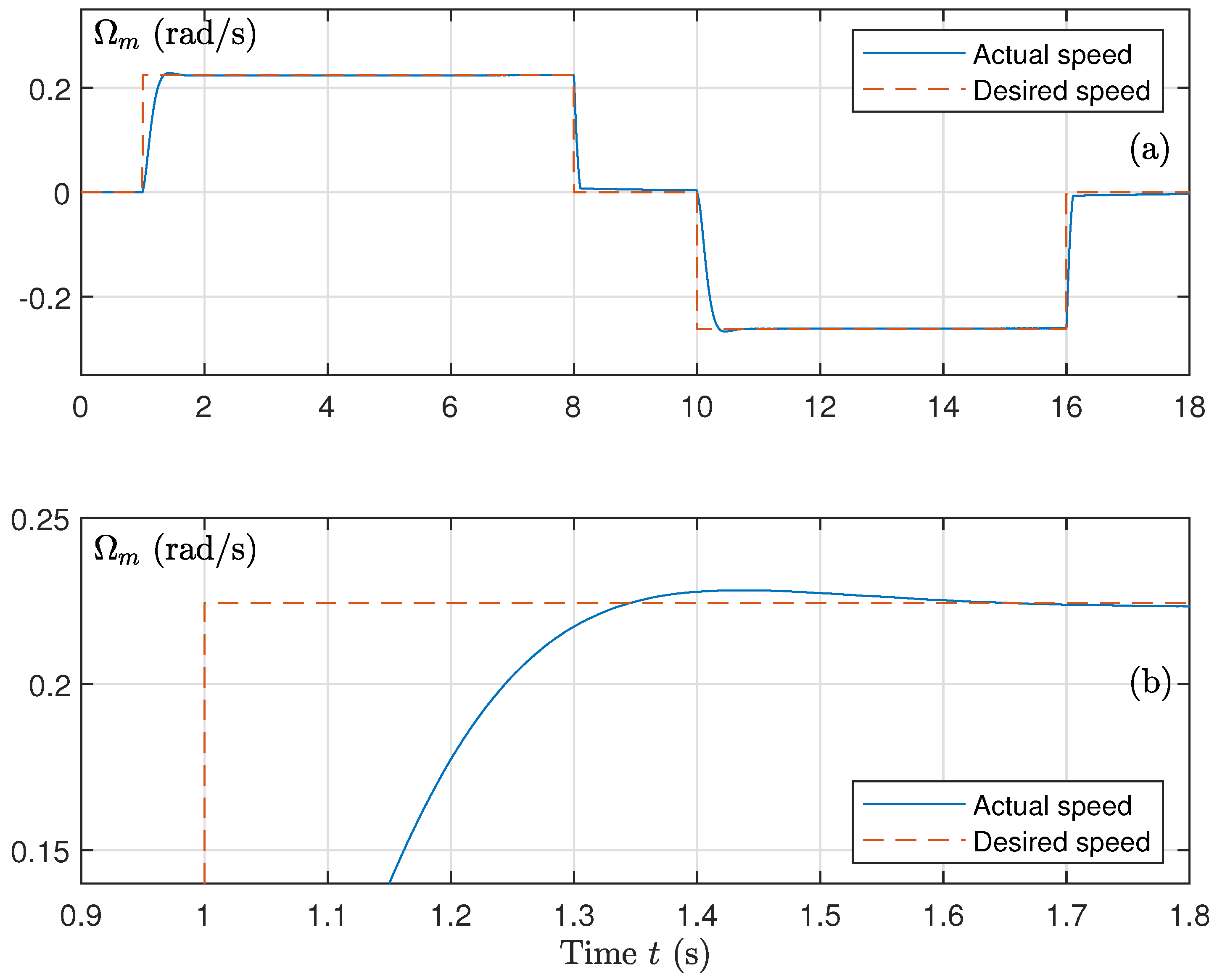
The associated angular speed response is presented in Figure 6. The motor speed closely follows the reference command, with smooth acceleration and deceleration phases. The absence of sharp transient peaks helps limit mechanical stress on the actuator.
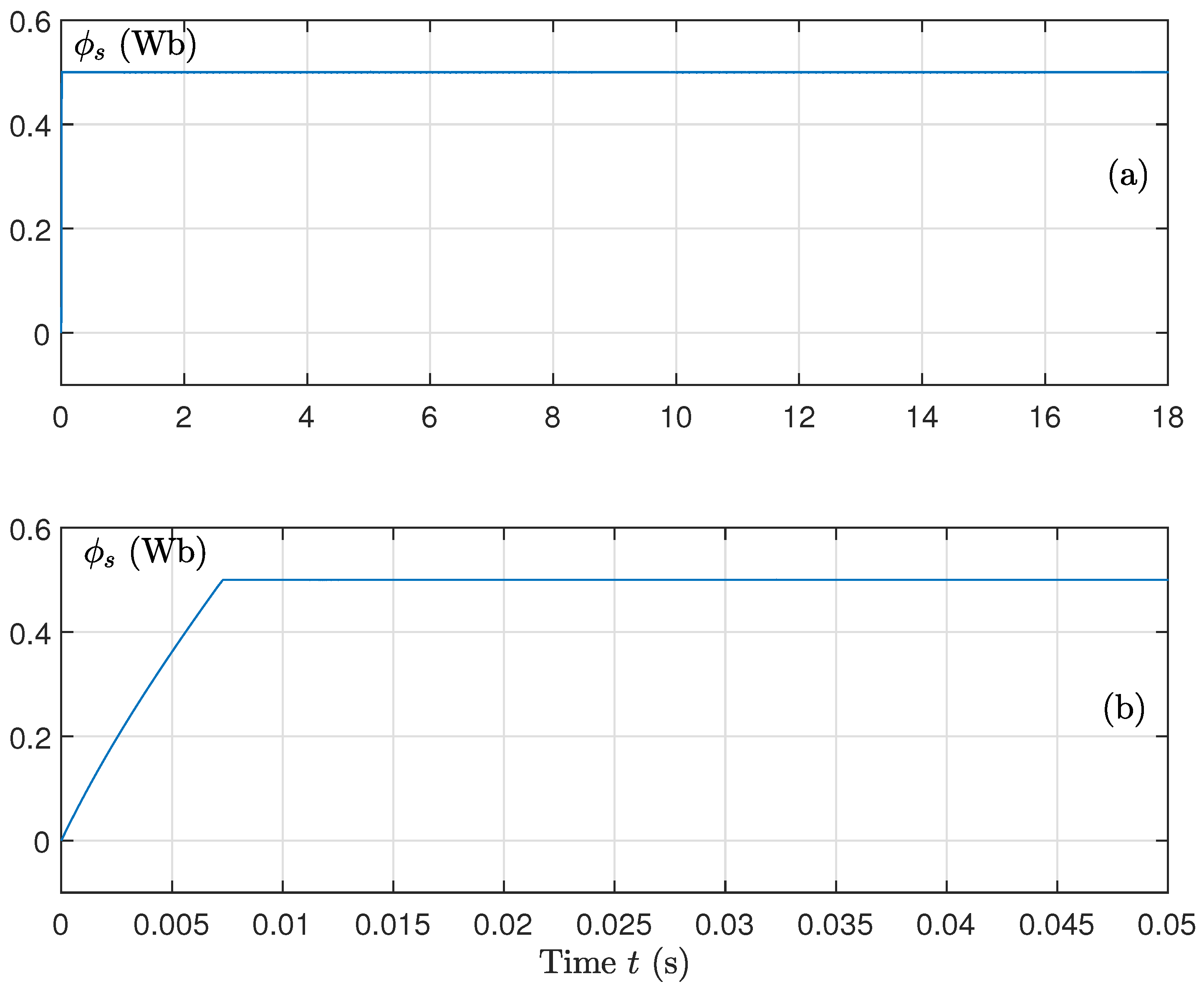
Figure 7 shows the evolution of the magnitude of the stator flux. Following a short transient phase, the flux converges to its reference and remains tightly regulated over the operating interval, indicating stable, robust behavior of the flux control loop. In particular, the desired flux level is reached after approximately 6.3 ms.
This fast convergence is promoted by including the nonlinear term μ 3 | s ϕ | γ sign ( s ϕ ) in the expression of s ˙ ϕ , as defined in (40). The presence of this term enforces finite-time convergence of the sliding variable, as discussed in [38,45].
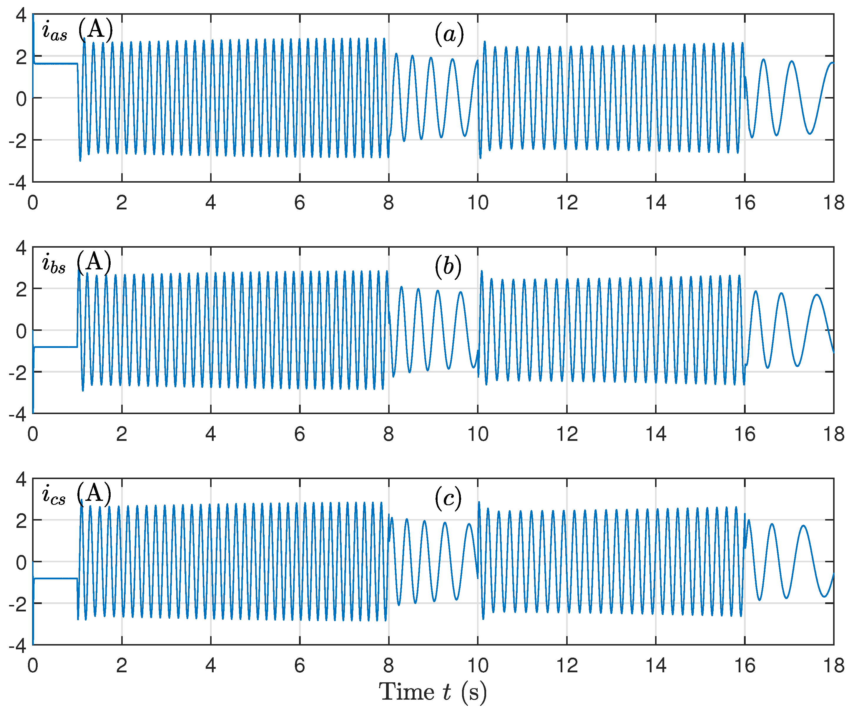
The stator current waveforms are shown in Figure 8. The three-phase currents remain well balanced and nearly sinusoidal, indicating stable electromagnetic operation and efficient power use.
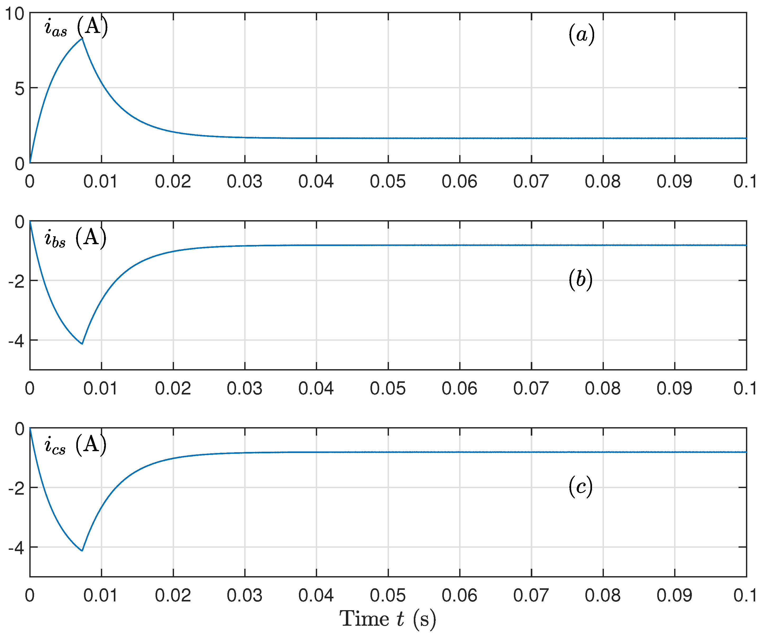
Figure 9 illustrates the transient behavior of the stator currents during the establishment of the flux. During this phase, the amplitudes of i a s , i b s , and i c s increase as the flux builds up and reach their maximum values when the desired flux level is attained at approximately 6.3 ms. Once the flux is settled, the current amplitudes decrease and converge to their steady-state waveforms.
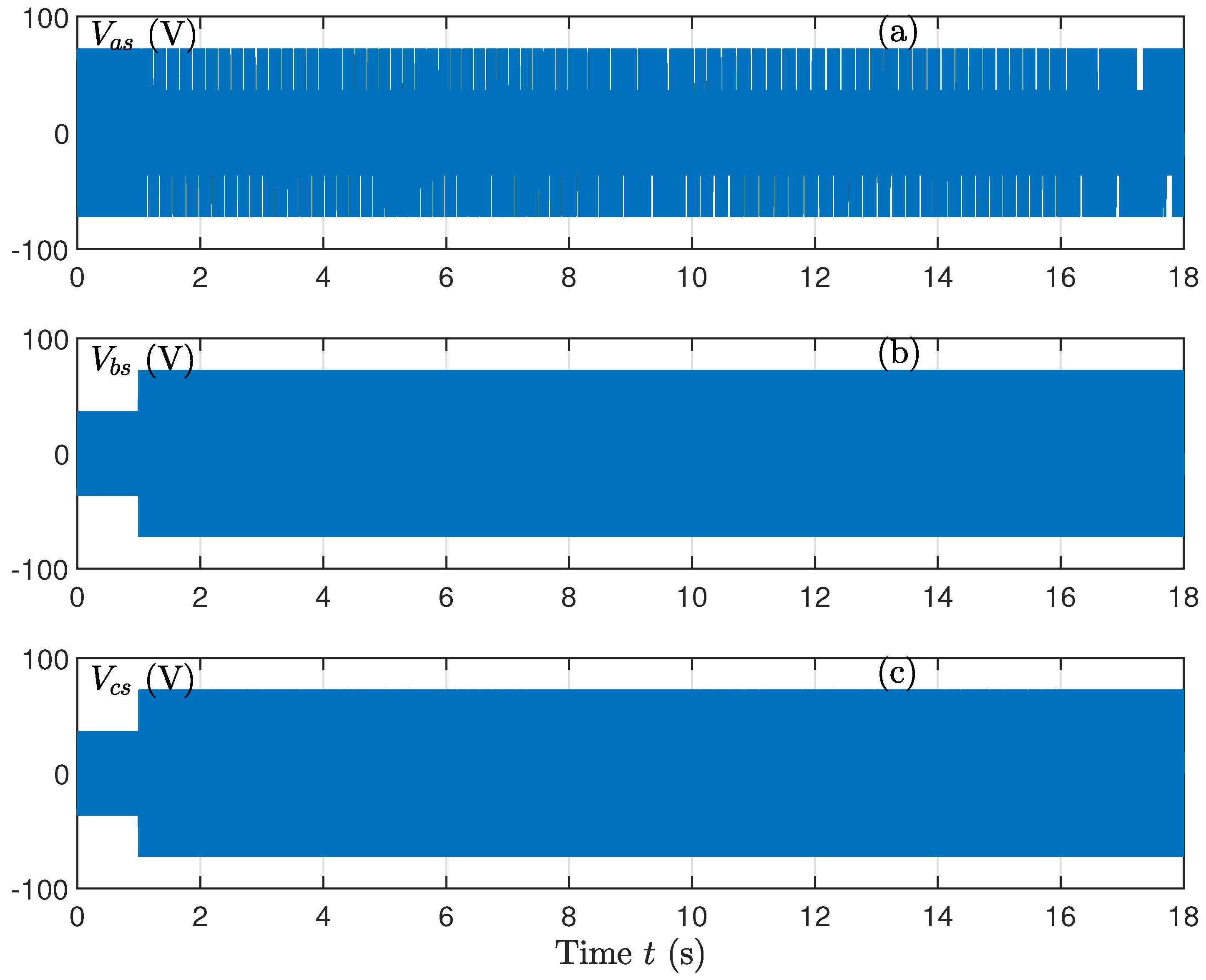
Figure 10 presents the stator voltages produced by the SVM inverter. The voltage waveforms exhibit regular switching behavior and remain within their nominal limits, confirming stable and reliable inverter operation under the proposed control approach.
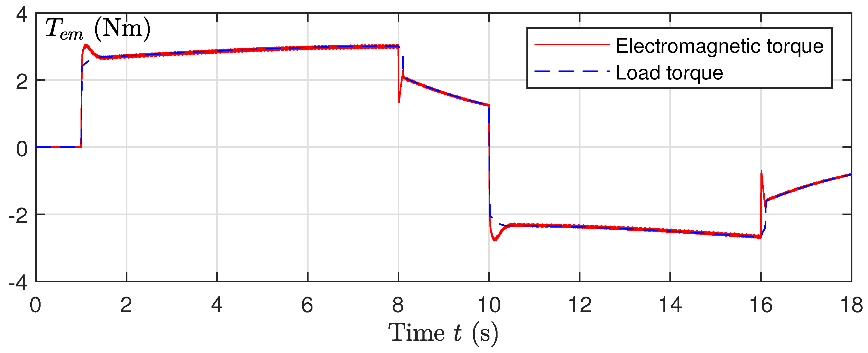
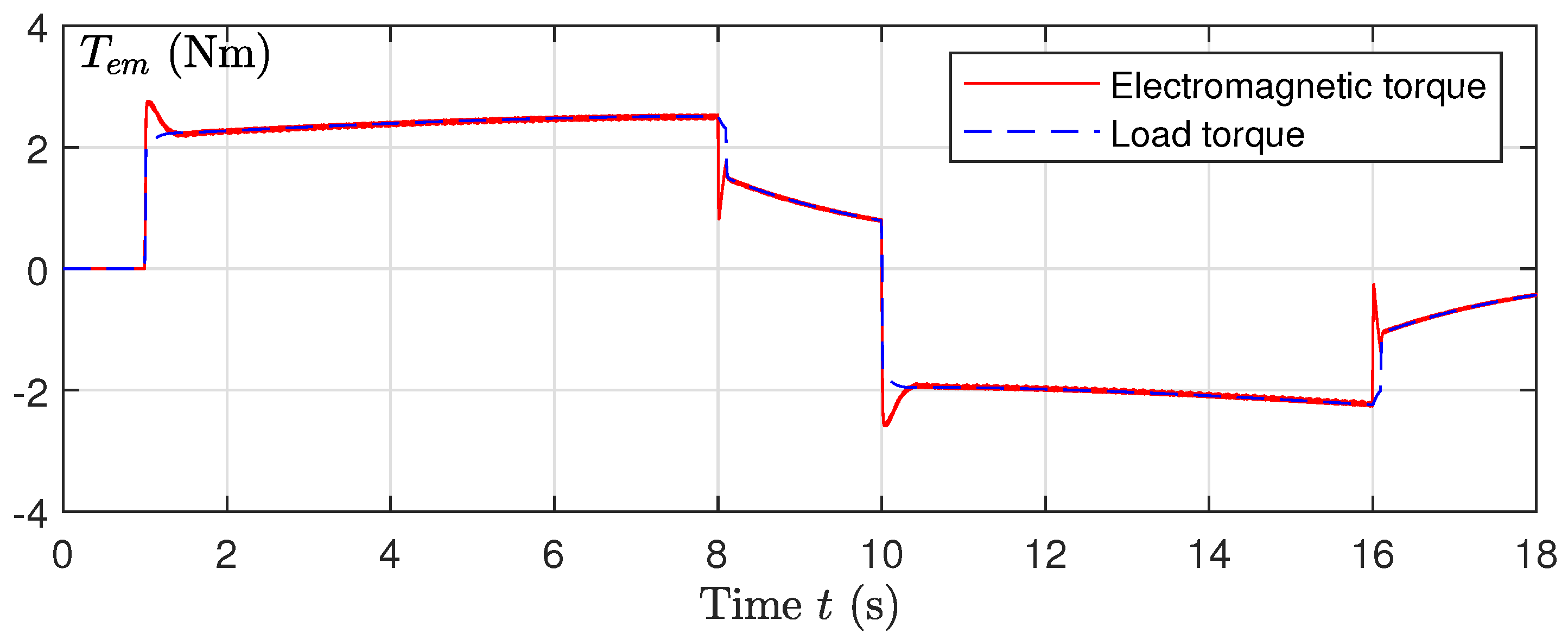
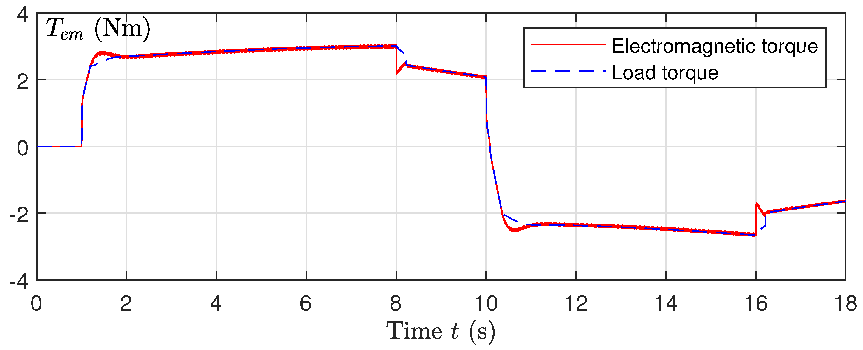
The electromagnetic and load torque profiles are presented in Figure 11. The electromagnetic torque adapts smoothly to load torque variations, maintaining consistent force transmission with minimal ripple. This contributes to smooth mechanical motion and reduced wear during robot surgical system actuation.
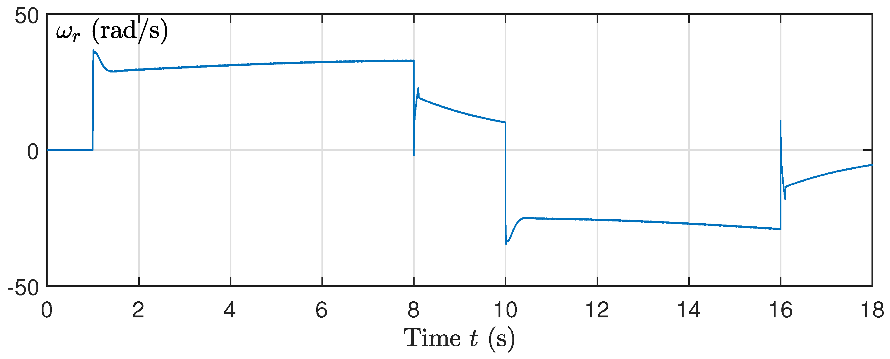
Finally, Figure 12 illustrates the rotor pulsation over the simulation interval. The signal remains bounded and exhibits stable behavior throughout the operating range, which reflects the robustness of the inner control loops and the overall reliability of the system.
The picks presented in the curves of the electromagnetic torque (Figure 11) and the rotor pulsation (Figure 12) are caused by sudden variations of the desired speed.
To complement the qualitative time-domain observations, key performance indices were computed from the simulation results and are reported in Table 1. These metrics provide a quantitative evaluation of tracking accuracy, transient behavior, and signal boundedness under the proposed control scheme.
The simulation outcomes suggest reduced oscillatory behavior and smoother torque profiles when compared with classical integer-order sliding mode control schemes commonly reported in the literature [45]. In particular, bounded rotor pulsation and limited torque ripple Suggest improved motion continuity, which is essential for surgical robotic applications.
In order to check the robustness of the proposed controller, we have applied + 20 % to the load torque and + 50 % to the resistance of the rotor caused by heating.
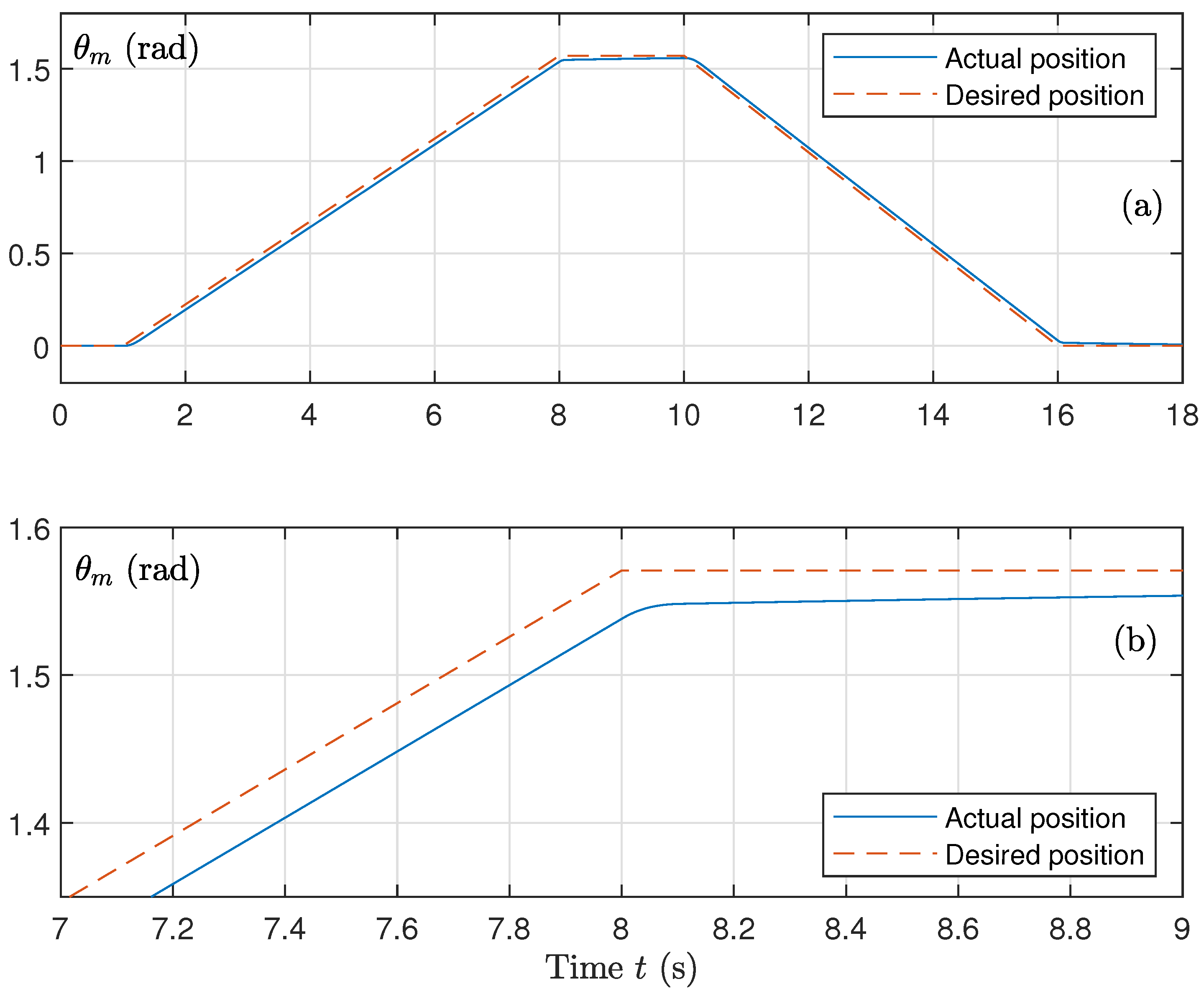
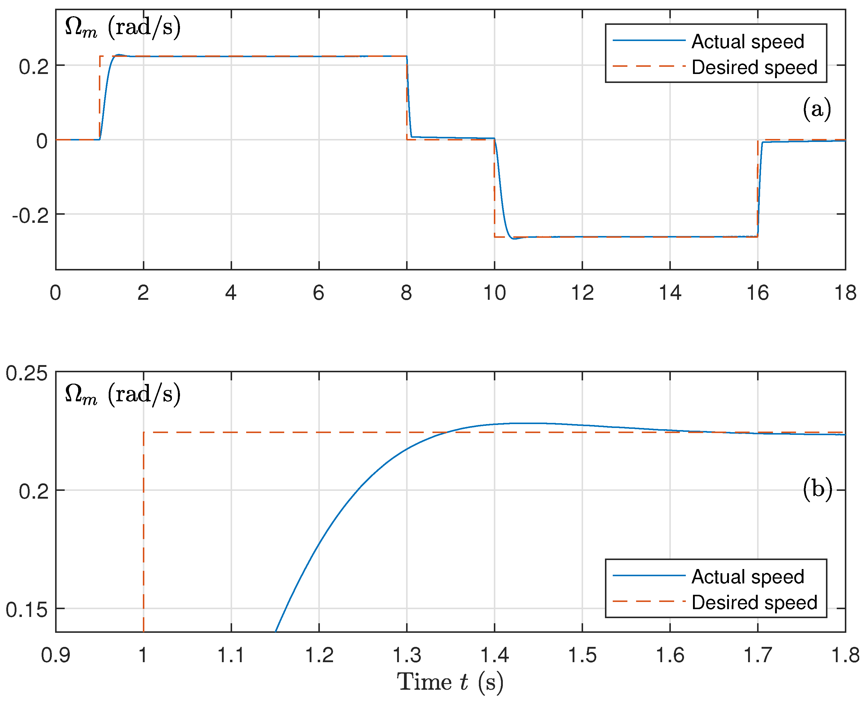
The results obtained are presented in Figure 13, Figure 14 and Figure 15. It is clear that the system follows its desired trajectory (Figure 13a and Figure 14a) with slightly slower dynamics (Figure 13b and Figure 14b). This is caused by an increase in the torque load. Moreover, the torque becomes 1.2 times larger compared to the unperturbed case (Figure 15). The rest of the variables (flux, currents, voltages, etc.) are insensitive to these perturbations.
The classical sliding function for the position control is defined as Equation (24) for which a 2 > 0 and a 3 = 0 . In previous papers [40,45], it has been shown that for a 3 > 0 , the dynamical behavior and the performances of the systems become better than in the case where a 3 = 0 . The same remark can be given for the sliding function for the flux control (Equation (39)). For the classical approach, we have a 0 = 0 . This causes oscillations in the flux. In fact, the flux oscillates around its desired value. In previous references, several authors have added an integral of the error. In this paper, we have considered a fractional integral of the flux error in order to obtain better performances, as shown in previous papers [40,45].
In order to show the improvements given by the introduction of the fractional order term a 3 D t σ ε present in the expression of the sliding surface s in Equation (24) for the angular position control θ m , we have considered the perturbation described above ( + 20 % on the load torque and + 50 % on the rotor resistance), and we have varied the parameter a 3 from a 3 = 0 (classical sliding mode control) to a 3 = 10 4 . We have defined the following numerical indices, (for T = 18 s the simulation horizon):
The Integral of the Absolute error on the position ( I A E θ ) and on the speed ( I A E Ω ), expressed in (°) and (°/s), respectively:
I A E θ = 1 T 0 T | θ m θ d | d t
I A E Ω = 1 T 0 T | Ω m Ω d | d t
The Integral of Squared error on the position ( I S E θ ) and on the speed ( I S E Ω ), expressed in (°) and (°/s), respectively:
I S E θ = 1 T 0 T | θ m θ d | 2 d t
I S E Ω = 1 T 0 T | Ω m Ω d | 2 d t
The maximum value M x ω and the minimum value M n ω of the control ω r , expressed in ( rad / s ).
The maximum value M x T and the minimum value M n T of the electromagnetic torque T e m , expressed in (Nm).
Table 2 and Table 3 show the importance of the fractional order term for reducing all error criteria on the angular position and on the angular speed. The classical case is represented by a 3 = 0 . For small values of the fractional parameter a 3 , results are similar to the classical case. High values of a 3 decrease these criteria. However, the size of the control ω r increases slightly. This is because this term acts on the sliding function s.
In order to compare the proposed Fractional-Order Sliding Mode DTC–SVM Framework with previous methods such as the Sliding Mode DTC–SVM approach, Figure 16, Figure 17 and Figure 18 present the obtained results using the Sliding Mode DTC–SVM classical approach.
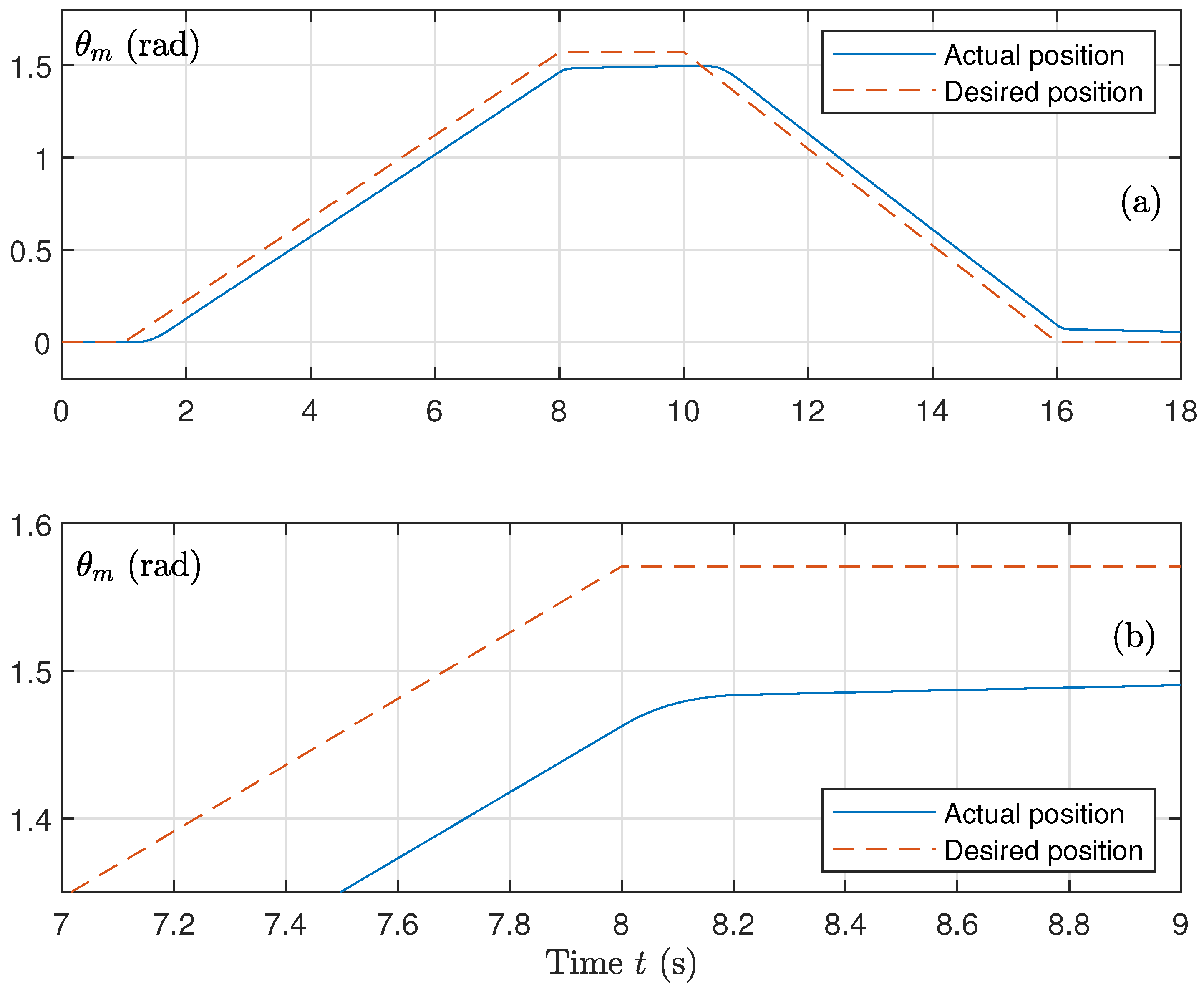
Figure 16, Figure 17 and Figure 18 present the evolution of the angular position θ m , the angular speed Ω m and the torque T e m , in the perturbed case: + 50 % on the stator resistance and + 20 % on the load torque. It is clear that results are sensitive to these perturbations. To avoid such sensitivity, three conditions should be realized:
  • Parameters a 1 and a 2 should be increased, yielding an increase in the control ω r and a significant increase in the peak of the electromagnetic torque.
  • The sudden variations of the desired speed should be avoided, as it is recommended in the literature.
  • An adaptive approach estimating the stator resistance and the load torque parameters can solve this problem.

5. Conclusions

This paper investigated a fractional-order sliding-mode control strategy integrated with a direct torque control and space-vector modulation framework for induction-motor-driven surgical robotic actuators. A comprehensive dynamic model was formulated to represent both the electrical characteristics of the induction motor and the mechanical behavior of a robotic joint, including the effects of inertia, friction, and gravity-related load relevant to medical applications.
The proposed control structure combined the robustness of the sliding mode control with the additional tuning flexibility introduced by fractional-order operators. The stability of the position and flux regulation loops was examined using Lyapunov arguments, which support the expected closed-loop behavior from a theoretical standpoint.
The simulation results show that the actuator follows the prescribed motion with good accuracy and without abrupt transitions. The angular speed remains properly regulated, and the stator flux, currents, and voltages stay within acceptable bounds during operation. The electromagnetic torque adapts to changes in the load with limited ripple, while the rotor pulsation remains bounded, indicating stable operation of the inner control loops.
Taken together, these observations suggest that the proposed FOSMC–DTC–SVM approach provides a practical control solution that improves motion smoothness, robustness, and tracking precision, which are important in safety-critical surgical robotic actuation. However, the present study is limited to simulation-based validation and experimental testing is required to fully assess the practical feasibility and real-time performance of the proposed control strategy. Future work will focus on implementing and validating solutions using hardware-in-the-loop platforms and experimental test benches that involve real induction motor drives and robotic joints operating under physical interaction conditions. It is also important to acknowledge certain limitations of the proposed approach. The use of fractional-order operators may increase computational complexity and require careful tuning.

Author Contributions

Methodology, F.B.S., J.M. and N.D.; Software, F.B.S., J.M. and N.D.; Validation, F.B.S., J.M. and N.D.; Formal analysis, F.B.S., J.M. and N.D.; Investigation, F.B.S.;Writing—original draft, F.B.S. and N.D.;Writing—review & editing, F.B.S., J.M. and N.D.; Supervision, J.M. and N.D.; Project administration, J.M.; Funding acquisition, J.M. All authors have read and agreed to the published version of the manuscript.

Funding

This research was funded by Prince Sattam Bin Abdulaziz University grant number PSAU/2025/01/5289.

Data Availability Statement

The raw data supporting the conclusions of this article will be made available by the authors on request.

Acknowledgments

The authors extend their appreciation to Prince Sattam bin Abdulaziz University for funding this research work through the project number (PSAU/2025/01/5289).

Conflicts of Interest

The authors declare no conflicts of interest.

Nomenclature

SymbolDescriptionUnit
a 0 , a 1 , a 2 , a 3 Sliding surface design parameters
AMotor constant in torque dynamics
B m Motor viscous friction coefficientN·m·s/rad
B e q Equivalent viscous damping coefficientN·m·s/rad
D t σ Fractional derivative of order σ
D t σ Fractional integral of order σ
ePosition tracking error ( θ m θ d )rad
e ϕ Flux tracking errorWb
GGear ratio
gGravitational accelerationm/s2
i α s , i β s Stator current componentsA
i α r , i β r Rotor current componentsA
J m Motor inertiakg·m2
JEquivalent inertia of actuatorkg·m2
k f Coulomb friction coefficientN·m
k g Gravitational torque coefficientN·m
l s Stator inductanceH
l r Rotor inductanceH
l r s Mutual inductanceH
m l Link masskg
N p Number of pole pairs
R s Stator resistance Ω
R r Rotor resistance Ω
sSliding surface for position control
s ϕ Sliding surface for flux control
T e Electromagnetic torqueN·m
T L Load torqueN·m
v α s , v β s Stator voltage componentsV
V s Stator voltage vectorV
Φ s Stator flux vectorWb
ϕ α s , ϕ β s Stator flux componentsWb
ϕ α r , ϕ β r Rotor flux componentsWb
Φ d Desired stator fluxWb
θ m Motor angular positionrad
θ d Desired angular positionrad
Ω m Mechanical angular speedrad/s
ω r Rotor electrical speedrad/s
ω s Stator electrical frequencyrad/s
λ 1 , λ 2 , λ 3 Position controller gains
μ 1 , μ 2 , μ 3 Flux controller gains
γ Nonlinear sliding gain exponent
σ Fractional differentiation order

References

  1. Taylor, R.H.; Menciassi, A.; Fichtinger, G.; Fiorini, P.; Dario, P. Medical robotics and computer- integrated surgery. IEEE Trans. Robot. Autom. 2008, 19, 765–781. [Google Scholar] [CrossRef] [Scilit]
  2. Yang, G.-Z.; Cambias, J.; Cleary, K.; Daimler, E.; Drake, J.; Dupont, P.E.; Hata, N.; Kazanzides, P.; Martel, S.; Patel, R.V.; et al. Medical robotics—Regulatory, ethical, and legal considerations for increasing levels of autonomy. Sci. Robot. 2017, 2, eaam8638. [Google Scholar] [CrossRef] [Scilit]
  3. Okamura, A.M. Haptic feedback in robot-assisted minimally invasive surgery. Curr. Opin. Urol. 2009, 19, 102–107. [Google Scholar] [CrossRef] [Scilit] [PubMed]
  4. Krishnan, R. Electric Motor Drives: Modeling, Analysis, and Control; Prentice Hall: Englewood Cliffs, NJ, USA, 2001. [Google Scholar]
  5. Utkin, V.I. Sliding mode control design principles and applications to electric drives. IEEE Trans. Ind. Electron. 1993, 40, 23–36. [Google Scholar] [CrossRef] [Scilit]
  6. Podlubny, I. Fractional Differential Equations; Academic Press: Cambridge, MA, USA, 1999. [Google Scholar]
  7. Monje, C.A.; Chen, Y.Q.; Vinagre, B.M.; Xue, D.; Feliu, V. Fractional-Order Systems and Controls: Fundamentals and Applications; Springer: Berlin/Heidelberg, Germany, 2010. [Google Scholar]
  8. Li, Y.; Chen, Y. Fractional order sliding mode control for uncertain dynamic systems. Automatica 2009, 45, 201–204. [Google Scholar] [CrossRef] [Scilit]
  9. Wang, H.; Li, C.; Zhang, J. Fractional-order control strategies for robotic actuators: A review and perspective. Control Eng. Pract. 2020, 95, 104242. [Google Scholar] [CrossRef] [Scilit]
  10. Chen, B.; Liu, C.; Zhang, Y. Fractional-order sliding mode control for nonlinear systems with uncertainties. Aerosp. Sci. Technol. 2021, 112, 106641. [Google Scholar] [CrossRef] [Scilit]
  11. Kumar, N.; Chaudhary, K.S. Position tracking control of nonholonomic mobile robots via H-based adaptive fractional-order sliding mode controller. Math. Model. Control 2025, 5, 121–130. [Google Scholar] [CrossRef] [Scilit]
  12. Bian, F.; Chien, Y.-R. PMSM Speed Control Based on Improved Adaptive Fractional-Order Sliding Mode Control. Symmetry 2025, 17, 736. [Google Scholar] [CrossRef] [Scilit]
  13. Mirzaee, M. Direct adaptive fractional-order non-singular terminal sliding mode control for a multi-DOF robotic manipulator. J. R. Stat. Soc. Ser. C Appl. Stat. 2024, 73, 1–19. [Google Scholar] [CrossRef] [Scilit]
  14. Gaufan, K.B.; Aremu, M.B.; Alyazidi, N.M.; Nasir, A. Robust fractional-order sliding mode control for robotic manipulator system with time-varying disturbances. Frankl. Open 2025, 12, 100287. [Google Scholar] [CrossRef] [Scilit]
  15. Shi, B.; Yuan, J.; Dong, C. On Fractional Model Reference Adaptive Control. Sci. World J. 2014, 2014, 521625. [Google Scholar] [CrossRef] [Scilit]
  16. Abedini, M.; Nojoumian, M.A.; Salarieh, H.; Meghdari, A. Model reference adaptive control in fractional order systems using discrete-time approximation methods. Commun. Nonlinear Sci. Numer. Simul. 2015, 25, 27–40. [Google Scholar] [CrossRef] [Scilit]
  17. Shao, X.; Xu, L.; Sun, G.; Yao, W.; Wu, L.; Santina, C.D. Self-Attention Enhanced Dynamics Learning and Adaptive Fractional-Order Control for Continuum Soft Robots With System Uncertainties. IEEE Trans. Autom. Sci. Eng. 2025, 22, 18694–18708. [Google Scholar]
  18. Sondhi, S.; Hote, Y.V. Fractional Order Controller and its Applications: A Review. In Proceedings of the 2nd IASTED Asian Conference on Modelling, Identification, and Control, AsiaMIC, Phuket, Thailand, 2–4 April 2012. [Google Scholar] [CrossRef] [Scilit]
  19. Alemu, S.; Alluvada, P.; Thelkar, A.R.; Lemma, S.N.T.; Heyi, K.E. Fractional Order Sliding Mode Controller Modelling for Fractional Order SEPIC Converter; Authorea: Hoboken, NJ, USA, 2024. [Google Scholar] [CrossRef] [Scilit]
  20. Zaihidee, F.M.; Mekhilef, S.; Mubin, M. Application of Fractional Order Sliding Mode Control for Speed Control of Permanent Magnet Synchronous Motor. IEEE Access 2019, 7, 101765–101774. [Google Scholar] [CrossRef] [Scilit]
  21. Zaihidee1, F.M.; Mekhilef, S.; Mubin, M.; Rui, T.J.; Zaihidee, E.M. Effects of Fractional Order on Performance of FOSMC for Speed Control of PMSM. J. Adv. Res. Appl. Sci. Eng. Technol. 2023, 31, 110–118. [Google Scholar] [CrossRef] [Scilit]
  22. Patil, M.D.; Vadirajacharya, K.; Khubalkar, S. Design of fractional order controllers using constrained optimization and reference tracking method. Int. J. Power Electron. Drive Syst. 2020, 11, 291–301. [Google Scholar] [CrossRef] [Scilit]
  23. Malik, A.H.; Memon, A.A.; Arshad, F. Design of Fractional Order Sliding Mode Adaptive Fuzzy Switching Controllers for Uncertain ACP1000 Nuclear Reactor Dynamics. Proc. Pak. Acad. Sci. A Phys. Comput. Sci. 2022, 59, 47–60. [Google Scholar] [CrossRef] [Scilit]
  24. Sachan, S.; Swarnkar, P. Robust Motion Planning in Robot-Assisted Surgery for Nonlinear Incision Trajectory. Electronics 2023, 12, 762. [Google Scholar] [CrossRef] [Scilit]
  25. Sachan, S.; Swarnkar, P. Intelligent Fractional Order Sliding Mode Based Control for Surgical Robot Manipulator. Electronics 2023, 12, 729. [Google Scholar] [CrossRef] [Scilit]
  26. Wan, H.; Wang, Y.; Wang, P. A barrier function-based fixed-time fractional-order sliding mode super-twisting control for robotic manipulators with actuator faults. Sci. Rep. 2025, 15, 42788. [Google Scholar] [CrossRef] [Scilit]
  27. Boonyaprapasorn, A.; Kuntanapreeda, S.; Ngaimsunthorn, P.S.; Kumsaen, T.; Sethaput, T. Fractional Order Sliding Mode Controller for HBV Epidemic System. Math. Model. Eng. Probl. 2022, 9, 1622–1630. [Google Scholar] [CrossRef] [Scilit]
  28. Jallouli-Khlif, R.; Abdelhedi, F.; Zayane, C.; Nouri, A.S.; Derbel, N. Robust Sliding Mode Control Based on Fractional Order Reaching Law for Rehabilitation Robots. IEEE Access 2025, 13, 75744–75753. [Google Scholar] [CrossRef] [Scilit]
  29. Wu, F.; Liu, M.; Feng, Z.; Cao, X. Fractional order sliding mode attitude coordinated control for space craft formation flying with unreliable wireless communication. IET Control Theory Appl. 2023, 17, 368–380. [Google Scholar] [CrossRef] [Scilit]
  30. Krause, P.C.; Wasynczuk, O.; Sudhoff, S.D.; Pekarek, S. Analysis of Electric Machinery and Drive Systems, 3rd ed.; Wiley: Hoboken, NJ, USA, 2013. [Google Scholar]
  31. Bose, B.K. Modern Power Electronics and AC Drives; Prentice Hall: Englewood Cliffs, NJ, USA, 2002. [Google Scholar]
  32. Salem, F.B. Winding Fault Diagnosis of Permanent Magnet Synchronous Motor-Based DTC-SVM dedicated to Electric Vehicle Applications. In Autonomous Vehicle and Smart Traffic; IntechOpen: London, UK, 2020. [Google Scholar]
  33. Spong, M.W.; Hutchinson, S.; Vidyasagar, M. Robot Modeling and Control; Wiley: Hoboken, NJ, USA, 2020. [Google Scholar]
  34. Siciliano, B.; Sciavicco, L.; Villani, L.; Oriolo, G. Robotics: Modelling, Planning and Control; Springer: Berlin/Heidelberg, Germany, 2009. [Google Scholar]
  35. Taylor, R.H.; Funda, J.; Eldridge, B.; Gomory, S.; Gruben, K.; LaRose, D.; Talamini, M.; Kavoussi, L.; Anderson, J. A telerobotic assistant for laparoscopic surgery. IEEE Eng. Med. Biol. Mag. 1995, 14, 279–288. [Google Scholar] [CrossRef] [Scilit]
  36. Kazanzides, P.; Chen, Z.; Deguet, A.; Fischer, G.S.; Taylor, R.H.; Di Maio, S.P. An open-source research kit for the da Vinci surgical system. In Proceedings of the 2014 IEEE International Conference on Robotics and Automation (ICRA), Hong Kong, China, 31 May– 7 June 2014. [Google Scholar]
  37. Bingi, K.; Rajanarayan Prusty, B.; Pal Singh, A. A Review on Fractional-Order Modelling and Control of Robotic Manipulators. Fractal Fract. 2023, 7, 77. [Google Scholar] [CrossRef] [Scilit]
  38. Duarte-Mermoud, M.A.; Aguila-Camacho, N.; Gallegos, J.A.; Castro-Linares, R. Using general quadratic Lyapunov functions to prove Lyapunov uniform stability for fractional order systems. Commun. Nonlinear Sci. Numer. Simul. 2015, 22, 650–659. [Google Scholar] [CrossRef] [Scilit]
  39. Aguila-Camacho, N.; Duarte-Mermoud, M.A.; Gallegos, J.A. Lyapunov functions for fractional order systems. Commun. Nonlinear Sci. Numer. Simul. 2014, 19, 2951–2957. [Google Scholar] [CrossRef] [Scilit]
  40. Salem, F.B.; Almousa, M.T.; Derbel, N. Enhanced control technique for induction motor drives in electric vehicles: A fractional-order sliding mode approach with DTC-SVM. Energies 2024, 17, 4340. [Google Scholar] [CrossRef] [Scilit]
  41. Casadei, D.; Profumo, F.; Serra, G.; Tani, A. FOC and DTC: Two viable schemes for induction motors torque control. IEEE Trans. Power Electron. 2002, 17, 779–787. [Google Scholar] [CrossRef] [Scilit]
  42. Utkin, V.I. Sliding Modes in Control and Optimization; Springer: Berlin, Germany, 1992. [Google Scholar]
  43. Salem, F.B. DTC–SVM based position regulation of an induction motor: A comparison between different strategies. Int. J. Model. Identif. Control 2015, 23, 213–221. [Google Scholar] [CrossRef] [Scilit]
  44. Salem, F.B. DTC–SVM approaches of an induction motor dedicated to position control applications. In Direct Torque Control Strategies of Electrical Machines; IntechOpen: London, UK, 2020. [Google Scholar]
  45. Qing, W.; Pan, B.; Hou, Y.; Lu, S.; Zhang, W. Fractional-order sliding mode control method for a class of integer-order nonlinear systems. Aerospace 2022, 9, 616. [Google Scholar] [CrossRef] [Scilit]
Figure 1. Block diagram of FODTC–SVM position control for the surgical robotic actuator.
Fractalfract 10 00193 g001
Figure 2. Evolution of the best parameter a 3 in terms of the argument θ , as well as the evolution of the non damping pulsation ω n = r of the complex root of Equation (49).
Fractalfract 10 00193 g002
Figure 3. Evolution of the argument θ and the module r of the complex root of Equation (49) in terms of the parameter a 3 .
Fractalfract 10 00193 g003
Figure 4. Best parameter a 3 in terms of parameter a 2 of the complex root of Equation (49), as well as the evolution of its non damping pulsation ω n = r .
Fractalfract 10 00193 g004
Figure 5. (a) Tracking of the desired angular position θ d by θ m , (b) Zoom of the desired angular position θ d by θ m .
Fractalfract 10 00193 g005
Figure 6. (a) Angular speed Ω m and the desired angular speed Ω d , (b) Zoom of angular speed Ω m and the desired angular speed Ω d .
Fractalfract 10 00193 g006
Figure 7. (a) Amplitude of the stator flux | ϕ s | , (b) Zoom of the stator flux | ϕ s | .
Fractalfract 10 00193 g007
Figure 8. (a) Stator currents i a s , (b) i b s , and (c) i c s .
Fractalfract 10 00193 g008
Figure 9. (a) Stator currents i a s , (b) i b s , and (c) i c s , during the start-up.
Fractalfract 10 00193 g009
Figure 10. (a) Stator voltages V a s , (b) V b s , and (c) V c s .
Fractalfract 10 00193 g010
Figure 11. Electromagnetic torque T e m and load torque T .
Fractalfract 10 00193 g011
Figure 12. Rotor pulsation ω r .
Fractalfract 10 00193 g012
Figure 13. (a) Angular position θ m and the desired position θ d , (b) Zoom of angular position θ m and the desired position θ d , considering + 20 % on the load torque and + 50 % on the rotor resistance.
Fractalfract 10 00193 g013
Figure 14. (a) Angular speed Ω m and the desired angular speed Ω d , (b) Zoom of angular speed Ω m and the desired angular speed Ω d , considering + 20 % on the load torque and + 50 % on the rotor resistance.
Fractalfract 10 00193 g014
Figure 15. Electromagnetic torque T e m and load torque T , considering + 20 % on the load torque and + 50 % on the rotor resistance.
Fractalfract 10 00193 g015
Figure 16. (a) Angular position θ m and the desired position θ d , (b) Zoom of angular position θ m and the desired position θ d , considering + 20 % on the load torque and + 50 % on the rotor resistance, for the classical SMC approach ( a 3 = 0 ).
Fractalfract 10 00193 g016
Figure 17. (a) Angular speed Ω m and the desired angular speed Ω d , (b) Zoom of angular speed Ω m and the desired angular speed Ω d considering + 20 % on the load torque and + 50 % on the rotor resistance, for the classical SMC approach ( a 3 = 0 ).
Fractalfract 10 00193 g017
Figure 18. Electromagnetic torque T e m and load torque T , considering +20% on the load torque and +50% on the rotor resistance, for the classical SMC approach ( a 3 = 0 ).
Fractalfract 10 00193 g018
Table 1. Performance indicators obtained from simulation results.
Performance Metric ValueUnit
Maximum position error 1.5 × 10 3 (rad)
Settling time 0.35 (s)
Maximum torque ripple0.8(N·m)
Flux settling time6.3(ms)
Maximum current peak120(A)
Table 2. Numerical performance criteria I A E θ , I S E θ , I A E Ω and I S E Ω for different values of a 3 .
a 3 IAE θ ISE θ IAE Ω ISE Ω
01.06260.26440.27530.2056
250.63820.16000.17830.1560
500.45210.11430.13200.1286
750.34850.08890.10480.1116
1000.28270.07270.08700.1001
Table 3. Numerical performance criteria M x ω , M n ω , M x T and M n T for different values of a 3 .
a 3 Mx ω Mn ω MxT MnT
032.9265−28.98882.5358−2.2428
2532.9349−29.54192.5372−2.2822
5033.5205−30.53782.5796−2.3611
7534.8642−32.12872.6779−2.4761
10038.1966−36.46482.8323−2.6852
Disclaimer/Publisher’s Note: The statements, opinions and data contained in all publications are solely those of the individual author(s) and contributor(s) and not of MDPI and/or the editor(s). MDPI and/or the editor(s) disclaim responsibility for any injury to people or property resulting from any ideas, methods, instructions or products referred to in the content.