Article

Analytical and Experimental Assessment of RC Beams Strengthened Using Galvanised Steel Sheets

by
Gilmer Challco
1,*,
Dennis Apaza
2,
Daniel Rodriguez
1,
Erika Rodriguez
1,
Blanca Bautista
1 and
Daniel Quiun
2
1
Facultad de Ingeniería, Carrera de Ingeniería Civil, Universidad Tecnológica del Perú, Lima 15046, Peru
2
Departamento Académico de Ingeniería, Sección Ingeniería Civil, Pontificia Universidad Católica del Perú, Lima 15088, Peru
*
Author to whom correspondence should be addressed.
Infrastructures 2026, 11(3), 80; https://doi.org/10.3390/infrastructures11030080
Submission received: 30 November 2025 / Revised: 12 February 2026 / Accepted: 13 February 2026 / Published: 3 March 2026

Abstract

While steel sheets are an effective strengthening technique for existing structures, experimental evidence on galvanised steel sheets is limited, necessitating their evaluation as a durable and cost-effective solution for the flexural strengthening of reinforced concrete (RC) beams. This study analyses the influence of external reinforcement using galvanised steel sheets applied to RC beams. The structural behaviour of the specimens was assessed through flexural tests, with monotonic loading applied at one-third and two-thirds of the effective span, in accordance with ASTM C78 guidelines. In addition, an analytical model was formulated to capture the non-linear behaviour of concrete, reinforcing steel, and galvanised steel sheets. The results indicate that beams strengthened with external reinforcement exhibit an increase in load-bearing capacity of up to 69% in the elastic range, together with significant improvements in ductility of up to 22%. Moreover, the use of vertical U-wrap sheets and anchor bolts enhances the bond between the sheets and the concrete, thereby reducing the risk of premature debonding. Overall, the findings confirm that the use of galvanised steel sheets is an effective and practical strengthening technique for improving the flexural performance of RC beams.

1. Introduction

The reinforcement of RC beams using steel sheets is a widely researched technique, recognised for its effectiveness in increasing the stiffness and load-carrying capacity of structural elements [1,2]. This solution is presented as an efficient alternative for optimising structural performance, provided that rigorous design criteria and appropriate construction practices are applied. To ensure optimal reinforcement performance, it is necessary to consider the geometric configuration, the quality of the adhesive used, and the correct application of the technique to avoid premature failure and maximise the efficiency of the system [3,4,5].
One of the main advantages of using steel sheets is the increase in load capacity. Ozbek et al. [6] reported increases in yield load between 150% and 170% and in ultimate load from 130% to 160%. They also noted a limited reduction in ductility. In turn, Tang et al. [7] identified increases in ultimate load between 39% and 127%, highlighting that the arrangement of sheets in a “U” shape, distributed as stirrups, improves ductility by 16%, while reinforcements with sheets placed in areas of bending and tension reduce ductility between 4% and 28%.
Various experimental tests have shown that reinforcement with steel sheets can increase the load-carrying capacity of beams by between 33% and 491%, depending on the design and configuration of the sheets [4,6,7,8,9,10,11,12,13,14]. Among the most relevant results, the studies reported in [6,7,12,15] documented maximum increases of 491%, 264%, 159%, and 127%, respectively. It should be noted that the best performance was achieved in beams with widths of up to 800 mm and a height of 100 mm, reinforced at the soffit with steel sheets 600 mm wide and 4 mm thick, bonded using epoxy. By contrast, the poorest performance was observed in beams 150 mm wide and 300 mm deep, strengthened with 140 mm wide and 5 mm thick steel sheets, bonded using epoxy and mechanical anchors.
Although reinforcement with steel sheets significantly increases flexural and shear strength, premature debonding may still occur. Mukhopadhyaya and Swamy [16] identified that this phenomenon manifests under shear stresses between 3 and 5 MPa, whereas Oehlers and Moran [1] associated it with bending curvatures of the order of 15 × 10−6 (1/mm).
It has also been reported that beams strengthened with steel sheets tend to exhibit reduced ductility at maximum load, as failures commonly initiate in the anchorage zone due to shear stresses [15]. Nevertheless, appropriate selection of the geometric configuration of the reinforcement can mitigate this limitation [7,14,17].
Regarding application techniques, the authors of [1,8,11] employed steel sheets 5 mm thick and equivalent in width to the beam, which were bonded to the underside of the beams with epoxy resin, after improving the roughness of their surface. Similarly, ref. [2] used 5 mm thick sheets and 50 mm wide, also bonded with epoxy, while the authors of [18] applied 3 mm thick, 200 mm wide sheets of variable length to the underside of the beams using epoxy adhesive and anchor bolts, as illustrated in Figure 1.
Similarly, Hamoda et al. [19] applied this technique to stair slabs, combining epoxy bonding and bolts to improve adhesion. Franco et al. [9] investigated the use of rectangular steel bars as external reinforcement, whereas Wang et al. [20] evaluated 6 mm steel sheets in hollow section beams. Other researchers, such as those in [21,22], examined the lateral fixing of sheets using bolts, with the aim of increasing shear and flexural strength (Figure 2).
In T-section beams, Altin et al. [17] employed 4 mm thick sheets, whereas Sevuk and Arslan [10] used 5 mm sheets bonded with epoxy. Barnes et al. [23,24] investigated rectangular and T-section beams strengthened with 3 mm sheets, and Jumaat and Alam [25] examined U- and L-shaped configurations, concluding that these arrangements minimise premature peeling (end-peeling). Overall, the authors concur that steel sheets substantially increase flexural and shear capacity, whether applied using epoxy bonding, bolts, or combined systems.
Altin et al. [17] reported enhancements in strength, stiffness, and ductility relative to unreinforced beams, emphasising that the arrangement and spacing of the sheets have a direct influence on structural performance. Figure 3 illustrates some of the configurations proposed in these studies.
At the same time, numerical models have been developed to validate experimental results. The authors of [26] reported a high correlation between their numerical models and laboratory tests. Similarly, three-dimensional simulations in [27,28] confirmed that bolted sheets enhance structural rigidity, while other studies have highlighted the influence of anchor distribution on load capacity [29]. Analytical models have also been proposed, including the equations in [8] to predict debonding as a function of bending moment and shear force and the tie-rod model in [30], which has shown consistent agreement with several experimental results.
On the other hand, it should be noted that fibre-reinforced polymer (FRP) systems are also widely used in civil infrastructure and, like any other material, present both advantages and limitations [31]. This study does not aim to compare FRP systems with galvanised steel strengthening, nor to determine which material performs better, as the selection ultimately depends on the professional engineer. Such a decision may consider, among other factors, the following advantages of galvanised steel over FRP: ductile failure behaviour, isotropic mechanical properties, low implementation cost, and recyclability without degradation in material quality [32,33].
In summary, the literature demonstrates that the use of steel sheets is a highly effective technique for improving the structural capacity of RC beams. However, the performance of reinforcement depends on both its design and application technique, factors that influence ductility and overall efficiency. Experimental and numerical investigations have contributed to the optimisation of these strengthening systems and to maximising their benefits.
In response to these challenges, the use of galvanised steel sheets is proposed as an innovative and viable alternative, as the zinc coating provides a protective barrier against oxidation, thereby enhancing the durability of the reinforcement. Moreover, this material is environmentally sustainable, given that it is manufactured from recycled steel. Nevertheless, there remains insufficient experimental and analytical evidence regarding the effectiveness of external reinforcement with galvanised steel sheets in terms of load-carrying capacity and deformation of beams subjected to bending.
Therefore, this research aims to evaluate the performance of RC beams externally strengthened with galvanised steel sheets, in comparison with beams without sheets, proposing an innovative alternative to external reinforcement systems. The novelty of this study lies in the application, as well as the experimental and analytical validation, of this type of strengthening technique, thereby contributing to the expansion of knowledge regarding its structural effectiveness.

2. Materials and Methods

2.1. Characteristics of Specimens and Properties of Materials

Four RC beams with a rectangular cross-section were constructed, with a width of 200 mm, an total depth of 300 mm, and an overall length of 3200 mm, which were estimated using empirical pre-dimensioning formulas; in the case of the total depth, it was taken as one-tenth of the clear height, and the width was assumed to be half of the total depth; however, for construction reasons, a width of 200 mm was adopted. The concrete mix was designed to achieve a compressive strength of 25 MPa, which was verified through cylinder compression tests conducted in accordance with ASTM C39/C39M-24 [34]. The modulus of elasticity of the concrete was estimated indirectly using the empirical expressions provided in ACI CODE-318-25 [35], yielding a value of 23.5 GPa. This indirect approach was adopted because direct modulus of elasticity testing in accordance with ASTM C469 was not conducted, since Kent–Park’s non-linear model does not require this variable.
The beams were reinforced with ASTM A615/A615M-22 [36], Grade 60 deformed steel bars, comprising two #4 (1/2 in.) longitudinal bars in both the tension and compression zones. Additionally, transverse reinforcement consisting of #3 (3/8 in.) stirrups was provided with the following spacing: one pair of stirrups at 50 mm at each end, followed by three stirrups at 100 mm, and eight stirrups at 250 mm in the central region. The longitudinal and transverse reinforcement correspond to the minimum reinforcement requirements recommended by ACI 318/ACI 318R. Both the longitudinal and transverse reinforcement exhibit a yield strength of 420 MPa and an ultimate strength of 620 MPa, according to the manufacturer’s technical data sheet.
The mechanical properties of the 1.9 mm thick galvanised steel sheets were determined through two tensile tests conducted in accordance with ASTM A370-24 [37]. The tests yielded an average yield strength of 290 MPa, an average ultimate tensile strength of 370 MPa, and a modulus of elasticity of 86 GPa. These values are lower than those of conventional structural steel due to the higher zinc alloy content of the galvanised steel sheets.
The geometric characteristics of the specimens and the mechanical properties of the materials used are summarised in Table 1 and Table 2.

2.2. Preparation of Specimens and Bonding of Galvanised Steel Sheets

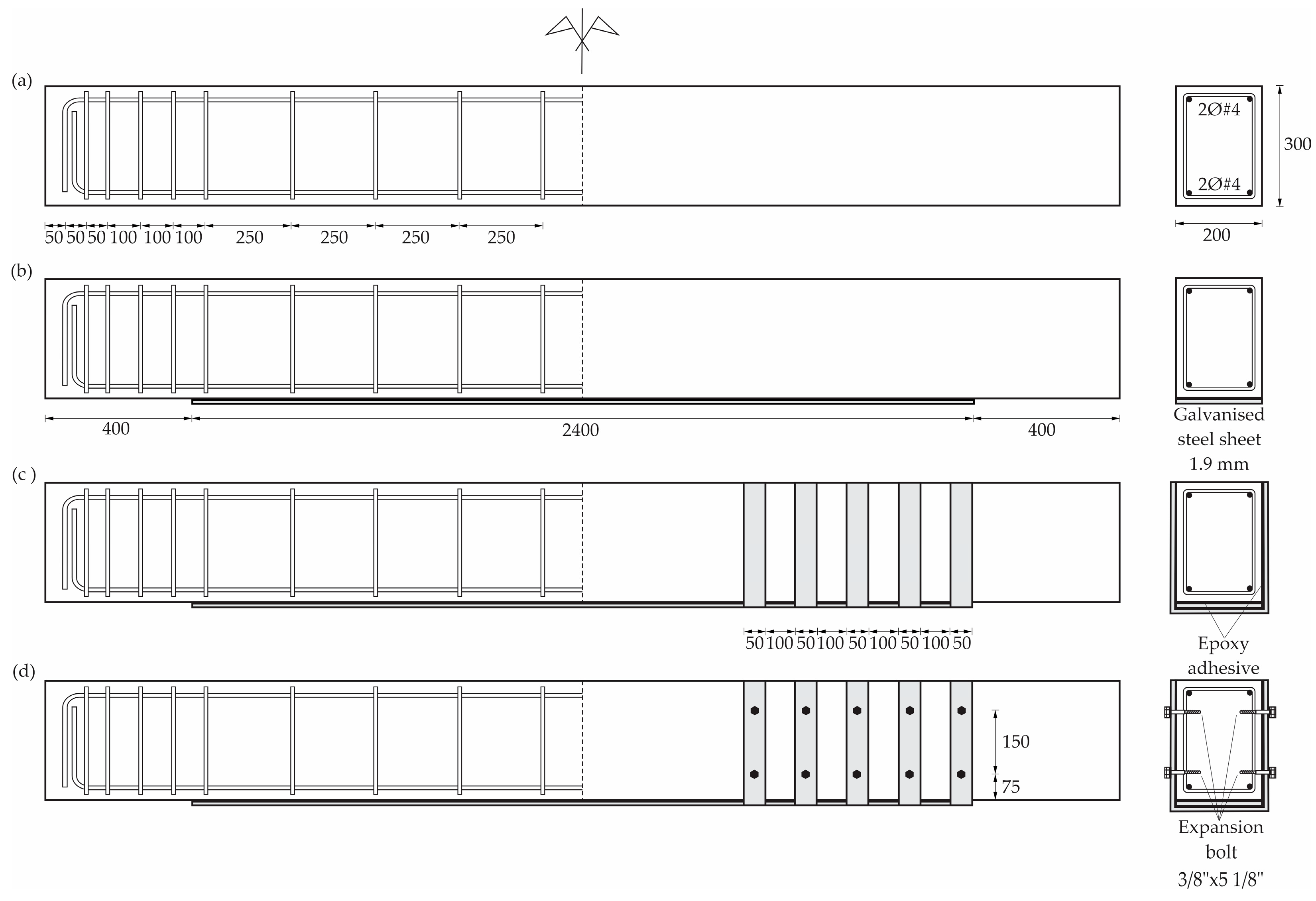
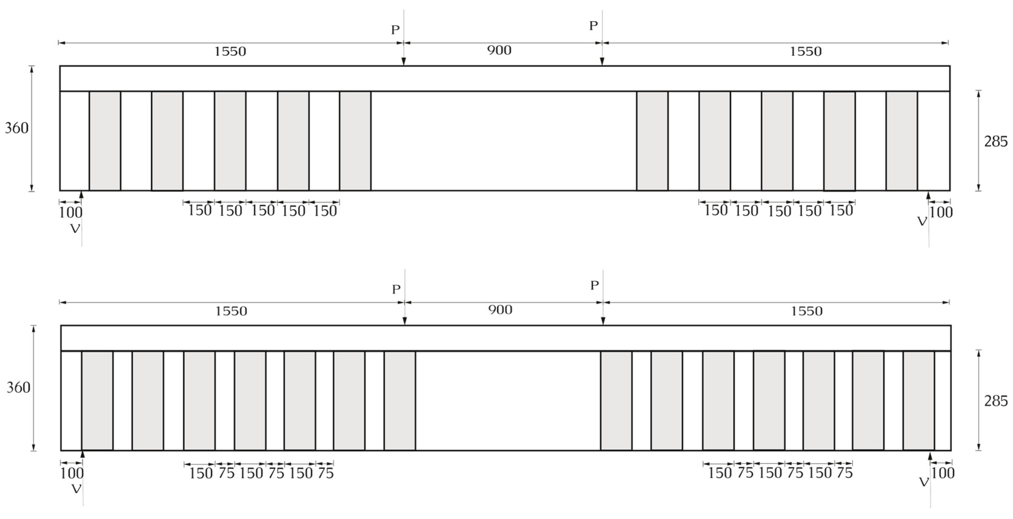
The beam specimens were prepared following a rigorous construction protocol, beginning with the assembly of the longitudinal and transverse reinforcement cages, fabricated from deformed steel bars manufactured in accordance with the requirements of ASTM A615/A615M-22 [36], Grade 60 and arranged according to the dimensions specified in the experimental design. The reinforcement was placed as illustrated in Figure 4, ensuring full compliance with the required internal spacing, structural geometry, and concrete cover. Once the reinforcement cages had been assembled, they were positioned inside the wooden formwork, which had been previously aligned and levelled.
Next, the concrete was prepared using a manual mixing process assisted by a mechanical mixer, to ensure a homogeneous distribution of the components and to minimise variability associated with the production process. The concrete was poured into the formwork in a single, continuous operation to avoid significant differences in settlement or initial compaction. Twenty-four hours after casting, and once it had been verified that the concrete had reached the minimum handling strength without compromising structural integrity, the lateral formwork was removed. Subsequently, curing was carried out under site conditions using potable water at a controlled temperature of approximately 21 °C for a continuous period of 28 days, in accordance with the recommendations of ASTM C31/C31M-23 [38] for the preparation and curing of concrete test specimens.
After completion of the curing phase, the beams underwent surface preparation in the region subjected to tensile stresses, consisting of uniform mechanical sanding. This treatment was intended to increase the surface roughness of the concrete, thereby promoting both chemical adhesion and mechanical interlock between the hardened concrete and the external reinforcement. Subsequently, galvanised steel sheets were installed using a structural epoxy adhesive. The adhesive was applied and the sheets positioned using a metal spatula to ensure a continuous, void-free layer to guarantee intimate contact between the concrete substrate and the metallic reinforcement, an essential condition for satisfactory behaviour during flexural testing.
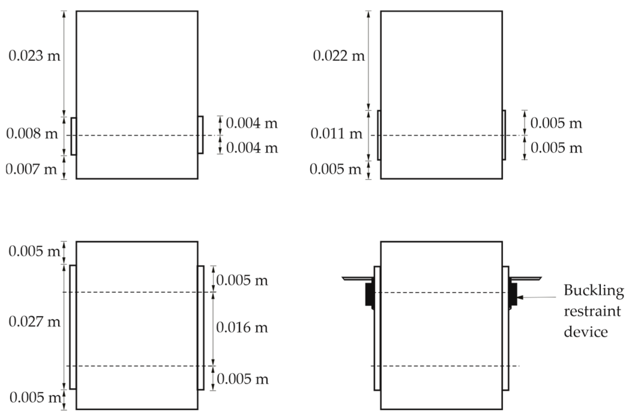
Of the four beams constructed, three were externally reinforced with galvanised steel sheets, while one specimen (designated VP-001) was left without additional reinforcement to serve as the control for comparative evaluation of structural performance. This distribution enabled a differentiated analysis of the influence of external reinforcement on the load-carrying capacity and flexural response of the tested elements. The specific reinforcement configurations considered in this study, illustrated in Figure 5, are described below:
  • VP-002: This beam was strengthened by bonding a galvanised steel sheet 200 mm wide and 2400 mm long to the soffit, corresponding to the region subjected to tensile stresses. Prior to installation, the concrete surface was prepared through mechanical sanding and subsequent cleaning. A controlled layer of structural epoxy adhesive was then applied to ensure effective bonding between the galvanised sheet and the concrete substrate.
  • VP-003: In addition to the bottom sheet used in VP-002, this beam incorporated ten lateral elements configured as U-wraps, each 50 mm wide and arranged symmetrically on both sides of the specimen. The U-wraps were installed, leaving an unreinforced central region of 1100 mm, with a uniform spacing of 100 mm between successive wraps and maintaining a clear distance of 400 mm from each beam end to the first U-wrap.
  • VP-004: This beam replicated the configuration used in VP-003, incorporating a bottom plate and side U-wraps. The latter were secured using a system of 3/8 in. × 5 1/8 in. non-through expansion anchor bolts, with a concrete bond capacity of 24 kN in tension and 58 kN in shear, in addition to an epoxy adhesive. The inclusion of these mechanical anchors was intended to enhance the mechanical interlock of the external reinforcement, improve load transfer between each U-wrap and the concrete substrate, and reduce the likelihood of separation or delamination of the reinforcement under applied loading.
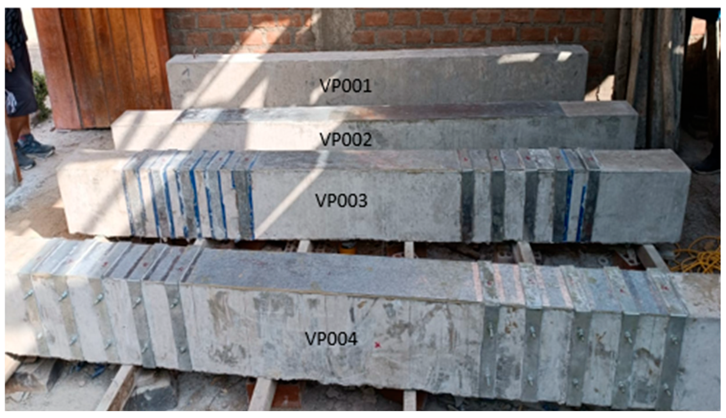
Figure 5. Specimens reinforced with galvanised steel sheet: VP-002, VP-003, and VP-004.
Infrastructures 11 00080 g005

2.3. Experimental Planning, Procedure Execution, and Measuring Devices

To evaluate the structural behaviour of RC beams externally reinforced with galvanised steel sheets, an experimental programme was designed to establish the procedure for determining flexural strength under four-point bending. In this configuration, simply supported beams are loaded by two forces applied symmetrically at one-third and two-thirds of the effective span, producing a central region of constant bending moment. This programme enabled the assessment of the influence of external reinforcement on stiffness, ultimate load capacity, and the failure mechanisms observed during testing, including phenomena specific to external sheet reinforcement such as uplift, delamination, or loss of adhesion at the ends.

2.3.1. Test Planning

Four RC beams were constructed, whose geometric dimensions and mechanical properties were defined in Section 2.1, with the objective of ensuring test reproducibility and comparability among the different external reinforcement schemes. These beams were subsequently tested at the Centro Peruano Japonés de Investigaciones Sísmicas y Mitigación de Desastres (CISMID) in Lima, Peru, a laboratory equipped for full-scale quasi-static testing.
The experimental programme consisted of four-point bending tests, in which two monotonic loads were applied at positions corresponding to one-third and two-thirds of the effective span of the specimen. This configuration generated a central region of constant bending moment, a necessary condition for isolating the flexural response and accurately evaluating the contribution of the galvanised steel sheet reinforcement in the tension zone.
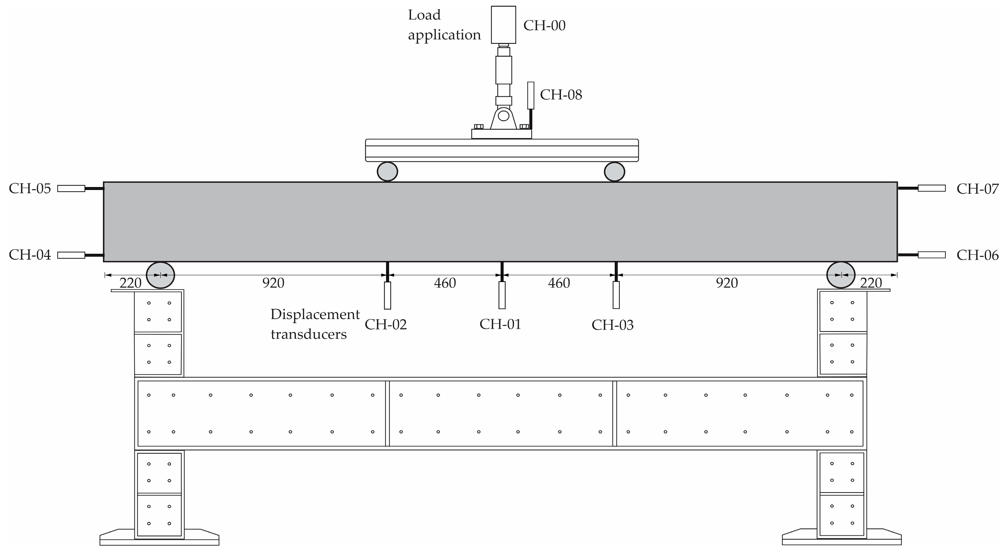
The reaction system comprised a rigid steel frame equipped with a 490 kN capacity hydraulic actuator, firmly anchored to a reaction slab to prevent undesired lateral or vertical displacement. Each beam was supported on two simple supports, with an effective span of 2760 mm, ensuring adequate stress distribution during load application.

2.3.2. Measurement System and Instrumentation

The structural response was recorded using a data acquisition system comprising a 490 kN load cell installed on the hydraulic actuator to measure the applied load accurately; eight (08) linear variable differential transformers (LVDTs) with a range of up to 200 mm and a resolution of 0.02 mm, strategically positioned along the specimen (mid-span, loading points, and supports); signal amplifiers to condition the sensor outputs; and a Kyowa analogue-to-digital converter, which transformed the analogue signals into digital data for processing in the Visual LOG TDS-7130 software. The eight LVDTs installed on each beam were arranged as follows in Figure 6.
Prior to each test, individual calibration of both the load cell and the LVDTs was conducted to verify linearity, sensitivity, stability, and proper integration with the TDS-7130 data acquisition system, thereby ensuring the reliability of the measurements obtained.
The applied load was generated by a unidirectional hydraulic jack powered by a constant-pressure pump. Together, the actuator, load cell, and acquisition system constituted the mechanism responsible for continuously applying, recording, and monitoring the load throughout the testing procedure.
Finally, the steel reaction frame provided the rigidity and stability required to ensure correct force transmission, preventing unwanted displacements and guaranteeing proper alignment between the actuator and the designated load application points.

2.3.3. Implementation of the Procedure

The load was applied under displacement control using the hydraulic actuator, following regular increments that allowed the progressive evolution of the structural response to be recorded. Throughout the test, the principal mechanically relevant variables were monitored: applied load (kN), vertical displacements, maximum deflection, and the type of final failure.
The test continued until the collapse of the beam was identified by one or more of the following mechanisms: extensive cracking, the formation of plastic hinges, partial or total detachment of the external reinforcement, and spalling of the concrete cover. The identification of these stages enabled the structural response to be characterised in four phases: initial elastic behaviour, crack initiation and propagation, yielding of the internal reinforcement, and, finally, collapse.
For the beams externally reinforced with galvanised steel sheets, additional mechanisms associated with the performance of the bonded reinforcement were observed, including progressive sheet detachment, end slip, localised deformations in the anchorage regions, and, in some cases, interaction between the U-wraps and the bottom sheet. These mechanisms were critical for the subsequent interpretation of the global behaviour of the strengthened system.
It should be noted that all instrumentation and data acquisition procedures were conducted using the maximum displacement verification method at the centre of the beam’s effective span, in accordance with the guidelines set out in ASTM E2309/E2309M-20 [39]. This ensured the reliability, traceability, and reproducibility of the experimental results—conditions that are essential for the development of future analytical or numerical models.

2.3.4. Data Processing and Analysis

After the tests, the load–displacement curves recorded in real time by the acquisition system were analysed in order to accurately characterise the structural behaviour of the beams under bending: these curves made it possible to identify the elastic and inelastic regions, as well as the yield, maximum, and ultimate loads and corresponding displacements, thereby enabling the evaluation of the load-carrying capacity and ductility.
Likewise, the load–displacement results of the beams with and without reinforcement were compared to evaluate the effectiveness of the galvanised sheets and, in the corresponding cases, the U-wraps and mechanical anchors. These comparisons made it possible to quantify increases in ultimate capacity, initial stiffness, and dissipated energy.

2.4. Analytical Assessment of the Behaviour of the RC Beam

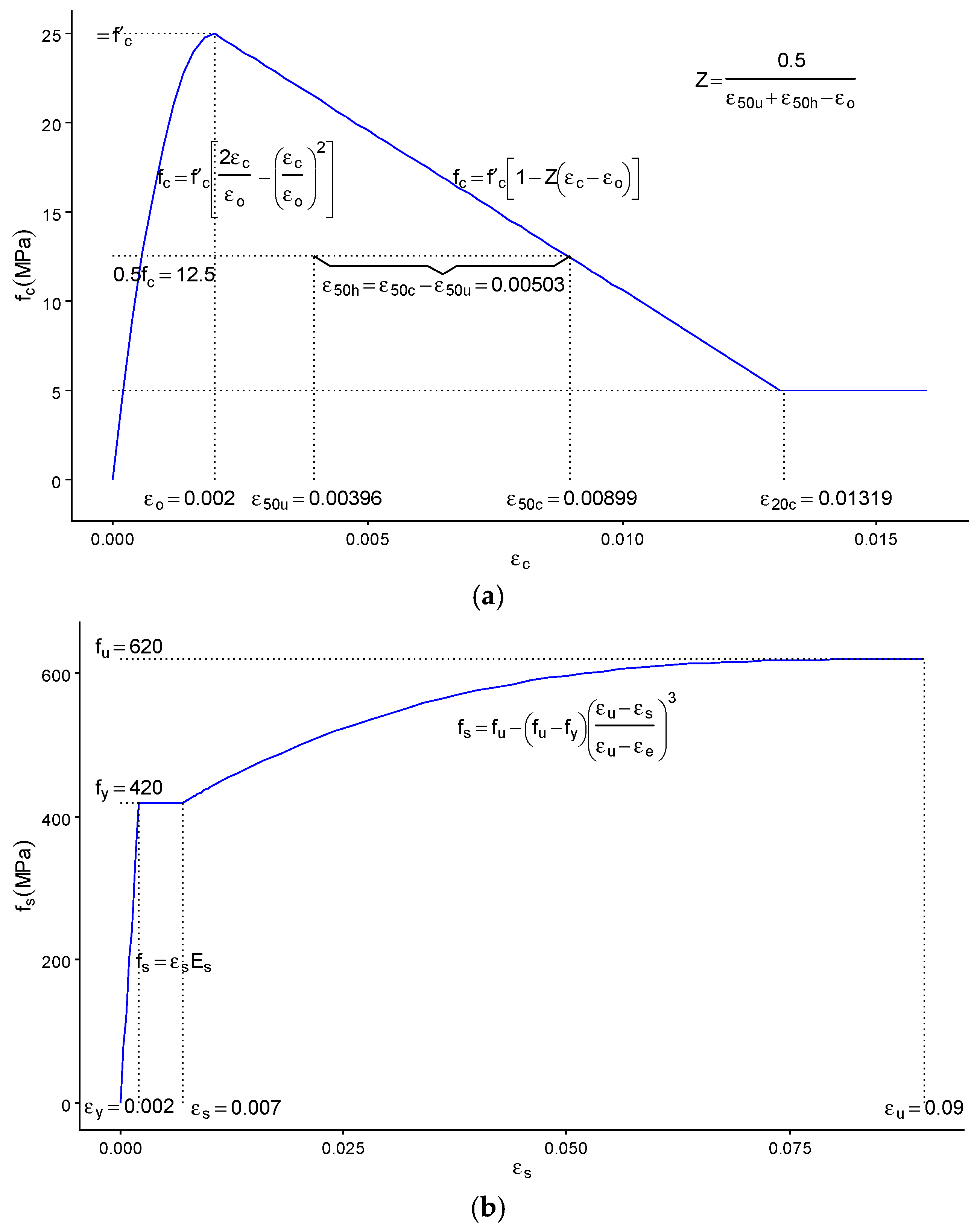
The non-linear model of concrete confined by rectangular stirrups proposed by Kent and Park [40] was employed. This model identifies three regions: AB, represented by a concave downward parabolic curve, reaches its maximum stress when the concrete strain is 0.002; BC is a descending linear branch with a negative slope; and CD is a horizontal plateau, as illustrated in Figure 7a.
Similarly, the behaviour of the longitudinal reinforcing steel was modelled using the generalised constitutive law developed by Andriono and Park [41], which also comprises three regions: an initial linear–elastic stage up to a strain of 0.002; a yielding or strain-hardening transition region between 0.002 and 0.007; and a strain-hardening region extending from 0.007 to 0.09, as shown in Figure 7b.
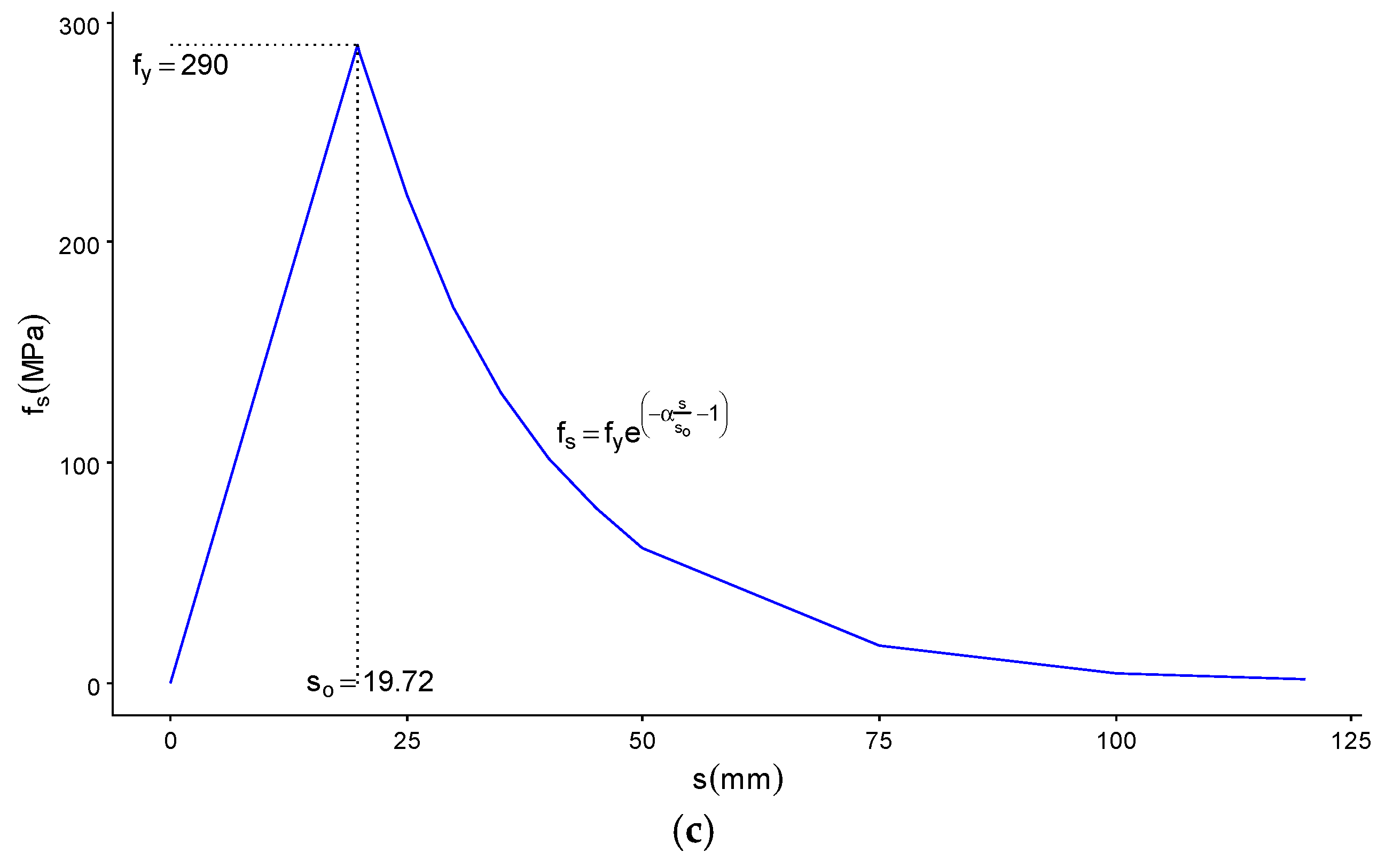
Regarding the behaviour of the galvanised steel sheet attached to the underside of the beams, the model proposed by Lu et al. [42] was adapted. As noted by these authors, previous studies have demonstrated that the bond strength between the steel sheets and the concrete is directly proportional to the square root of the fracture energy. Based on this premise, they proposed a simplified model that relates the shear stress in the epoxy adhesive to the corresponding slip through an exponential function.
Using the simplified model of Lu et al. [42] as a reference, a relationship between the stress in the steel sheet and the vertical displacement of the beam was established, comprising two distinct behavioural regions. The first region exhibits linear behaviour up to a displacement of 19.72 mm, corresponding to the maximum displacement within the elastic range, as determined from flexural tests. The second region follows an exponentially decreasing trend, in which the stresses in the steel sheet become small at greater displacements in the RC beam due to the loss of adhesion between the steel sheet and the beam, as illustrated in Figure 7c.
It should be noted that these analytical models were adopted because they require only the compressive or tensile strengths and the corresponding deformation values. In this study, experimental tests were conducted to determine the strengths of the concrete and the galvanised steel, whereas the deformation parameters for the concrete and reinforcing steel were taken from the models proposed by Kent and Park [40] and Andriono and Park [41], respectively, which were not validated within the scope of this research.
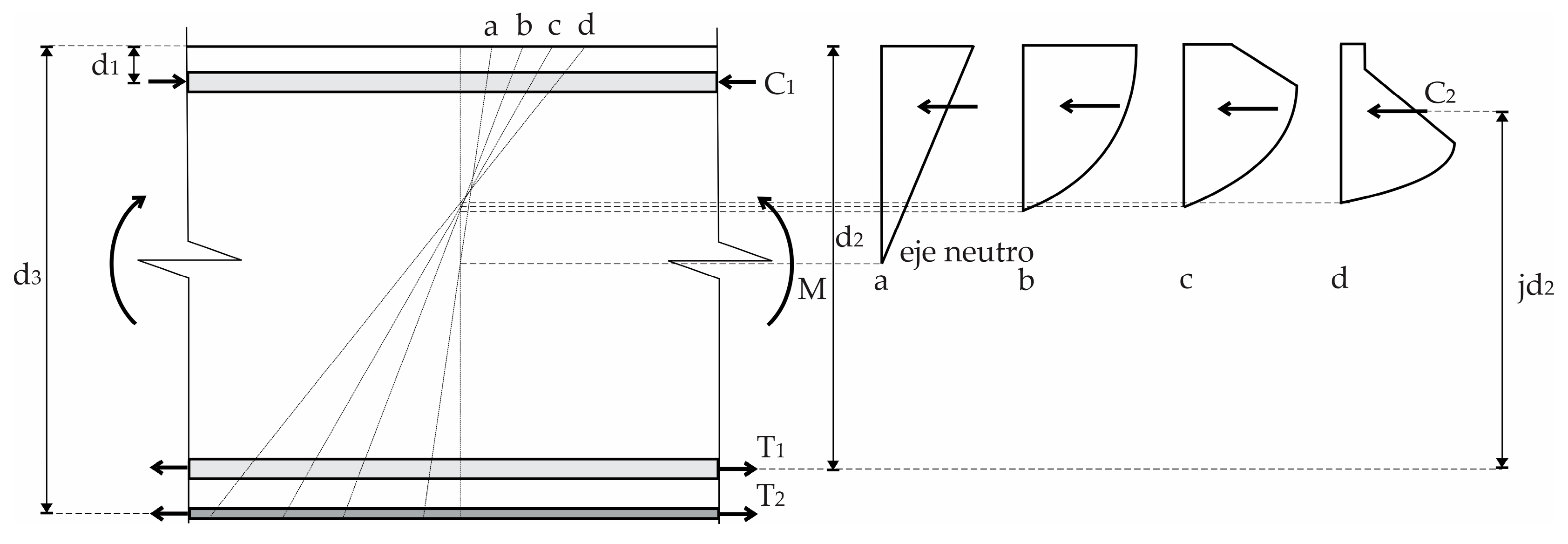
The sectional behaviour was determined by controlling the strains in the confined concrete from 0.0002 to 0.015, with increments of 0.0002, which were assumed to vary linearly with the distance from the neutral axis. The position of the neutral axis was estimated using the Solver tool in Microsoft Excel, assuming equilibrium of internal forces within the section. Figure 8 illustrates the resulting stress–strain profile, showing the shape of the compressive stress block at different loading stages, as well as the tensile stresses in the lower reinforcing steel and the galvanised steel sheet, and the compressive stress in the upper reinforcing steel.
Then, to construct the moment–curvature diagrams, the curvature along the beam was determined from the variations in the position of the neutral axis and the strains developed between cracks, using Equation (1). Similarly, the bending moment was obtained using Equation (2), applying strain compatibility under the assumption that plane sections remain plane after bending, and enforcing force equilibrium by employing the previously described stress–strain relationships.
Φ = ε c k d
M = α f c b k d h 2 γ k d + i = 1 n f s i A s i h 2 d i
where
ε c is the strain of the extreme compression fibre;
α ,   γ are the average stress and centroid factors for any strain;
f c is concrete with a compressive strength of 25 MPa;
b is the beam width of 200 mm;
k d is the depth of the neutral axis;
h is the beam depth of 300 mm;
d i is the distance from the extreme compression fibre to the centroid of the steel;
f s i is the stress of the steel in each layer;
A s i is the steel area in each layer.
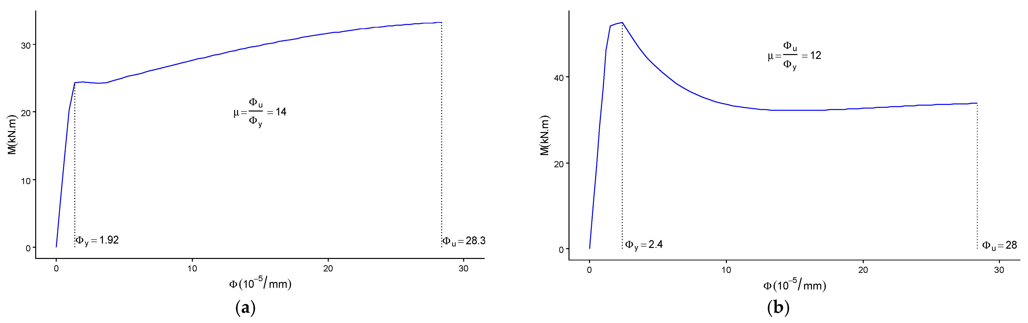
Figure 9a,b present the moment–curvature diagrams for the RC beam section without and with the galvanised steel sheet, respectively, together with the corresponding ductility values for each case.
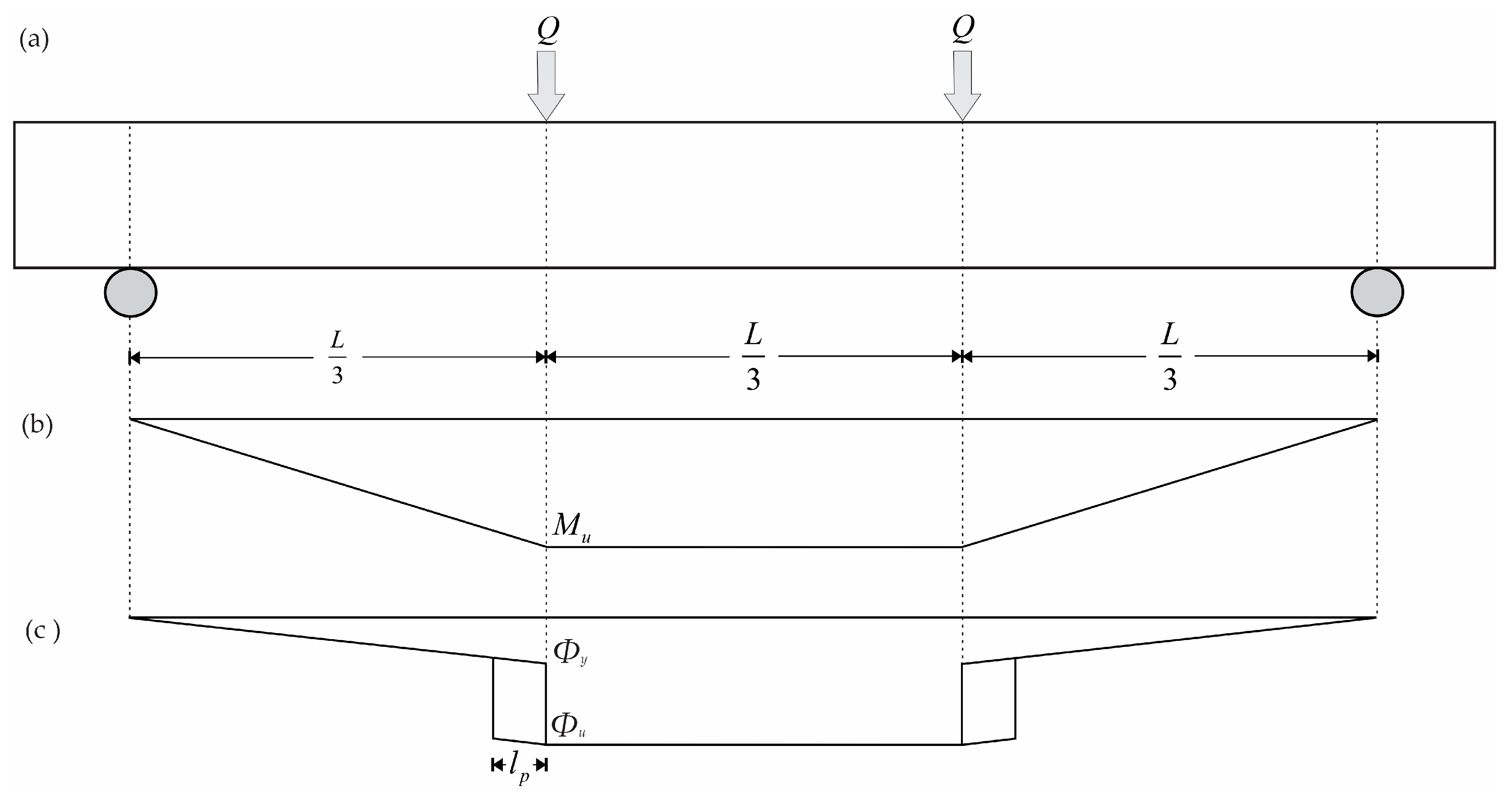
Next, using the ultimate curvature and yield curvature obtained from the moment–curvature diagrams [40,43], the idealised deflections were determined by integrating the product of the curvature and the distance to the point of rotation, as illustrated in Figure 10c.
Equation (3) represents the area (Figure 10c) corresponding to the product of the curvature and the distance to the point of rotation. Similarly, the load was obtained using Equation (4).
= 2 13 216 Φ y L 2 + Φ u Φ y L 2 72 + l p l p 2 + L 6
Q = 2 3 M l
where
Δ is the deflection at mid-span of the beam;
L is the effective span of the beam (2760 mm);
l p is the plastic hinge length (185 mm);
Φ u is the ultimate curvature;
Φ y is the elastic curvature;
Q is the total load applied at one-third and two-thirds of the effective span;
M is the moment determined by the product of the internal forces and the distance to the centroid.
The plastic hinge length was determined using Corley’s [44] empirical equation, expressed in Equation (5):
l p = 0.5 d + 0.2 d z d
where
d is the effective depth (250 mm);
z is half of the effective span of the simply supported beam (1380 mm).

3. Results

To evaluate the behaviour of RC beams externally reinforced with galvanised steel sheets, a series of laboratory tests was carried out in accordance with the relevant ASTM standards to ensure the consistency, repeatability, and reliability of the results. These test results are described below:

3.1. Behaviour and Failure Mode

Table 3 presents the experimental results obtained for the four RC beams: one beam without sheets and three beams strengthened with externally bonded galvanised steel sheets. It also includes the results obtained from analytical models for beams with and without external reinforcement. The yield load (Pe), ultimate load (Pu), and failure load (Pf) were determined from the load–displacement curves, with the former corresponding to the elastic limit and the latter to the maximum load attained by the beam. These results indicate a progressive increase in strength as the reinforcement configuration is introduced and optimised. In addition, the ductility, as determined from the load–displacement curves, indicates a slight improvement in the deformation capacity of beams VP-003 and VP-004 strengthened with external reinforcement; however, VP-003 experienced a decrease in deformation capacity associated with the formation of diagonal cracks and degradation of the coating layer.
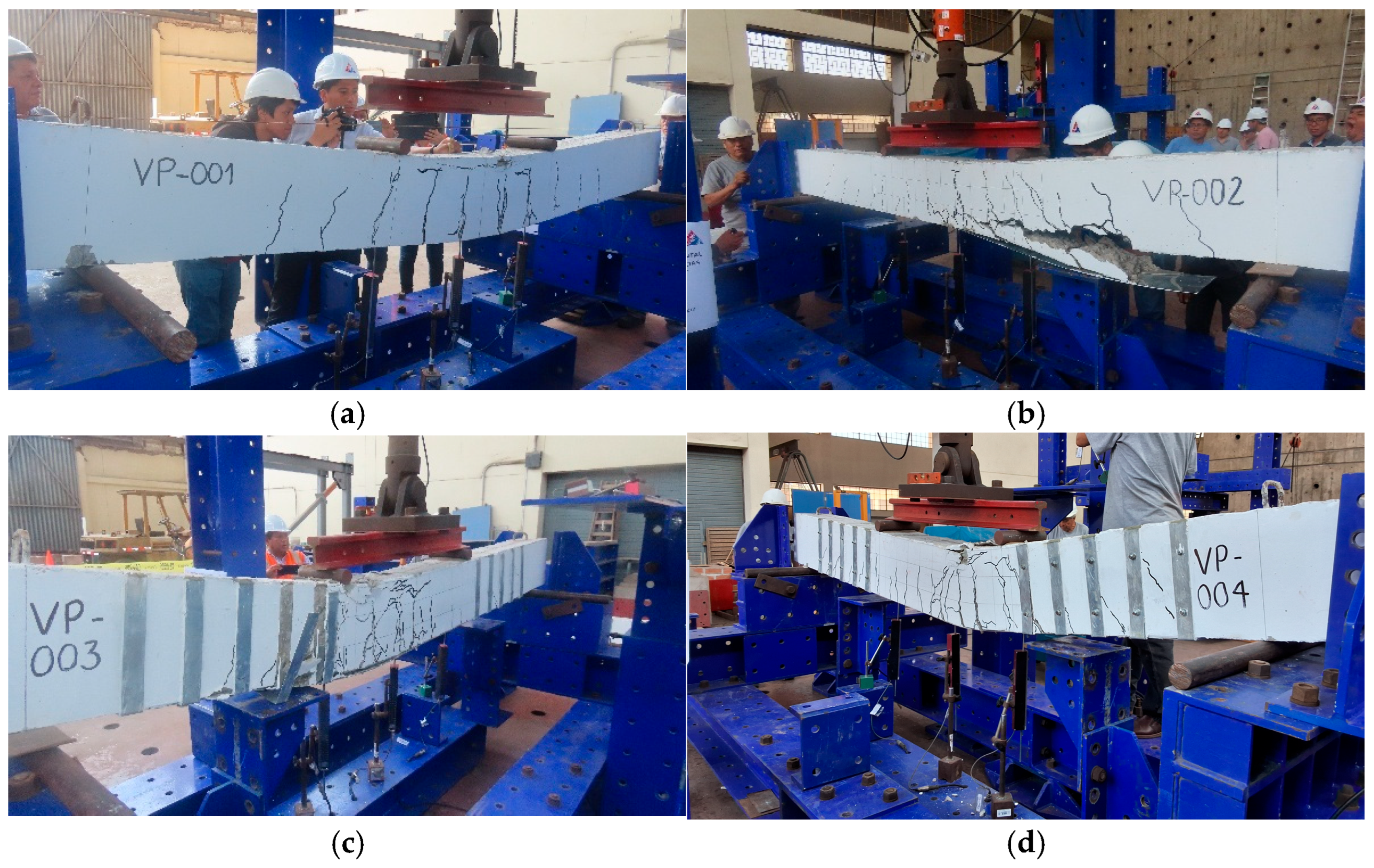
Figure 11 illustrates the cracking patterns and failure modes of the tested specimens. For beams VP-001, VP-003, and VP-004, the first cracks developed in the region of maximum bending moment, whereas for beam VP-002, the initial cracks appeared near the supports. In all cases, cracking occurred when approximately 40% to 50% of the maximum load had been applied.
Beam VP-001, without a sheet, exhibited ductile behaviour, characterised by distributed cracking and significant deformation prior to failure, and therefore, it served as a reference for assessing the influence of strengthening with galvanised steel sheets. The ultimate load of the control beam (VP-001) was 73.22 kN, and failure occurred in flexure with a maximum deflection of 112 mm, as shown in Figure 11a.
Beam VP-002, strengthened with a steel sheet bonded to the bottom face, showed an increase in initial stiffness and a reduction in deformation within the elastic range. However, it exhibited brittle failure due to debonding of the sheet and loss of adhesion between the galvanised steel and the concrete. Shear cracks initiated near the beam ends at a load of 74 kN and subsequently propagated horizontally, with several cracks forming above the steel sheet at the interface with the main horizontal crack. The ultimate load was 97.50 kN, corresponding to a deflection of 8.44 mm, as shown in Figure 11b.
Conversely, beam VP-003, also strengthened using bonded reinforcement, exhibited ductile failure associated with debonding, as the epoxy adhesive alone was insufficient to prevent steel sheet detachment, even with the incorporation of U-wraps in the inelastic response zone. The behaviour of this beam was like that of beam VP-004; however, the first cracks appeared at a load of 57 kN. The mid-span deflection reached 11.76 mm at an ultimate load of 111.04 kN, as shown in Figure 11c.
Beam VP-004, strengthened with galvanised steel sheets and mechanical anchor bolts, exhibited ductile failure. Although its load-bearing capacity was like that of the beams strengthened without bolts, this specimen demonstrated more stable behaviour, improved energy dissipation, and a more controlled cracking pattern (Figure 11d). In this case, flexural cracking initiated at 62 kN, and flexural failure occurred when the load reached 69.36 kN. Owing to load concentration, cracks developed around the bolt locations and propagated with increasing load until failure. The specimen ultimately lost strength at 122.87 kN and the mid-span deflection of 14.58 mm; however, complete failure did not occur, as the steel sheet and anchor bolts remained engaged with the beam and continued to carry tensile forces until flexural delamination took place.
The sheets used in beams VP-002 and VP-003 did not contribute significantly to an increase in strength, as they were located entirely within the flexural zone. Although these sheets prevented the formation of cracks within the reinforced region, cracking propagated until a weak zone was encountered at the end of the sheet, leading to crack localisation and premature failure of the beams, as illustrated in Figure 11b,c.
All beams reinforced with galvanised steel sheets showed similar initial stiffness, with comparable elastic response until the onset of creep. However, after reaching maximum load capacity, they lost load capacity due to detachment of the steel sheet, loss of adhesion, diagonal cracks, or detachment of the coating.

3.2. Load–Displacement Behaviour

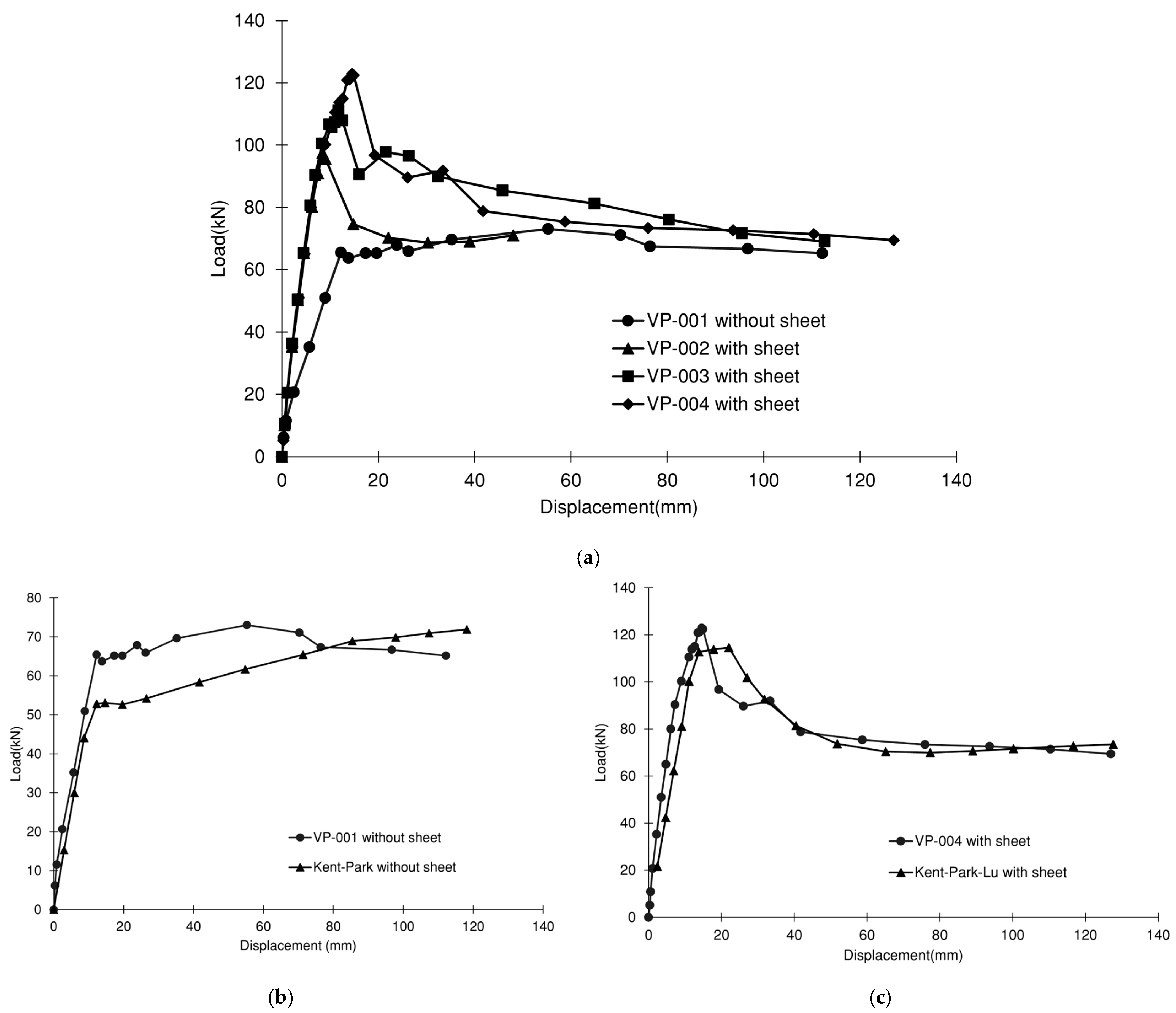
The load–deflection curves at mid-span for all externally reinforced beams (VP-002, VP-003, and VP-004) and the control beam VP-001 are presented in Figure 12a. In the linear range, the elastic loads of the reinforced beams were 39.0%, 63.0%, and 69.0% higher than that of the unreinforced beam, respectively. At ultimate conditions, the load capacity increased by 33.0%, 52.0%, and 68.0%, respectively. The deflections in the linear range were reduced by 39.0%, 20.0%, and 10.0% relative to beam VP-001. Similarly, the failure deflection in the inelastic range decreased by 57% for beam VP-002, whereas for beams VP-003 and VP-004, it increased by 1.0% and 13.0%, respectively, compared with the unreinforced beam. Beam VP-001 displays linear behaviour with a lower slope than that of the externally reinforced beams, followed by a non-linear response up to the maximum load and a subsequent decline until failure, exhibiting ductile behaviour. In contrast, beam VP-002 shows a steeper slope in the elastic region, indicating increased stiffness; however, in the inelastic region, it undergoes an abrupt loss of load-carrying capacity due to debonding of the galvanised sheet and detachment of the concrete cover, corresponding to a brittle failure. Beam VP-003 demonstrates intermediate behaviour, with a similar response to VP-004, though still limited by debonding. Finally, beam VP-004 stands out for its wider curve, greater deformation capacity, and gradual reduction in slope, indicating controlled ductile failure attributable to the combined action of the epoxy adhesive and anchor bolts. This type of behaviour has been reported in experimental studies [8,9], which indicate that the inclusion of anchors in metallic reinforcements enhances stress transfer and prevents premature delamination.
On the other hand, Figure 12b,c compare the analytically predicted load–displacement responses with the experimental results for beams VP-001 and VP-004. The analytical model adequately reproduces both the linear and non-linear response behaviour, showing good agreement with the experimental measurements. Overall, the developed analytical models exhibit deviations of approximately ±13% in load and displacement relative to the experimental results. This level of accuracy is considered acceptable according to the typical engineering standard. In such a case, the use of the model in future studies may be used or improved.
In addition, the analytical models for beams VP-001 and VP-004 exhibited a slight discrepancy in initial stiffness compared with the experimental results, as the model does not account for the contribution of the U-wraps on the side faces of beam VP-004, which are bonded with epoxy adhesive and secured using an expansion bolt.
Overall, the experimental results confirm that the use of galvanised steel sheets as external reinforcement increases the flexural strength and enhances the initial stiffness of RC beams. The effectiveness of this reinforcement, however, is strongly dependent on the quality of adhesion and the type of anchorage employed. Beams reinforced solely with epoxy-bonded sheets exhibited moderate increases in load capacity but experienced premature failure due to delamination. In contrast, the beam incorporating mechanical anchor bolts demonstrated a more stable response and ductile failure, highlighting the critical role of combining chemical adhesion with physical fastening to optimise the performance of external sheet reinforcement systems.

4. Discussion

The ductile failure behaviour of beam VP-001, which lacked an external reinforcement sheet, is consistent with the observations of Sevuk and Arslan [10], who reported similar failure in three beams due to crushing of concrete in the compression zone.
Beam VP-002, reinforced with a galvanised sheet bonded to the bottom flange, exhibited brittle failure. This behaviour aligns with previous studies [1,2,7,8,11,43], which indicate that diagonal shear cracks at the ends of the reinforcement sheet led to detachment of both the sheet and the concrete cover, resulting in simultaneous shear failure of the beam and separation of the reinforcement.
On the other hand, the failure of beam VP-003 is consistent with experimental results reported by other authors of [4,7,17,43], who demonstrated that bonded steel sheets tend to detach at the ends despite the use of U-wraps. The premature detachment observed in beams VP-002 and VP-003 is attributed to inadequate adhesion between the steel sheet and the concrete, aggravated by insufficient surface roughness of the steel sheet, which limited the chemical bonding of the epoxy. In addition, the low contact pressure between the sheet and the concrete during curing resulted in insufficient shear strength, thereby reducing the effectiveness of the adhesive.
In contrast, the behaviour of beam VP-004 corroborates recent studies [4,5,18], confirming that combining epoxy adhesive with mechanical anchorage provides a more reliable bond and superior resistance to premature debonding.
In terms of ductility, VP-001 exhibited lower ductility than VP-003 and VP-004, but greater ductility than VP-002. Ductility is defined here as the ratio of failure to elastic displacement ( d f / d e ), where the elastic displacement corresponds to the point where the load–displacement curve ceases to be linear, and the failure displacement represents the maximum displacement prior to failure. These observations are consistent with research [7,14,15,17,34], which shows that ductility may increase or decrease depending on the configuration of the reinforcement sheets and the adhesion mechanisms employed.
When comparing the experimental results with analytical models based on Kent–Park and Kent–Park–Lu, the theoretical predictions closely approximate the observed experimental behaviour. For both reinforced and unreinforced beams, the models yielded values in close agreement with the experimental data, with minimal differences, confirming their validity in representing the non-linear response of RC beams, both with and without external metal reinforcement [6,7].
The design and construction of the beams adhered to applicable technical and regulatory specifications, ensuring the reliability of the experimental tests. Furthermore, the comparative analysis of experimental and theoretical results enabled a clear assessment of the influence of metal reinforcement on strength, stiffness, and ductility, confirming its effectiveness. The strong correlation between the Kent–Park and Kent–Park–Lu models and the experimental results demonstrates that these models adequately reproduce the non-linear behaviour of the beams, validating their applicability to RC elements.
It should be noted that the load-carrying capacity of the beam decreases once a curvature of 24 × 10−6 mm−1 is reached (Figure 9b). This value is slightly higher than that reported by Oehlers and Moran [1], who identified a curvature of 15 × 10−6 mm−1. This curvature corresponds to the point at which the beam attains its maximum elastic behaviour. To reach this state, detachment of the galvanised steel sheet must be prevented using both chemical and mechanical anchorage techniques, such as those implemented in specimen VP-004. Beyond the elastic limit, the beam capacity progressively decreases until its response becomes like that of beam VP-001. This behaviour is attributed to the loss of shear strength of the epoxy adhesive, which, upon reaching stresses of approximately 5 MPa, leads to the detachment of the steel sheets [16].
In summary, the results presented in Table 3 and Figure 12 indicate that reinforcement with galvanised steel sheets enhances both the flexural strength and the initial stiffness of RC beams, in agreement with the findings reported in [4,6,7,8,9,10,11,12,13,14]. The configuration incorporating mechanical anchors performed best, preventing delamination and maintaining a ductile failure mode. Although the gain in ultimate strength was moderate, the overall structural behaviour was more stable and reliable. These findings are consistent with previous studies [2,4,5,8,19,21,22], which highlight the effectiveness of anchor-assisted metal reinforcement as a practical and reproducible method for improving the structural performance of RC beams.

5. Conclusions

This study reports the results of experimental investigations into the flexural performance of reinforced concrete (RC) beams strengthened with galvanised steel sheets. The experimental programme comprised four rectangular RC beams with dimensions of 200 mm × 300 mm × 3200 mm, which were subjected to monotonically increasing four-point loading. Three different strengthening configurations were considered. In addition, an analytical model was formulated to simulate the non-linear behaviour of the RC beams. Based on the experimental and analytical analyses, the main conclusions of this study are presented below:
  • RC beams VP-002, VP-003, and VP-004 externally strengthened with galvanised steel sheets exhibited significant increases in both elastic and ultimate load capacities compared with the control beam VP-001. The elastic load capacity increased by 39%, 63%, and 69%, respectively, while the ultimate load capacity increased by 33%, 52%, and 68%, depending on the configuration of the steel sheets. Notably, beam VP-004 demonstrated the best overall performance, as it was reinforced with galvanised steel sheets bonded to the underside using epoxy adhesive and complemented by vertical U-wraps incorporating expansion bolts, which provided additional mechanical anchorage. These results demonstrate the effectiveness of the galvanised steel sheet reinforcement system in enhancing flexural performance.
  • The ductility of beams VP-003 and VP-004 increased by 22% compared with the control beam VP-001. In contrast, the ductility of beam VP-002 decreased by 33%, owing to premature failure associated with the loss of concrete cover and debonding of the external reinforcement sheet. Consequently, beams VP-001, VP-003, and VP-004 exhibited ductile behaviour, as failure occurred gradually; in particular, the external reinforcement of beam VP-004 remained effectively integrated into the section until the ultimate load was reached. Conversely, beam VP-002 showed reduced ductile performance accompanied by delamination, as the galvanised steel sheets detached prematurely, whereas VP-003, despite failing due to delamination, retained its deformation capacity.
  • The analytical models Kent–Park for beams without sheets and Kent–Park–Lu for beams with sheets proved suitable for estimating load capacity, with discrepancies of approximately 13% and 9%, respectively, relative to the experimental results for specimens VP-001 and VP-004. Furthermore, these models adequately predicted ductility, yielding differences of approximately 10%, when compared with the experimental measurement. This level of accuracy is considered acceptable within typical engineering standards; however, these models may be further refined and applied in future studies.

Author Contributions

Conceptualisation, G.C.; methodology, G.C., D.R., E.R., B.B., D.A. and D.Q.; validation, G.C. and D.Q.; formal analysis, G.C. and D.A.; investigation, G.C., D.R., E.R. and D.A.; data curation, G.C. and D.Q.; writing—original draft preparation, G.C., D.R., E.R., B.B. and D.A.; writing—review and editing, G.C., B.B., D.A. and D.Q.; visualisation, G.C.; supervision, D.Q.; project administration, G.C.; funding acquisition, G.C. All authors have read and agreed to the published version of the manuscript.

Funding

This research and the APC were funded by Universidad Tecnológica del Perú (P-2024-LIM-34), approved by Rector’s Resolution No. 0131-2024/R-UTP, 2 July 2024.

Data Availability Statement

The original contributions presented in this study are included in the article. Further inquiries can be directed to the corresponding author.

Acknowledgments

We thank the Centro Peruano Japonés de Investigaciones Sísmicas y Mitigación de Desastres (CISMID) of the Universidad Nacional de Ingeniería for providing the laboratory facilities.

Conflicts of Interest

The authors declare no conflicts of interest.

References

  1. Oehler, D.J.; Moran, J.P. Premature failure of externally plated reinforced concrete beams. J. Struct. Eng. 1990, 116, 978–995. [Google Scholar] [CrossRef] [Scilit]
  2. Arslan, G.; Sevuk, F.; Ekiz, I. Steel plate contribution to load-carrying capacity of retrofitted RC beams. Constr. Build. Mater. 2008, 22, 143–153. [Google Scholar] [CrossRef] [Scilit]
  3. Vilnay, O. The analysis of reinforced concrete beams strengthened by epoxy bonded steel plates. Int. J. Cem. Compos. Lw. Conc. 1988, 10, 73–78. [Google Scholar] [CrossRef] [Scilit]
  4. Wakjira, T.G.; Ebead, U. Strengthening of reinforced concrete beams in shear using different steel reinforced grout techniques. Struct. Conc. 2021, 22, 1113–1127. [Google Scholar] [CrossRef] [Scilit]
  5. Hassanen, M.A.; Raoof, M. RC beams upgraded with externally bonded plates. In Advanced Technology in Structural Engineering; American Society of Civil Engineers: Reston, VA, USA, 2000; pp. 1–8. [Google Scholar] [CrossRef] [Scilit]
  6. Ozbek, E.; Bocek, M.; Aykac, S. Strengthening of RC beams with solid steel plates. Athens J. Technol. Eng. 2016, 4, 291–298. [Google Scholar] [CrossRef] [Scilit]
  7. Tang, H.; Peng, J.; Zhang, J. Influence of further corrosion on structural behavior of corroded reinforced-concrete beam strengthened with steel plate using different strengthening schemes. J. Perform. Constr. Facil. 2020, 34, 04019117. [Google Scholar] [CrossRef] [Scilit]
  8. Oehler, D.J. Reinforced concrete beams with plates glued to their soffits. J. Struct. Eng. 1992, 118, 2023–2038. [Google Scholar] [CrossRef] [Scilit]
  9. Franco, N.; Chastre, C.; Biscaia, H. Strengthening RC beams using stainless steel continuous reinforcement embedded at ends. J. Struct. Eng. 2020, 146, 04020065. [Google Scholar] [CrossRef] [Scilit]
  10. Sevuk, F.; Arslan, G. Retrofit of damaged reinforced concrete beams by using steel plate. In Proceedings of the 2005 Structures Congress: Metropolis and Beyond, New York, NY, USA, 20–24 April 2005; pp. 1013–1020. [Google Scholar] [CrossRef] [Scilit]
  11. Oehler, D.J.; Mohamed, M.S.; Luo, W. Upgrading continuous reinforced concrete beams by gluing steel plates to their tension faces. J. Struct. Eng. 1998, 124, 224–232. [Google Scholar] [CrossRef] [Scilit]
  12. Yelgin, A.N.; Kasap, H.; Ozyurt, M.Z. Strengthening of reinforced concrete slabs by thin steel plates glued with epoxy. Sakarya Univ. J. Sci. 1999, 3, 25–34. [Google Scholar]
  13. Graf, A.A.A.; Bneni, M.; El-Kholy, A.E.; Elkilani, A.M.E.; Ahmad, S.S.E. Experimental and numerical evaluation of compression confinement techniques for HSC beams reinforced with different ratios of high strength steel reinforcement. Frac. Integ. Struct. 2022, 60, 310–330. [Google Scholar] [CrossRef] [Scilit]
  14. Su, R.K.L.; Zhu, Y. Experimental and numerical studies of external steel plate strengthened reinforced concrete coupling beams. Eng. Struct. 2005, 27, 1537–1550. [Google Scholar] [CrossRef] [Scilit]
  15. Foley, C.M.; Buckhouse, E.R. Method to increase capacity and stiffness of reinforced concrete beams. Pract. Period. Struct. Des. Constr. 1999, 4, 36–42. [Google Scholar] [CrossRef] [Scilit]
  16. Mukhopadhyaya, P.; Swamy, N. Interface shear stress: A new design criterion for plate debonding. J. Comp. Constr. 2001, 5, 35–43. [Google Scholar] [CrossRef] [Scilit]
  17. Altin, S.; Anil, Ö.; Kara, E. Improving shear capacity of existing RC beams using external bonding of steel plates. Eng. Struct. 2005, 27, 781–791. [Google Scholar] [CrossRef] [Scilit]
  18. Abdullah, M.D.; Abodi, J.T.; Ojaimi, M.F. Experimental behaviour of the reinforced concrete beams strengthened and repaired with steel plates. J. Eng. Sci. Techno. 2022, 17, 3726–3741. [Google Scholar]
  19. Hamoda, A.A.; Eltaly, B.A.; Sera, R.E.; Liang, Q.Q. Behavior of reinforced concrete stair slabs strengthened with steel plates and near surface mounted steel bars. Eng. Struct. 2023, 292, 116514. [Google Scholar] [CrossRef] [Scilit]
  20. Wang, J.; Liu, J.; Zang, G.; Han, J. Experimental study on shear behavior of hollow slab beam strengthened with pasting steel plates. Intl. J. Struct. Int. 2021, 12, 419–427. [Google Scholar] [CrossRef] [Scilit]
  21. Subedi, N.K.; Baglin, P.S. External plate reinforcement for concrete beams. Struct. Eng. 1998, 124, 1490–1495. [Google Scholar] [CrossRef] [Scilit]
  22. Li, L.Z.; Lo, S.H.; Su, R.K.L. Experimental study of moderately reinforced concrete beams strengthened with bolted-side steel plates. Adv. Struct. Eng. 2013, 16, 499–516. [Google Scholar] [CrossRef] [Scilit]
  23. Barnes, R.A.; Mays, G.C. Strengthening of reinforced concrete beams in shear by the use of externally bonded steel plates: Part 1—Experimental programme. Constr. Build. Mater. 2006, 20, 396–402. [Google Scholar] [CrossRef] [Scilit]
  24. Barnes, R.A.; Mays, G.C. Strengthening of reinforced concrete beams in shear by the use of externally bonded steel plates: Part 2—Design guidelines. Constr. Build. Mater. 2006, 20, 403–411. [Google Scholar] [CrossRef] [Scilit]
  25. Jumaat, M.Z.; Alam, A. Behavior of U and L shaped end anchored steel plate strengthened reinforced concrete beams. Eur. J. Sci. Res. 2008, 22, 184–196. [Google Scholar]
  26. Chai, K.F.; Woon, K.S.; Wong, J.K.; Lim, J.H.; Lee, F.W.; Lee, Y.L. Experimental and numerical study of the strength performance of deep beams with perforated thin mild steel plates as shear reinforcement. Appl. Sci. 2023, 13, 8217. [Google Scholar] [CrossRef] [Scilit]
  27. Taljsten, B. Strengthening of beams by plate bonding. J. Mater. Civil Eng. 1997, 9, 206–212. [Google Scholar] [CrossRef] [Scilit]
  28. Gao, X.; Huo, D.; Lv, S.; Zhao, X. Numerical simulation about reinforced concrete beams strengthened by bolting steel plates. Appl. Mech. Mater. 2012, 166, 1807–1810. [Google Scholar] [CrossRef] [Scilit]
  29. Liu, X.; Hao, S.; Li, Y. Numerical analysis about flexural strengthening reinforced concrete beams by bolting steel plates. Adv. Mater. Res. 2011, 217, 1658–1662. [Google Scholar] [CrossRef] [Scilit]
  30. Colotti, V.; Spadea, G.; Swamy, R.N. Structural model to predict the failure behavior of plated reinforced concrete beams. J. Comp. Constr. 2004, 8, 104–122. [Google Scholar] [CrossRef] [Scilit]
  31. Balsamo, A.; Coppola, L.; Zaffaroni, P. FRP in Construction: Applications, Advantages, Barries and Perspectives. In Composites in Construction: A Reality; American Society of Civil Engineers: Reston, VA, USA, 2012; pp. 58–64. [Google Scholar] [CrossRef] [Scilit]
  32. De, B.; Bera, M.; Bhattacharjee, D.; Ray, B.C.; Mukherjee, S. A comprehensive review on fiber-reinforced polymer composites: Raw materials to applications, recycling, and waste management. Prog. Mat. Sci. 2024, 146, 101326. [Google Scholar] [CrossRef] [Scilit]
  33. Hollaway, L.C. A review of the present and future utilisation of FRP composites in the civil infrastructure with reference to their important in-service properties. Constr. Build. Mater. 2010, 10, 2419–2445. [Google Scholar] [CrossRef] [Scilit]
  34. ASTM C39/C39M-24; Standard Test Method for Compressive Strength of Cylindrical Concrete Specimens. Advancing Standards Transforming Markets: West Conshohocken, PA, USA, 2024.
  35. ACI CODE-318-25; Building Code for Structural Concrete—Code Requirements and Commentary. American Concrete Institute: Farmington Hills, MI, USA, 2025.
  36. ASTM A615/A615M-22; Standard Specification for Deformed and Plain Carbon-Steel Bars for Concrete Reinforcement; Advancing Standards Transforming Markets. West Conshohocken, PA, USA, 2022.
  37. ASTM A370-24; Standard Test Methods and Definitions for Mechanical Testing of Steel Products. Advancing Standards Transforming Markets: West Conshohocken, PA, USA, 2024.
  38. ASTM C31/C31M-23; Standard Practice for Making and Curing Concrete Test Specimens in the Field; Advancing Standards Transforming Markets. West Conshohocken, PA, USA, 2023.
  39. ASTM E2309/E2309M-20; Standard Practices for Verification of Displacement Measuring Systems and Devices Used in Material Testing Machines. Advancing Standards Transforming Markets: West Conshohocken, PA, USA, 2020.
  40. Kent, D.C.; Park, R. Flexural members with confined concrete. J. Struct. Div. 1971, 8, 1969–1990. [Google Scholar] [CrossRef] [Scilit]
  41. Andriono, T.; Park, R. Seismic design considerations of the properties of New Zealand manufactured steel reinforcing bars. Bull. N. Zeal. Soc. Earth. Eng. 1986, 19, 213–246. [Google Scholar] [CrossRef] [Scilit]
  42. Lu, X.Z.; Teng, J.G.; Ye, L.P.; Jiang, J.J. Bond-slip models for FRP sheets/plates bonded to concrete. J. Eng. Struc. 2005, 27, 920–937. [Google Scholar] [CrossRef] [Scilit]
  43. Aykac, S.; Kalkan, I.; Aykac, B.; Karahan, S.; Kayar, S. Strengthening and repair of reinforced concrete beams using external steel plates. J. Mater. Civil Eng. 2013, 139, 929–939. [Google Scholar] [CrossRef] [Scilit]
  44. Corley, W.G. Rotational capacity of reinforced concrete beams. J. Struct. Div. 1966, 92, 121–146. [Google Scholar] [CrossRef] [Scilit]
Figure 1. Reinforcement scheme with steel sheets fixed with bolts [18].
Infrastructures 11 00080 g001
Figure 2. Lateral reinforcement scheme with bolted plates [22].
Infrastructures 11 00080 g002
Figure 3. Reinforcement scheme with 4 mm plates [17].
Infrastructures 11 00080 g003
Figure 4. Assembly diagram for reinforcement: (a) VP-001, (b) VP-002, (c) VP-003, and (d) VP-004.
Infrastructures 11 00080 g004
Figure 6. Experimental setup and distribution of channels for data acquisition.
Infrastructures 11 00080 g006
Figure 7. (a) Kent–Park model for concrete. (b) Generalised model of steel. (c) Lu model, adapted for the adhesion of galvanised steel sheet.
Infrastructures 11 00080 g007aInfrastructures 11 00080 g007b
Figure 8. Distribution of strains and stresses in compressed concrete as the bending moment increases up to the flexural strength.
Infrastructures 11 00080 g008
Figure 9. (a) Moment–curvature of the beam without sheet. (b) Moment–curvature of the beam with sheet.
Infrastructures 11 00080 g009
Figure 10. (a) Simply supported beam. (b) Bending moment diagram. (c) Idealised curvature diagram.
Infrastructures 11 00080 g010
Figure 11. (a) VP-001: ductile failure; (b) VP-002: brittle failure is shown in an inverted position; (c) VP-003: debonding failure; (d) VP-004: ductile failure is shown in an inverted position.
Infrastructures 11 00080 g011
Figure 12. (a) Experimental load–mid-span deflection relationship for control beam VP-001 and beams strengthened VP-002, VP-003, and VP-004. (b) Analytical validation of the beam without strengthening. (c) Analytical validation of the beam with strengthening.
Infrastructures 11 00080 g012
Table 1. Geometry of the specimens, steel sheets, and mechanical properties of the concrete.
BeamGeometryConcrete PropertiesGeometry of the Galvanised Steel SheetReinforcement
b
(mm)
h
(mm)
L
(mm)
f’c
(MPa)
Ec
(GPa)
bf
(mm)
tf
(mm)
U-WrapFlexuralShear
VP-001 without sheet (pattern)20030032002523.5N/AN/AN/A4 Ø #4Ø #3/2@50, 3@100, r@250
VP-002 with sheet20030032002523.52001.9N/A4 Ø #4Ø #3/2@50, 3@100, r@250
VP-003 with sheet20030032002523.51901.9Yes4 Ø #4Ø #3/2@50, 3@100, r@250
VP-004 with sheet20030032002523.51901.9Yes4 Ø #4Ø #3/2@50, 3@100, r@250
Notes: b = beam width, h = beam height, L = length, f’c = compressive strength, Ec = modulus of elasticity, bf = sheet width, tf = thickness, N/A = not applicable, r = remainder.
Table 2. Mechanical properties of corrugated and galvanised steel.
MaterialDescriptionArea
(mm2)
fy
(MPa)
fu
(MPa)
Es
(GPa)
Corrugated steelBar #371420620200
Bar #4129420620200
Galvanised steelThickness 1.9 mm38029037086
Notes: fy = yield strength, fu = ultimate strength, Es = modulus of elasticity.
Table 3. Loads, displacements, and failure modes of specimens.
SpecimenPe
(kN)
de
(mm)
Pu
(kN)
du
(mm)
Pf
(kN)
df
(mm)
μFalla
VP-001 (nr)65.4312.2873.2254.4665.24112.009Ductile
VP-002 (wr)90.867.5097.508.4470.8348.006Brittle
VP-003 (wr)106.619.84111.0411.7670.41112.6611Ductile/
Debonding
VP-004 (wr)110.5511.08122.8714.5869.36127.0011Ductile
Kent–Park VP-001 (nr)59.1513.0373.62126.6873.62126.6810Ductile
Kent–Park–Lu VP-004 (wr)100.2611.10114.5322.0473.62126.6811Ductile
Notes: nr = not reinforced, wr = with reinforced, Pe = elastic load, de = elastic deflection, Pu = ultimate load, du = deflection at Pu, Pf = failure load, df = failure deflection, μ = ductility index.
Disclaimer/Publisher’s Note: The statements, opinions and data contained in all publications are solely those of the individual author(s) and contributor(s) and not of MDPI and/or the editor(s). MDPI and/or the editor(s) disclaim responsibility for any injury to people or property resulting from any ideas, methods, instructions or products referred to in the content.