Abstract
This paper presents an approach to implem enting centralized multirobot simultaneous localization and mapping (MR-SLAM) in an unknown environment based on LiDAR sensors. The suggested implementation addresses two main challenges faced in MR-SLAM, particularly in real-time applications: computing complexity (solving the problem with minimum time and resources) and map merging (finding the alignment between the maps and merging maps by integrating information from the aligned maps into one map). The proposed approach integrates Fast LiDAR and Odometry Mapping (FLOAM), which reduces the computational complexity of localization and mapping for individual robots by adopting a non-iterative two-stage distortion compensation method. This, in turn, accelerates inputs for the map merging algorithm and expedites the creation of a comprehensive map. The map merging algorithm utilizes feature matching techniques, Singular Value Decomposition (SVD), and the Iterative Closest Point (ICP) algorithm to estimate the transformation between the maps. Subsequently, the algorithm employs a map-merging graph to estimate the global transformation. Our system has been designed to utilize two robots and has been evaluated on datasets and in a simulated environment using ROS and Gazebo. The system required less computing time to build the global map and achieved good estimation accuracy.
1. Introduction
The Simultaneous Localization and Mapping (SLAM) problem encompasses two primary tasks: gathering environmental feature data using sensors like cameras, lidars, and range finders and utilizing the acquired information to both construct the map and estimate the robot’s position on that map [1].
A significant amount of research has been conducted to address the SLAM problem, resulting in the categorization of SLAM into two types based on the methods employed for information gathering: visual SLAM [2], which relies on camera sensors, and Lidar SLAM. Visual SLAM encounters challenges stemming from environmental variations (such as changes in illumination and weather conditions) [3]. These challenges lead to less robustness and accuracy in pose estimation of the visual SLAM. Consequently, LiDAR SLAM mitigates environmental variations and provides high-resolution point clouds that cover a large volumetric field of view. Therefore, it has gained extensive adoption in numerous robotic applications, including drone inspection [4], autonomous driving [5], and warehouse manipulation [6]. Despite the achievements of existing Lidar SLAM approaches in terms of performance, certain limitations remain, particularly the computational cost. This concern arises due to the constrained computational resources of many robots [7].
The prevailing technique for scan matching in Lidar SLAM is the Iterative Closest Point (ICP) method [8]. However, ICP is computationally inefficient due to its involvement of a substantial number of points in the optimization process. An alternative approach is Lidar Odometry and Mapping (LOAM) [9], which employs feature matching. LOAM efficiently conducts computations by extracting edge and plane features for pose estimation. Nonetheless, iterative calculations are necessary for distortion compensation. Subsequent advancements aimed at refining LOAM have been introduced, such as A-LOAM [10], FLOAM [11], SA-LOAM [12], and several others. These developments strive to enhance the efficiency and performance of the LOAM technique.
In recent times, there has been a growing emphasis on the development of Multirobot Simultaneous Localization and Mapping (MR-SLAM) [13,14,15,16,17,18,19,20,21]. This focus has arisen due to the adoption of multiple robots in crucial applications like coordination for monitoring distributed issues, cooperation for evading traffic bottlenecks via robot communication, and collaboration involving the joint execution of tasks beyond the capability of an individual robot. In the realm of MR-SLAM, the objective is to collaboratively map an unknown environment utilizing multiple robots, even in cases where their initial positions are unknown.
There are two main architectures to implement MR-SLAM: centralized MR-SLAM and distributed MR-SLAM. In the first type, the robots send their collected data to the central station for pose estimation and map building, while in the latter type, the robots share their information to build the map partially [22].
As with single-robot SLAM, MR-SLAM can be categorized according to the sensor used for collecting the data: camera-based MR-SLAM and LiDAR-based MR-SLAM. Although employing multiple robots in SLAM offers a range of advantages, notably the reduction of the overall time needed to explore extensive environments, enhanced system performance, and heightened resilience against failures, it also introduces many challenges [23]. The works [14,16,18,19,21] suffer from environmental variations that affect estimation accuracy and do not provide a large volumetric field of view.
To address the challenges that arise when using a camera sensor for MR-SLAM, some works utilize laser scanners, such as [13,17]. However, this approach does not provide a 3D map, which is essential for indoor applications like warehouses and semantic mapping. To achieve a 3D view, [20] uses a LiDAR sensor, but it faces computational complexity issues on the server, making it unsuitable for real-time applications. Ref. [15] addresses the computational complexity but requires further accuracy enhancement.
In this paper, we present a centralized MR-SLAM implementation that effectively addresses the shortcomings associated with visual SLAM [3] by using a LiDAR sensor at the same time, dealing with the computational cost (resources and time demands associated with mapping expansive regions) by adopting a noniterative two-stage distortion compensation method of F-LOAM [11].
Subsequently, a map merging algorithm centered around feature matching is employed. This algorithm facilitates the fusion of these local maps, culminating in the creation of a comprehensive 3D global map. The synergy of high-speed processing and low computational complexity exhibited by each robot, combined with the attainment of an acceptable level of global map accuracy, contributes to a reduction in the time needed for large-area exploration and map creation.
The paper has been organized into five sections. The second section presents some of the previous and related work for our work, and the third section presents the algorithms (FLOAM and map merging) that are used in our suggested system. The fourth section shows the simulation results, and the final section includes the conclusion.
2. Related Work
In the realm of multirobot SLAM implementation, two fundamental structures emerge: a centralized approach, where robots transmit their measurements to a central server for computation, and a distributed approach, where robots collaborate by sharing measurements amongst themselves for computation.
- Distributed MRSLAM: An example of a distributed MR-SLAM system was introduced by Yosuke Kishimoto et al. [13], which leverages Moving Horizon Estimation (MHE) to formulate the cost function on each robot. Additionally, the Continuation/Generalized Minimum Residual (C/GMRES) method is employed to alleviate computational overhead.
Another distributed system named Kimera-Multi is detailed in [14]. In this system, each robot initiates distributed place recognition, pose graph optimization, and an innovative incremental maximum clique outlier rejection method. Collectively, these components contribute to the creation of an accurate environmental representation.
In 2023, Pierre-Yves Lajoie and Giovanni Beltrame [15] unveiled a sparse MR-SLAM system incorporating inter-robot loop closure detection. A notable characteristic of this system is its complete decentralization, accommodating a variety of sensor types while minimizing communication requirements. However, this framework hinges on pose graph sparsification, which could potentially result in the omission of critical information crucial for semantic mapping.
- Centralized MRSLAM: Patrik Schmuck and Margarita Chli presented Centralized Collaborative Monocular SLAM (CCM-SLAM) [16]. Their focus centered on enhancing the scalability and robustness of CCM-SLAM, addressing concerns like information loss and communication delays that frequently emerge during real-world applications.
Elizabeth R. et al. [17] introduced a centralized pose graph optimization technique, enabling localization and constructing a coherent map, even in scenarios where visual loop closures are absent. Interestingly, this approach demonstrates comparable performance to scenarios where visual loop closures are available.
Weilian Liu [18] presented an approach that relies on the particle filter for estimating the pose of each robot and constructing local maps. These local maps are then transmitted to perform map fusion, utilizing the ORB feature detector to create a comprehensive global map.
In a similar vein, Yanjiang Chen et al. [19] introduced a fusion algorithm tailored for MR-SLAM based on a combination of feature matching and Iterative Closest Point (ICP). Despite the algorithm’s favorable accuracy, the computational demands it incurs are directly proportional to the map’s scale. Consequently, as the map’s size increases, both the computational complexity and processing time rise accordingly.
In 2022, Yun Chang et al. [20] implemented an MR-SLAM system in underground environments. In this approach, LiDAR data undergoes preprocessing at the front end of individual robots and is subsequently transmitted to the front end of a central station for loop closure detection. The back end of the central station then engages in outlier-resilient pose graph optimization and map generation. However, the central station in this work suffers from the risk of potential overloading and bottleneck issues.
A novel multirobot active mapping algorithm is proposed in [21]. A notable feature of this algorithm is its application of a multiplex graph neural network (mGNN). This neural network learns the neural distance to populate the affinity matrix, enhancing the effectiveness of graph matching.
Table 1 provides an overview of the sensors employed and the types of constructed maps in each of the aforementioned studies.

Table 1.
Simple briefs of the related works.
The total time and computational complexity necessary for the implementation of MR-SLAM can be segmented into two distinct components. The initial part pertains to the efforts undertaken by each robot to execute SLAM, while the subsequent phase encompasses the time and computational resources needed by the central station for the purpose of map fusion. In light of this, our contribution can be summarized as follows:
- We have developed an online centralized MR-SLAM approach based on lidar SLAM.
- We have effectively tackled the challenges associated with speed and computational complexity in MR-SLAM, rendering it suitable for real-time applications. This is achieved by incorporating two key adaptations: firstly, the integration of FLOAM SLAM, enhancing the rapidity of local map construction and robot localization; secondly, the refinement of the fusion algorithm on the central workstation to expedite the merging process of local maps.
- The output of our system materializes as a 3D global map represented in the form of a point cloud within the spatial context.
Through comprehensive experiments conducted on both real-world datasets and simulated environments, we have substantiated that our system achieves performance levels that are competitive with those of state-of-the-art methods.
Building a 3D map and utilizing a point cloud representation offers numerous advantages:
- Compatibility between mapping approaches: The point cloud representation facilitates seamless data exchange among diverse mapping methodologies, even if they internally employ distinct representations. The flexibility of point clouds, devoid of constraints on point geometry, enables easy integration of metadata associated with each point.
- Enhanced cooperation among robots: A 3D map promotes efficient collaboration among robots that operate within a space unbounded by a 2D plane. This versatility allows robots with varying capabilities and mobility (e.g., humanoid robots, aerial vehicles, ground-based platforms, outdoor robots) to contribute effectively to the task at hand. By leveraging the diverse strengths and weaknesses of different robot types, the collective can perform tasks more efficiently.
Incorporating these benefits, the use of 3D maps and point cloud representations stands as a valuable asset in robotics, enabling interoperability, adaptability, and efficient task execution across a range of robot platforms.
3. Methodology
The implementation pipeline of the proposed system is depicted in Figure 1. In this setup, two robots collaborate to construct individual local maps. These local maps are then transmitted to the central station, where they undergo a fusion process to generate a comprehensive map. Each robot employs FLOAM-SLAM for position estimation and local map construction. Subsequently, the fusion algorithm leverages the matching process, along with ICP, to seamlessly merge the local maps. This holistic process ensures the creation of a unified and complete map.
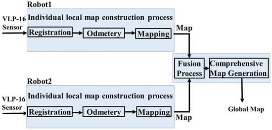
Figure 1.
Proposed system overview.
3.1. F-LOAM SLAM
A feature-based method, which builds upon point-to-edge/plane matching [11], represents an advancement over LOAM [9]. This improved version effectively conducts localization and mapping tasks with minimized computational costs (time and memory). It achieves this by employing a two-stage approach for distortion compensation, thereby circumventing the need for iterative transformations between successive laser scans that waste time and memory.
The process involves the extraction of features based on their smoothness value, which is determined using the following equation:
where pi represents the target point, and pj is in the same ring. The points with high smoothness represent the edge feature points, while the points with small smoothness represent the surface feature points, and then all features are subjected to motion distortion removal before being used in motion estimation as:
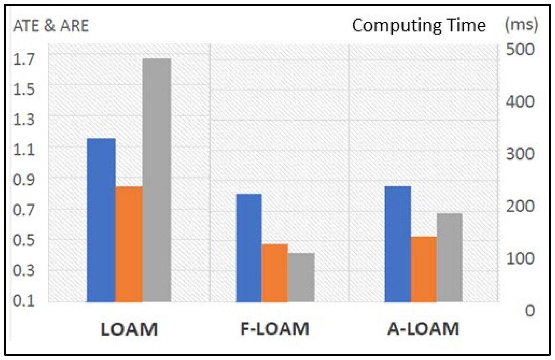
represents the current pose estimation, w represents the weights, represents the distance between the ith edge feature and the corresponding line, and represents the distance between the jth plane feature and the corresponding plane. The estimated pose is used in the second stage to recompute the undistortion features and update the final map. The FLOAM algorithm was selected for this work due to its demonstrated accuracy and performance, as shown in Figure 2.

Figure 2.
Comparison of FLOAM with LOAM and A-LOAM on KITTI dataset sequence 00–10. The orange color represents the Average Rotational Error, the blue color represents the Average Translational Error, and the gray color represents the Computing Time.
3.2. Map Fusion
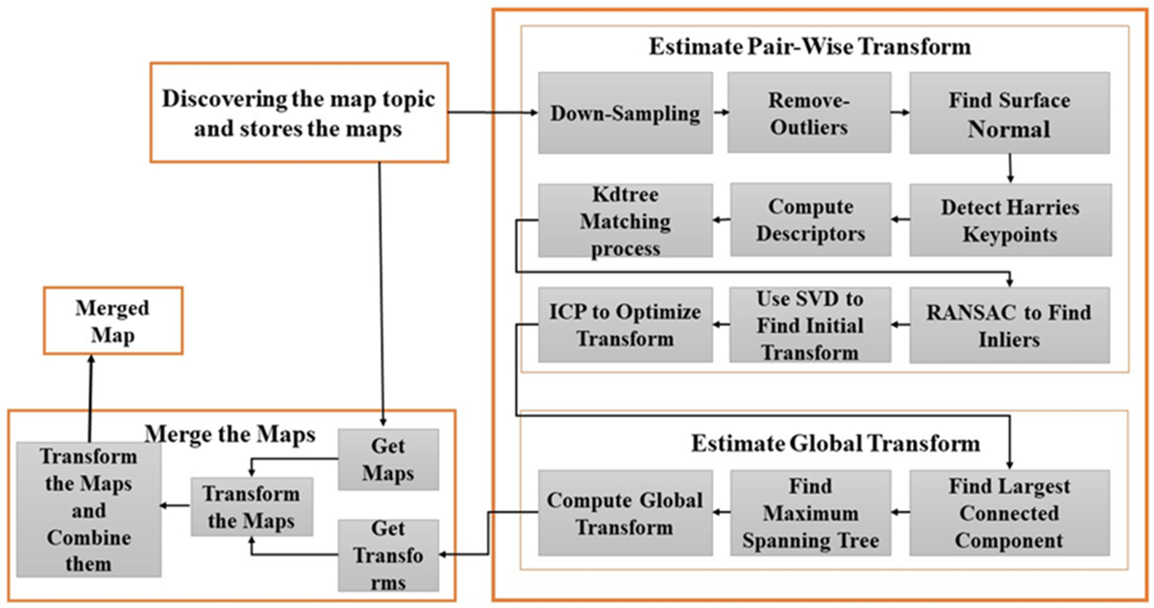
The map fusion algorithm collects the local maps and builds the 3D-global map. This can be implemented by detecting the overlapped area utilizing the feature matching technique, and then the initial transform is found among the matched features by using SVD, which is then optimized through ICP. The global transform is estimated by using a map-merging graph (“A graph whose nodes correspond to robots maps and whose edges represent pair-wise transformation estimates between the maps”). The global merged map can be computed by finding a spatial configuration of the nodes (maps) that is consistent with the transformations represented by the edges. We utilized the ROS package ‘map_merge_3d’ [24], which relies on detecting overlapping areas between the maps. Some parameters (confidence value, neighbor value) for the merged package have been modified to be compatible with F-LOAM SLAM. The algorithm is illustrated in the diagram shown in Figure 3.
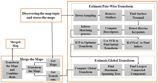
Figure 3.
Map fusion process details.
The fusion process on the central station shows three main parts:
- Discovering the Robots: This is performed by searching for all map topics in the ROS environment and then storing the maps.
- Estimate the Transform: This consists of two main parts. The first part estimates the transform between two maps, which includes the following process:
- The maps are down-sampled by using a voxal filter to reduce the computation time and deal with some noise and inaccuracies.
- Outliers are removed; this will help to remove far-lying key points.
- Surface normal is computed based on the neighborhood of the point.
- Since we deal with point cloud, which does not have color information, we should use a detector algorithm that deals with geometrical information, such as Harries 3D point detector [25]. The determined surface normal will be used to detect these points.
- Compute Fast Point Feature Histogram (FPFH) descriptors [26].
- Match the descriptors of the two maps by finding the k-nearest descriptor.
- Use Random Sample Consensus (RANSAC) [27] algorithm to find the inlier descriptors and then estimate the transform between the matched inlier descriptors by using Singular-Value Decomposition (SVD) [28].
- Align the transform with FAST_VGICP [8].
The second part relies on the node graph to estimate the transformation between the local maps and the global reference frame. This is achieved through the following steps within the match graph:
- Identification of the largest connected component, with matches having confidences less than 1.0 being discarded.
- Construction of a maximum spanning tree to select the global reference frame and provide only one path from the nodes to the selected reference.
- Determination of the global transform through the tree and pair-wise transforms.
- Merge the Maps: Obtaining the maps and their transform, then combining them to generate the 3D-global map.
The step involving transformation estimation is inherently computationally demanding and time intensive, representing a pivotal aspect of this algorithm. To tackle this concern, an efficient approach lies in the adoption of an asynchronous architecture utilizing ROS nodes.
Instead of repetitively re-estimating map transformations, a more streamlined strategy involves updating the merged map based on prior estimations. This optimization can be realized through an asynchronous map composition and transformation estimation framework. The merged node, functioning asynchronously, performs periodic map composition and transformation estimation. Specifically, the composition process can operate at high frequencies since it is already equipped with the prior transformation estimates, enabling the transformation of input maps and their subsequent concatenation. This accelerates the composition process and facilitates high update rates for the merged map, swiftly assimilating newly discovered areas.
On the other hand, the transformation estimation process, characterized by its computational intensity, operates at lower frequencies to conserve computational resources. This strategic allocation ensures that the algorithm efficiently manages computational demands while concurrently achieving a balanced trade-off between real-time responsiveness and resource optimization.
In Summary: Instead of repeatedly recalculating map transformations, the approach updates the merged map using prior estimations. This is achieved through an asynchronous framework where map composition is frequent, utilizing prior estimates, while transformation estimation, computationally intensive, occurs less often to save resources, maintaining real-time responsiveness.
4. Simulation Results
The proposed work is implemented using a laptop (Intel(R) Core(TM) i7-7500U CPU @ 2.70 GHz 2.90 GHz processor, 12.0 GB RAM, 64-bit operating system) and virtual machine software VirtualBox (Workstation Pro with four processors and 8 GB memory) to install Ubuntu 20.04 and ROS (Robotic Operating System) noetic version. First, the real-world dataset is used to compare our system with other LIDAR-based SLAM to show its performance and accuracy, and then it is implemented in a virtual environment designed by Gazebo.
- VirtualBox Software: Provides a platform for testing software, running multiple operating systems on a single machine, and developing and experimenting with various environments without affecting the host system. In our paper, we used the VirtualBox to install the Ubuntu operating system, which provides a better environment for ROS.
- Ubuntu 20.04 Operating System: A popular choice for roboticists and provides the most seamless and well-supported environment for ROS applications. Many ROS packages and libraries are built and tested primarily on Ubuntu, ensuring compatibility and stability.
- Noetic version of ROS: A preferred choice for roboticists because it offers compatibility with both Python 2 and Python 3, making it easier to transition from legacy code. It is a Long-Term Support (LTS) release with extended community support for five years, ensuring stability for long-term projects. Noetic is compatible with Ubuntu 20.04, a stable LTS operating system, and provides a migration path for existing ROS projects. Despite its Python 2 focus, it includes new features and benefits from an active community ecosystem.
- Gazebo: is a widely used simulator for robotics due to its realistic, open-source, and extensible nature. It integrates seamlessly with ROS, supports multirobot scenarios, provides accurate sensor simulation, and enjoys strong community support. This makes Gazebo an invaluable tool for developing and testing robotic systems.
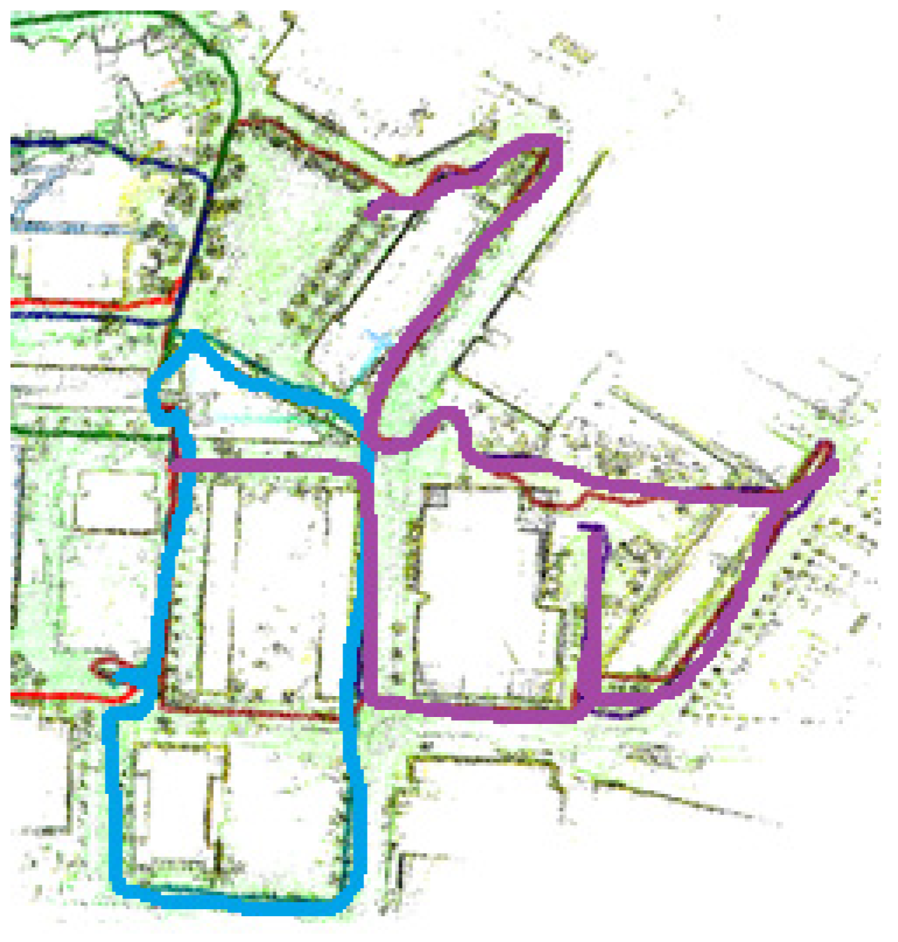
- Part 1. The method was initially assessed using a bag file dataset [29], a widely recognized benchmark for outdoor localization evaluation. The dataset originates from six robots equipped with Velodyne VLP-16 LiDAR, cameras, and GPS, which were used for driving data collection. Within our study, we focused on a subset of the dataset involving only two robots. Their respective ground truth trajectories are visualized in Figure 4, distinguished by blue and purple colors. A comprehensive breakdown of the dataset particulars can be found in Table 2.
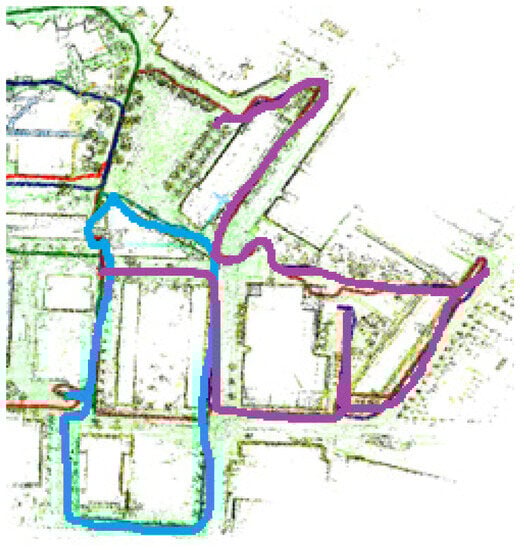 Figure 4. The ground truth trajectories for the used robots: the blue color represents robot1 path and the purple color represents robot2 path.
Table 2. The details of the used dataset in the experiment.
Figure 4. The ground truth trajectories for the used robots: the blue color represents robot1 path and the purple color represents robot2 path.
Table 2. The details of the used dataset in the experiment.
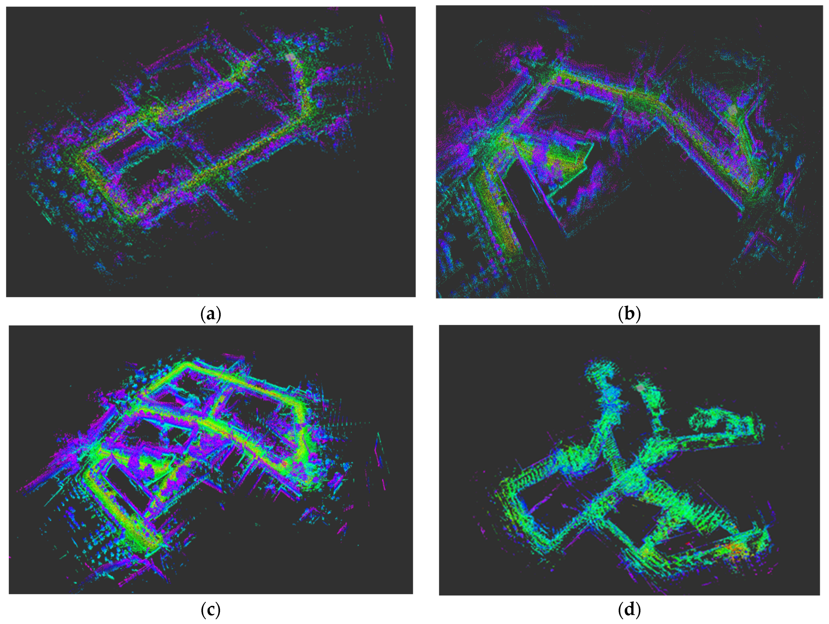
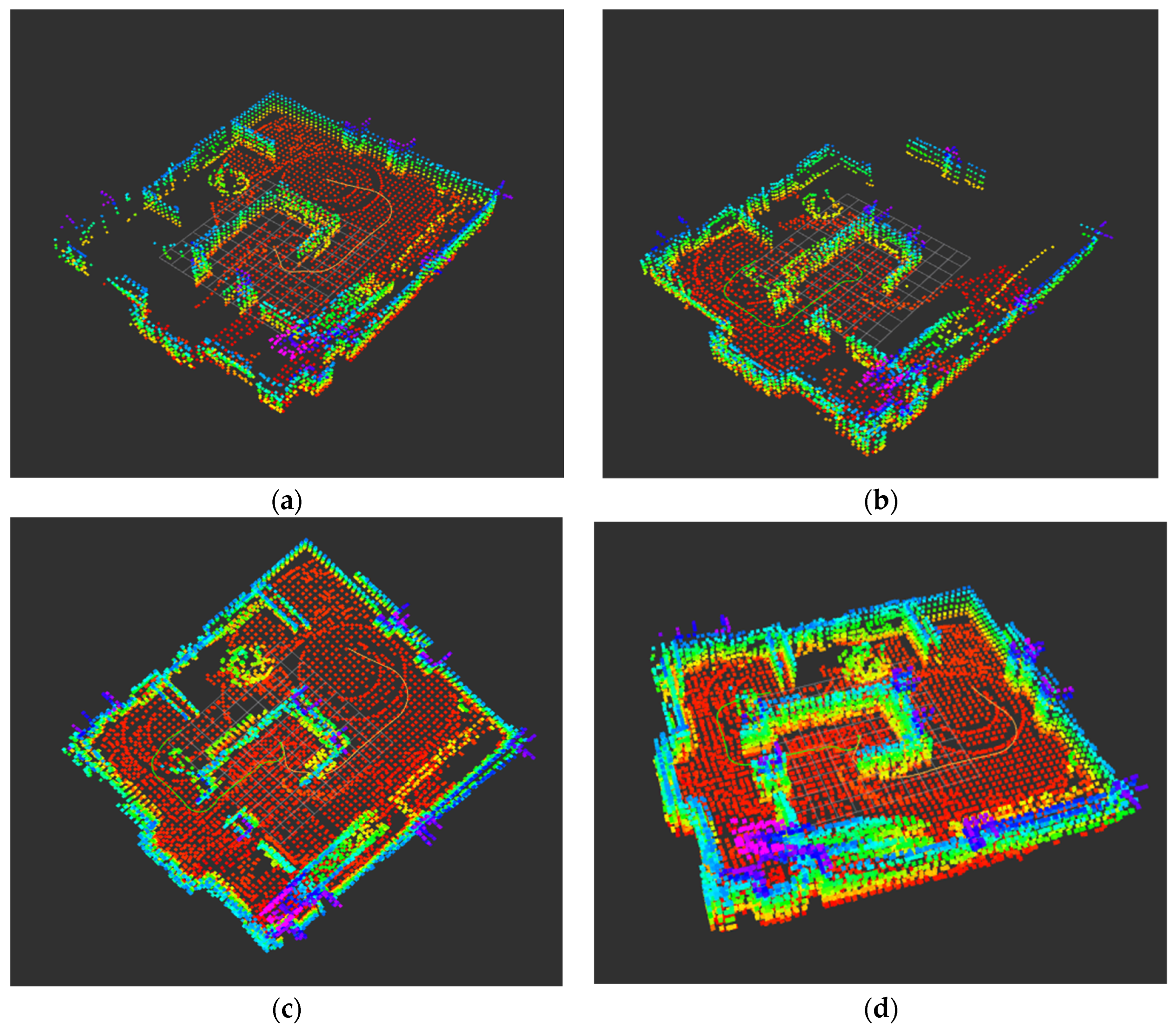
To comprehensively evaluate our proposed system, we opted to compare it with another lidar-based solution, namely A-LOAM [10]. This comparison was aimed at showcasing the effectiveness of our system. In this evaluation, both MR-ALOAM and MR-FLOAM systems were deployed, each involving two selected robots (sequences 2 and 4). Both sequences present excellent challenges to assess the effectiveness of our proposed system. Sequence 2, in particular, offers an extended path, serving as a robustness test for our system. Additionally, the second sequence includes loop closures, further enhancing the evaluation of our system’s performance. The resulting constructed maps for both systems are visually depicted in Figure 5.

Figure 5.
The maps on each robot and the final merged map: (a,b) the local maps on each robot, (c) the complete map built by MR-ALOAM, and (d) the complete map built by MR-FLOAM.
Table 3 shows the computing time (in milliseconds) for both methods, and Table 4 shows the Root Mean Square Error for each robot (RMSE); in both methods, RMSE values are calculated according to the following formula:
where (xest, yest, zest) represents the estimated pose coordinates and (xgt, ygt, zgt) represents the ground truth coordinates.
Table 3.
The computing time of both MR-FLOAM and MR-ALOAM.
Table 4.
The RMSE results for the MR-FLOAM method.
- Discussion for Part 1: MR-FLOAM notably outperforms MR-ALOAM in terms of map-matching accuracy with the ground truth path of the robots, a distinction clearly visible in Figure 5d compared to Figure 5c. This outcome highlights MR-FLOAM’s superior alignment capabilities. Furthermore, our proposed method exhibits a commendable reduction in computing time, as demonstrated in Table 3, ensuring its efficiency for real-time mapping applications.
However, the calculation of RMSE values for the robot’s path, as per the equation provided, leads to interesting observations in Table 4. Specifically, for ROBOT1 in our proposed MR-FLOAM, the RMSE value increases. This issue arises due to the absence of a loop closure detection algorithm in our system. Loop closure refers to the process of identifying and closing loops in the robot’s path within the constructed map. A loop occurs when the robot revisits a location it has previously explored during its mission. Detecting loop closure becomes particularly vital during extended operation times or in large environments, where minor errors can accumulate and lead to deviations from the robot’s actual trajectory.
The significance of loop closure detection lies in its ability to address the accumulation of pose estimation errors for ROBOT1. In the absence of this algorithm, these errors can persist and compromise the accuracy of ROBOT1’s path and map. Therefore, the implementation of a loop closure detection algorithm is pivotal for rectifying these errors and ensuring consistency within the map generated by ROBOT1.
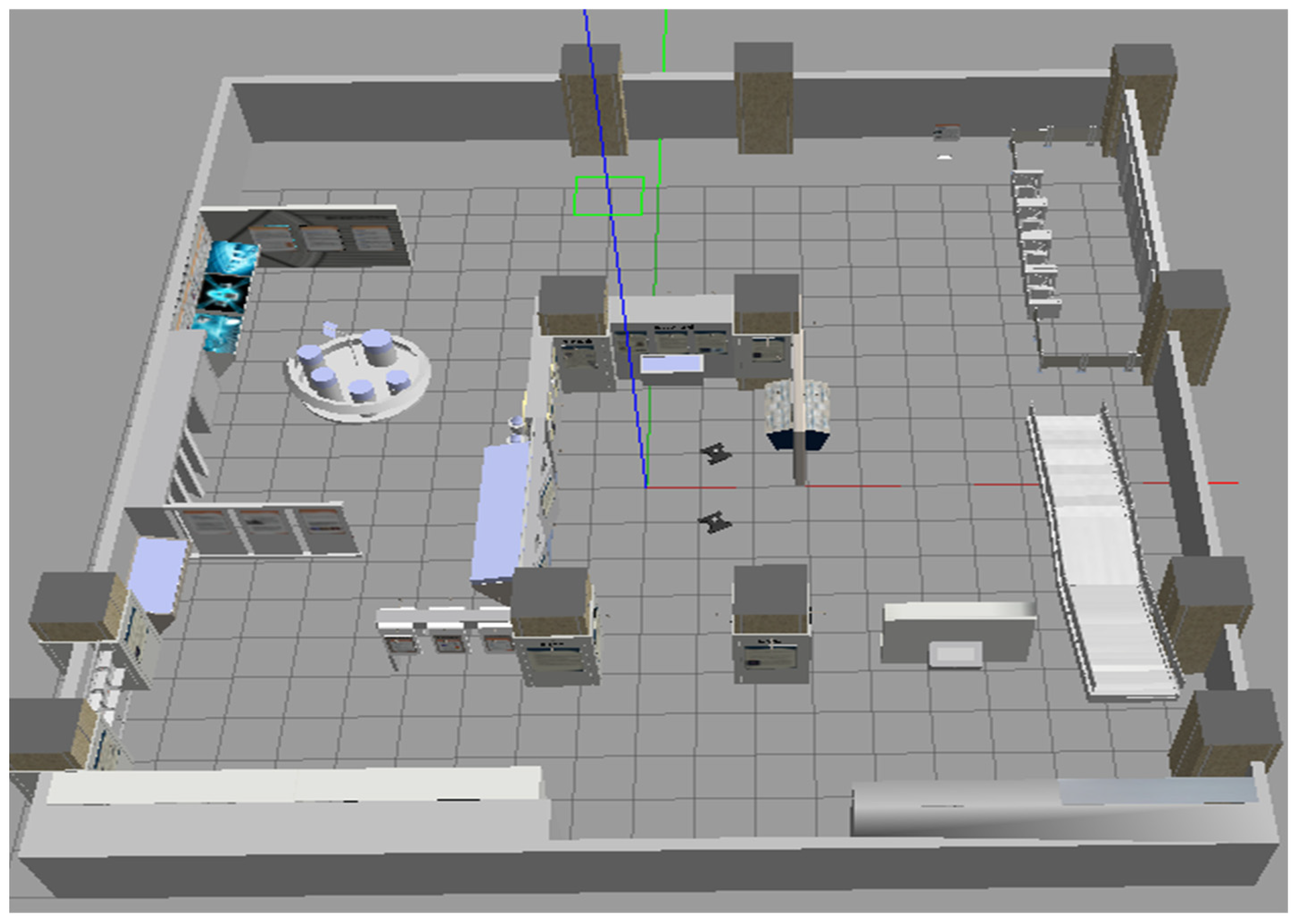
- Part 2. To implement the proposed system in a virtual environment, we used the following requirements:
- Gazebo simulator to simulate the environment, which is shown in Figure 6.
 Figure 6. Simulated museum and robots.
 - Neor_mini robot code [30]: Provides simulation for a four-wheel robot equipped with LiDAR (Velodyne-16), a camera, and a laser sensor. The two robots start to navigate through the simulated environment to build the local maps and the global map, as shown in Figure 7.
 Figure 7. The constructed maps for each robot and the final global map at the workstation: (a) and (b) the trajectory and the local map of Robot1 and Robot2, respectively; (c) the top view of the constructed global map and (d) the side view of the constructed global map.
- Discussion for Part 2: Figure 7a,b portray the partially constructed maps of individual robots. These separate maps are subsequently collated by the fusion algorithm residing at the server. The outcome of this fusion process is evident in Figure 7c,d, wherein the merged map emerges as a comprehensive depiction of the environment, culminating in a cohesive and holistic representation.
Additionally, the system excels in delivering precision pose estimation, particularly evident in indoor environments, as underscored in Table 5. This performance affirms the robustness and accuracy of our system’s pose estimation capabilities, further validating its suitability for various operational scenarios.
Table 5.
RMSE results and computing time.
5. Conclusions
We have presented a centralized MR-SLAM, where the robots construct the local maps and send them to the central station to merge the maps to create the global map. Our system utilizes the LiDAR sensor to eliminate the environmental variations that are associated with visual SLAM, which affects the robustness and accuracy of the system, as well as provides high-resolution point clouds that cover a large volumetric field of view. In addition, our system deals with computation costs by exploiting F-LOAM and map merging by using feature matching.
Integrating F-LOAM and utilizing feature-matching techniques in the fusion algorithm reduces computation time and complexity while providing a 3D map. These improvements are crucial for real-time applications, such as warehouse management and interactive guidance systems.
However, it is vital to acknowledge a notable limitation: the absence of a loop closure detection algorithm, which affects the system’s accuracy, especially in large environments. A loop closure detection algorithm is essential for reducing the accumulated pose estimation error.
Therefore, in the future, we aim to address the loop closure limitation by incorporating a loop closure detection algorithm. This algorithm will help identify loops in the robot’s path, allowing us to find the transformation between the detected loops and add it as a constraint to the pose graph for consistent map generation. As we move forward, we remain committed to advancing MR-SLAM technology, intending to make robotic mapping more efficient and precise for an array of applications by including semantic information in the map.
Author Contributions
Conceptualization, I.K.I.; methodology, B.A.J.; software, B.A.J.; formal analysis, I.K.I. and B.A.J.; validation, I.K.I. and B.A.J.; writing—original draft, B.A.J.; writing—review and editing, I.K.I.; draft preparation, B.A.J.; supervision, I.K.I. All authors have read and agreed to the published version of the manuscript.
Funding
This research received no external funding.
Data Availability Statement
Data are contained within the article.
Conflicts of Interest
The authors declare no conflict of interest.
References
- Moura, A.; Antunes, J.; Dias, A.; Martins, A.; Almeida, J. Graph-SLAM Approach for Indoor UAV Localization in Warehouse Logistics Applications. In Proceedings of the 2021 IEEE International Conference on Autonomous Robot Systems and Competitions (ICARSC), Santa Maria da Feira, Portugal, 28–29 April 2021; pp. 4–11. [Google Scholar] [CrossRef]
- Kazerouni, I.A.; Fitzgerald, L.; Dooly, G.; Toal, D. A survey of state-of-the-art on visual SLAM. Expert Syst. Appl. 2022, 205, 117734. [Google Scholar] [CrossRef]
- Debeunne, C.; Vivet, D. A Review of Visual-LiDAR Fusion based Simultaneous Localization and Mapping. Sensors 2020, 20, 2068. [Google Scholar] [CrossRef]
- Cunha, F.; Youcef-Toumi, K. Ultra-Wideband Radar for Robust Inspection Drone in Underground Coal Mines. In Proceedings of the 2018 IEEE International Conference on Robotics and Automation (ICRA), Brisbane, Australia, 21–25 May 2018; pp. 86–92. [Google Scholar] [CrossRef]
- Milz, S.; Arbeiter, G.; Witt, C.; Abdallah, B.; Yogamani, S. Visual SLAM for Automated Driving: Exploring the Applications of Deep Learning. In Proceedings of the IEEE Computer Society Conference on Computer Vision and Pattern Recognition Workshops, Salt Lake City, UT, USA, 18–23 June 2018; Volume 2018-June, pp. 360–370. [Google Scholar] [CrossRef]
- Ito, S.; Hiratsuka, S.; Ohta, M.; Matsubara, H.; Ogawa, M. Small Imaging Depth LIDAR and DCNN-Based Localization for Automated Guided Vehicle. Sensors 2018, 18, 177. [Google Scholar] [CrossRef] [PubMed]
- Li, R.; Liu, J.; Zhang, L.; Hang, Y. LIDAR/MEMS IMU integrated navigation (SLAM) method for a small UAV in indoor environments. In Proceedings of the 2014 DGON Inertial Sensors and Systems (ISS), Karlsruhe, Germany, 16–17 September 2014; pp. 18–32. [Google Scholar]
- Besl, P.J.; McKay, N.D. A method for registration of 3-D shapes. IEEE Trans. Pattern Anal. Mach. Intell. 1992, 14, 239–256. [Google Scholar] [CrossRef]
- Zhang, J.; Singh, S. Low-drift and real-time lidar odometry and mapping. Auton. Robot. 2017, 41, 401–416. [Google Scholar] [CrossRef]
- Gonzalez, C.; Adams, M. An improved feature extractor for the Lidar Odometry and Mapping (LOAM) algorithm. In Proceedings of the 2019 International Conference on Control, Automation and Information Sciences (ICCAIS), Chengdu, China, 23–26 October 2019; pp. 1–7. [Google Scholar] [CrossRef]
- Wang, H.; Wang, C.; Chen, C.-L.; Xie, L. F-LOAM: Fast LiDAR Odometry and Mapping. In Proceedings of the IEEE/RSJ International Conference on Intelligent Robots and Systems (IROS), Prague, Czech Republic, 27 September–1 October 2021; pp. 4390–4396. [Google Scholar] [CrossRef]
- Li, L.; Kong, X.; Zhao, X.; Li, W.; Wen, F.; Zhang, H.; Liu, Y. SA-LOAM: Semantic-aided LiDAR SLAM with Loop Closure. In Proceedings of the 2021 IEEE International Conference on Robotics and Automation (ICRA), Xi’an, China, 30 May–5 June 2021; pp. 7627–7634. [Google Scholar] [CrossRef]
- Kishimoto, Y.; Takaba, K.; Ohashi, A. Moving Horizon Multi-Robot SLAM Based on C/GMRES Method. In Proceedings of the International Conference on Advanced Mechatronic Systems (ICAMechS), Kusatsu, Japan, 26–28 August 2019. [Google Scholar]
- Chang, Y.; Tian, Y.; How, J.P.; Carlone, L. Kimera-Multi: A System for Distributed Multi-Robot Metric-Semantic Simultaneous Localization and Mapping. In Proceedings of the 2021 IEEE International Conference on Robotics and Automation (ICRA), Xi’an, China, 30 May–5 June 2021; pp. 11210–11218. [Google Scholar] [CrossRef]
- Lajoie, P.Y.; Beltrame, G. Swarm-SLAM: Sparse Decentralized Collaborative Simultaneous Localization and Mapping Framework for Multi-Robot Systems. arXiv 2023, arXiv:2301.06230. [Google Scholar]
- Schmuck, P.; Chli, M. CCM-SLAM: Robust and efficient centralized collaborative monocular simultaneous localization and mapping for robotic teams. J. Field Robot. 2019, 36, 763–781. [Google Scholar] [CrossRef]
- Boroson, E.R.; Hewitt, R.; Ayanian, N.; de la Croix, J.-P. Inter-Robot Range Measurements in Pose Graph Optimization. In Proceedings of the 2020 IEEE/RSJ International Conference on Intelligent Robots and Systems (IROS), Las Vegas, NV, USA, 25–29 October 2020; pp. 4806–4813. [Google Scholar] [CrossRef]
- Liu, W. Slam algorithm for multi-robot communication in unknown environment based on particle filter. J. Ambient. Intell. Humaniz. Comput. 2021, 1–9. [Google Scholar] [CrossRef]
- Chen, Y.; Wang, Y.; Lin, J.; Chen, Z.; Wang, Y. Multi-Robot Point Cloud Map Fusion Algorithm Based on Visual SLAM. In Proceedings of the 2021 IEEE International Conference on Consumer Electronics and Computer Engineering (ICCECE), Guangzhou, China, 15–17 January 2021; pp. 329–333. [Google Scholar] [CrossRef]
- Chang, Y.; Ebadi, K.; Denniston, C.E.; Ginting, M.F.; Rosinol, A.; Reinke, A.; Palieri, M.; Shi, J.; Chatterjee, A.; Morrell, B.; et al. LAMP 2.0: A Robust Multi-Robot SLAM System for Operation in Challenging Large-Scale Underground Environments. IEEE Robot. Autom. Lett. 2022, 7, 9175–9182. [Google Scholar] [CrossRef]
- Ye, K.; Dong, S.; Fan, Q.; Wang, H.; Yi, L.; Xia, F.; Wang, J.; Chen, B. Multi-Robot Active Mapping via Neural Bipartite Graph Matching. In Proceedings of the 2022 IEEE/CVF Conference on Computer Vision and Pattern Recognition (CVPR), New Orleans, LA, USA, 18–24 June 2022; pp. 14819–14828. [Google Scholar] [CrossRef]
- Kshirsagar, J.; Shue, S.; Conrad, J.M. A Survey of Implementation of Multi-Robot Simultaneous Localization and Mapping. In Proceedings of the SoutheastCon 2018, St. Petersburg, FL, USA, 19–22 April 2018; IEEE: Washington, DC, USA, 2018. [Google Scholar]
- Saeedi, S.; Trentini, M.; Seto, M.; Li, H. Multiple-robot simultaneous localization and mapping: A review. J. Field Robot. 2016, 33, 3–46. [Google Scholar] [CrossRef]
- Hörner, J. Automatic Point Clouds Merging. Master’s Thesis, Faculty of Mathematics and Physics, Charles University, Prague, Czech Republic, 2018. [Google Scholar]
- Harris, C.; Stephens, M. A Combined Corner and Edge Detector. In Proceedings of the AVC, Manchester, UK, 31 August–2 September 1988. [Google Scholar]
- Rusu, R.B.; Blodow, N.; Beetz, M. Fast Point Feature Histograms (FPFH) for 3D registration. In Proceedings of the 2009 IEEE International Conference on Robotics and Automation, Kobe, Japan, 12–17 May 2009; pp. 3212–3217. [Google Scholar]
- Fischler, M.A.; Bolles, R.C. Random sample consensus: A Paradigm for Model Fitting with Applications to Image Analysis and Automated Cartography. Commun. ACM 1981, 24, 381–395. [Google Scholar] [CrossRef]
- Golub, G.H.; Reinsch, C. Singular value decomposition and least squares solutions. Numer. Math. 1970, 14, 403–420. [Google Scholar] [CrossRef]
- Tian, Y.; Chang, Y.; Quang, L.; Schang, A.; Nieto-Granda, C.; How, J.P.; Carlone, L. Resilient and Distributed Multi-Robot Visual SLAM: Datasets, Experiments, and Lessons Learned. In Proceedings of the IEEE Computer Society Conference on Computer Vision and Pattern Recognition Workshops, Salt Lake City, UT, USA, 18–23 June 2018. [Google Scholar]
- Neor_Mini Ackerman Mobile Base. Available online: https://github.com/COONEO/neor_mini (accessed on 3 March 2021).

Disclaimer/Publisher’s Note: The statements, opinions and data contained in all publications are solely those of the individual author(s) and contributor(s) and not of MDPI and/or the editor(s). MDPI and/or the editor(s) disclaim responsibility for any injury to people or property resulting from any ideas, methods, instructions or products referred to in the content. |
© 2023 by the authors. Licensee MDPI, Basel, Switzerland. This article is an open access article distributed under the terms and conditions of the Creative Commons Attribution (CC BY) license (https://creativecommons.org/licenses/by/4.0/).