Article

The Impact of Clock Frequencies on Remote Power Side-Channel Analysis Attack Resistance of Processors in Multi-Tenant FPGAs

by
Qinming Zhou
,
Haozhi Xie
and
Tao Su
*
School of Electronics and Information Technology (School of Microelectronics), Sun Yat-sen University, Guangzhou 510006, China
*
Author to whom correspondence should be addressed.
Cryptography 2025, 9(1), 15; https://doi.org/10.3390/cryptography9010015
Submission received: 31 December 2024 / Revised: 20 February 2025 / Accepted: 28 February 2025 / Published: 3 March 2025
(This article belongs to the Special Issue Emerging Topics in Hardware Security)

Abstract

:
Field-programmable gate arrays (FPGAs) are widely used in cloud servers as an acceleration solution for compute-intensive tasks. Cloud FPGAs are typically multi-tenant, enabling resource sharing among multiple users but are vulnerable to power side-channel analysis (SCA) attacks due to their programmability and runtime dynamic reconfigurability. It is well-known that the clock frequencies of the circuits on multi-tenant FPGAs affect power consumption, but their impact on remote correlation power analysis (CPA) attacks has largely been ignored in the literature. This work systematically evaluates how clock frequency variations influence the effectiveness of remote CPA attacks on multi-tenant FPGAs. We develop a theoretical model to quantify this impact and validate our findings through the CPA attacks on processors running AES-128 and SM4 cryptographic algorithms. Our results demonstrate that the runtime clock frequency significantly affects the performance of remote CPA attacks. Our work provides valuable insights into the security implications of frequency scaling in multi-tenant FPGAs and offers guidance on selecting clock frequencies to mitigate power side-channel risks.

1. Introduction

With the advancement of cloud computing services, field-programmable gate arrays (FPGAs) have been widely deployed in cloud servers due to hardware parallelism and dynamic reconfigurability. Cloud FPGAs are widely used in cloud servers, to implement computation acceleration, such as machine learning, financial analytics, security, and video processing. Cloud FPGAs are generally multi-tenant to maximize resource utilization, enabling multiple users to share a single FPGA chip physically, while maintaining logical isolation. Since tenants share the power distribution networks (PDNs) of an FPGA in the cloud, the power side-channel presents a potential attack surface for malicious attackers. Attackers can leverage the programmable logic of the FPGA to implement power sensors, monitor the power consumption related to sensitive data computations within the victim’s circuit, and subsequently extract confidential information. As power side-channel attacks leverage data-dependent changes in power consumption, the dynamic power consumption generated by transistor switching is mainly exploited [1]. In multi-tenant FPGAs, attackers commonly deploy time-to-digital converters (TDCs) or ring oscillators (ROs) to monitor transient power fluctuations on the FPGA chip at high sampling rates, allowing them to infer the victim’s private information [2,3,4,5].
Additionally, in multi-tenant FPGAs, where attackers can not only monitor the PDN but also manipulate it to induce malicious voltage drops by power plundering circuits (e.g., RO), causing timing violations and subsequent faults in the circuits to reveal confidential information [6,7,8].
In previous studies, to prevent timing violations caused by voltage drops on the PDN, static frequency scaling (SFS) [5] and dynamic frequency scaling (DFS) [5,9] frameworks were applied. The SFS framework calculates the safe clock frequency based on the maximum delay difference caused by voltage drop and executes the circuits at a conservatively low clock frequency. The DFS framework dynamically scales the circuit clock frequency based on real-time voltage measurements and passively executes the victim circuit at a lower clock frequency. However, in multi-tenant FPGAs, computationally intensive workloads cause significant voltage drops due to the rapid switching of a large number of logic gates. Since these workloads are not instantaneous and often exhibit prolonged execution times, the circuit may operate at a reduced clock frequency for an extended duration. This may unexpectedly introduce new vulnerabilities to power side-channel analysis attacks. Therefore, our study aims to investigate the vulnerabilities introduced by frequency scaling to remote correlation power analysis attacks on multi-tenant FPGAs.
Reference [10] proposed a tunable dual-polarity TDC, introducing the following three dynamically adjustable parameters: transition polarity, sample window, frequency, and phase. Utilizing this tunable bipolar TDC as a power monitoring sensor on multi-tenant FPGAs for CPA attacks improved the ranking of the correct sub-key value by 2×.
By adjusting the transition polarity, sample window, frequency, and phase of the TDC, the moments when the victim circuit’s power consumption reaches its maximum can be more frequently exposed within the sampling points of the TDC. Similarly, for an unadjusted TDC, reducing clock frequency in the victim circuit may increase the occurrence of power consumption peaks within the TDC’s sampling points, thereby increasing the risk of correlation power analysis attacks.
The contributions of this paper are the following:
  • To the best of our knowledge, we present the first theoretical analysis of unintended power side-channel leakage caused by changes in the victim circuit’s clock frequency.
  • We characterize the performance of CPA with varying clock frequencies and phase relationships between the victim circuit and the TDC of an attacker using three metrics. The results confirm that a successful CPA attack requires fewer power traces when there is a specific relationship between phase and frequency.
  • We present the CPA attack results of the AES-128 and SM4 algorithms on a Cortex-M0 operating at different clock frequencies to validate our theoretical analysis. Our study investigates the side-channel leakage phenomena of general-purpose processors on FPGAs when dynamically changing the clock frequencies.
The rest of the paper is organized as follows. The background is briefly explained in Section 2. Section 3 presents a theoretical analysis of unintended power side-channel leakage caused by the victim’s clock frequency changes. The experimental setup is presented in Section 4.1. Section 4 characterizes clock frequency and the phase relationships between the victim circuit and the TDC, and the CPA results are presented. The research limitations of this work and future developments are discussed in Section 5. The paper is concluded in Section 6.

2. Background

2.1. Threat Model of Multi-Tenant FPGAs

We adopt the widely accepted threat model described in numerous studies on electrical-level threats in multi-tenant FPGAs [11,12,13], as depicted in Figure 1. In this model, attackers can program an arbitrary design in a partial region of an FPGA shared with at least one victim user. There are no logic or clock signal connections between FPGA tenants, and each tenant has its own clock resource. We assume the victim utilizes their portion of the programmable logic for a security-related algorithm, such as a block cipher. The attacker and the victim are logically isolated on FPGA; they can only access the public resources on multi-tenant FPGAs, such as external I/O. Consequently, the remaining connections are facilitated through PDNs, making all possible attack surfaces side-channels.
The PDN can be equivalently modeled as an RLC network, where switching activity on the chip induces variations in the supply current, leading to voltage fluctuations within the PDN [14]. Other tenants sharing the same FPGA chip can also perceive these variations in the supply voltage, posing both reliability and security issues in FPGA multi-tenancy. The attacker is assumed to use FPGA logic to integrate a sensor that records side-channel information, such as voltage fluctuations, which can be analyzed to extract secret keys from cryptographic circuits implemented on the FPGA.

2.2. Voltage-Drop Sensors

Generally, RO and TDC are two types of voltage-drop sensors deployed on multi-tenant FPGAs [2,3,4,15,16]. The principle of both TDC and RO-based sensors is circuit delay, which is proportional to the supply voltage. Therefore, the change of sensor logic delay reflects the voltage fluctuation of victim circuits, which is relevant to the switching activity induced by manipulated data.
On FPGAs, ROs are typically constructed using look-up tables (LUTs), while TDCs are formed using delay lines built by cascaded CARRY4. The choice between RO-based and TDC-based voltage sensors primarily depends on sampling accuracy and voltage sensitivity. RO-based sensors are easier to implement but have lower sensitivity to instantaneous voltage changes and require longer sampling times. Conversely, TDC-based sensors can achieve higher sampling rates and exhibit greater sensitivity to instantaneous voltage changes, as the carry chains are more sensitive to delays caused by voltage drops [17]. For hardware acceleration, the circuits running on multi-tenant FPGAs typically operate at high clock frequencies. Thus, TDCs are commonly selected as sensors to measure transient voltage changes on multi-tenant FPGAs.
The schematic of the TDC-based delay sensor is shown in Figure 2. The TDC-based delay sensor features the following two input clocks: one drives the delay line, and the other samples the D flip-flops (DFFs) connected to the outputs of the delay line. These clocks typically operate at a high frequency and have a phase difference θ , which is used to calibrate the outputs. The output range of the TDC sensor is adjustable and is referred to as the observed delay line. The direct output of the TDC is a binary vector of the propagation speed, which contains different numbers of consecutive zeros and ones, and needs an encoder to convert it as a readable output. For example, in our design shown in Figure 2, the TDC length is 160, with each set of four binary outputs corresponding to one encoder. Moreover, the final output is the sum of the outputs of 40 encoders. The 40 encoders convert the 160-bit input into a readable 8-bit integer output. This vector of the propagation speed is captured as a discrete-time signal, referred to as a power trace, and can be analyzed to infer confidential information from the circuit.

2.3. Correlation Power Analysis Attack

In 2004, reference [18] proposed the CPA attacks based on Pearson’s correlation coefficient, which is an efficient technique to extract the key of the cipher.
Measuring the power traces of cipher hardware running with different plaintext is necessary for CPA attacks. Let P denote the number of collected power traces and T denote the length of each power trace. For CPA attacks, the raw data of the collected power traces can be represented as a matrix O of size P × T . The steps of CPA attacks are as follows:
  • Select an appropriate intermediate value v that must be related to both the confidential information and the known input plaintext. The choice of v depends on the targeted encryption algorithm and the leakage characteristics of the target hardware implementation. For the AES algorithm, commonly used intermediate values in CPA attacks are the output of the first round AddRoundKey or the first output of the S-box.
  • Compute the intermediate values for all possible keys k, based on the corresponding input plaintext p, to generate an intermediate value matrix V of size K × P .
  • Choose an appropriate power model and compute the hypothetical power consumption matrix H for the intermediate value matrix V. Common power models include the Hamming weight (HW) model and the Hamming distance (HD) model. For example, for recovering byte 0 of the AES first round key using the S-box output as intermediate values, the element h of the hypothetical power consumption matrix H can be expressed as follows:
    h p k = H W ( S B o x ( b p 0 k )
    where b p 0 is byte 0 of the plaintext p, and H W denotes the Hamming weight.
  • Calculate the Pearson correlation coefficient between the hypothetical power consumption matrix H and the observed power consumption matrix O, resulting in a correlation coefficient matrix R of size K × T . Each element r k , t can be expressed as Equation (2), where t p , t represents the value of the t-th sample point in the power trace corresponding to the plaintext p.
    r k , t = p = 0 P 1 ( h p , k h k ¯ ) ( t p , t t t ¯ ) p = 0 P 1 ( h p , k h k ¯ ) 2 p = 0 P 1 ( t p , t t t ¯ ) 2
  • Rank all possible keys k based on the magnitude of their correlation coefficients, with the key having the highest correlation coefficient being ranked first as the guessed key.

3. Theoretical Analysis of Clock Frequency Impact on the Power Side-Channel

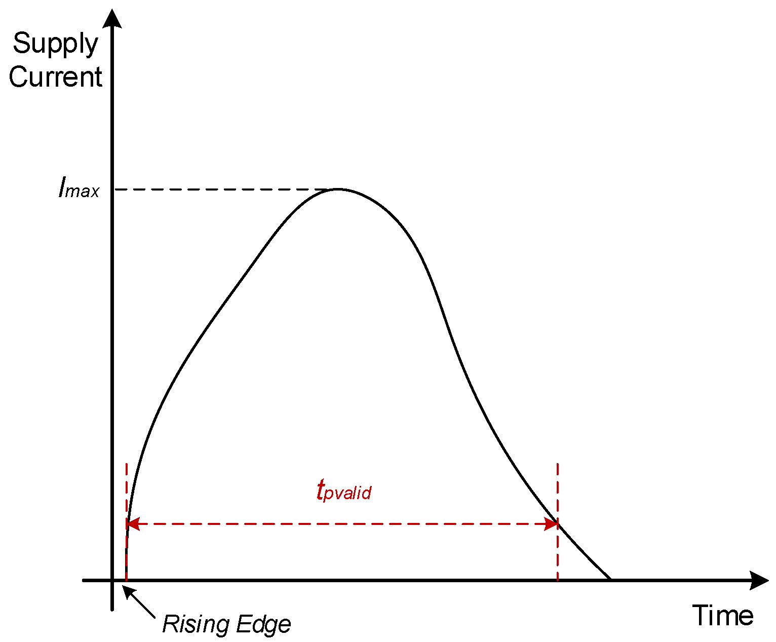
3.1. Power Side-Channel

In CMOS circuits, dynamic power is the primary source of power consumption and is related to the secret data processed by the circuits, making it exploitable as a side-channel. The power side-channel analysis attack aims to extract specific confidential information by analyzing the data-dependent power consumption of a cryptographic implementation. The dynamic power of the CMOS circuit is expressed as Equation (3), consisting of switching power consumption P s w and short-circuit power consumption P s c [19,20]. α , C, V D D , f, I p e a k , and t s c represent the switching activity factor, load capacitance, supply voltage, clock frequency, peak current and shortcut-circuit time, respectively.
P d y n = P s w + P s c = α · C · V D D 2 · f + V D D · I p e a k · t s c · f
As shown in Figure 3, after the rising edge of the clock, the supply current from the PDN to the circuit reaches its maximum, which will cause detectable voltage fluctuations on the PDN [21]. Attackers usually sample power consumption at a fixed sampling frequency. Therefore, whether the sampling point overlaps with the time window of detectable voltage fluctuations, t p v a l i d , will greatly influence the quality of the power trace. When the sampling point overlaps with t p v a l i d , the power consumption that can be used for power analysis attacks in the power trace accounts for a large proportion. It can be considered that the signal-to-noise ratio of the power trace is high at this time, leading to the improvement of the CPA attack performance. Next, we will quantitatively analyze the factors that affect the quality of the power trace.

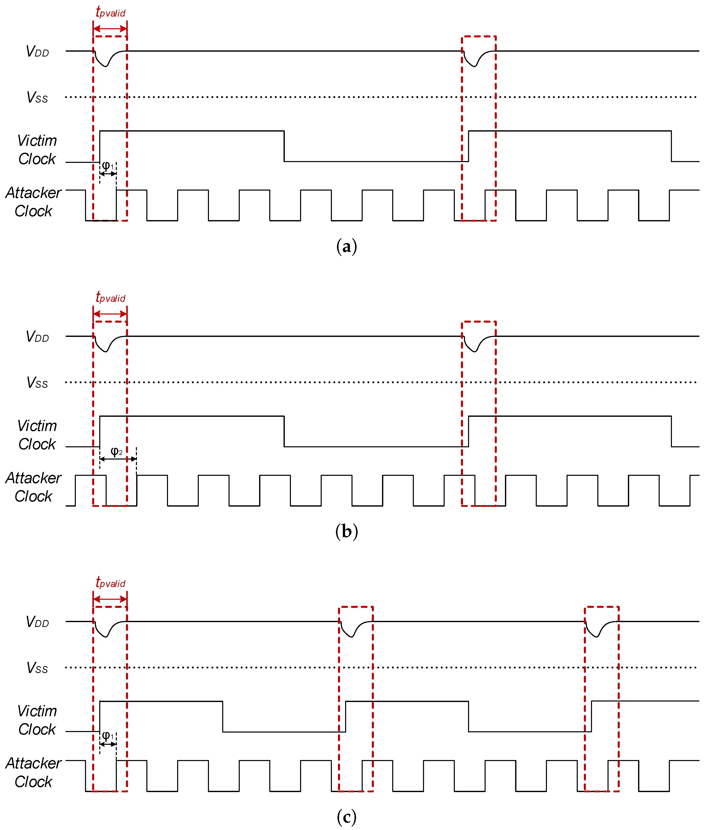
3.2. Mechanism of Clock Frequency Impact

To explain how changes in the clock frequency of the victim circuit affect the performance of the CPA attack, we assume the attacker collects power traces at a fixed sampling frequency, given that the attacker lacks knowledge of the victim’s clock phase or frequency. Typically, circuits on cloud FPGAs employ timing elements sensitive to rising clock edges. When the victim circuit’s clock is at a rising edge, the logic gates switch, causing significant current changes, leading to detectable voltage fluctuations in the PDN. Consequently, if the attacker’s sampling points align with the victim circuit’s clock-rising edge, the power sensor can detect more apparent voltage fluctuations.
As shown in Figure 4, we denote the phase difference between the attacker’s sampling clock and the victim’s runtime clock as ϕ . The attacker’s sampling clock frequency is F Attacker , and the victim circuit’s runtime clock frequency is F Victim . The positions of rising edges of the victim’s runtime clock can then be expressed by Equation (4), where n is a non-negative integer.
t v i c t i m ( n ) = n F Victim
The attacker’s sampling point can be described by Equation (5), where m is also a non-negative integer.
t a t t a c k e r ( m ) = m F Attacker + ϕ ,   ϕ π , π
The current variations and voltage fluctuations on the PDN last for a duration. If the attacker’s sampling points coincide with this time window, they can still detect significant voltage fluctuations. We define the time window of a detectable power consumption change on the PDN as t p v a l i d . Thus, when the attacker’s sampling point meets Equation (6), this sample point is effective for power analysis attacks, referred to as a valid sample point.
Δ = n F Victim m F Attacker + ϕ ,   Δ [ 0 , t pvalid ] ,   n , m N
As illustrated in Figure 4a,c, when the phase difference ϕ 1 between the attacker’s clock and the victim circuit’s clock is small, increasing the victim circuit’s clock frequency raises the proportion of valid sample points among all sample points, making extracting useful information easier for CPA attacks. Conversely, as depicted in Figure 4a,b, the large phase difference ϕ 2 can cause the attacker’s sampling clock to fall outside the PDN voltage fluctuation window, making it harder to extract information from power traces.
Since the current variations are maximal near clock-rising edges of victim circuits, the information of the valid sample points provided to power analysis attacks varies, as shown in Figure 3. To characterize this effect, we apply a weighted average to derive the effective power quantity (EPQ). The weight w p of the effective power within t pvalid is modeled as decreasing linearly with the time difference between the attacker’s sample point and the victim circuit’s clock-rising edge, as expressed in Equation (7).
w p = 1 Δ t pvalid
Thus, EPQ can be expressed as Equation (8), where M is the total number of sample points in a power trace.
E P Q = m M w p M
To further validate our theory, we conduct CPA attacks to extract the keys of the AES and SM4 algorithms running on a Cortex-M0 softcore.

4. Results and Analysis

4.1. Experimental Setup

Our experimental platform is the Zedboard with Xilinx Aritx-7 FPGA (xc7z020clg484-1) and a ZCU102 board with a Xilinx Zynq UltraScale+ FPGA (xczu9eg-2ffvb1156-2-e).
The victim circuit is an ARM Cortex-M0 running block cipher algorithm. We utilize the open source netlist format RTL code of the ARM Cortex-M0 to implement it on FPGA. In our experiments on cryptographic algorithms, we evaluated two types of block ciphers, AES-128 and SM4, selecting the output of the first-round SBox as the attack point. We choose the HW model as our power consumption model. The target of CPA attacks is to extract the round key of the first round. For the AES algorithm, denote the sub-key as k i , the byte i of plaintext as b p i , and the SBox operation as S b o x ( ) . The hypothesis power consumption of AES is expressed in Equation (9).
h p k = H W ( S b o x ( b p i k i ) )
For the SM4 algorithm, because the first round does not involve the first byte of the plaintext, we set the first byte of the plaintext to zero, which is commonly used to improve the efficiency of attacking the SM4 algorithm [22]. Thus, the hypothesis power consumption for the SM4 algorithm is described by Equation (10).
h p k = H W ( S b o x ( b p 1 b p 2 b p 3 k i ) )
To avoid the impact of re-layout and routing on the clock, we utilized the dynamic reconfiguration capability of the Xilinx clock management tile (CMT) to adjust the frequency of the victim circuit and the TDC sampling clock frequency [23]. Each Xilinx CMT includes a mixed-mode clock manager (MMCM) and a phase-locked loop (PLL), and we utilize the MMCM to implement dynamic reconfiguration. For multi-tenant FPGAs, there is usually a common global clock, and then the clock is distributed to each tenant through interconnection [24]. In our experiment, F V i c t i m and F A t t a c k e r are derived from the same common base clock, which is in line with the general scenario on cloud FPGAs.
We used the same encryption key and randomized plaintext to ensure consistency across experiments. A 160-bit TDC sensor (observable delay lines with 160 elements) was used to record the power traces of the Cortex-M0 running at different clock frequencies. For Zedboard with Artix-7 FPGA, we applied four TDC sensors. For ZCU102 with Zynq UltraScale+ FPGA, we applied 16 TDC sensors. To reduce the noise, we average the power traces collected by multiple TDC sensors and average every 10 collected power traces as the final power trace.
To explore the impact of F V i c t i m , ϕ and F A t t a c k e r , we designed three sets of comparative experiments. The experimental conditions are shown in Table 1.
In the first experimental setup, we consider a typical CPA attack scenario where the attacker collects power traces at a fixed sampling rate. Concurrently, the victim operates at a constant clock frequency. A random phase difference ϕ exists between the victim’s clock and the attacker’s sampling clock. The phase alignment function of the CMTs is not enabled in this experiment, so the two clocks have a random phase difference when powered on. In the second set of experiments, the phase difference ϕ between the clock of the attacked circuit and the attacker’s sampling clock is 0. The attacker collects power traces at a constant sampling rate while the victim operates at a fixed frequency to assess the impact of frequency on CPA attacks. In the final experiment, we maintain a zero phase difference but keep the sampling rate to five times the constant F V i c t i m to further analyze its effect on CPA attacks.

4.2. CPA Evaluation Metrics

Following prior work, we employ multiple metrics to analyze the results of the CPA attack. The CPA attack sorts the sub-keys of the block cipher according to the correlation coefficient to obtain the most likely key value. To quantify the performance of the CPA attack from all aspects, we use the three most commonly used indicators, guessing entropy (GE), partial success rate (PSR), and minimum traces for disclosure (MTD) [25,26,27,28].
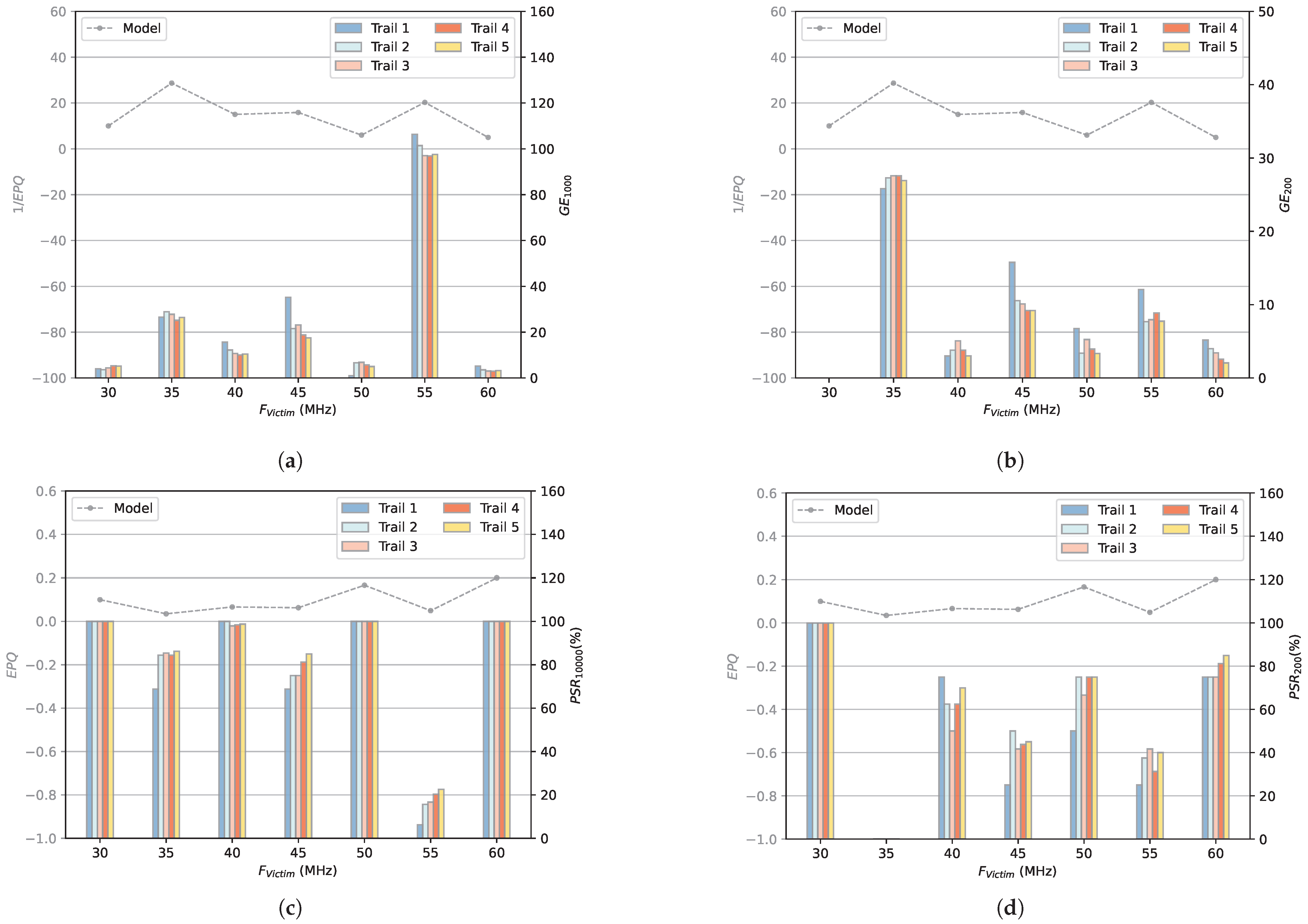
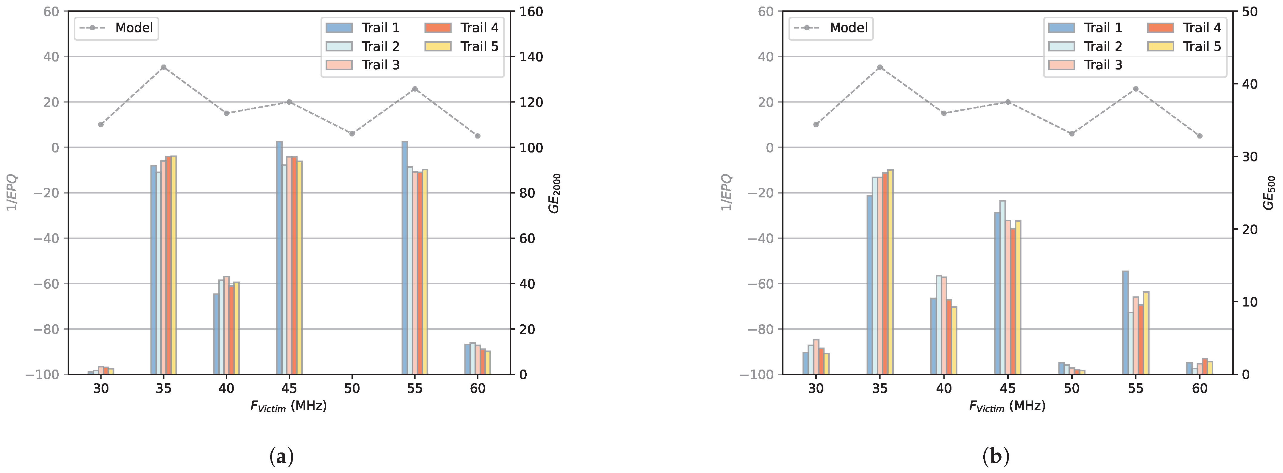
  • GE: GE is an indicator based on the correlation coefficient matrix R. For byte i of the round key (referred to as sub-key k i ), all possible key byte guesses are ordered by their correlation coefficient in descending order to determine the rank of the correct key byte. The ranks for all correct key bytes are then summed logarithmically to calculate the GE, as illustrated in Equation (11). We use t to indicate the number of traces used to calculate this GE.
    G E t = i = 1 K l o g 2 [ r a n k ( k i c o r r e c t _ k e y ) ]
    A lower GE signifies lower average ranks across all key bytes, typically indicating that more key bytes have been successfully recovered. A GE value of 0 means that all key bytes have been recovered. In practice, a CPA attack is considered successful if the GE value falls below a predefined threshold, enabling the recovery of key bytes with reasonable computational effort. It should be noted that a low GE value does not guarantee the correct sub-key ranks first, as erroneous sub-keys may still be present. Thus, GE is not a reliable metric for assessing CPA attack performance in recovering all sub-keys. Only GE = 0 indicates full sub-key recovery.
  • PSR: We also use the PSR calculated as Equation (12) to evaluate the effectiveness of CPA attacks in recovering the sub-keys.
    P S R t = N i c k N t o t a l × 100 %
    In Equation (12), N i c k denotes the number of correctly estimated sub-keys using i traces. N t o t a l denotes the number of total sub-keys. We use t to indicate the number of traces used to calculate this PSR. For example, P S R 20 , 000 = 100 % means that all sub-keys are correctly retrieved using 20,000 traces.
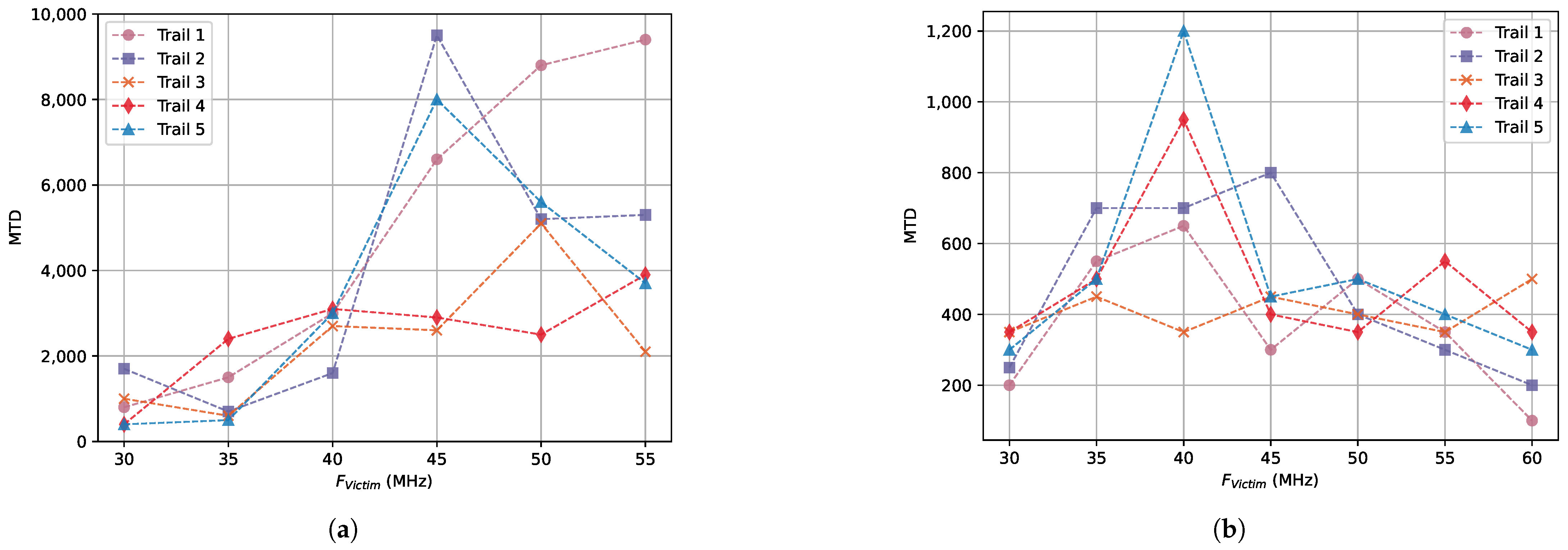
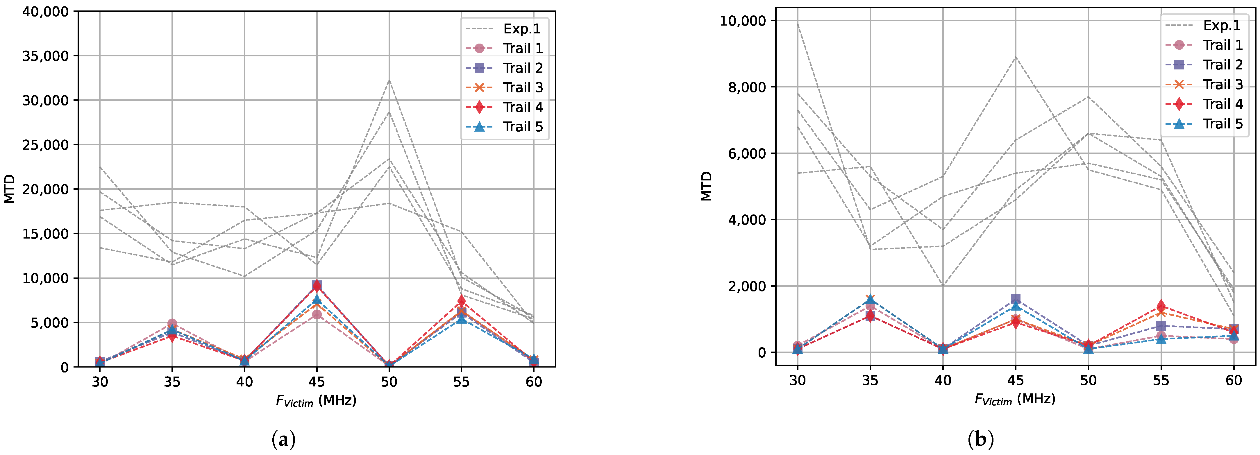
  • MTD: The minimum number of traces needed to recover the key. If the MTD value is smaller, it proves that it is easier to recover the key through the CPA attack.
When all sub-keys are successfully recovered, we employ the MTD to quantify the efficacy of CPA. Conversely, when CPA fails to extract all sub-keys, we utilize GE and PSR to assess the efficacy of CPA. For the SM4 algorithm, there are only 4 sub-keys per round, while AES-128 has 16 sub-keys, so the MTD of the SM4 algorithm is generally smaller than the MTD of the AES-128 algorithm. The maximum GE value of CPA attacks on the SM4 algorithm is 32 while for the AES-128 algorithm is 128.

4.3. Random ϕ and Fixed F A t t a c k e r

Our first set of experiments assumes that the attacker collects power traces at a fixed sampling frequency. The attacker does not know the clock phase of the attacked circuit, so when collecting power traces, there is a random phase difference between the attacker’s sampling clock and the clock of the attacked circuit. This scenario represents the most generalized remote CPA attack targeting the multi-tenant FPGA.
We use the same bitstream to perform CPA attacks on each FPGA platform, the physical structure of the circuit is the same, but different values of F V i c t i m are applied during the operation. We repeat the experiment five times for each F V i c t i m to assess the effect of the initial random phase difference and eliminate the interference of factors such as noise.
Figure 5 and Figure 6 illustrate the trends in MTD versus F V i c t i m on Artix-7 FPGA and UltraScale+ FPGA. On Artix-7 FPGA, because when F V i c t i m = 60 MHz, even if 30,000 power traces are collected, there are always some sub-keys that cannot be extracted successfully, so the MTD value of F V i c t i m = 60 MHz is missing in Figure 5a. There is a large difference in MTD values between different CPA attacks in Figure 5 and Figure 6, because of the random phase difference between the two CMTs at restart. Furthermore, our results indicate that the UltraScale+ FPGA exhibits higher MTD of CPA attacks than the Artix-7 FPGA. The higher MTD values of the UltraScale+ FPGA are attributed to more available hardware resources and the use of fewer percent resources for equivalent circuit implementations, leading to voltage drops that are more difficult to detect.
For the case of random ϕ , we use the theoretical model in Section 3.2 to calculate the EPQ corresponding to each F V i c t i m at a sampling frequency of 300 MHz in the range of 180 to 180 with a step size of ϕ in 30 . Because t p v a l i d in the model only depends on the physical structure of the circuit, we set t p v a l i d to a fixed value of 1.5 ns for Artix-7 FPGA and 1.1 ns for UltraScale+ FPGA (derived from the Vivado implementation report) when modeling.
The EPQ values simulated by the model are shown in Figure 7, where Figure 7a corresponds to EPQ calculated on Zedboard with Artix-7 FPGA and Figure 7b corresponds to EPQ calculated on ZCU102 with UltraScale+ FPGA.
Based on the model simulation results, the EPQ is significantly influenced by F V i c t i m and the initial phase difference ϕ . Our experimental results also confirm this, and there is a large difference between MTDs for different CPA attacks because of the different ϕ and different F V i c t i m .
First, consider the effect of F V i c t i m during the victim circuit operation. When ϕ stays constant, if the victim circuit changes its clock frequency, the EPQ value can increase. This means the ability to resist power analysis attacks becomes weaker, which raises the risk of unexpected side-channel leakage.
Next, consider the initial phase difference ϕ . According to the results calculated by the model, for some frequencies, the EPQ is greatly affected by ϕ , so in our experiments, the MTD value varies greatly between different CPA attacks at the same F V i c t i m .

4.4. Fixed ϕ and Fixed F A t t a c k e r

In our second experimental setup, we assume the attacker acquires power traces at a constant fixed sampling frequency F A t t a c k e r , with an initial phase difference ϕ of 0 between the attacker’s sampling clock and the victim circuit’s clock. Similarly, we repeat the experiment fitve times for each F V i c t i m to eliminate interference from factors such as noise.
When ϕ is fixed to 0, the CPA attack cannot obtain all sub-keys at a certain F V i c t i m , such as 55 MHz.Thus, we use GE and PSR to evaluate the performance of CPA. We compare the modeled EPQ with the GE and PSR of the CPA attack, and the results are shown in Figure 8 and Figure 9. Higher GE means worse CPA attack performance, so there should be a negative correlation between EPQ and GE. To make the relationship between the modeled EPQ and experimental GE easier to see, we use 1 / E P Q in Figure 8a,b and Figure 9a,b. The modeled EPQs are represented by gray dashed lines, while the GEs and PSRs derived from five CPA experiments are illustrated as bar graphs. From Figure 8 and Figure 9, when ϕ is 0, the trend of EPQs from our model with F V i c t i m basically matches the performance trend of the actual CPA attack with F V i c t i m . This shows that the EPQ can correctly represent the relationship between CPA attack performance and F V i c t i m when ϕ = 0 . Because we do not examine the exact relationship between EPQ, GE, and PSR. Thus, the minimum EPQ does not always match the F V i c t i m value that is hardest to attack using CPA.
Nevertheless, when the EPQ is low, as observed at F V i c t i m values of 35 MHz and 55 MHz, key extraction via CPA attacks on both AES and SM4 algorithms proves challenging.

4.5. Fixed ϕ and Proportional F A t t a c k e r

Our third set of experiments assumes that the attacker collects power traces at a sampling frequency five times the clock frequency of the attacked circuit, and the phase difference between the attacker’s sampling clock and the initial clock of the attacked circuit is 0. In this case, for any F V i c t i m , the total number of sample points collected is the same.
In the third set of experiments, the EPQs from the model are consistently 0.2 across all values of F V i c t i m for both Artix-7 FPGA and UltraScale+ FPGA, which are higher than the EPQs obtained by modeling in experiments 1 and 2. Therefore, the expected CPA attack performance should be independent of F V i c t i m , and better than experiments 1 and 2.
Figure 10 and Figure 11 shows how MTD changes with F V i c t i m . To compare with the results of random ϕ and fixed F A t t a c k e r , the MTDs in Section 4.3 are plotted in gray. In the case of F V i c t i m is 60 MHz on Artix-7 FPGA, 16 sub-keys of the AES-128 algorithm cannot be all extracted even with 30,000 traces, we use * in Figure 10a to indicate that the sub-keys are not completely extracted with 30,000 traces. It can be seen that for all F V i c t i m , the MTDs remain at a low level, indicating the CPA performance of fixed ϕ and proportional F A t t a c k e r is much better than that of random ϕ and fixed F A t t a c k e r . Across the three groups of experiments, the third exhibited the lowest MTDs. Furthermore, the MTDs showed negligible variance across varying F V i c t i m values, matching the expectations of the model calculation.
For different F V i c t i m , there are small fluctuations in MTDs, which may be caused by the noise of idle FPGA resources and dynamic power consumption of circuit components not related to encryption. Especially on UltraScale+ FPGA, because of less resource utilization on UltraScale+ FPGA. However, overall, for any F V i c t i m , there is no significant difference between MTDs.

5. Discussion and Future Works

Reference [29] mentioned that clock frequency affects the stability of the side-channel signal of long wire information leakage. However, the specific reasons for the impact have not been explored. We designed three sets of experiments to explore the impact of clock frequency on the power side-channel.
Based on the results of three sets of experiments, we can conclude that the changes of F V i c t i m and ϕ will cause the circuit to leak different amounts of information related to confidential data through power consumption. More specifically, when the SFS or DFS framework is implemented as a countermeasure to mitigate power attacks by a voltage drop, inappropriate clock frequency scaling can amplify power side-channel leakage, thereby increasing the vulnerability to correlation power analysis attacks. To the best of our understanding, no prior research has systematically assessed the unintended power leakage resulting from frequency scaling frameworks. Our research extends the security considerations of applying frequency scaling frameworks on multi-tenant FPGAs. We propose a simple and effective model to simulate the effects of the victim’s running clock frequency and the phase difference between the clocks of the attacker and victim by calculating EPQ. The results of model calculation and experiments show that these two factors significantly impact the performance of power side-channel analysis attacks. Therefore, when implementing frequency scaling frameworks on multi-tenant FPGAs for power attack mitigation, careful clock frequency selection is crucial.
We suggest integrating the dynamic clock frequency and phase adjustment within current frequency scaling frameworks to enhance the resistance of circuits in multi-tenant FPGAs against power analysis attacks. The dynamic clock frequency and phase adjustment introduce random misalignment in power traces, making it resist other types of power analysis attacks such as differential power analysis (DPA) or template attacks. The typical frequency scaling framework in reference [5] utilized the dynamic reconfiguration port (DRP) of the Xilinx CMTs. Because the CMTs can change the clock phase while config clock frequency at run-time, integrating this approach into the frequency scaling framework does not lead to hardware cost. In reference [30], the PLL’s multi-channel phase-shifted clock output is used, and a phase-shifted clock is randomly selected as the input clock using the pseudo-random number generator (PRNG) output. According to their results, the resistance of SCA improved by 2000× while introducing only an extra 20 LUTs, 64 registers, eight global clock buffers (BUFGs), and 2 PLLs. References [31,32] evaluates the cost and effect of utilizing Xilinx CMTs to achieve the random clock execution on multi-tenant FPGAs. Their experimental results verified that by only dynamically changing the clock frequency (without changing the clock phase), it is possible to protect against power analysis attacks such as traditional CPA and CPA with fast Fourier transform (FFT) preprocessing, and each of them introduces very little hardware overhead. The main hardware overhead is to use an additional MMCM to generate a dynamically configurable random clock. However, for circuits that have already applied the frequency scaling framework, no additional MMCM overhead will be generated. References [33,34] have proposed a frequency and phase randomization (FPR) method to mitigate CPA attacks, but they all need to instantiate multiple cores, resulting in large hardware overhead. The FPR method randomizes the clock of each core to create several power consumption peaks within one clock cycle, making it harder to align the power traces. Reference [33] implemented FPR on Xilinx PYNQ-Z2 board. The experiment results showed that with the frequency shift method, the MTD increased by 6.54× at best, and with the phase shift method, the MTD increased by 22.92× at best. Reference [34] implemented FPR on a multicore ASIC platform. The experiment results showed the FPR method doubled the MTD of CPA attacks. Integrating this approach into the frequency scaling framework can strengthen defenses against fault injection and power analysis attacks. Therefore, a way to combine the frequency scaling framework with random clock frequency and phase execution is the focus of one of our follow-up works.
However, our work still presents some limitations. We conducted the experiments at a fixed F v i c t i m , the F v i c t i m was adjusted by the DFS framework and was not considered in our experiment. However, the DFS framework needs to receive feedback on real-time voltage changes, and the rate of F v i c t i m changes is relatively slow. Preprocessing methods, such as sliding window (SW) [35], dynamic time wrapping (DTW) [36], principal component analysis (PCA) [37], and FFT [38] can be applied to overcome the misalignment induced by F v i c t i m changes. In our follow-up work, we will further evaluate the performance of multi-tenant FPGAs against CPA attacks under the DFS framework. Moreover, the t p v a l i d value used in our model was directly obtained from the Vivado implementation report. However, due to the complexity of actual circuit implementations, integrating both simulations and experimental measurements to determine a more precise t p v a l i d value is necessary. Additionally, variations in the operating clock frequency can significantly impact the peak dynamic power of the circuit. We need to create a more accurate model to account for this impact in the future.

6. Conclusions

In this work, we proposed a model to fit the effect of the running clock frequency of the victim circuit and the phase difference between the victim’s clock and the attacker’s sampling clock on power analysis attacks in multi-tenant FPGAs, and we designed three sets of experiments to verify the model. Through theoretical analysis and experimental verification, it is verified that the model can fit the ability of multi-tenant FPGA circuits to resist CPA attacks at different operating clock frequencies. Due to the limitations of multi-tenant FPGAs, the sampling rate of the on-chip power sensor used by malicious attackers is typically limited to several hundred MHz. Consequently, users of multi-tenant FPGAs can use the EPQ model to determine the frequency value with minimal EPQ in the most conservative case ( ϕ = 0 ), ensuring that frequency scaling occurs at a lower EPQ. This study offers novel perspectives on frequency scaling within multi-tenant FPGA environments, which can critically enhance the security of applications deployed on multi-tenant FPGAs.

Author Contributions

Data curation, Q.Z. and H.X.; writing—original draft preparation, Q.Z.; writing—review and editing, T.S.; visualization, Q.Z. and H.X.; supervision, T.S.; funding acquisition, T.S. All authors have read and agreed to the published version of the manuscript.

Funding

This research was funded by the Science and Technology Program of Guangdong Province, grant number 2022B0701180001.

Data Availability Statement

The data presented in this study are available upon request from the corresponding author. The data are not publicly available due to privacy reasons.

Conflicts of Interest

The authors declare no conflicts of interest.

References

  1. Krautter, J.; Gnad, D.R.; Schellenberg, F.; Moradi, A.; Tahoori, M.B. Active fences against voltage-based side channels in multi-tenant FPGAs. In Proceedings of the 2019 IEEE/ACM International Conference on Computer-Aided Design (ICCAD), Westminster, CO, USA, 4–7 November 2019; IEEE: Piscataway, NJ, USA, 2019; pp. 1–8. [Google Scholar]
  2. Zhao, M.; Suh, G.E. FPGA-based remote power side-channel attacks. In Proceedings of the 2018 IEEE Symposium on Security and Privacy (SP), San Francisco, CA, USA, 21–23 May 2018; IEEE: Piscataway, NJ, USA, 2018; pp. 229–244. [Google Scholar]
  3. Schellenberg, F.; Gnad, D.R.; Moradi, A.; Tahoori, M.B. An inside job: Remote power analysis attacks on FPGAs. In Proceedings of the 2018 Design, Automation & Test in Europe Conference & Exhibition (DATE), Dresden, Germany, 19–23 March 2018; IEEE: Piscataway, NJ, USA, 2018; pp. 1111–1116. [Google Scholar]
  4. Schellenberg, F.; Gnad, D.R.; Moradi, A.; Tahoori, M.B. Remote inter-chip power analysis side-channel attacks at board-level. In Proceedings of the 2018 IEEE/ACM International Conference on Computer-Aided Design (ICCAD), San Diego, CA, USA, 5–8 November 2018; IEEE: Piscataway, NJ, USA, 2018; pp. 1–7. [Google Scholar]
  5. Luo, Y.; Xu, X. A quantitative defense framework against power attacks on multi-tenant FPGA. In Proceedings of the 39th International Conference on Computer-Aided Design, Virtual, 2–5 November 2020; pp. 1–9. [Google Scholar]
  6. Alam, M.M.; Tajik, S.; Ganji, F.; Tehranipoor, M.; Forte, D. RAM-Jam: Remote temperature and voltage fault attack on FPGAs using memory collisions. In Proceedings of the 2019 Workshop on Fault Diagnosis and Tolerance in Cryptography (FDTC), Atlanta, GA, USA, 24 August 2019; IEEE: Piscataway, NJ, USA, 2019; pp. 48–55. [Google Scholar]
  7. Gnad, D.R.; Oboril, F.; Tahoori, M.B. Voltage drop-based fault attacks on FPGAs using valid bitstreams. In Proceedings of the 2017 27th International Conference on Field Programmable Logic and Applications (FPL), Ghent, Belgium, 4–8 September 2017; IEEE: Piscataway, NJ, USA, 2017; pp. 1–7. [Google Scholar]
  8. Provelengios, G.; Holcomb, D.; Tessier, R. Power distribution attacks in multitenant FPGAs. IEEE Trans. Very Large Scale Integr. (VLSI) Syst. 2020, 28, 2685–2698. [Google Scholar] [CrossRef]
  9. Zhang, F.; Wang, Z.; Shen, H.; Yang, B.; Wu, Q.; Ren, K. DARPT: Defense against remote physical attack based on TDC in multi-tenant scenario. In Proceedings of the 59th ACM/IEEE Design Automation Conference, San Francisco, CA, USA, 10–14 July 2022; pp. 559–564. [Google Scholar]
  10. Drewes, C.; Sheaves, T.; Weng, O.; Ryan, K.; Hunter, B.; McCarty, C.; Kastner, R.; Richmond, D. Turn on, Tune in, and Listen up: Maximizing Side-Channel Recovery in Cross-Platform Time-to-Digital Converters. ACM Trans. Reconfigurable Technol. Syst. (TRETS) 2024, 17, 49. [Google Scholar] [CrossRef]
  11. Glamočanin, O.; Coulon, L.; Regazzoni, F.; Stojilović, M. Are cloud FPGAs really vulnerable to power analysis attacks? In Proceedings of the 2020 Design, Automation & Test in Europe Conference & Exhibition (DATE), Grenoble, France, 9–13 March 2020; IEEE: Piscataway, NJ, USA, 2020; pp. 1007–1010. [Google Scholar]
  12. Krautter, J.; Gnad, D.R.; Tahoori, M.B. FPGAhammer: Remote voltage fault attacks on shared FPGAs, suitable for DFA on AES. Iacr Trans. Cryptogr. Hardw. Embed. Syst. 2018, 2018, 44–68. [Google Scholar] [CrossRef]
  13. Rakin, A.S.; Luo, Y.; Xu, X.; Fan, D. Deep-Dup: An adversarial weight duplication attack framework to crush deep neural network in Multi-Tenant FPGA. In Proceedings of the 30th USENIX Security Symposium (USENIX Security 21), Vancouver, BC, Canada, 11–13 August 2021; pp. 1919–1936. [Google Scholar]
  14. Das, S.; Whatmough, P.; Bull, D. Modeling and characterization of the system-level Power Delivery Network for a dual-core ARM Cortex-A57 cluster in 28nm CMOS. In Proceedings of the 2015 IEEE/ACM International Symposium on Low Power Electronics and Design (ISLPED), Rome, Italy, 22–24 July 2015; IEEE: Piscataway, NJ, USA, 2015; pp. 146–151. [Google Scholar]
  15. Gravellier, J.; Dutertre, J.M.; Teglia, Y.; Loubet-Moundi, P. High-speed ring oscillator based sensors for remote side-channel attacks on FPGAs. In Proceedings of the 2019 International conference on ReConFigurable computing and FPGAs (ReConFig), Cancun, Mexico, 9–11 December 2019; IEEE: Piscataway, NJ, USA, 2019; pp. 1–8. [Google Scholar]
  16. Tian, S.; Moini, S.; Wolnikowski, A.; Holcomb, D.; Tessier, R.; Szefer, J. Remote power attacks on the versatile tensor accelerator in multi-tenant FPGAs. In Proceedings of the 2021 IEEE 29th Annual International Symposium on Field-Programmable Custom Computing Machines (FCCM), Orlando, FL, USA, 9–12 May 2021; IEEE: Piscataway, NJ, USA, 2021; pp. 242–246. [Google Scholar]
  17. Moini, S.; Deric, A.; Li, X.; Provelengios, G.; Burleson, W.; Tessier, R.; Holcomb, D. Voltage sensor implementations for remote power attacks on FPGAs. ACM Trans. Reconfigurable Technol. Syst. (TRETS) 2022, 16, 1–21. [Google Scholar] [CrossRef]
  18. Brier, E.; Clavier, C.; Olivier, F. Correlation power analysis with a leakage model. In Proceedings of the Cryptographic Hardware and Embedded Systems-CHES 2004: 6th International Workshop, Cambridge, MA, USA, 11–13 August 2004; Proceedings 6. Springer: Berlin/Heidelberg, Germany, 2004; pp. 16–29. [Google Scholar]
  19. Baker, R.J. CMOS: Circuit Design, Layout, and Simulation; John Wiley & Sons: Hoboken, NJ, USA, 2019. [Google Scholar]
  20. Rabaey, J.M.; Chandrakasan, A.; Nikolic, B. Digital Integrated Circuits; Prentice Hall: Englewood Cliffs, NJ, USA, 2002; Volume 2. [Google Scholar]
  21. Ganeshpure, K.; Sanyal, A.; Kundu, S. A pattern generation technique for maximizing switching supply currents considering gate delays. IEEE Trans. Comput. 2011, 61, 986–998. [Google Scholar] [CrossRef]
  22. Shan, W.; Zhang, C.; Li, Q.; Yu, J. A Lightweight Countermeasure of SM4 against Side Channel Analysis. In Proceedings of the 2022 8th Annual International Conference on Network and Information Systems for Computers (ICNISC), Hangzhou, China, 16–18 September 2022; IEEE: Piscataway, NJ, USA, 2022; pp. 492–496. [Google Scholar]
  23. Xilinx, Inc. 7 Series FPGAs Clocking Resources (UG472); Xilinx, Inc.: San Jose, CA, USA, 2018. [Google Scholar]
  24. Xilinx, Inc. Large FPGA Methodology Guide, Including Stacked Silicon Interconnect (SSI) Technology (UG872); Xilinx, Inc.: San Jose, CA, USA, 2012. [Google Scholar]
  25. Das, D.; Danial, J.; Golder, A.; Modak, N.; Maity, S.; Chatterjee, B.; Seo, D.H.; Chang, M.; Varna, A.L.; Krishnamurthy, H.K.; et al. EM and power SCA-resilient AES-256 through> 350× current-domain signature attenuation and local lower metal routing. IEEE J. Solid-State Circuits 2020, 56, 136–150. [Google Scholar] [CrossRef]
  26. Li, Y.; Xu, S.; Luo, Y.; Qin, S.; Zhang, S.; Su, M. A Highly Efficient Profiled Power Analysis Attack Based on Power Leakage Fitting. In Proceedings of the 2021 IEEE 23rd Int Conf on High Performance Computing & Communications; 7th Int Conf on Data Science & Systems; 19th Int Conf on Smart City; 7th Int Conf on Dependability in Sensor, Cloud & Big Data Systems & Application (HPCC/DSS/SmartCity/DependSys), Haikou, China, 20–22 December 2021; IEEE: Piscataway, NJ, USA, 2021; pp. 791–796. [Google Scholar]
  27. Liu, C.; Chakraborty, A.; Chawla, N.; Roggel, N. Frequency throttling side-channel attack. In Proceedings of the 2022 ACM SIGSAC Conference on Computer and Communications Security, Los Angeles, CA, USA, 7–11 November 2022; pp. 1977–1991. [Google Scholar]
  28. Kim, Y. Successful Profiling Attacks with Different Measurement Environments for Each Phase. In Proceedings of the Information Security Applications: 15th International Workshop, WISA 2014, Jeju Island, Korea, 25–27 August 2014; Revised Selected Papers 15. Springer: Berlin/Heidelberg, Germany, 2015; pp. 321–330. [Google Scholar]
  29. Ramesh, C.; Patil, S.B.; Dhanuskodi, S.N.; Provelengios, G.; Pillement, S.; Holcomb, D.; Tessier, R. FPGA side channel attacks without physical access. In Proceedings of the 2018 IEEE 26th Annual International Symposium on Field-Programmable Custom Computing Machines (FCCM), Boulder, CO, USA, 29 April–1 May 2018; IEEE: Piscataway, NJ, USA, 2018; pp. 45–52. [Google Scholar]
  30. Ravi, P.; Bhasin, S.; Breier, J.; Chattopadhyay, A. Ppap and ippap: Pll-based protection against physical attacks. In Proceedings of the 2018 IEEE Computer Society Annual Symposium on VLSI (ISVLSI), Hong Kong, China, 8–11 July 2018; IEEE: Piscataway, NJ, USA, 2018; pp. 620–625. [Google Scholar]
  31. Jayasinghe, D.; Ignjatovic, A.; Parameswaran, S. SCRIP: Secure random clock execution on soft processor systems to mitigate power-based side channel attacks. In Proceedings of the 2019 IEEE/ACM International Conference on Computer-Aided Design (ICCAD), Westminster, CO, USA, 4–7 November 2019; IEEE: Piscataway, NJ, USA, 2019; pp. 1–7. [Google Scholar]
  32. Hettwer, B.; Das, K.; Leger, S.; Gehrer, S.; Güneysu, T. Lightweight side-channel protection using dynamic clock randomization. In Proceedings of the 2020 30th International Conference on Field-Programmable Logic and Applications (FPL), Gothenburg, Sweden, 31 August–4 September 2020; IEEE: Piscataway, NJ, USA, 2020; pp. 200–207. [Google Scholar]
  33. Zhu, Y.; Zhou, P. Protecting Parallel Data Encryption in Multi-Tenant FPGAs by Exploring Simple but Effective Clocking Methodologies. IEEE Trans. Very Large Scale Integr. (VLSI) Syst. 2024, 32, 1919–1929. [Google Scholar] [CrossRef]
  34. Yang, J.; Han, J.; Dai, F.; Wang, W.; Zeng, X. A power analysis attack resistant multicore platform with effective randomization techniques. IEEE Trans. Very Large Scale Integr. (VLSI) Syst. 2020, 28, 1423–1434. [Google Scholar] [CrossRef]
  35. Fledel, D.; Wool, A. Sliding-window correlation attacks against encryption devices with an unstable clock. In Proceedings of the Selected Areas in Cryptography–SAC 2018: 25th International Conference, Calgary, AB, Canada, 15–17 August 2018; Revised Selected Papers 25. Springer: Berlin/Heidelberg, Germany, 2019; pp. 193–215. [Google Scholar]
  36. Van Woudenberg, J.G.; Witteman, M.F.; Bakker, B. Improving differential power analysis by elastic alignment. In Proceedings of the Topics in Cryptology–CT-RSA 2011: The Cryptographers’ Track at the RSA Conference 2011, San Francisco, CA, USA, 14–18 February 2011; Proceedings. Springer: Berlin/Heidelberg, Germany, 2011; pp. 104–119. [Google Scholar]
  37. Batina, L.; Hogenboom, J.; van Woudenberg, J.G. Getting more from PCA: First results of using principal component analysis for extensive power analysis. In Proceedings of the Topics in Cryptology–CT-RSA 2012: The Cryptographers’ Track at the RSA Conference 2012, San Francisco, CA, USA, 27 February–2 March 2012; Proceedings. Springer: Berlin/Heidelberg, Germany, 2012; pp. 383–397. [Google Scholar]
  38. Mateos, E.; Gebotys, C.H. A new correlation frequency analysis of the side channel. In Proceedings of the 5th Workshop on Embedded Systems Security, Scottsdale, AZ, USA, 24 October 2010; pp. 1–8. [Google Scholar]
Figure 1. Overview of the threat model. The attacker and victim tenants share an FPGA resource with a common PDN, but tenants are logically isolated on the fabric.
Cryptography 09 00015 g001
Figure 2. Structure of sensors based on TDC.
Cryptography 09 00015 g002
Figure 3. The supply current of a CMOS switch changes with time after the rising edge of the clock arrives. The time window of a detectable power consumption change on the PDN is called t p v a l i d .
Cryptography 09 00015 g003
Figure 4. Mechanism of the frequency impact on the power side-channel under the influence of ϕ . (a) When the phase difference between the attacker’s sampling clock and the victim circuit clock is ϕ 1 , the sampling points can fall within the range of t p v a l i d . (b) When the phase difference between the attacker’s sampling clock and the victim circuit clock is ϕ 2 , the sampling points do not fall within the range of t p v a l i d . (c) When the phase difference between the attacker’s sampling clock and the victim circuit clock is ϕ 1 , the victim circuit increases the clock frequency, and more sampling points can fall within the range of t p v a l i d .
Cryptography 09 00015 g004
Figure 5. Performance of CPA attacks on Zedboard with Xilinx Artix-7 FPGA. The ϕ parameter is randomized. Lower MTD indicates that the attack is performing better. (a) MTDs of CPA attacks on AES-128 algorithm, (b) MTDs of CPA attacks on SM4 algorithm.
Cryptography 09 00015 g005
Figure 6. Performance of CPA attacks on ZCU102 with Xilinx UltraScale+ FPGA. The ϕ parameter is randomized. (a) MTDs of CPA attacks on AES-128 algorithm, (b) MTDs of CPA attacks on SM4 algorithm.
Cryptography 09 00015 g006
Figure 7. EPQ for each F V i c t i m when the attacker sampled at 300 MHz for the random ϕ . A higher EPQ value means that confidential information in the circuit is easier to extract through CPA attacks. (a) EPQ calculated on Zedboard with Artix-7 FPGA, (b) EPQ calculated on ZCU102 with UltraScale+ FPGA.
Cryptography 09 00015 g007
Figure 8. Performance of CPA attacks on Zedboard with Xilinx Artix-7 FPGA. ϕ = 0 , F A t t a c k e r = 300 MHz. Lower GE and higher PSR indicate that the attack is performing better. The modeled EPQs are represented by gray dashed lines, in (a,b), using 1 / E P Q to make the relationship between the modeled EPQ and experimental GE easier to see. (a) GEs of CPA attacks on AES-128 algorithm, (b) GEs of CPA attacks on SM4 algorithm, (c) PSRs of CPA attacks on AES-128 algorithm, (d) PSRs of CPA attacks on SM4 algorithm.
Cryptography 09 00015 g008
Figure 9. Performance of CPA attacks on ZCU102 with Xilinx UltraScale+ FPGA. ϕ = 0 , F A t t a c k e r = 300 MHz. (a) GEs of CPA attacks on AES-128 algorithm, (b) GEs of CPA attacks on SM4 algorithm, (c) PSRs of CPA attacks on AES-128 algorithm, (d) PSRs of CPA attacks on SM4 algorithm.
Cryptography 09 00015 g009aCryptography 09 00015 g009b
Figure 10. Performance of CPA attacks on ZedBoard with Xilinx Artix-7 FPGA. The ϕ parameter is 0, and F A t t a c k e r is proportional to F V i c t i m . Lower MTD indicates that the attack is performing better. For comparison, the MTDs of random ϕ and fixed F A t t a c k e r = 300 MHz are plotted with gray dashed lines. (a) MTDs of CPA attacks on AES-128 algorithm, (b) MTDs of CPA attacks on SM4 algorithm.
Cryptography 09 00015 g010
Figure 11. Performance of CPA attacks on ZCU102 with Xilinx UltraScale+ FPGA. The ϕ parameter is 0, and F A t t a c k e r is proportional to F V i c t i m . (a) MTDs of CPA attacks on AES-128 algorithm, (b) MTDs of CPA attacks on SM4 algorithm.
Cryptography 09 00015 g011
Table 1. Experiments setup.
Experiment ϕ F Attacker
1random300 MHz
20300 MHz
305 × F v i c t i m
Disclaimer/Publisher’s Note: The statements, opinions and data contained in all publications are solely those of the individual author(s) and contributor(s) and not of MDPI and/or the editor(s). MDPI and/or the editor(s) disclaim responsibility for any injury to people or property resulting from any ideas, methods, instructions or products referred to in the content.

