1. Introduction
Discovered by Jacob Rabinow in 1948, magnetorheological (MR) fluids belong to a class of fluids that exhibit variable yield stress, commonly known as non-Newtonian fluids [
1]. Consisting of micron-sized ferrous (Fe) particles suspended in a carrier fluid, they have the ability to change from a fluid state to a semi-solid or plastic state rapidly upon the application of a magnetic field. The degree of change is related to the magnetic field strength and may occur in a matter of a millisecond(s) [
2,
3]. In their semi-solid state, they exhibit field-dependent viscoplastic behavior that is characterized by field-dependent yield stress. This feature along with the fluid’s fast response time has made MR fluids an attractive technology for many applications [
4].
The fluid is commonly used in one of three modes that are shown in
Figure 1. The valve mode is commonly used in damping devices that use MR fluids, such as vehicle suspensions [
5,
6,
7,
8,
9,
10,
11]. The valve mode uses the fluid flow between fixed parallel plates. The shear mode is most often used in real-time-adjustable devices such as MR brakes and clutches. The squeeze mode is far less common than the other two modes. In a limited number of studies, it has been considered for mitigating vibrations with small amplitudes [
12,
13]. In squeeze mode, it is often assumed that the lateral flow of the fluid has Poiseuille-like behavior, which is common to the shear mode application of the fluid. The MR mounts described in this study use the MR fluid within a conventional low-profile elastomeric (rubber) mount. Such a device can potentially be used for adjustable (and adaptable) vibration isolation of highly sensitive electronics and machinery, sensory systems with precise measurement requirements, and other similar applications. As will be described later, the MR fluid provides stiffness and damping characteristics that are far superior to what can be achieved by a conventional rubber mount.
Conventional hydraulic mounts (also called fluidlastic mounts) with MR fluids have been studied in many past studies, mainly for engine vibration isolation [
14]. The forces transmitted by the engine are reduced due to the mount’s compliance and the damping created by the fluid passage through an inertia track, which in some designs also creates a tuned vibration absorber effect. The fluid used in conventional hydraulic mounts is a medium viscosity oil, not too dissimilar to automobile engine oil. Several studies have extended the design and analysis of conventional hydraulic mounts to mounts that use MR fluids [
15,
16,
17]. Among other researchers, Koo et al. have investigated control policies for tuned vibration absorbers, which could be used to control MR fluid mounts [
18].
Other applications of MR material include magnetorheological elastomers, which are a composite of rubber and embedded magnetic particles. The magnetic particles are suspended in the elastomer and are aligned with an applied magnetic field while the elastomer is cured. This applied field causes the microstructures of the iron particles to form chains during the curing, as described by Boczkowska [
19].
Low-profile rubber mounts with an MR-filled interior cavity have also been studied by Wang et al. [
20]. Their study showed that including the MR fluid within the mount increases output force transmission through the mount by a maximum of 75%, for an oscillatory input [
21]. In another study of similar mounts, York et al. showed such mounts to have tunable damping and dynamic stiffness [
22]. As compared with the study by Wang, York’s design includes an internal steel plate to alter the magnetic circuit to place the poles of the electromagnet directly above and below the fluid chamber for improved magnetic efficiency. This design uses a large magnetic field generator, which may be difficult to package. These designs are included in a U.S. patent issued in 2005 [
23].
What the study by Wang and York, and others similar to them do not make clear is how much of the added stiffness is due to including MR fluid, steel plate(s), or other elements that are far stiffer than the rubber. They also do not make it clear how much of the stiffness contributions are due to the change in the mount’s geometry (the inclusion of a cavity within the mount). Additionally, they do not evaluate the change in damping properties of the mount, as compared with a conventional rubber mount, or the extent of damping variation that can be achieved for the range of electrical current that the mount is designed for, most commonly 0–2 A.
Other related studies suffer from the same shortcomings. For instance, the studies in [
24,
25,
26]. In [
24], Hua et al. provide a review of the magnetorheological devices, as studied in the open literature from 2018 to 2020. Some of the devices that are studied are magnetorheological brakes, clutches, dampers, and mounts. The authors conclude that there have been vast advances in the development of magnetorheological proposed in the recent years, although there remain challenges in studying some of the characteristics of the MR devices in shear-squeeze mode, such as the type of the mounts that are studied in this paper.
Kavlicoglu, B. et al. introduced a magnetorheological mount that can reduce or increase its stiffness based on payload and shock and vibration input [
25]. The paper describes the details of the fabrication and testing of the proposed mount, which is fundamentally different from the low-profile MRFM that is discussed here. Additionally, the study in [
25] does not provide any assessment of the differences between the MR mount and similarly configured elastomeric mounts. Specifically, it does not make it clear how much of the mount’s performance is due to the MR fluid and what aspects of the laboratory results are due to the elastomeric construction of the mount.
Jalali et al. described the design, fabrication, and testing of a bi-directional shear mode magnetorheological mount [
26]. The mount is designed so that the movements in both vertical and transverse directions can be accommodated by the shear mode of the MR fluid. How the MR fluid is used in this design, as well as its intended practical applications, are entirely different from our study. Additionally, similar to other papers, this study does not make clear the differences between the proposed MR mount and a similarly configured fluidlastic mount. It does not evaluate the performance improvements and benefits due the MR fluid. This study aims at providing a more in-depth evaluation of the stiffness and damping characteristics of the rubber mounts with embedded MR fluid, referred to as MR fluid mount (MRFM). The evaluation is intended to shed a light on how MRFM performs in various frequencies that are expected to be encountered in isolating sensitive machinery and equipment. Additionally, an in-depth comparison is performed with conventional rubber mounts of the same geometry to differentiate between the contributions of the rubber component and MR fluid.
After describing the MRFM configuration, the paper provides some of the design analysis that is performed in fabricating a series of prototype mounts for the study. Next, it provides the test setup and an analysis of the test results.
3. MR Fluid Mount (MRFM) Analysis, Design, and Fabrication
A model of the electromagnetic circuit for the test prototype shown in
Figure 2 and
Figure 3 is developed using Finite Element Methods Magnetics (FEMM). FEMM analyzes the axis-symmetric vertical cross-section of a magnetic circuit. The model allows evaluating the contours of the magnetic flux density |
B| as well as the magnetic field intensity |
H|, for the mount’s dimensions, material properties, coil windings, and wire gauge at a given supplied current. The
B-H curves for the four different MR fluid (MRF-122, 132, 140, and 145) that are considered for the study are modeled according to
where
B is the magnetic flux (Tesla or kAmp/m),
H is the magnetic field intensity (Amp/m), Φ is the percentage of ferrous iron in the fluid (unitless), and the constant
μ0 = 4
π10
−7 [
28]. The numbering designation for each fluid indicates the percentage of ferrous iron in the fluid by volume. For instance, MRF-122 has 22% volumetric ferrous iron, and Φ is set to 0.22 for the fluid. Changing the magnetic field intensity
H from 0 to 600 kAmp/m in Equation (1), we can determine the magnetic flux
B and use it in the FEMM model to determine flux density within the electromagnetic circuit, as shown in
Figure 4. The FEMM analysis is mainly used to highlight any bottleneck that may exist in the magnetic circuit and change the geometry to achieve a more uniform flux density or flux flow through the circuit.
For brevity,
Figure 4 is used as a sample for the extensive FEMM analysis that was performed for the study. The complete analysis is available in [
27]. The same document also includes the details of the rubber selection, model design, and fabrication of various mounts that are shown in
Figure 5.
The dimensions for each mount are documented in
Table 2. Additionally, the designation abbreviations used for each mount are included in
Table 3. The mount designations in
Table 3 and
Figure 5 are according to the inserts, or lack thereof, for each mount. Two of the mounts have metal inserts, one 6061 aluminum, and another 1018 steel insert. The other two mounts shown in the figure have no metal inserts. One is built with an air cavity where the metal insert is normally placed and the other one is simply made of rubber with no metal inserts or air cavity. The choice of the mounts is so that the stiffness and damping characteristics of the MRFM can be related to different aspects of the mount. For instance, differentiating between the MRFM with aluminum (non-ferrous) and steel insert allows us to evaluate the contributions due to the changes in MR fluid yield stress, as the former allows the magnetic flux to flow through the fluid and the latter does not. The comparison with the air mount and rubber mount allows determining how much of the mount’s performance is due to the compression properties of the fluid. The rubber mount also allows assessing how much of the stiffness and damping of the MRFM is due to the rubber material itself.
4. MRFM Test Setup
The mounts were tested in a suspension dynamometer, shown in
Figure 6. The crossbar is used to preload the mount to approximately 100 N in order to reflect the static load that would be placed on it in practice. Due to the variations in the stiffness of the mounts that are tested (
Figure 5), the static load causes different static displacements, which is included in the analysis of the test results. The mounts are run through a warm-up period of approximately one minute before data collection. Unfortunately, a temperature reading was not possible due to the lower housing blocking the infrared temperature sensor. Therefore, the warm-up was done by running a sine-sweep test at a current setting of 2.0 A at a defined slow rate for a specific length of time. The warm-up was used in both the quasi-static and dynamic testing formats for the three MRFM filled with MRF-145 (MRE 1–3), one empty metal-elastic mount (MRE 3B), one empty elastic mount (AIR), one solid elastic (RUB), one elastic case mount with steel insert (STE), and one elastic case mount with aluminum insert (ALU). The MRE 3B and AIR are nearly the same, in the sense that for both the fluid cavity is not filled with MR fluid. The MRE 3B, however, has a metal insert (12L14 steel, the same as for all of the MR mounts), whereas AIR does not have a metal insert.
For the quasi-static tests, a ramp input from 0 to 1 mm over 3 s is used for the softcore mounts, and a ramp input from 0 to 0.5 mm over 3 s is used for the solid core mounts in
Figure 7a. The sinusoidal displacement in
Figure 7b is used for the dynamic tests, with the amplitude and frequencies shown in
Table 4. The tables show the electrical current variation for each type of mount, along with the amplitude and frequency that was used for each displacement input. The test conditions were adjusted according to the normal stiffness of the mounts to ensure that the resulting forces remain within the limits of the dynamometer load cell (2000 lb). For instance, the mounts with solid cores, which are denoted with an asterisk, were tested at 0.25 in amplitude since 0.5 in result in forces that are larger than the loadcell’s maximum force rating, 2000 lb or 9000 N.
5. Test Results
To establish the stiffness for each of the mounts in
Table 3, they were tested with the quasi-static ramp displacement in
Figure 7a. The stiffness plot in
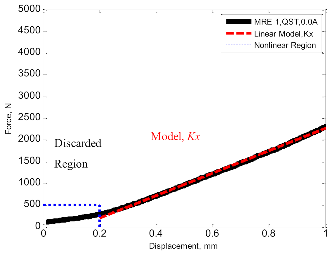
Figure 8 shows a sample of the results for each mount. The initial displacement due to preloading the mount is discarded for the dynamic stiffness analysis because it simply represents the mount’s response to the static load placed on it. The displacements beyond 0.2 mm are used for the dynamic analysis throughout the study. The test result indicates a linear stiffness within the dynamic range, with a slope of K, which can be established through a simple curve fit. The stiffness K of various mounts considered for the study are summarized in
Table 5.
As expected, the two mounts without a metal insert or MR fluid have the smallest normal (vertical) stiffness, whereas the two with the metal inserts have the largest stiffness. The MRE 3B mount has a slightly higher stiffness than the AIR mount, but significantly lower than RUB, mainly because MRE 3B has an air pocket that causes a significant reduction in stiffness. The MRFM offers stiffness that is lower than the two mounts with metal inserts and the one mount with no insert. Unlike the other mounts that have no mechanism to respond to the supplied current, the MRFM’s stiffness increases with increasing current, at a slightly different rate for each of the three mounts. The difference is due to slight variations in manufacturing the prototypes. The percent change in stiffness is 42%, 24%, and 17% for the MRFM, i.e., MRE 1, MRE 2, and MRE 3, respectively. It is also noted that the initial stiffness for each mount is slightly different. The differences are attributed to slight changes in fabricating the prototypes in the lab. They could also be caused by any slight variations in the depth of epoxy primer substrate on the metal poles, which increases the magnetic impedance and reduces flux density within the MR fluid.
The response of the mounts to the sinusoidal dynamic displacements shown in
Figure 7b is also measured to establish their dynamic characteristics. Unlike the quasi-static stiffness tests, the dynamic tests involve analyzing the force-displacement response within one or more cycles, as shown in
Figure 9. The red dashed line is the mount force-displacement plot from the quasi-static tests and its slope represents the mount stiffness. The dynamic tests are performed at 0.0, 0.5, 1.0, 1.5, and 2.0 As for all mounts in
Table 4. The sinusoidal displacement was swept from 1 to 35 Hz at a slow rate, to highlight the changes in mounts’ stiffness and damping with frequency.
Similar to the stiffness tests, the initial displacement from the free height is ignored since it represents the deflection due to the static load on the mounts. The remainder of the cycle is used for the analysis. The test cycle includes the loading (compressing) and unloading (relieving) of the mount during the dynamic cycle. The results clearly show the significant hysteresis that is present in MRFM. The hysteresis is estimated to be caused by both the elastomer and the MR fluid. The equivalent damping coefficient of the mount can be calculated as
where
is the energy dissipated per cycle,
ω is the input frequency in rad/s, and
X is the displacement amplitude [
28]. The energy dissipated per cycle,
is calculated using the
polyarea.m function in Matlab.
Figure 10 shows the dynamic test results for one of the MRFM at 1 Hz, with the supplied current varying from 0.0 to 2.0 A, in 0.5 A increments. The last plot shows the straight-line fit for each current.
The results show that, as expected, the mount stiffness increases with increasing current, as indicated by the slope of the straight line. Interestingly, the plots also indicate that the hysteresis loop grows in width with the increasing current. This means that increasing the supplied current not only increases the MRFM’s stiffness, but also their damping.
The flux density,
B, across the MR fluid is shown in
Figure 11. Since it was not possible to measure the flux density during the tests, the figure shows the FEMM modeling results for various currents. There is a slight amount of warping of the magnetic field toward the edges, which often occurs due to the transition from a magnetic to non-magnetic medium. For the most part, the flux density is constant across the MR fluid. Additionally, the difference in flux density at 2 and 3 A, is far smaller than other currents, indicating that the fluid is approaching its magnetic saturation beyond 2 A. For the tests, the supplied current is capped at 2.0 A.
Many tests are performed on the mounts listed in
Table 4 and the complete results are documented in [
27]. The results are used to determine the change in each mount’s stiffness and damping at various frequencies. They are also used to determine how much of the stiffness and damping that is measured during the tests are due to the MR fluid and how much is because of the elastomer and metal inserts. As noted earlier, to the best of our knowledge, no past study has explored this aspect of MRFM.
As shown in
Figure 12a for one of the MR mounts, there is a significant increase in stiffness with the applied current. More notably, the increase in stiffness is steadily increasing with increasing current, which suggests that the magnetic circuit (including the MR fluid) has not reached saturation. The stiffness increases by 78% at 2 A relative to 0 A supplied current. Concurrently, the equivalent damping for the MR mount in
Figure 12b also increases with the current, but on a larger scale than the stiffness magnitude. The increase in damping force is more than 500% for 2 A, relative to 0 A. The increase in damping, however, mainly occurs at low frequencies and it significantly tapers off with increasing frequencies. At the higher frequencies, there is not a significant increase in damping for various supplied currents. This is an exceedingly interesting and intriguing result, as in practice the mount is desired to have higher damping at lower frequencies to reduce any resonance peaks and have lower damping at higher frequencies to reduce vibration transmission (or improve isolation). The results indicate that the MR mount is able to deliver damping when needed and significantly taper it off when it is not desirable. The results in
Figure 12 are summarized in
Table 6.
Comparing the results in
Figure 12 and
Table 6 with similar results for the rubber mount (RUB) in
Figure 4 provides the stiffness and damping changes due to the MR fluid. As shown in
Figure 13 and
Figure 14, the MR mount with zero current (i.e., with no MR fluid effect) has slightly larger stiffness and nearly the same damping as the rubber mount. The slight increase in stiffness (
Figure 13a) is due to the MR fluid having a larger normal stiffness than rubber when no current is passing through it.
Figure 1a suggests that the MR fluid’s damping is nearly the same as rubber at nearly all frequencies when no current is supplied to the fluid.
When the MR fluid is subjected to 2 A of supplied current, an entirely different picture emerges. For that condition, the MR mount offers far higher stiffness (
Figure 13b) and damping (
Figure 14b). The difference between the mount with no current and max current (2 A) is entirely due to the increase in the MR fluid’s yield strength when it is squeezed as a result of a normal force applied to the mount. At its peak, stiffness has increased by nearly 200% and damping has increased by 700%. At higher frequencies, the gap between MRFM and rubber mount narrows, particularly for damping. As stated earlier, the MRFM’s damping decreases significantly at higher frequencies.
Figure 14b indicates that the MRFM’s damping at higher frequencies is primarily due to the elastomer and not the MR fluid. It can be concluded that the MR fluid in squeeze mode offers little to no damping at higher excitation frequencies but provides plenty of damping at lower excitation frequencies.
As noted earlier, a more comprehensive treatment of the comparison between the MRFM and other mounts in
Table 4 is included in [
27], but not included here for brevity.
6. Conclusions
The study provides a critical evaluation of stiffness and damping characteristics of low-profile magnetorheological (MR) fluid mounts (MRFM) through an extensive series of laboratory tests, some of which are provided in the paper. The reader is encouraged to consult reference [
27] for the complete study. Compared with earlier studies, the analysis offered in this paper provides an in-depth evaluation of the effect of MR fluid on the stiffness and damping of MRFM, which has not been studied in the past.
The design, analysis, fabrication, and testing of a unique class of MRFM that is suitable for the isolation of sensitive machinery and sensors is provided. The prototype MRFM that is fabricated and tested for this study is most suitable for light loads but can be sized up for applications that require supporting heavier equipment, such as automotive engine mounts. The mounts are unique in the sense that the MR fluid is used in the squeeze mode, which has not been studied as widely as the other modes, namely the valve and shear modes. The test results are compared with various mounts to enable directly assessing the contributions of the MR fluid and steel inserts that are needed for efficient magnetic flow through the fluid. For brevity, only the comparison between MRFM and the rubber mount was included in the paper with the intent to mainly highlight the benefits gained from MRFM, as compared with rubber mounts. The test results for a frequency band of 1 to 35 Hz show that the MRFM has slightly higher stiffness and nearly the same damping as a conventional rubber mount when no electrical current is supplied to it (i.e., the MR fluid is “off” or in its free-flowing state). The slight increase in MRFM stiffness is due to the MR fluid having a larger compressive stiffness than rubber. The stiffness and damping of the MRFM increase significantly at lower frequencies when a current is applied to it. The increase in both stiffness and damping is directly proportional to the supplied current. Ranging from 0.0 to 2.0 A, the supplied current contributes to increasing the MR fluid’s yield stress, and its resistance to normal loads in the squeeze mode. Interestingly, this effect significantly tapers off at higher frequencies. For instance, for the 2 A supplied current, the test result indicates that MRFM has 200% higher stiffness and 700% higher damping than the rubber mount, at lower frequencies. However, its damping and stiffness are nearly the same as the rubber mount at higher frequencies (near 35 Hz.). The interesting and intriguing performance of MRFM make them an ideal vibration isolation device, in the sense that they offer high damping and stiffness when needed and taper off when lower damping and stiffness are desired.


