Article

Diffraction of Partially Coherent Light as a Nonlinear Operation

1
Ulyanovsk Branch, Kotelnikov Institute of Radio Engineering and Electronics of the Russian Academy of Sciences, Ulyanovsk 432071, Russia
2
S.P. Kapitsa Research Institute of Technology, Ulyanovsk State University, Ulyanovsk 432970, Russia
*
Author to whom correspondence should be addressed.
Photonics 2026, 13(7), 666; https://doi.org/10.3390/photonics13070666
Submission received: 29 May 2026 / Revised: 6 July 2026 / Accepted: 10 July 2026 / Published: 12 July 2026

Abstract

The linear transformation of optical fields during propagation poses a fundamental limitation for neuromorphic computing applications. In this paper, a realization of a nonlinear operator based on the diffraction of partially coherent light by an aperture partially covered with a binary phase grating is proposed. The dependence of the effective aperture width on the spatial coherence of the incident light produces a nonlinear behavior that formally introduces a nonlinear integration kernel into the propagation integral. The proposed concept is validated through numerical experiments performed using the PyWolf framework for partially coherent light propagation modeling. This coherence-induced nonlinearity, which effectively implements a nonlinear propagation kernel with an input-dependent transfer function, offers a viable pathway to overcome the limitations of purely linear diffractive networks and can be leveraged for constructing multilayer architectures.

1. Introduction

Diffraction of light on a grating is a well-studied optical phenomenon with a long history. Nevertheless, diffraction elements still can serve as a base for completely new photonic devices, photonic neural networks. Photonic neuromorphic systems provide energy-efficient calculations at the speed of light. Diffraction of light easily implements the matrix-vector multiplications that machine learning algorithms are based on. Thus, one of the popular implementations of optical neural networks is the diffraction neural network [1,2]. Diffraction neural networks perform matrix-vector multiplications by propagating light between separate diffractive elements arranged into layers.
One of the key features of neural networks is their multilayered structure. The multi-layered structure allows artificial neural networks to efficiently generalize information. Modern neural networks may contain thousands of layers. However, the laws of light propagation and diffraction are generally linear. Applied to the neural networks, this means that the whole set of linear diffractive layers can be replaced by a single layer. However, single-layered neural networks are not able to single out hierarchical features and learn complex nonlinear dependencies.
To overcome the linearity of the optical diffraction, one may need to utilize electro-optical elements inside the layers of the optical neural network. In particular, several approaches used Kerr nonlinearity [3], electro-optical transformations [4,5], and saturable absorbers [6] to achieve nonlinearity. However, the additional electro-optical transformations would eliminate the advantage of fast processing and energy efficiency in optical neural networks. Recently, several works appeared devoted to the implementation of nonlinearity in otherwise linear optical systems [7,8,9,10]. The approach presented in these works is based on structural nonlinearity: nonlinearity arises from encoding data into the scattering potential.
Here, we introduce a different approach for achieving nonlinear operations for diffractive phenomena. The nonlinearity is introduced through parameter-dependent integration limits in a transformation describing light propagation. Namely, we introduce an aperture whose effective size depends on the coherent properties of the light. The variability of aperture size creates an effective nonlinearity of the laws governing the propagation of partially coherent light (PCL).
Several groups have already utilized PCL in diffraction neural networks [11,12,13,14]. It was found in [11,12,13] that spatial light coherence crucially affects the intensity distribution in optical neural networks. Diffraction neural networks on PCL demonstrated increased resistance to perturbations and better classification accuracy than the networks utilizing coherent light. The importance of light coherence in diffraction neural networks was indicated by Kleiner et al. [14]. Nevertheless, neither of the previous works considered coherence as an information carrier, and nonlocal properties of the coherence were never used for the realization of nonlinear optical transformations that leave an important research gap. What is still missing is a passive optical mechanism in which the statistical properties of the incident field, such as the spatial coherence length, directly control the effective transfer function of the diffractive element. Such a mechanism would allow the optical system to perform an input-dependent transformation without relying on intensity-dependent materials, electro-optical feedback, or active modulation.
In the present work, we address this gap by proposing a binary-phase-grating-based diffractive element whose effective aperture depends on the spatial coherence length of the incident partially coherent field. As a result, the transformation of the cross-spectral density becomes nonlinear: the output coherence properties are determined not only by the fixed geometry of the aperture, but also by the coherence state of the incident light. This provides a physically simple route toward coherence-gated nonlinear optical operations and suggests a possible passive building block for multilayer diffractive photonic architectures.

2. Methods

The propagation of electromagnetic waves is described by linear transformations. For example, the propagation of the scalar component of an electric field E ( r ) from an arbitrary surface Σ to the observation point r can be described by an integral equation [15]
E r ,   ω = Σ G r , r E r , ω d r = L E r , ω ,
where G ( r , r ) is the integration kernel, a transfer function between points r and r , and ω is the frequency of the radiation. The additional dependence of G ( r , r ) on frequency ω is omitted to simplify notations. The integral in Equation (1) represents an integral linear operator L .
Applied to the case of multilayer diffractive networks, Σ could be a surface corresponding to a particular layer of a neural network. Then, when the light propagates through a sequence of two surfaces, Σ followed by Σ , Equation (1) should be applied to E r ,   ω in succession—first for the first plane, then for the second. From a mathematical point of view, this sequential propagation corresponds to the composition of two linear integral transformations L E r , ω and ( L E ) r , ω . The composition of these linear operators yields another linear operator L ~ :
E r ,   ω = Σ G ~ r , r E r , ω d r ( L ~ E ) r , ω
with the kernel
G ~ r , r = Σ G r , r G r , r d r .
Hence, in the case of multiple planes, the sequence of linear transformations L E r , ω can be replaced by a single linear transformation. This fact prevents the construction of truly multilayer optical neural networks.
Electric field strength E ( r ,   ω ) is a commonly used electromagnetic field characteristic. However, electromagnetic field possesses a variety of other characteristics; one of them is spatial coherence. Spatial coherence properties of the field between two arbitrary points r 1 and r 2 at frequency ω are described by the cross-spectral density function (CSD)
W r 1 , r 2 , ω = E * r 1 , ω E ( r 2 , ω ) ,
where the angle brackets denote ensemble averaging and the asterisk stands for complex conjugation. The propagation of CSD from the surface Σ to another surface is described by the following integral transformation [15,16]:
W r 1 , r 2 , ω = Σ G * r 1 , r 1 W r 1 , r 2 , ω G r 2 , r 2 d r 1 d r 2   = M W r , ω ,
where r 1 , r 2 are the radius vectors of two arbitrary points on the surface Σ , and W r 1 , r 2 , ω is the CSD on the surface Σ ; r 1 , r 2 are the radius vectors of two arbitrary points on the observation surface. Despite its more complex appearance, the propagation of a CSD is still described by a linear operator M in Equation (5). By analogy with the derivation of Equations (2) and (3) for the case of two sequentially arranged surfaces Σ and Σ , it can be readily shown that the composition of linear transformations M W r , ω reduces to a single linear transformation. However, later in this article, we demonstrate that certain diffractive elements alter Equation (5) such that the composition rule for the operators M ceases to be a linear operator.
To disrupt the linear composition rule for operator M , we suggest making the integration limits of Equation (5) dependent on the coherent properties of input light on the surface of integration Σ :
W r 1 , r 2 , ω = Σ ( W )   K r 1 , r 2 , r 1 , r 2   W   d r 1 d r 2 ,
where
K r 1 , r 2 , r 1 , r 2 = G * r 1 , r 1 G r 2 , r 2
is the kernel of the integral transform. To simplify the notations, W in Equation (6) stands for W r 1 , r 2 , ω . For the transmission through two successive planes Σ and Σ , Equation (6) generalizes to
W r 1 , r 2 , ω = Σ ( W )   K ~ r 1 , r 2 , r 1 , r 2 ; W   W   d r 1 d r 2 ,
where W W r 1 , r 2 , ω is CSD at the surface Σ , and the integral kernel is
K ~ r 1 , r 2 , r 1 , r 2 ; W = Σ ( W ) K r 1 , r 2 , r 1 , r 2   K r 1 , r 2 , r 1 , r 2 d r 1 d r 2 .
Thus, K ~ r 1 , r 2 , r 1 , r 2 ; W is a function of W ( r 1 , r 2 , ω ) , and Equation (8) becomes a nonlinear integral operator. Nonlinear kernel in Equation (9) prevents the collapse of the sequence of integral transformations Equation (6) into a single linear operation that opens the avenues in the construction of multilayer optical neural networks.
For a concrete implementation of Σ ( W ) dependence, we make the integration limits in Equation (6) dependent on the spatial coherence length (SCL) of incident light. SCL denotes the characteristic scale | r 1 r 2 | over which W r 1 , r 2 , ω is nonzero. The specific definition of SCL will be given later in the text.
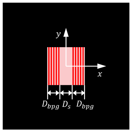
Let us consider PCL incident on a diffractive element, shown in Figure 1. This element comprises a square opening with two identical binary phase gratings (BPGs) positioned at two opposing edges of the aperture. BPGs have a phase modulation of π . In a conceptual thought experiment, each BPG prevents coherent light from propagating in the forward direction due to destructive interference. In contrast, for PCL with an SCL smaller than the grating period, destructive interference is suppressed, allowing the wave to propagate in the forward direction. In other words, the same BPG behaves differently under coherent and partially coherent illumination. Consequently, when placed next to a conventional slit, such a composite diffractive element would have a coherence-dependent effective width. That is exactly the property required to introduce into Equation (8) the dependence of the integration limits on the coherent properties ( W ) of light.
The propagation of a complex electric amplitude E i ( r , ω ) through a thin BPG is governed by the following expression [15,17]:
E t r , ω = t r E i r , ω ,
where E t r , ω is the field behind the diffractive slab, and t r is the complex transmission coefficient. Thus, the CSDs of the transmitted ( W t ) and incident ( W i ) light are related via [15,17]
W t r 1 , r 2 , ω = t * r 1 t r 2 W i r 1 , r 2 , ω .
Note that t r = 0 for the opaque screen, and t r = 1 for the opening not covered with BPG. For BPG, t r = s i g n cos 2 π x / Λ takes the values of 1 and 1 and is spatially modulated with a period Λ which is determined by the period of the grating.

3. Results

3.1. Simulation of PCL Propagation Through a BPG

The experiments on the propagation of CSD were performed using open-source software PyWolf 3.0.0 [18,19]. In PyWolf, the CSD W r 1 , r 2 , ω is discretized in the source plane into an N × N × N × N matrix, where N is the number of discretization points per dimension, resulting in a total of N 4 elements. After creating the source CSD, the field is propagated to the observation plane using a discretized version of Equation (5) in the Fresnel approximation [18].
The current version of PyWolf does not have a built-in ability to model the transmission through diffraction gratings. However, PyWolf allows the use of custom CSD source models, the feature we took advantage of. We employed the following steps to implement the source CSD. At the initial stage, we chose a quasi-homogeneous Gaussian model for the CSD of the incident wave:
W i r 1 , r 2 , ω = S i ω exp r 2 r 1 2 / 2 l c 0 2 ,
where l c 0 is the effective SCL for the quasi-homogeneous Gaussian model, and S i ( ω ) is the spectral density, which is constant for the chosen model of CSD. The four-dimensional matrix W i r 1 , r 2 , ω then was exported from PyWolf to the local drive. Next, we constructed the N × N matrix of transmission coefficients t r for the whole simulated area. Following Equation (10), we calculated the matrix of CSD W t r 1 , r 2 , ω for the wave transmitted through the BPG. The resulting CSD was loaded back into PyWolf and used as a new source CSD. Let us note that no modifications to the PyWolf code were introduced. Thus, the accuracy of the diffraction calculations demonstrated in Ref. [18] remains unchanged.

3.2. BPG Transmission Experiment

In the first experiment, we demonstrate that the transmission of PCL through a BPG depends on the SCL.
The theoretical analysis of the propagation of PCL through diffractive gratings was performed in several previous publications [17,20,21]. However, the analytical expressions obtained in these papers are represented through infinite sums and are hard to interpret. Thus, in the present paper, we limit ourselves to the numerical analysis of PCL propagation through a DPG.
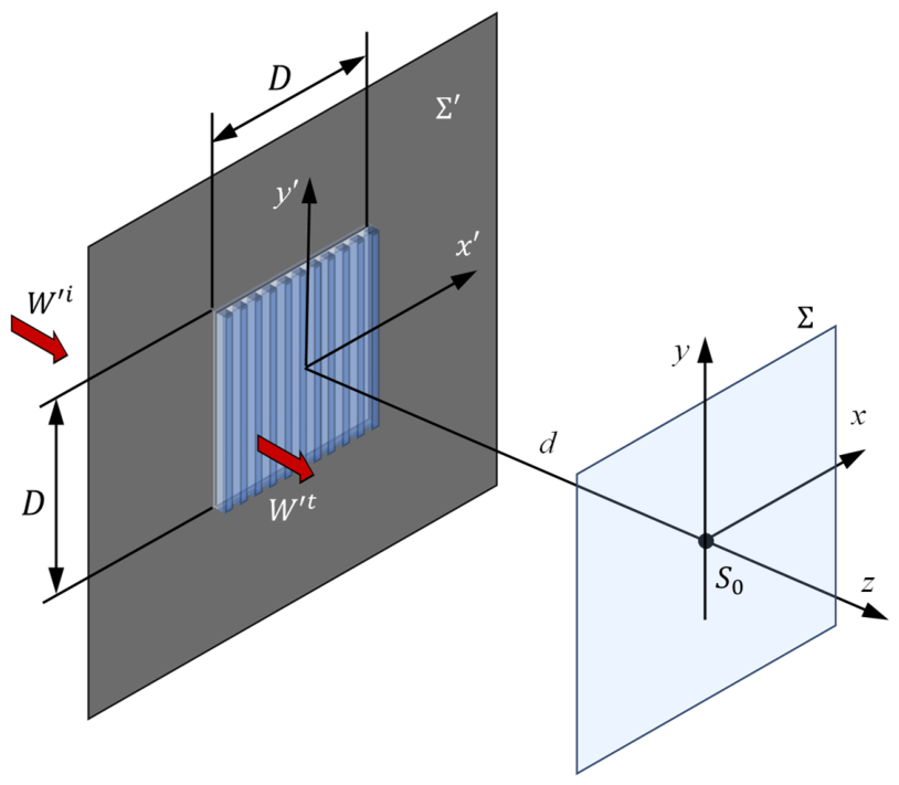
In the numerical experiment, we used a finite-size square BPG positioned at the center of an opaque screen and embedded in air (Figure 2). CSD of incident light W i is transformed by the grating according to Equation (11) to become W t . After the transmission through the grating, PCL propagates over some distance d to the observation point on the z-axis aligned with the center of the grating. We chose the propagation distance d from the source plane Σ to the observation plane Σ large enough to ensure a destructive interference of the rays originating within one period of the BPG. Simple estimations (see Appendix A) yield the following inequality:
d D Λ ω 4 π c ,
where D is the total size of the grating, and c is the speed of light. Let us note that distance d is generally shorter than the Fraunhofer distance d f D 2 ω / c .
The output of the PyWolf simulation was the spectral density (intensity of light) S 0 ω = W 0,0 , ω on the z-axis, measured at the observation point distance d away from the source plane (Figure 2). All the parameters of the simulation are listed in Table 1. CSD matrix dimensions are determined by the computational limitations [18]. The chosen dimensions of simulated area in the source plane and distance d to the observation plane ensure sufficient spatial resolution of 30 μm in the observation plane [18]. The period of BPG Λ is selected to be much larger than the wavelength ( λ = 2 π c / ω 600 nm), justifying scalar diffraction conditions. With the chosen spatial resolution, period Λ also satisfies the Nyquist sampling criterion. The grating contains D / Λ = 15 periods, which is enough to observe interference phenomena. Distance d to the observation point is chosen to satisfy the near-axis phase condition (12).
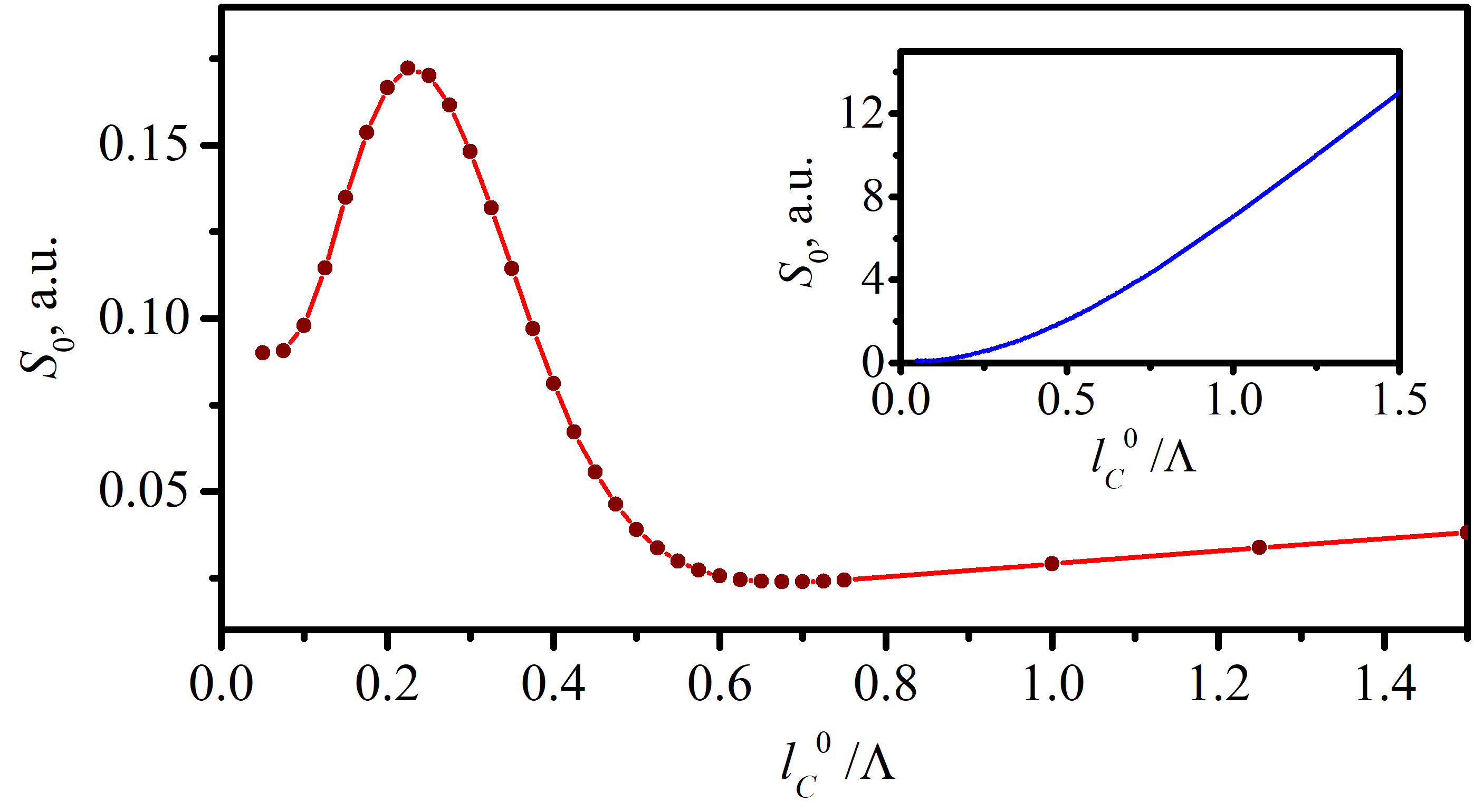
Figure 3 shows the spectral density S 0 calculated for different SCLs of incident light. One can see that the transmission of PCL is low when the coherence length is large relative to the BPG period ( l c 0 > Λ ) . Conversely, PCL with a small SCL ( l c 0 < Λ / 2 ) does not experience destructive interference, and the corresponding spectral density is high. The spectral density drops again for very small SCL ( l c 0 / Λ < 0.2 ) . This drop is caused by the strong divergence of the incoherent light that leads to the spreading of illumination over a large area. Consequently, under this condition, very little light reaches the observation point, even in the absence of BPG (see inset in Figure 3).
The above experiment confirmed that BPG allows transmission of incoherent light into the forward direction, effectively blocking the coherent light. We apply this property in the next numerical experiment for the propagation and transformation of CSD.

3.3. Experiment with a BPG with a Slit

In the next experiment, we examined the diffraction of PCL by a specifically shaped aperture. The aperture consists of a square opening in an opaque screen partially overlaid with two identical BPGs positioned at two opposing edges of the aperture (Figure 1). Two BPGs of width Dbpg are separated by a slit of width Ds. The parameters of numerical simulation are shown in Table 2. In the studied case, both the aperture size and the SCL were more than an order of magnitude larger than the radiation wavelength, corresponding to a state of partial coherence.
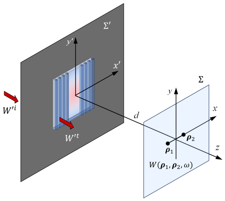
The geometry of the numerical experiment is depicted in Figure 4. After the transmission through the BPG with a slit, PCL propagates over some distance d to the observation plane Σ . The CSD of the propagated light W ρ 1 , ρ 2 , ω is measured at the observation points ρ 1 = x 1 ,   y 1 ,   ρ 2 = x 2 , y 2 in the vicinity of the z-axis aligned with the center of the grating.
The output parameters of the simulation were the CSD W ( ρ 1 , ρ 2 , ω ) and the spectral degree of coherence (SDC) μ ( ρ 1 , ρ 2 , ω ) , measured at the observation plane located a distance d away from the source plane. SDC is defined by the following expression:
μ ρ 1 , ρ 2 , ω = W ( ρ 1 , ρ 2 , ω ) S ( ρ 1 , ω ) S ( ρ 2 , ω ) ,
where ρ 1 , ρ 2 are the radius vectors in the observation plane coplanar to the source plane, and S ρ j , ω = W ρ j , ρ j , ω is the spectral density at the point ρ j . SDC has a property that μ ρ j , ρ j , ω = 1 and | μ ρ j , ρ k , ω | 1 for ρ j ρ k ( j , k = 1 ,   2 ) . After SDC is found, SCL at the observation plane is calculated at the level μ ( l c ) = e 1 / 2 .
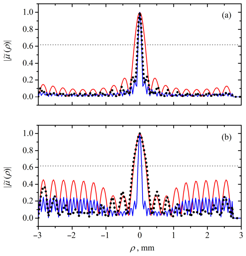
The results of the simulation for the absolute value of SDC measured for two points on the x-axis at coordinates ( 0 ,   0 ) and ( ρ ,   0 ) (denoted as | μ ~ ρ | ) are shown in Figure 5. One can see that, for regular slits (the case of the aperture without BPGs), the measured degree of coherence barely depends on the SCL of the incident light, in accordance with the generalized Van Cittert–Zernike theorem [15]. By contrast, for the BPG-based structure, the observed SDC exhibits a strong dependence on l c 0 .
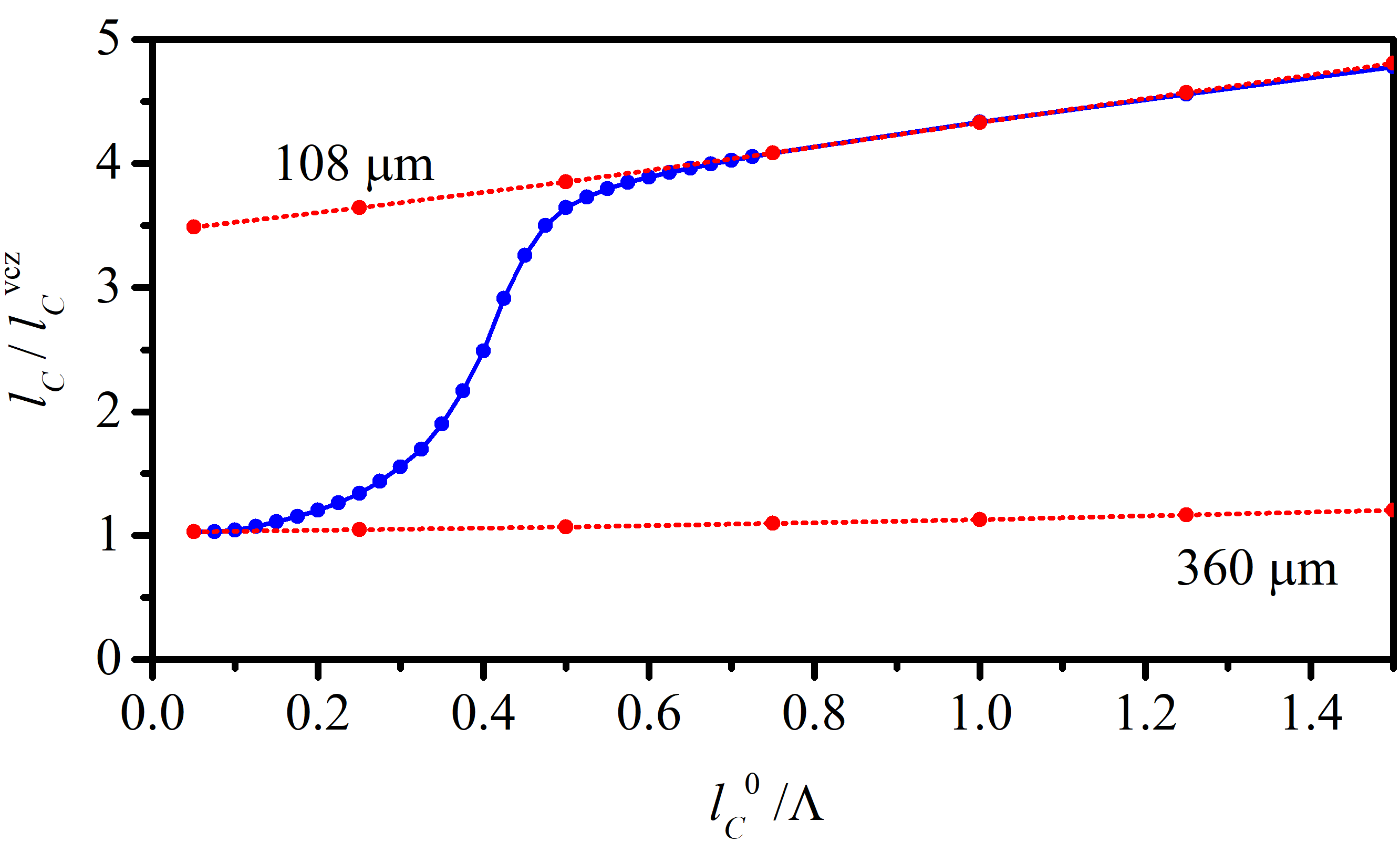
The SCL in the observation plane l c as a function of the SCL of the incident wave l c 0 is shown in Figure 6. For presentation purposes, l c is normalized to the Van Cittert–Zernike coherence length l c v c z for a regular slit of width D , evaluated for the same distance d via the formula [15,16]
l c v c z = 2 π c d ω D .
From Figure 6, one can see that around l c 0 Λ / 3 there is a transition between two propagation regimes. For small SCL ( l c 0 < Λ / 5 ), PCL does not experience destructive interference and propagates through the whole area of the square aperture. Thus, the SCL of the transmitted light is determined by the slit of 360 μm width (bottom red line in Figure 6). For a large SCL of incident light ( l c 0 > Λ / 2 ), the SCL of the transmitted light is determined by the central slit not covered with a diffraction grating. Because of the boundary effects between BPG and the opening, the SCL of the transmitted wave is defined not exactly by the actual geometric slit width of Ds = 120 μm, but by a slightly narrow opening. Empirically, this width is found to be 108 μm (top red line in Figure 6).
One may notice that the top and bottom lines in Figure 6 are not quite horizontal. This fact tells us that the observation plane is not located at a Fraunhofer distance, and the conditions for the Van Cittert–Zernike theorem are not fully fulfilled.

4. Discussion

Figure 6 clearly demonstrates the property of the coherence-dependent variability of diffractive element width. Depending on the relation between the SCL of the incident light and the period of BPG, the PCL propagates either through a central slit or through the whole area of the diffractive element. Consequently, the dependence l c ( l c 0 ) exhibits a pronounced nonlinear behavior for the BPG-based aperture (blue curve in Figure 6), whereas for fixed-width openings it remains quasi-linear (red curves in Figure 6). The effect requires a specific range of SCLs relative to the BPG period ( Λ / 5 < l c 0 < Λ / 2 ). If the coherence length is too large, the grating demonstrates destructive interference; if it is too small, the grating-based structure approaches a conventional aperture.
Let us note that the location, the shape of the transition region, and the amount of the step height of the coherence length l c are not universal constants. They depend on the grating period, slit width, BPG strips width, phase modulation depth, propagation distance, incident CSD model, and the particular definition of spatial coherence length. Despite all possible variations in parameters, the general physical condition persists that the transition occurs when the spatial coherence length of the incident field becomes comparable to the grating period.
Note that the Σ ( W ) dependence manifests itself in the coherent properties of the transmitted light. In particular, for a regular slit, the SCL of the transmitted light in the wave zone does not depend on the SCL of the incident light as a consequence of the Van Cittert–Zernike theorem [15,16]. On the contrary, for the complex diffractive element (BPG-based structure) depicted in Figure 1, the effective width of the aperture would depend on the SCL of the incident light. Thus, the SCL of the transmitted light exhibits dependence on the SCL of the incident field even in the wave zone. In this context, the BPG serves as an interferometric modulator, providing a practical means to realize and control the observed nonlinear behavior.
The nonlinear dependence l c ( l c 0 ) shown in Figure 6 is bounded and exhibits a sharp threshold-like transition, closely reminiscent of a sigmoid activation function widely employed in machine learning [22,23]. The common defining feature of such functions is the ability to mediate a smooth crossover between two distinct states. In this work, however, our goal was not to replicate a specific sigmoidal curve, but to demonstrate that the proposed physical system inherently provides a comparable switching behavior. Importantly, going beyond standard sigmoidal forms, the grating profile can be further tailored via apodization or chirping, offering a route to realize a broader family of activation functions.
Let us note that achieving the functional dependence Σ ( W ) for an electric field E ( r , ω ) would require intensity-dependent optical properties and hence large field intensities. In contrast, the implementation Σ ( W ) for CSD does not require strong fields.
Equation (7) assumes a thin phase mask without diffraction inside the structure. The description of finite thickness requires more complex simulations. Real diffractive structures have finite thickness that may somewhat alter the results. The finite thickness of a diffractive grating may introduce material dispersion, loss, and internal diffraction and interference. These effects may modify the quantitative transfer curve but should not remove the basic coherence-gating mechanism if the required π phase contrast is preserved. Hence, the main conclusion of the paper—the transmission of the diffraction gratings depends on light coherence—remains valid.

5. Conclusions

In this work, we propose a novel approach for implementing nonlinear optical transformations based on the diffraction of PCL. The key idea is to introduce a dependence of the effective integration domain on the cross-spectral density of the optical field, which leads to a nonlinear integral operator governing light propagation.
We demonstrate that a simple diffractive structure consisting of an aperture combined with a phase grating exhibits a transmission behavior that depends on the spatial coherence of the incident radiation. This results in a coherence-dependent effective aperture size and enables the transfer of coherence information into the far field, in contrast to conventional diffraction systems.
Numerical simulations performed using the PyWolf framework confirmed that the SCL of the transmitted field depends on the coherence properties of the input field. This behavior can be interpreted as a nonlinear transformation of the optical signal, suggesting potential applications in diffractive neural networks, where such nonlinearity is essential.
In recent studies [11,14], partially coherent light was introduced into diffractive neural networks. However, coherence in these studies primarily acts as a property of the illumination that modifies the behavior of an otherwise linear diffractive architecture. By contrast, in the present work, the spatial coherence length directly controls the effective aperture width of the diffractive element and therefore changes the optical transfer function itself. Thus, the proposed coherence-gated mechanism is not intended as an alternative training strategy at this stage, but rather as a passive physical nonlinearity that could complement partially coherent diffractive neural networks. A quantitative comparison in terms of classification accuracy or scalability requires the implementation of a complete neural-network architecture based on the proposed element and is left for future work.
The proposed mechanism provides a pathway toward implementing nonlinear operations in purely passive optical systems without requiring high optical intensities or active elements. Future work will focus on analytical modeling of the effect, experimental validation, and the design of optimized diffractive structures capable of realizing specific nonlinear activation functions.
Overall, the results indicate that coherence-controlled diffraction provides a promising route toward implementing nonlinear operations in optical systems without relying on material nonlinearities.


Author Contributions

Conceptualization, S.S.; methodology, S.S., S.M. and I.G.; software, I.G.; formal analysis, I.G.; investigation, S.S., S.M. and I.G.; writing—original draft preparation, S.S. and S.M.; writing—review and editing, S.S., S.M. and I.G. All authors have read and agreed to the published version of the manuscript.

Funding

The work is supported by the Ministry of Science and Higher Education of the Russian Federation in the frame of the government task of the Kotelnikov Institute of Radio Engineering and Electronics of the Russian Academy of Sciences (FFWZ-2025-0005).

Data Availability Statement

The raw data supporting the conclusions of this article will be made available by the authors on request.

Conflicts of Interest

The authors declare no conflicts of interest.

Abbreviations

The following abbreviations are used in this manuscript:
PCLPartially coherent light
CSDCross-spectral density
BPGBinary phase grating
SDCSpectral degree of coherence

Appendix A. Condition for the Observation Point Distance

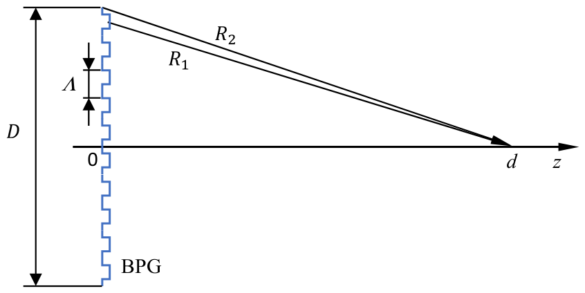
In this Appendix, we derive the condition (12) required for the two rays originating from within one period of the BPG and propagating to the observation point to interfere destructively. For two points, located near the edge of a grating of width D and separated by a half-period Λ /2 of the grating (Figure A1), the path difference Δ R = R 2 R 1 to the point on the optical axis distance d away from the plane of the grating is approximately
Δ R = d 2 + D 2 2 d 2 + D 2 Λ 2 2 D Λ 4 d .
Figure A1. The geometrical layout illustrating the derivation of the condition for the observation point distance.
Photonics 13 00666 g0a1
The corresponding phase difference is
Δ ϕ k Δ R = ω c D Λ 4 d ,
where k = ω / c is the wavenumber. Requiring Δ ϕ π gives approximately
d D Λ 2 λ = D Λ ω 4 π c .

References

  1. Lin, X.; Rivenson, Y.; Yardimci, N.T.; Veli, M.; Luo, Y.; Jarrahi, M.; Ozcan, A. All-optical machine learning using diffractive deep neural networks. Science 2018, 361, 1004–1008. [Google Scholar] [CrossRef] [PubMed]
  2. Wang, Y.; Zhong, M.; Liao, K.; Sun, Q.; Hu, X.; Gong, Q. Diffractive Optical Neural Networks: Pathways Toward Intelligent and Scalable Photonic Computing. Nanophotonics 2026, 15, e70098. [Google Scholar] [CrossRef]
  3. Skinner, S.R.; Steck, J.E.; Behrman, E.C. Optical neural network using Kerr-type nonlinear materials. In Proceedings of the Fourth International Conference on Microelectronics for Neural Networks and Fuzzy Systems, Turin, Italy, 26–28 September 1994; pp. 12–15. [Google Scholar] [CrossRef]
  4. Feng, Q.; Uzundal, C.B.; Guo, R.; Sanborn, C.; Qi, R.; Xie, J.; Zhang, J.; Wu, J.; Wang, F. Femtojoule optical nonlinearity for deep learning with incoherent illumination. Sci. Adv. 2025, 11, eads4224. [Google Scholar] [CrossRef] [PubMed]
  5. He, H.; Cheng, Y.; Zhu, W.; Sun, J.; Sun, J.; Wang, T.; Song, C.; Pan, F.; Zhang, J.; Wang, Y. Reconfigurable Magneto-Optoelectronic Devices for Multidimensional Optical Neural Network. Small Sci. 2025, 6, e202500487. [Google Scholar] [CrossRef] [PubMed]
  6. Dejonckheere, A.; Duport, F.; Smerieri, A.; Fang, L.; Oudar, J.-L.; Haelterman, M.; Massar, S. All-optical reservoir computer based on saturation of absorption. Opt. Express 2014, 22, 10868–10881. [Google Scholar] [CrossRef] [PubMed]
  7. Yildirim, M.; Dinc, N.U.; Oguz, I.; Psaltis, D.; Moser, C. Nonlinear processing with linear optics. Nat. Photonics 2024, 18, 1076–1082. [Google Scholar] [CrossRef] [PubMed]
  8. Xia, F.; Kim, K.; Eliezer, Y.; Han, S.; Shaughnessy, L.; Gigan, S.; Cao, H. Nonlinear optical encoding enabled by recurrent linear scattering. Nat. Photonics 2024, 18, 1067–1075. [Google Scholar] [CrossRef] [PubMed]
  9. Wanjura, C.C.; Marquardt, F. Fully nonlinear neuromorphic computing with linear wave scattering. Nat. Phys. 2024, 20, 1434–1440. [Google Scholar] [CrossRef]
  10. Xia, F. On-chip programmable nonlinearity. Nat. Photonics 2025, 19, 662–663. [Google Scholar] [CrossRef]
  11. Jia, Q.; Shi, B.; Zhang, Y.; Li, H.; Li, X.; Feng, R.; Sun, F.; Cao, Y.; Wang, J.; Qiu, C.-W.; et al. Partially coherent diffractive optical neural network. Optica 2024, 11, 1742–1749. [Google Scholar] [CrossRef]
  12. Qin, J.; Liu, Y.; Liu, Y.; Liu, X.; Li, W.; Ye, F. All-optical Fourier neural network using partially coherent light. Chip 2025, 4, 100140. [Google Scholar] [CrossRef]
  13. Chen, R.; Ma, Y.; Wang, Z.; Sun, S. Incoherent optical neural networks for passive and delay-free inference in natural light. Photonics 2025, 12, 278. [Google Scholar] [CrossRef]
  14. Kleiner, M.; Michalei, L.; Michalei, T. Coherence awareness in diffractive neural networks. Laser Photonics Rev. 2025, 19, 2401299. [Google Scholar] [CrossRef]
  15. Goodman, J.W. Statistical Optics; Wiley: New York, USA, 1985. [Google Scholar]
  16. Mandel, L.; Wolf, E. Optical Coherence and Quantum Optics; Cambridge University Press: Cambridge, UK, 1995. [Google Scholar]
  17. Dušek, M. Diffraction grating illuminated by partially coherent beam. Opt. Commun. 1994, 111, 203–208. [Google Scholar] [CrossRef]
  18. Magalhães, T.E.; Rebordão, J.M. PyWolf: A PyOpenCL implementation for simulating the propagation of partially coherent light. Comput. Phys. Commun. 2022, 276, 108336. [Google Scholar] [CrossRef]
  19. Magalhães, T.E.; Santos, D.O. A new version of PyWolf for the propagation of partially coherent light in media other than free space. Comput. Phys. Commun. 2024, 294, 108899. [Google Scholar] [CrossRef]
  20. Vahimaa, P.; Turunen, J. Bragg diffraction of spatially partially coherent fields. J. Opt. Soc. Am. A 1997, 14, 54–59. [Google Scholar] [CrossRef]
  21. Li, M.; Pang, X.; Schouten, H.F.; Visser, T.D. Far-zone properties of a partially coherent field diffracted by a grating. Opt. Express 2025, 33, 27236–27244. [Google Scholar] [CrossRef] [PubMed]
  22. Shi, W.; Huang, Z.; Fu, T.; Chen, H. Review of nonlinear activation functions in optical neural networks. Adv. Photonics 2025, 7, 064004. [Google Scholar] [CrossRef]
  23. Lederer, J. Activation functions in artificial neural networks: A systematic overview. arXiv 2021, arXiv:2101.09957. [Google Scholar] [CrossRef]
Figure 1. Diffractive element used in calculations: an opaque screen with a square aperture covered by two BPG strips separated by a slit. The opaque screen is shown in black. The color coding of the BPGs and slit indicates the phase of the transmitted light: pink denotes the phase φ = 0 , red denotes the phase φ = π .
Photonics 13 00666 g001
Figure 2. The geometry of the numerical BPG transmission experiment. All the notations in the figure are described in the text.
Photonics 13 00666 g002
Figure 3. Detected spectral density ( S 0 ) at the observation point distance d away from the BPG as a function of normalized SCL of incident light ( l c 0 / Λ ) . The inset shows the detected spectral density as a function of SCL of incident light for the square opening without BPG.
Photonics 13 00666 g003
Figure 4. The geometry of the numerical experiment incorporating the BPG with a slit. All the notations in the figure are described in the text.
Photonics 13 00666 g004
Figure 5. Absolute value of the SDC | μ ~ ρ | for SCL (a) l c 0 =   Λ / 4   = 6   μ m , (b) l c 0 =   3 Λ / 4 = 18   μ m . Different curves show SDC for a 120 μm slit (solid red line), 360 μm slit (solid blue line), and BPG-based structure (black dotted line). The horizontal dashed line shows the level e 1 / 2 , at which the SCL was measured.
Photonics 13 00666 g005
Figure 6. Normalized SCL in the observation plane ( l c / l c v c z ) as a function of normalized SCL ( l c 0 / Λ ) of the wave incident onto the diffractive structure of Figure 1 in the source plane (blue curve). Additionally, SCLs are shown for the PCL transmitted through a 360 μm slit (bottom red line) and 108 μm slit (top red line).
Photonics 13 00666 g006
Table 1. Simulation parameters for the BPG transmission experiment.
ParameterValue
CSD matrix dimensions200 × 200 × 200 × 200
Source spatial resolution6 μm
Dimensions of the simulated area at the source plane1200 μm × 1200 μm
Angular frequency, ω 3.1415 × 10¹⁵ rad/s
Period of BPG, Λ24 μm
Dimensions of BPG, D360 μm
Distance to the observation point, d0.06 m
Table 2. Simulation parameters for the experiment with two BPGs separated by a slit.
ParameterValue
CSD matrix dimensions200 × 200 × 200 × 200
Source spatial resolution6 μm
Dimensions of the simulated area at the source plane1200 μm × 1200 μm
Angular frequency, ω 3.1415 × 10¹⁵ rad/s
Period of BPG, Λ24 μm
Width of the slit, Ds 120 μm
Width of the BPGs, Dbpg120 μm
Distance to the observation point, d0.06 m
Disclaimer/Publisher’s Note: The statements, opinions and data contained in all publications are solely those of the individual author(s) and contributor(s) and not of MDPI and/or the editor(s). MDPI and/or the editor(s) disclaim responsibility for any injury to people or property resulting from any ideas, methods, instructions or products referred to in the content.