1. Introduction
In the realm of vortex beams, photons carry two types of angular momentum: spin angular momentum (SAM) and orbital angular momentum (OAM). The SAM represents the polarization state of light, whereas OAM signifies the spiral phase distribution [
1]. With the helical phase of vortex beams characterized as exp(ilϕ), each photon carries an OAM of lℏ. This imparts a doughnut-shaped intensity profile owing to the phase uncertainty at the vortex beam’s center. The ability of vortex beams has sparked significant research interest, finding extensive applications in optical communication [
2], optical tweezers [
3], super-resolution imaging [
4], and quantum information coding [
5]. The generation of vortex beams is often accomplished through spiral phase plates [
6], holography [
7], and metasurfaces [
8]. When a paraxial beam undergoes tight focusing, a longitudinal electric field component forms within the focal region [
9,
10]. A radially polarized field focused by a high numerical aperture (NA) lens yields a longitudinal electric field in the focal area, whilst azimuthal polarization induces a powerful magnetic field on the optical axis [
11,
12]. Other intriguing optical phenomena, like longitudinal polarization optical needles [
13] and longitudinal vortex knots and links [
14], have also been reported. These longitudinal electric fields offer promising applications in particle acceleration [
15,
16] and harmonic generation [
17], among others. Recent advances utilizing integrated microring resonators featuring gratings have been employed to generate vortex light [
18,
19]. Despite significant progress in understanding transverse electric field radiation, the longitudinal counterpart remains underexplored, constrained by excitation control challenges and measurement constraints.
In this work, we propose a compact integrated THz resonator incorporating a grating structure to generate longitudinal electric field vortices through quasi-TM mode excitation. The method redirects whispering gallery modes (WGMs), which are typically confined within the ring resonator, out into free space via azimuthally periodic refractive index modulation. This mechanism produces electric field vortex beams with helical phase fronts, providing fresh insights into photonic interactions and physical processes. Unlike the previous design schemes mainly based on transverse electric field vortex light, our design enables a longitudinally polarized vortex electric field through the excitation of TM waveguide modes and topological charge control at varying operational frequencies. By using a terahertz near-field scanning system with subwavelength resolution probes, this method quantitatively maps both the spatial intensity distribution and phase profile of the radiation. This platform demonstrates promising applicability in microscale particle manipulation techniques and advanced imaging technologies.
2. Principles and Methods
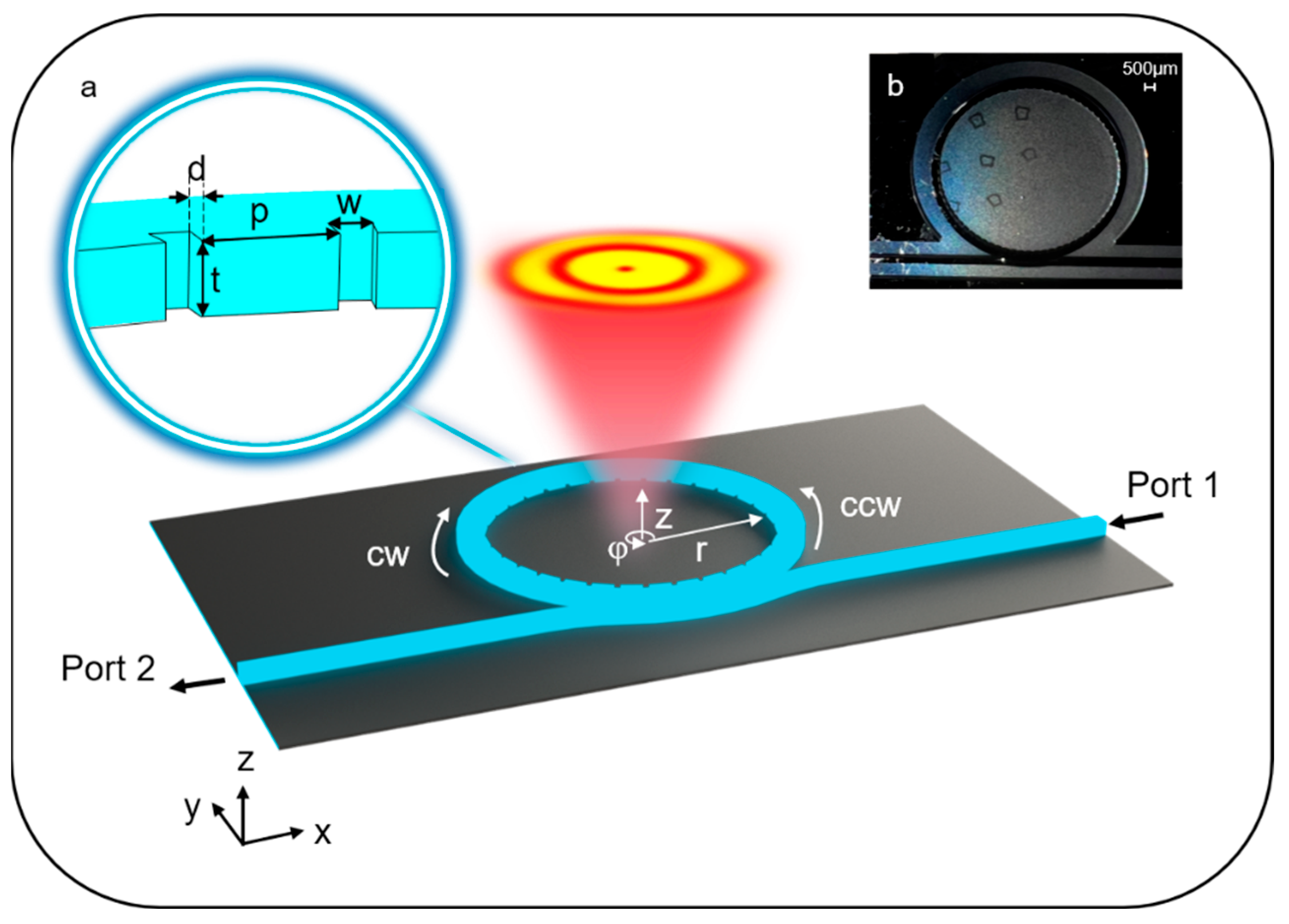
Figure 1a provides an illustrative representation of the designed longitudinal electric field vortex beam emitter on a silicon platform. The ring resonator is formed by a ridge-type silicon waveguide that is 450 μm wide and 400 μm high and placed over a 130 μm slab. The radius of the resonator is 6.9 mm, while 72 grating elements are positioned along the inner sides of the ring waveguide. The grating period is approximately 582.44 μm. The duty cycle is 0.45. There is a 100 μm gap separating the bus waveguide from the ring resonator. The ridge waveguide structure features uniform cross-sectional dimensions of 400 μm (height) × 400 μm (width). The fabricated device’s optical microscope images are presented in
Figure 1b. The device was fabricated on a 4-inch double-side polished intrinsic silicon wafer (resistivity: 20 kΩ·cm) through a lithographic process. First, a 1.3 µm thick SiO
2 layer was deposited on the silicon wafer via plasma-enhanced chemical vapor deposition (PECVD). Subsequently, the grating and ring resonator patterns were defined on the SiO
2 hard mask using reactive ion etching (RIE). The silicon substrate was then structured through inductively coupled plasma (ICP) etching. Finally, the processed wafer was diced into discrete devices for characterization.
In this configuration, a TM mode wave—where the dominant electric field component is oriented along the z-direction—is evanescently coupled from the bus waveguide into the ring resonator, stimulating WGMs. Angular gratings, functioning similarly to second-order gratings in straight waveguide input/output couplers, scatter the guided wave through their periodic elements. A portion of the scattered energy undergoes phase-matched interference along a specific azimuthal direction φ, generating a tilted planar wavefront at angle φ. Critically, when such a grating-integrated waveguide is bent into a ring configuration to support WGMs, Huygens’ principle dictates that the radiated wavefront transitions from planar tilting to helical propagation, which is indicative of OAM-carrying beams. This transformation is physically implemented through azimuthally periodic subwavelength grating elements etched along the resonator circumference, which impose a controlled phase modulation. WGMs represent angular momentum eigenstates with discrete azimuthal propagation constants ν
WGM = β
pR = p, arising from the self-consistent phase requirement for resonance under the periodic boundary condition. The integer p denotes the azimuthal mode number, where R is the effective radius of the WGM, and β
p is the propagation constants at R. The coupling between guided WGMs and radiation modes can be described by the coupled mode theory (CMT), where periodic dielectric constant variations act as perturbations coupling the unperturbed eigenmodes. Equation (1) presents the angular phase matching condition with g representing the diffraction order [
18]:
where q denotes the number of grating periods within the resonator circumference. The implementation of a second-order grating on the WGM resonator enables the second-order diffraction to reflect light into counter-propagating waveguide modes, while the first-order diffraction (g = 1) facilitates outcoupling at a 90° angle, generating a surface-normal propagating field. Hence, when light is injected from the right input port (Port 1), it excites clockwise (CW) propagating WGMs. The topological charge (l
TC) of the emitted OAM beam in the
Ez component can be derived from Equation (2) [
18]:
Due to the z-polarized nature of the quasi-TM mode in the bus waveguide, the radiated vortex beam exhibits a dominant energy concentration in the longitudinal electric field component Ez, which is selectively detected using a THz near-field probe optimized for longitudinal polarization sensitivity.
3. Results
To characterize the device’s performance, we performed numerical simulations of its radiation electric field distribution using a commercial finite-difference time-domain (FDTD) solver (Lumerical Solutions, Inc.). The simulation setup is configured as follows: perfectly matched layer (PML) boundary conditions are applied; the mesh is dynamically generated using an auto-non-uniform algorithm; the absolute global minimum mesh step size (a lower bound for localized refinement) is set to 0.00025 μm; and a TM-polarized waveguide source is used for excitation.
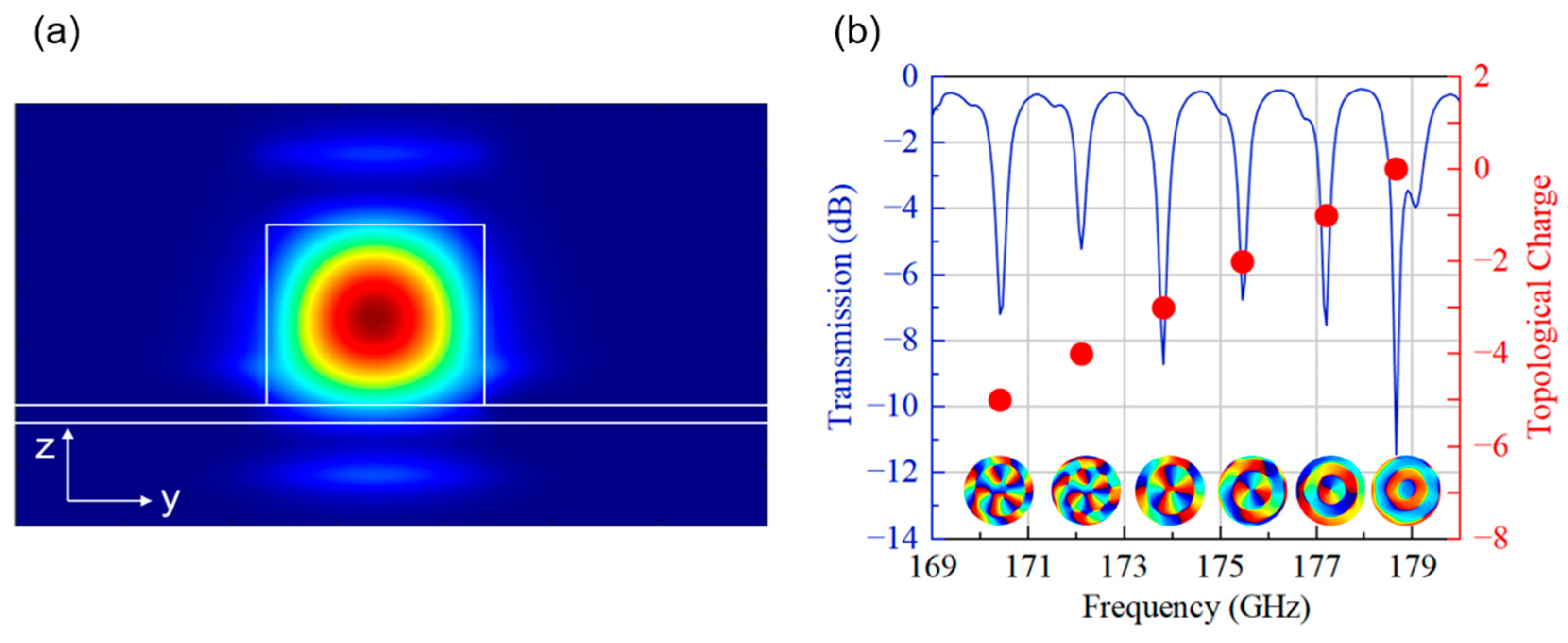
Figure 2a shows the z-polarization simulated electric field distribution of the quasi-TM mode in the bus waveguide.
Figure 2b presents the simulated quasi-TM mode transmission spectrum, showing pronounced WGM resonances indexed by their topological charge l
TC. The transmission spectrum represents the ratio of the output power at port 2 to the input power at port 1 in the bus waveguide. The topological charge l
TC of emitted OAM beams follows Equation (1), establishing a frequency-dependent OAM control as illustrated by spectral markers in
Figure 2b: at resonance frequencies of 173.8 GHz (l
TC = −3), 175.45 GHz (l
TC = −2), 177.2 GHz (l
TC = −1), and 178.65 GHz (l
TC = 0). Notably, the extinction ratio (ER) of different topological charges exhibits some fluctuations, which may stem from computational precision limitations and the inherent frequency dependence of the grating radiation efficiency and bus–ring coupling coefficient. The free spectral range (FSR) is 1.65 GHz. Calculated quality factors (Q) exhibit mode-specific variations, revealing distinct modal loss profiles: 579.33 (l
TC = −3), 701.80 (l
TC = −2), 738.33 (l
TC = −1), and 425.36 (l
TC = 0).
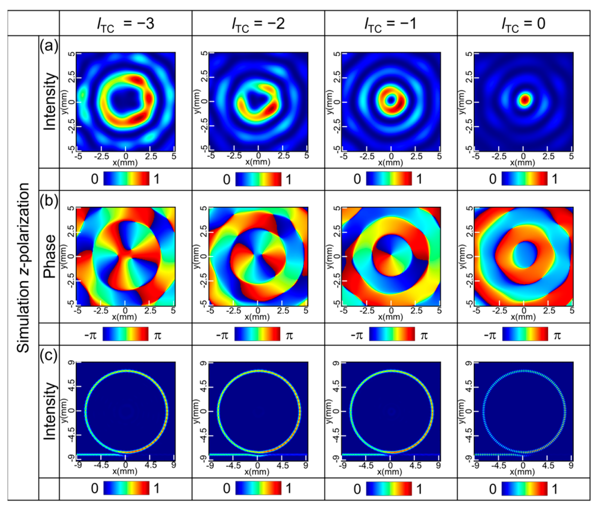
Figure 3 illustrates the simulated intensity and phase distributions (
Ez) of the radiated vortex beam, alongside the mode field distribution across the cross-section of the grating-integrated ring resonator, corresponding to topological charges l
TC = −3, −2, −1, and 0. Their electric field intensities (
Ez) are normalized according to their respective maximum values. Furthermore, the mode field distribution within the grating structure demonstrates that each topological charge (l
TC) corresponds to a distinct resonant excitation frequency of the WGM. The characteristic doughnut-shaped intensity profiles and helical phase discontinuities validate the formation of longitudinally polarized optical vortices. The l
TC = 0 configuration displays a Gaussian-like intensity pattern with negligible OAM, acting as a null-reference for vortex verification.
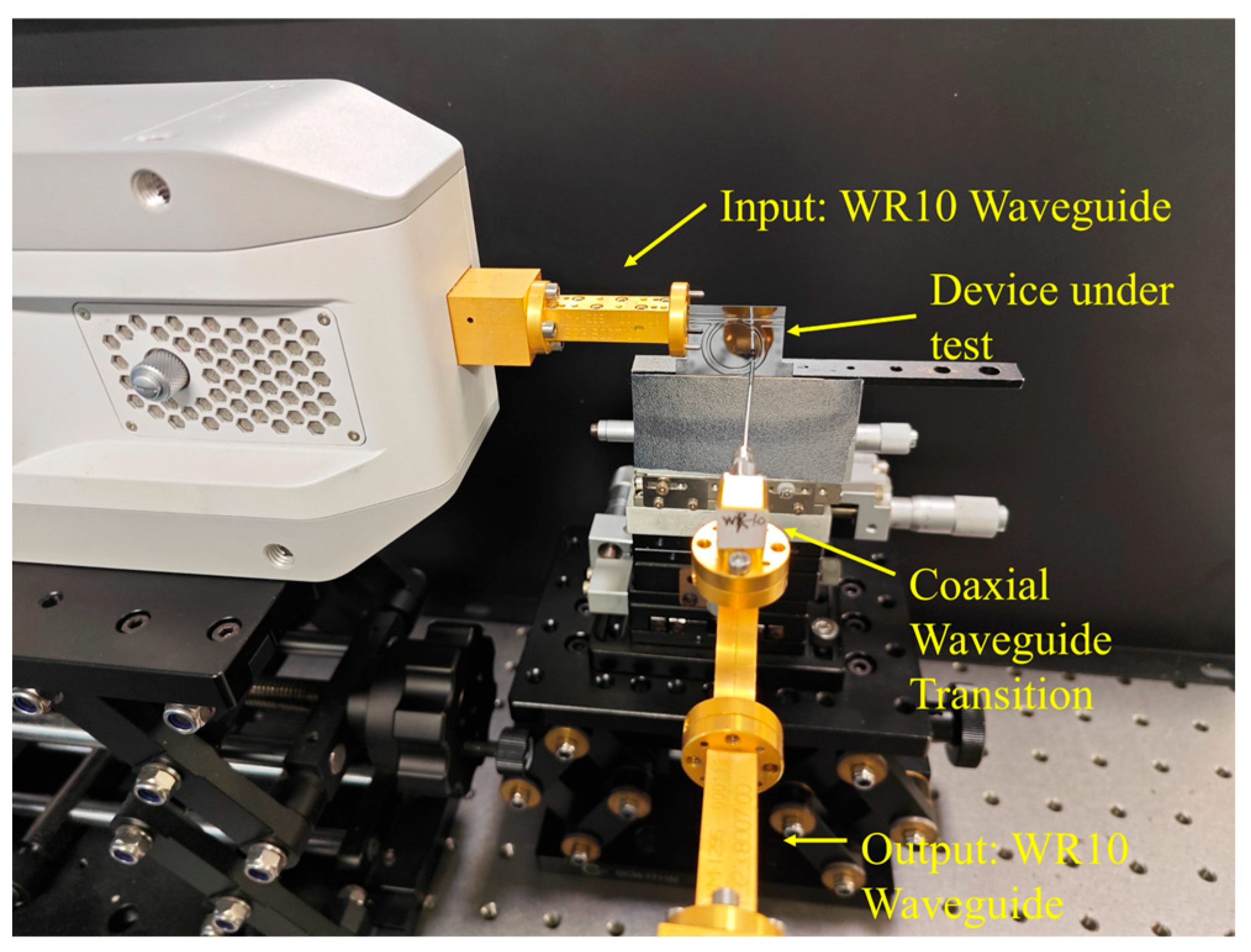
The near-field experimental test system consists of the R&S ZNA26 vector network analyzer (VNA), a two-dimensional motor platform, two WR-5.1 waveguides, and two WR-5.1 140–220 GHz VNA frequency extenders, as shown in
Figure 4. A WR-5.1 metallic waveguide is connected to the frequency extenders. The metallic waveguide couples vertically polarized waves into the bus waveguide via position alignment, exciting its quasi-TM mode. Energy from the WR-5.1 waveguide propagates through the bus waveguide and evanescently couples to the ring resonator. Then, it is radiated via the integrated grating, enabling OAM beam excitation. The receiver is composed of a WR-5.1 metal waveguide and a waveguide coaxial conversion probe. The probe is located at approximately one wavelength from the chip and is perpendicular to the device. The near-field probe can be used to detect z-polarized THz waves. The movement of the probe is controlled by a two-dimensional motor to achieve planar scanning of 5 × 5 mm
2 to obtain the THz intensity and phase distribution.
The transmission spectrum of the device was measured for the TM polarization using the method detailed in our prior work [
20,
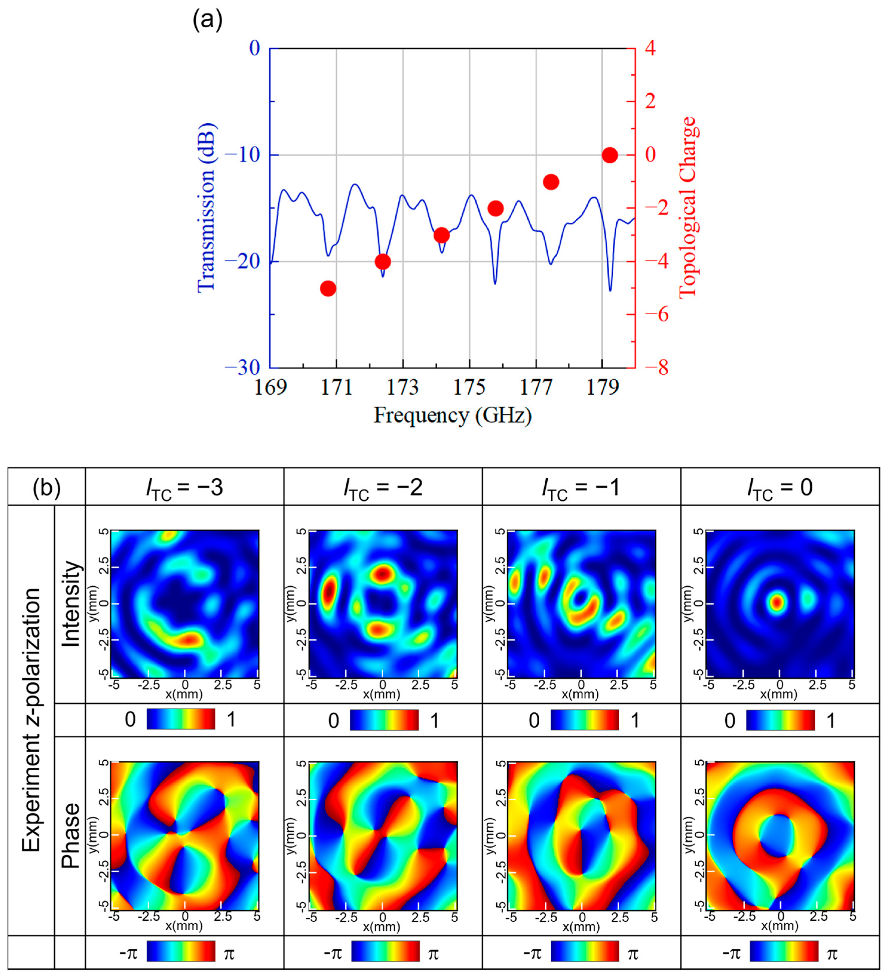
21]. In a rectangular metallic waveguide, the electric field polarization aligns parallel to the shorter sidewall. We selectively excite quasi-TE or quasi-TM modes by orthogonally orienting the frequency extender’s feed structure relative to the waveguide cross-section. Two such waveguides are positioned at opposite ends of the device’s straight waveguide section, serving as THz wave input and output ports. A high-precision displacement stage actively optimizes the waveguide–device alignment, ensuring maximum coupling efficiency through real-time transmission power monitoring. The measured transmission spectrum is shown in
Figure 5a. By comparing the experimental transmission spectrum with the simulation results, it can be observed that the FSR of the experiment is 0.038 GHz bigger than the simulation result, which is 1.688 GHz. The experimental result of the resonant frequency corresponding to the zero-order topological charge has shifted by 0.56 GHz in the high-frequency direction compared with the simulation result. To generate the transmission spectral response, the frequency was swept from 170 GHz to 180 GHz in 0.01 GHz increments. At resonance frequencies of 174.17, 175.77, 177.44, and 179.22 GHz, the device exhibits l
TC values of −3, −2, −1, and 0, respectively. The near-field distribution was characterized via scanning using a subwavelength-resolution probe, displaced across the transverse plane (x-y), enabling the acquisition of the amplitude and phase profiles presented in
Figure 5b. The scanning plane encompassed an area of 5 × 5 mm
2, effectively covering the primary radiation region of the device. Notably, the measured x-o-y plane displayed distinctive doughnut-shaped intensity distributions, while the phase distributions exhibited OAM patterns. Although slight variations in intensity and inhomogeneity were observed, the qualitative agreement between the measured intensity and phase distributions and the simulation results indicated the successful generation of vortex beams.
4. Discussion
The observed radiation intensity nonuniformity of the simulations and experiments (
Figure 3 and
Figure 5) stem from the uniform grating structure. The designed grating exhibits a strong and consistent radiation efficiency across its entire azimuthal span. However, this leads to significant energy emissions from the input region as light initially enters the resonator. Consequently, the energy available for the subsequent propagation diminishes progressively, resulting in the gradual attenuation of the radiation intensity along the resonator’s circumference. Experimental results further amplify this nonuniformity due to fabrication errors and material inhomogeneity. To address this, future designs could incorporate azimuthally chirped gratings to spatially modulate the radiation efficiency. By intentionally reducing the grating coupling strength near the input region and gradually increasing it along the propagation path, such gratings can mitigate early-stage energy radiation and enhance uniformity. The degraded circular symmetry in experimental results (
Figure 5) arises from two factors: (1) stray electromagnetic waves caused by waveguide coupling leakage which interfere with the target signal and (2) the finite spatial resolution of the near-field probe, which distorts azimuthal phase profiles at high topological charges. Despite these discrepancies, key qualitative features are consistent across simulations and experiments. Both confirm helical phase structures for OAM charges (l
TC = −3, −2, −1, 0) and intensity minima at the vortex core (
Figure 3 vs.
Figure 5), validating the phase singularity mechanism.
Furthermore, a comparison between the experimental transmission spectrum and simulation results reveals a 0.038 GHz increase in the FSR (1.688 GHz measured vs. 1.650 GHz simulated). This discrepancy primarily arises from fabrication-induced deviations in the group index and ring circumference of the grating-integrated resonator, caused by the material refractive index and structural variations. Additionally, refractive index variations induce resonant frequency shifts. For instance, the resonant position corresponding to the zero-order topological charge exhibits a 0.56 GHz frequency shift between the experiment and simulation.
In addition, we used a contour integral to calculate the mode purity of different topological charges under analytical, simulated, and experimental conditions. The results are summarized in
Figure 6a–d. Although the primary modes remain consistent across analytical, simulated, and experimental cases, the simulated mode purity slightly decreases compared to analytical predictions. Experimental results exhibit further purity degradation (e.g., 67.4% reduction at l
TC = −3) caused by stray light interference and measurement uncertainties. Future improvements in the device design (e.g., optimized grating coupling coefficients) and advanced characterization techniques are expected to enhance the purity performance.

