Abstract
Free Space Optics (FSO)-based UAV-enabled wireless power transfer (WPT) relay systems have emerged as a key technology for 6G networks, efficiently providing continuous power to Internet of Things (IoT) devices even in remote areas such as disaster recovery zones, maritime regions, and military networks, while addressing the limited battery capacity of UAVs through the FSO fronthaul link. However, the harvested power at the ground devices depends on the displacement and diameter of the FSO beam spot reaching the UAV, as well as the UAV trajectory, which affects both the FSO link and the radio-frequency (RF) link simultaneously. In this paper, we propose a joint design of the divergence angle in the FSO link and the UAV trajectory, in order to maximize the power transfer efficiency. Driven by the analysis of the optimal condition for the divergence angle, we develop a hybrid BS-PSO-based method to jointly optimize them while improving optimization performance. Numerical results demonstrate that the proposed method substantially increases power transfer efficiency and improves the optimization capability.
Keywords:
6G; FSO; UAV; relay system; wireless power transfer; divergence angle; trajectory; optimization 1. Introduction
In the 6G era, radio-frequency (RF)-based wireless power transfer (WPT) plays a vital role in enabling self-sustaining Internet of Things (IoT) networks [1,2,3]. It continuously supplies power to energy-demanding devices such as wearable electronic devices, eliminating the need for frequent battery replacements or dedicated wired power connections. Recently, as unmanned aerial vehicles (UAVs) have gained significant attention in various applications due to their flexibility in deployment, high mobility, and cost efficiency, UAV-enabled WPT has been considered a highly promising solution for efficiently delivering power to IoT devices [1,2,3]. By moving flexibly in three-dimensional (3-D) space and utilizing favorable line-of-sight (LoS) channels, UAV-enabled WPT can reduce transmission distances, avoid obstacles, and reach remote locations where conventional fixed-location power transmitters are ineffective, especially in environments such as disaster recovery, and maritime and military networks that require urgent power supply.
To reap the potential benefits in UAV-enabled WPT systems, a sophisticated UAV trajectory design is required to maximize power transfer efficiency. More specifically, the optimization of one-dimensional (1-D) and two-dimensional (2-D) trajectory design at a fixed altitude was studied to maximize the power transfer efficiency, and further extended to three-dimensional (3-D) trajectory design [4,5,6,7]. As well, a directional antenna array was studied to enhance power transfer efficiency by jointly designing the UAV trajectory and the orientation of the antenna array [8,9]. Energy beamforming, which focuses beams toward devices in the desired directions, was proposed in conjunction with the joint design of the UAV altitude to maximize power transfer efficiency [10]. Furthermore, UAV-enabled integrated sensing and WPT systems were proposed, and the joint design of the transmit waveform and UAV altitude was investigated to simultaneously improve radar sensing performance and power transfer efficiency [11]. To expand WPT coverage, a multi-UAV cooperative WPT system was studied, and an effective multi-UAV trajectory design was explored to improve power transfer performance across various environments [2,3,12,13].
On the other hand, free space optics (FSO) has been considered a key technology for 6G, as it provides high capacity by utilizing the unlicensed spectrum while strengthening security, as well as having low power consumption, reducing operational costs, and avoiding interference with the RF link [14,15,16,17,18]. The FSO system was extensively studied from a communication theory perspective, encompassing channel models, transmitter/receiver structures, modulation, channel coding, and spatial/cooperative diversity techniques [18]. A comprehensive survey of acquisition, tracking, and pointing (ATP) mechanisms for FSO systems was investigated, categorizing the mechanisms based on their working principles, use cases, and implementation technologies [14]. Also, a classification framework for FSO links according to environment, coverage, LOS availability, mobility, and distance was proposed by addressing performance variations across scenarios [15]. A comprehensive tutorial on FSO links in space was presented, covering ground-to-satellite, satellite-to-ground, and inter-satellite links [19], and was further extended to 6G non-terrestrial networks (NTNs), including airborne backhaul system architectures and their use cases [16]. Moreover, UAV-assisted FSO relay systems were extensively studied for practical demonstrations, focusing on commercially available free-flying platforms, categorized by operational altitude and payload capacity, with an analysis of design considerations [17]. More specifically, FSO-based UAV systems that exploit the FSO link as fronthaul/backhaul link were extensively studied to enhance wireless network performance by leveraging the advantages of UAVs, which enable the establishment of strong line-of-sight (LoS) links, while handling the main challenges faced by FSO such as signal attenuation and fading due to atmospheric turbulence [20,21,22,23,24]. Not only that, the FSO-based UAV-enabled WPT system, where the UAV is supplied with power through the FSO fronthaul link to provide the RF power to the ground devices, was recently introduced to deal with the limited battery capacity issue of the UAV [3]. However, UAV trajectory design that takes into account the major challenges faced by FSO link has not been thoroughly studied despite its significant impact on WPT performance.
In the FSO-based UAV-enabled WPT system, the optical transmitter sends a very narrow beam to the UAV, and an acquisition, tracking, and pointing (ATP) system is used to precisely align the beam, guaranteeing that the UAV receives it [21,23,24]. But beam misalignment can still occur due to mechanical imperfections in the ATP system and the UAV mobility, along with unavoidable mechanical vibrations [21]. In this case, the received power at the UAV depends on the displacement and diameter of the beam spot reached at the UAV, both of which are affected by the divergence angle at the FSO transmitter. Moreover, the UAV trajectory impacts not only the received power at the UAV but also the received power at EHDs. In this context, we study the joint design of the divergence angle at the FSO transmitter and the UAV trajectory to enhance the power transfer efficiency. Our main contributions of this paper are summarized as follows:
- We formulate the problem of jointly optimizing the divergence angle and UAV trajectory to maximize the minimum harvested power among all devices to ensure fairness in FSO-based UAV-enabled WPT systems.
- To address the non-convex and highly non-linear problem, we develop a Particle Swarm Optimization (PSO)-based method to solve the problem. By leveraging the analysis on the optimal condition for the divergence angle, we further devise a hybrid BS-PSO-based method to enhance optimization performance.
- Our numerical results show that the proposed joint design substantially increases the minimum harvested power, as well as having the benefit of improving optimization capability in terms of the execution time compared to the conventional algorithm.
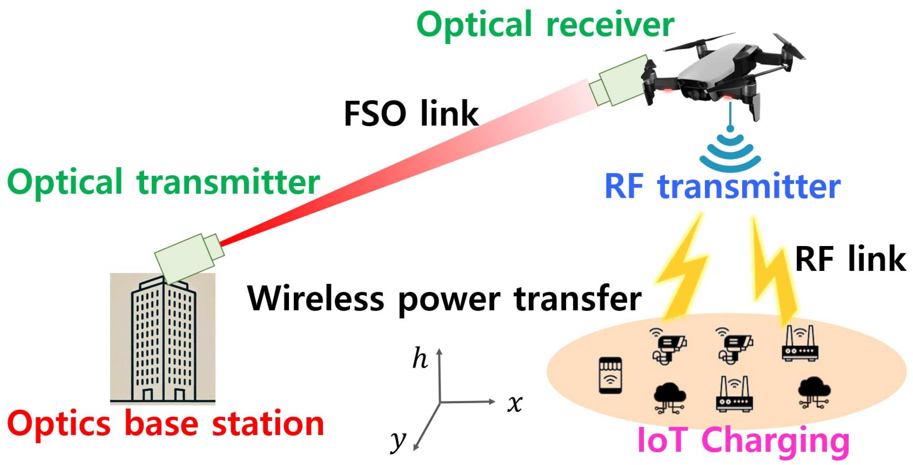
The rest of this paper is organized as follows. In Section 2, the related system models are introduced. In Section 3, the problem of jointly optimizing the divergence angle and UAV trajectory is formulated. In Section 4, we explore the PSO-based and the hybrid BS-PSO-based method to solve the problem. Our proposed methods are evaluated in Section 5, and a brief conclusion is drawn in Section 6.
2. System Model
Our system model is illustrated in Figure 1. We consider a free space optics (FSO)-based UAV-enabled relay system for wireless power transfer (WPT). The optical base station (OBS) transfers an optical power to the UAV via an FSO link. The UAV harvests optical signals and converts them into electrical signals, then transfers RF power to charge U energy harvesting devices (EHDs) on the ground via an RF link. Maintaining stable LoS visibility between the OBS and the UAV is crucial for providing reliable and sustainable power to the EHDs on the ground, as any disruption in the FSO link leads to an interruption in power transfer to the UAV. In this paper, it is assumed that the LoS is maintained between the OBS and the UAV. Let us denote as the three-dimensional coordinates of the OBS, where means the altitude of the OBS. Then, the 3-D locations of the UAV as well as the EHDs on the ground are represented as and , where , respectively.
Figure 1.
Illustration of FSO-based UAV-enabled wireless power transfer relay system model.
2.1. FSO Link Model Between the OBS and the UAV
By denoting as the transmit power of the optical beam at the FSO transmitter, the expected received optical power at the UAV, denoted as , becomes [20,21,22]
where and mean the optical converting efficiency between the electrical and optical power at the OBS FSO transmitter and UAV FSO receiver, respectively. According to the propagation of the optical beam, , , and indicate the atmospheric attenuation loss, turbulence-induced fading, and pointing and geometric loss, respectively [20,21]. Without loss of generality, it is assumed that for simplicity, where any constant values can be incorporated in our design problem. The amount of harvested energy from noise signals is ignored, as it is negligible compared to the transferred energy [1,20,21]. The details on , , and are as follows.
First, in atmospheric optical beam propagation, atmospheric attenuation is mainly caused by the scattering and absorption of particles that depend on the wavelength of the optical beam. By the Beer–Lambert law, can be modeled as [23]
where denotes the atmospheric attenuation factor in dB/km units, and () is the distance between the OBS and UAV in km units, where (with m units) is expressed as
In addition, the value of is determined by the visibility range and wavelength of the optical beam that is given by [23]
where V and are the visibility range in km units and the wavelength in nm units, respectively. In (4), 550 means the reference wavelength on the visibility range with nm units. is the scattering coefficient related to the particle size distribution, and its value can be determined using the Kim model as follows [20,23]:
Here, V depends on the weather conditions such that with clear weather and with foggy weather [20].
Second, fading in atmospheric optical beam propagation is caused by atmospheric turbulence that is primarily due to random fluctuations in air density and temperature. In this paper, we consider the Log-normal distribution to characterize weather conditions and atmospheric turbulence effects for the FSO link [23]. Then, the probability density function (PDF) of can be modeled as
where indicates the log-amplitude variance, and it is expressed as
where is the refractive index structure parameter that indicates the strength of atmospheric turbulence, and denotes the optical wave number. From (6), the expectation of is obtained as [21]
where means the error function.
At last, the details on the pointing and geometric loss are as follows. An acquisition, tracking, and pointing (ATP) system is widely adopted to precisely align a very narrow optical beam in the FSO link. However, beam misalignment may still occur due to mechanical imperfections in the ATP system and the mobility of the UAV with unavoidable mechanical vibrations [21,23,24]. By denoting as the the radial displacement of the optical beam at the FSO receiver, which means the distance between the center of the FSO receiver’s aperture and the center of the optical beam spot arrived at the FSO receiver, the pointing and geometric loss can be modeled as [21]
where indicates the divergence angle of the optical beam at the FSO transmitter, and means the radius of the FSO receiver’s aperture. In (9), represents the lower incomplete Gamma function, which is given by
In addition, the probability of the radial displacement can be modeled as the Rayleigh distribution [21,23,24], and its PDF is represented by
where means the variance in the radial displacement. From (9) and (11), the expectation of is obtained as [21]
where and are written by
Here, we notice that is not a monotonic function with respect to [21].
2.2. RF Link Model Between the UAV and the EHDs
Next, the UAV-enabled relay system transfers RF power to U EHDs by leveraging the received optical power from the OBS, i.e., . In this case, the harvested power at the u-th EHD becomes
where () is the energy harvesting efficiency at the u-th EHD, and is the average path loss (in dB units) for the u-th EHD’s RF link, where and denote the distance and elevation angle at the u-th EHD, respectively. Without loss of generality, we assume that for simplicity, where any constant values can be incorporated in our design problem. The details on are as follows.
For the aerial RF link, we consider the widely adopted air-to-ground (A2G) channel model, where a probability of having a line-of-sight (LoS) link for the u-th EHD depends on the elevation angle between the UAV and it [25,26,27]. Let and be the horizontal distance and distance between the UAV and u-th EHD, respectively, then and are expressed as
Then, the elevation angle (in radian units) between the UAV and u-th EHD, denoted by , is represented by
Here, we notice that and depend on the UAV location.
Moreover, the probability of having a LoS link for the u-th EH, denoted by , is the function of its elevation angle , and it is modeled by [25,26,27]
where and indicate the environmentally dependent (i.e., suburban, urban, dense urban, and highrise urban) parameters, respectively. Then, the average path loss depends on both and , and it is modeled as [25,26,27]
where and are the carrier frequency of the RF transmission and speed of light, respectively. In (20), and denote the environmental dependent average additional path loss for the LoS and NLoS in dB units, respectively.
3. Problem Formulation
According to (2), (8), (12), and (15), the average harvested power at the u-th EHD in the FSO-based UAV-enabled relay system for WPT is written by
where , , and are the functions with respect to the UAV location . Moving the UAV closer to the OBS reduces the distance between the OBS and UAV, i.e., , but increases the distances between the UAV and the EHDs, i.e., , and vice versa. In addition, the UAV location affects not only the distance of the u-th EHD but also its elevation angle that has an impact on the LoS probability . Furthermore, the pointing and geometric loss is affected by both the UAV location and the divergence angle at the OBS. Therefore, the UAV location and divergence angle need to be jointly optimized by taking account of all their interactions and their impact on the harvested power at the EHDs. To guarantee fairness in the harvested power among all EHDs, our design objective is to jointly optimize the divergence angle and the UAV trajectory to maximize the minimum harvested power among all devices. Hence, we formulate our design problem as follows:
where the constraints (22)–(24) mean the coverage of the UAV flight paths. Specifically, the constraints (22) and (23) with , , , and imply the allowable horizontal coverage, and the constraint (24) with and means the allowable altitude for the UAV in order to receive the optical beam from the OBS by avoiding obstacles or danger zones such as buildings [28]. In addition, the constraint (25) represents the divergence angle boundary, where and represent the minimum and maximum divergence angles at the FSO transmitter [21].
The objective function of the problem is a very complicated non-linear function as well as a non-convex one with respect to . Hence, it is extremely difficult to solve the problem in general. In the next section, we explore the Particle Swarm Optimization (PSO)-based method to find an optimal solution.
4. Joint Design of Divergence Angle of FSO Link and UAV Trajectory
We first introduce the basic idea and process of the PSO algorithm. Then, we develop the PSO-based algorithm to solve our design problem. Finally, we further devise the hybrid BS-PSO-based method to improve the optimization ability by leveraging the analysis on the optimal condition for the divergence angle.
4.1. Preliminary on Particle Swarm Optimization (PSO)
Particle Swarm Optimization (PSO) is a global optimization algorithm-based on swarm intelligence, commonly used as a meta-heuristic approach [11,28,29,30,31]. A group of particles, each with a position and velocity, explores the solution space to find the optimal solution by taking into account both its own best-discovered solution and the best solution found by the swarm as a whole. The particles iteratively update their positions and velocities while balancing exploration through individual learning and exploitation through cooperation with the whole swarm. This process is guided by a fitness function that helps refine the search path, leading to the best possible solution for optimizing the fitness function. Thanks to its efficiency with easy implementation, the PSO algorithm is widely used in various applications such as neural networks, function optimization, control, and so on [11,28,29,30,31]. Specifically, it has been extensively applied in the UAV trajectory and path planning optimizations. The details of the PSO algorithm for the L-dimensional optimization problem are as follows.
A swarm of M particles, where M denotes the total number of particles, navigates the L-dimensional variable space by updating the position of each particle at each iteration as follows:
where and indicate the position and velocity of m-th particle at the j-th iteration, respectively, where and , and J means the total number of iterations [11,28,29,30,31]. In this case, implies the rate of the next movement to update its new position. Specifically, by denoting the position of the best particle obtained in the m-th particle until the current iteration (i.e., ) as , and the position of the best particle among the whole swarm until the current iteration as , the PSO algorithm updates the velocity of the m-th particle at the j-th iteration as follows:
where represents the inertia weight, which controls the impact of momentum in the previous velocity. In addition, is a self-cognition coefficient for controlling the ability to learn from the particle itself, while is a coefficient that reflects the influence of the whole swarm on the particle. and imply the uniformly distributed random numbers in the range of , respectively. As in (27), each particle’s movement is guided by its local best known position, i.e., , as well as its global known position, i.e., , which is updated by other, better performing particles throughout all previous iterations [11,28,29,30,31].
4.2. Joint Design Based on the PSO Method
In the proposed PSO-based optimization, a swarm of particles means the four-dimensional vector (i.e., ), which is composed of the UAV location and divergence angle. Thus, the position vector of the m-th particle at the j-th iteration is represented as
In (28), each element of the position vector must satisfy the constraints (22)–(25) such that
where and are the l-th element of and , respectively, and and are given, respectively, as
To find an optimal solution of the problem , the objective function of the problem becomes the fitness function of the proposed PSO algorithm. By denoting as the fitness function, it is expressed as
Then, is iteratively updated for increasing the fitness function , and the PSO algorithm is terminated when does not improve for a certain number of iterations. Finally, we obtain an best solution for maximizing .
The detailed procedure is described in Algorithm 1. Lines 3–7 describe the initialization of the velocity and the position satisfying the constraint (29), as well as the initialization of , for all particles. Also, Line 8 means the initialization of according to the fitness function (30). Lines 10–22 describe the update of velocity and position while satisfying the constraint (29), as well as based on the fitness function (30). Line 23 denotes the update of to maximize the fitness function among the whole swarm. Lines 24–29 describe the termination of the PSO algorithm when the rate of change in the fitness function, i.e., , does not improved for a certain number iterations with a pre-determined tolerance , where and represent the previous and current fitness values, and means the pre-determined maximum number of iterations for non-improved termination.
| Algorithm 1 Algorithm of the PSO-based optimization. |
|
4.3. Proposed Hybrid BS-PSO Method for Joint Design
In this subsection, driven by the optimal condition of with a given , we devise the hybrid BS-PSO-based optimization method to enhance the optimization ability in a conventional PSO algorithm that falls into a local solution and slow convergence [28,29,30,31] as follows.
First, from (12), the upper bound of can be obtained by
where (31) comes from the fact that and in (13) and (14), respectively. Then, from (31), the first partial derivative of with respect to is obtained by
where is represented as
Both and its first derivative are very complicated non-linear functions with respect to , but the optimal solution of must satisfy either
In (34), it is readily verified that is equivalent to from (32). We notice that that satisfies – can be obtained by the well-known Bisection (BS) line-search method [32]. In this case, the upper bound of the average harvested power at the u-th EHD becomes
According to the optimal condition for , we devise the hybrid BS-PSO algorithm that explores the PSO algorithm to find an optimal , while utilizing the Bisection method to find an optimal . In the proposed hybrid BS-PSO algorithm, a swarm of particles becomes the three-dimensional vector (i.e., ), and then the position vector of the m-th particle at the j-th iteration is represented as
In addition, in (3) is rewritten as
The detailed procedure of the proposed hybrid BS-PSO method is described in Algorithm 2. Line 4 means the initialization , , and , same as in Algorithm 1. Line 6 describes the procedure to obtain with a given based on the Bisection method, that is described in Algorithm 3. For the hybrid BS-PSO method, according to (35), the fitness function becomes
where is the obtained value from the Bisection method with a given . Line 7 computes the fitness function for the initialization. Also, Line 9 describes the initialization of as well as to maximize the fitness function (38). Lines 13–15 describe the update of with its velocity as well as corresponding that is obtained from the Bisection method with a given . In addition, Lines 16–18 mean the update of as well as corresponding for increasing the fitness function. Line 20 implies the update of both and to maximize the fitness function among the whole swarm. Line 21 means the termination of the proposed hybrid BS-PSO method, same as in Algorithm 1.
| Algorithm 2 Algorithm of the hybrid BS-PSO-based optimization. |
|
| Algorithm 3 The Bisection line-search method to find . |
|
5. Numerical Results
In this section, we numerically evaluate our proposed joint design. This paper explores the significance of theoretical analysis and optimization in understanding and enhancing complex systems. The proposed method and numerical results validate its capability to predict scenarios and tackle challenges, offering substantial reductions in experimentation time and cost. Extending the proposed method to experimental validation for practical implementation remains one of our ongoing research topics. By referring to the previous works [10,11,19,21,25,26,27,30,31], we consider the simulation settings listed in Table 1.
Table 1.
Simulation settings.
5.1. Performance Evaluation in a Single-EHD Scenario
First, we consider a single EHD scenario, i.e., , when the visibility range is 50 km, i.e., km. Figure 2 compares the received power at the UAV by varying the divergence angle for different distances between the OBS and UAV as well as the different variance in the radial displacement. For comparison, we consider that the variance in the radial displacement is , and the UAV horizontal location is m with , respectively. Obviously, the received power at the UAV is not a monotonic function with respect to the divergence angle, and the value is maximized at rad when , rad when , rad when , and rad when , respectively. Figure 2 verifies that the divergence angle to maximize the received power at the UAV depends on the variance in the radial displacement as well as the UAV location.
Figure 2.
Received power at the UAV with respect to the divergence angle when km.
5.2. Performance Evaluation in a Multiple-EHD Scenario
Next, we evaluate our proposed methods in a multiple-EHD scenario. We consider 32 EHDs, i.e., , which are uniformly distributed in a rectangular area on a horizontal plane with dimensions of 200 m × 200 m as illustrated in Figure 3. For performance comparison, by denoting and as the average value of and , respectively, we consider the following six methods:
Figure 3.
Illustration of simulation setup.
- Reference Method-1: and .
- Reference Method-2: and .
- Reference Method-3: and .
- Reference Method-4: and .
- Proposed Method-1: Obtained from Algorithm 1.
- Proposed Method-2: Obtained from Algorithm 2.
- Optimal Method: Optimal UAV trajectory and divergence angle obtained by 3-D exhaustive line-search method with BS line-search method.
The reference methods mean the fixed UAV location and divergence angle, while the proposed methods obtain the optimal UAV location and divergence angle from Algorithms 1 and 2, respectively. For the optimal method, we adopt the 3-D exhaustive line-search method to find an optimal solution of rather than the PSO method. We set the sample grid accuracy to 0.5 m for each line search.
To examine our proposed methods in various environments, we compare the minimum harvested power among all devices, by varying the variance in the radial displacement, the horizontal distance between the OBS and the center of the rectangular area (denoted as ), and the visibility range, respectively.
5.2.1. Performance Evaluation by Varying the Variance in the Radial Displacement
Figure 4 compares the minimum harvested power of various methods with respect to the variance in the radial displacement (i.e., ) when km and km. As shown, the proposed methods significantly increase the minimum harvested power compared to the reference methods and achieve the optimal performance. Moreover, the harvested power decreases as the variance increases. This is because as the variance increases, the displacement of the optical beam spot reaching at the UAV increases, thereby decreasing the received power at the UAV.
Figure 4.
The minimum harvested power of various methods with respect to the variance in the radial displacement (i.e., ) when km and km.
As such, Figure 5a,b depict the optical divergence angle obtained from each algorithm and the corresponding execution time, respectively, by varying the variance in the radial displacement (i.e., ) when km and km. The optimal divergence angle increases as the variance increases. The proposed methods yield similar divergence angles compared to the optimal method. Obviously, Figure 5b demonstrates that the proposed methods considerably reduce the execution time compared to the optimal method. Moreover, Proposed Method-2 yields a smaller execution time compared to Proposed Method-1.
Figure 5.
Performance comparison between Proposed Method-1 and Proposed Method-2 with respect to the variance in the radial displacement (i.e., ) when km and km.
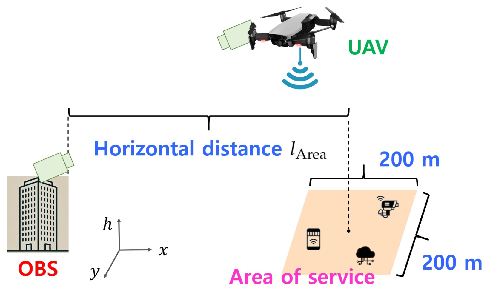
5.2.2. Performance Evaluation by Varying the Horizontal Distance from the Center
Figure 6 compares the minimum harvested power of various methods with respect to the horizontal distance from the center (i.e., ) when and km. As expected, the proposed methods considerably outperform the reference methods and achieve the optimal performance in all ranges. It is shown that the minimum harvested power of the reference methods varies according to the horizontal distance, while the harvested power of the proposed methods is barely affected by the distance. The reason is that the visibility range is km, resulting in atmospheric attenuation that is comparable within the range of km, while the divergence angle and UAV trajectory are optimized accordingly.
Figure 6.
The minimum harvested power of various methods with respect to the horizontal distance from the center (i.e., ) when and km.
As such, Figure 7a–c illustrate the optical divergence angle, optimal UAV trajectory, and corresponding execution time obtained from each algorithm, respectively, when and km. The optimal divergence angle decreases as the horizontal distance increases. Meanwhile, it is shown that the proposed methods achieve the optimal divergence angle as well as similar UAV trajectory over the optimal method. As expected, the proposed methods significantly reduce the execution time compared to the optimal method, and Proposed Method-2 achieves the smallest execution time in all ranges.
Figure 7.
Performance comparison between Proposed Method-1 and Proposed Method-2 with respect to the horizontal distance from the center (i.e., ) when and km.
Next, we evaluate the minimum harvested power of various methods for different visibility ranges, i.e., km.
Figure 8 compares the minimum harvested power of various methods with respect to the horizontal distance from the center (i.e., ) when and km. The proposed methods outperform the reference methods, and achieve the optimal performance. In particular, the minimum harvested power non-linearly decreases as the horizontal distance increases. This is because the visibility range is km, which lies within the range of km. Therefore, as the horizontal distance increases, atmospheric attenuation significantly increases, further highlighting the impact of reduced visibility on the signal propagation.
Figure 8.
The minimum harvested power of various methods with respect to the horizontal distance from the center (i.e., ) when and km.
As such, Figure 9a–c illustrate the optical divergence angle, optimal UAV trajectory, and corresponding execution time obtained from each algorithm, respectively, when and km. As expected, it is shown that the proposed methods achieve the near-optimal divergence angle and UAV trajectory while significantly reducing the execution time. Meanwhile, as shown in Figure 9a, the optimal divergence angle for km is similar to the optimal divergence angle for km as depicted in Figure 7a. This is because the visibility range affects only the atmospheric attenuation in the FSO link.
Figure 9.
Performance comparison between Proposed Method-1 and Proposed Method-2 with respect to the horizontal distance from the center (i.e., ) when and km.
6. Conclusions
This paper proposed a joint design of the divergence angle and UAV trajectory for FSO-based UAV-enabled WPT relay systems. We characterized that the harvested power at the ground devices is affected by the divergence angle at the FSO transmitter as well as the UAV trajectory that impacts both the FSO link and RF link at the same time. We formulated the design problem to maximize the minimum harvested power among all devices, and developed the PSO-based method to solve the non-convex and highly non-linear problem. By investigating the optimal condition for the divergence angle, we further proposed the BS-PSO-based method to enhance the optimization ability. The proposed method was shown to significantly increase the harvested power as well as improving the optimization capability in terms of the execution time compared to the conventional algorithm.
Funding
This work was supported in part by the NRF (National Research Foundation of Korea) grant funded by the Korea government (Ministry of Science and ICT) (RS-2023-00214142), and in part by the research grant of the Gyeongsang National University in 2022.
Data Availability Statement
Data are contained within the article.
Conflicts of Interest
The author declares no conflicts of interest.
References
- Kang, J.; Choi, J.; Choi, W. Multi-User Energy Beamforming for Different Energy Requests. IEEE Wirel. Commun. Lett. 2021, 10, 1687–1691. [Google Scholar] [CrossRef]
- Xie, L.; Cao, X.; Xu, J.; Zhang, R. UAV-Enabled Wireless Power Transfer: A Tutorial Overview. IEEE Trans. Green Commun. Net. 2021, 62, 2042–2064. [Google Scholar] [CrossRef]
- Che, Y.; Zhao, Z.; Luo, S.; Wu, K.; Duan, L.; Leung, V.C.M. UAV-Aided Wireless Energy Transfer for Sustaining Internet of Everything in 6G. Drones 2023, 7, 628. [Google Scholar] [CrossRef]
- Xu, J.; Zeng, Y.; Zhang, R. UAV-Enabled Wireless Power Transfer: Trajectory Design and Energy Optimization. IEEE Trans. Wirel. Commun. 2018, 17, 5092–5106. [Google Scholar] [CrossRef]
- Hu, Y.; Yuan, X.; Xu, J.; Schmeink, A. Optimal 1D Trajectory Design for UAV-Enabled Multiuser Wireless Power Transfer. IEEE Trans. Commun. 2019, 67, 5674–5688. [Google Scholar] [CrossRef]
- Yuan, X.; Yang, T.; Hu, Y.; Xu, J.; Schmeink, A. Trajectory Design for UAV-Enabled Multiuser Wireless Power Transfer with Nonlinear Energy Harvesting. IEEE Trans. Wirel. Commun. 2021, 20, 1105–1121. [Google Scholar] [CrossRef]
- Gou, X.; Sun, Z.; Huang, L. UAV-Aided Dual-User Wireless Power Transfer: 3D Trajectory Design and Energy Optimization. Sensors 2023, 23, 2994. [Google Scholar] [CrossRef]
- Yuan, X.; Hu, Y.; Schmeink, A. Joint Design of UAV Trajectory and Directional Antenna Orientation in UAV-Enabled Wireless Power Transfer Networks. IEEE J. Sel. Areas Commun. 2021, 39, 3081–3096. [Google Scholar] [CrossRef]
- Yuan, X.; Jiang, H.; Hu, Y.; Schmeink, A. Joint Analog Beamforming and Trajectory Planning for Energy-Efficient UAV-Enabled Nonlinear Wireless Power Transfer. IEEE J. Sel. Areas Commun. 2022, 40, 2914–2929. [Google Scholar] [CrossRef]
- Kang, J. Joint Design of Altitude and Channel Statistics based Energy Beamforming for UAV-enabled Wireless Energy Transfer. Drones 2024, 8, 668. [Google Scholar] [CrossRef]
- Kang, J. Joint Design of Transmit Waveform and Altitude for UAV-enabled Integrated Sensing and Wireless Power Transfer Systems. Electroncis 2024, 13, 4237. [Google Scholar]
- Mu, J.; Sun, Z. Trajectory Design for Multi-UAV-Aided Wireless Power Transfer toward Future Wireless Systems. Sensors 2022, 22, 6859. [Google Scholar] [CrossRef] [PubMed]
- Wang, X.; Wu, P.; Hu, Y.; Cai, X.; Song, Q.; Chen, H. Joint Trajectories and Resource Allocation Design for Multi-UAV-Assisted Wireless Power Transfer with Nonlinear Energy Harvesting. Drones 2023, 7, 354. [Google Scholar] [CrossRef]
- Kaymak, Y.; Rojas-Cessa, R.; Feng, J.; Ansari, N.; Zhou, M.; Zhang, T. A Survey on Acquisition, Tracking, and Pointing Mechanisms for Mobile Free-Space Optical Communications. IEEE Commun. Surv. Tutor. 2018, 20, 1104–1123. [Google Scholar] [CrossRef]
- Hamza, A.S.; Deogun, J.S.; Alexander, D.R. Classification Framework for Free Space Optical Communication Links and Systems. IEEE Commun. Surv. Tutor. 2019, 21, 1346–1382. [Google Scholar] [CrossRef]
- Elamassie, M.; Uysal, M. Free Space Optical Communication: An Enabling Backhaul Technology for 6G Non-Terrestrial Networks. Photonics 2023, 10, 1210. [Google Scholar] [CrossRef]
- Nzekwu, N.J.; Fernandes, M.A.; Fernandes, G.M.; Monteiro, P.P.; Guiomar, F.P. A Comprehensive Review of UAV-Assisted FSO Relay Systems. Photonics 2024, 11, 274. [Google Scholar] [CrossRef]
- Khalighi, M.A.; Uysal, M. Survey on Free Space Optical Communication: A Communication Theory Perspective. IEEE Commun. Surv. Tutor. 2014, 16, 2231–2258. [Google Scholar] [CrossRef]
- Kaushal, H.; Kaddoum, G. Optical Communication in Space: Challenges and Mitigation Techniques. IEEE Commun. Surv. Tutor. 2017, 19, 57–96. [Google Scholar] [CrossRef]
- Wu, D.; Sun, X.; Ansari, N. An FSO-Based Drone Charging System for Emergency Communications. IEEE Trans. Veh. Tech. 2020, 69, 16155–16162. [Google Scholar] [CrossRef]
- Zhang, T.; Sun, X.; Wang, C. On Optimizing the Divergence Angle of an FSO-Based Fronthaul Link in Drone-Assisted Mobile Networks. IEEE Internet Things J. 2022, 9, 6914–6921. [Google Scholar] [CrossRef]
- Yu, L.; Sun, X.; Shao, S.; Chen, Y.; Albelaihi, R. Backhaul-Aware Drone Base Station Placement and Resource Management for FSO-Based Drone-Assisted Mobile Networks. IEEE Trans. Net. Sci. Eng. 2023, 10, 1659–1668. [Google Scholar] [CrossRef]
- Gupta, A.; Dhawan, D.; Gupta, N. Review on UAV-based FSO links: Recent advances, challenges, and performance metrics. Optical Eng. 2024, 63, 41204. [Google Scholar] [CrossRef]
- Singh, D.; Swaminathan, R. Comprehensive performance analysis of hovering UAV-based FSO communication system. IEEE Photonics J. 2022, 14, 7352013. [Google Scholar] [CrossRef]
- Al-Hourani, A.; Kandeepan, S.; Lardner, S. Optimal LAP Altitude for Maximum Coverage. IEEE Wirel. Commun. Lett. 2014, 3, 569–572. [Google Scholar] [CrossRef]
- Khuwaja, A.A.; Chen, Y.; Zhao, N.; Alouini, M.-S.; Dobbins, P. A Survey of Channel Modeling for UAV Communications. IEEE Commun. Surv. Tutorials 2018, 20, 2804–2821. [Google Scholar] [CrossRef]
- Al-Hourani, A.; Gomez, K. Modeling cellular-to-UAV path-loss for suburban environments. IEEE Wirel. Commun. Lett. 2018, 7, 82–85. [Google Scholar] [CrossRef]
- Yu, Z.; Si, Z.; Li, X.; Wang, D.; Song, H. A Novel Hybrid Particle Swarm Optimization Algorithm for Path Planning of UAVs. IEEE Internet Things J. 2022, 9, 22547–22558. [Google Scholar] [CrossRef]
- Shi, L.; Xu, S. UAV Path Planning with QoS Constraint in Device-to-Device 5G Networks Using Particle Swarm Optimization. IEEE Access 2020, 8, 137884–137896. [Google Scholar] [CrossRef]
- Sonny, A.; Yeduri, S.R.; Cenkeramaddi, L.R. Autonomous UAV Path Planning Using Modified PSO for UAV-Assisted Wireless Networks. IEEE Access 2023, 11, 70353–70367. [Google Scholar] [CrossRef]
- Zhang, W.; Zhang, W. An Efficient UAV Localization Technique Based on Particle Swarm Optimization. IEEE Trans. Veh. Tech. 2022, 71, 9544–9557. [Google Scholar] [CrossRef]
- Kang, J.; Choi, W. Novel Codebook Design for Channel State Information Quantization in MIMO Rician Fading Channels with Limited Feedback. IEEE Trans. Signal Process. 2021, 69, 2858–2872. [Google Scholar] [CrossRef]
Disclaimer/Publisher’s Note: The statements, opinions and data contained in all publications are solely those of the individual author(s) and contributor(s) and not of MDPI and/or the editor(s). MDPI and/or the editor(s) disclaim responsibility for any injury to people or property resulting from any ideas, methods, instructions or products referred to in the content. |
© 2024 by the author. Licensee MDPI, Basel, Switzerland. This article is an open access article distributed under the terms and conditions of the Creative Commons Attribution (CC BY) license (https://creativecommons.org/licenses/by/4.0/).