Abstract
The crosstalk of the small detection photosensitive elements test has always been the difficulty of research on infrared focal plane arrays (IRFPAs). With the decrease in the element size in the IRFPAs, the crosstalk of small detection photosensitive elements cannot be tested by the existing small spot method. In this paper, a novel eye hole method to realize the crosstalk of the small element IRFPAs test is proposed. The novel eye hole method is to make eye holes on the substrate. The transmittance of the eye holes in the substrate is 100%, while the transmittance of the other component in the substrate is 0. The substrate with the eye holes is fixed in front of small element IRFPAs to achieve the crosstalk of the small elements test. The filters selected by 9 elements and 25 elements as the eye hole unit are designed and prepared. The experimental results show that 25 elements are selected as the eye hole unit for the IRFPAs with the element size of 25 μm × 25 μm. The eye holes are formed tightly and repeatedly arranged. The crosstalk of the InSb IRFPAs with the element size of 25 μm × 25 μm by the novel eye hole method is 3.86%. The results are of great reference significance for improving the test level of small element IRFPA.
1. Introduction
Infrared focal plane arrays (IRFPAs) have the advantages of high sensitivity, good environmental adaptability, and strong anti-interference. They are widely used by the military and civilians as defense weapons and for infrared remote sensing and the meteorological environment [1,2,3,4,5,6,7,8,9]. The small element IRFPAs have always been a research hotspot at both home and abroad [10,11,12,13]. In order to improve the spatial resolution, large-scale IRFPAs have been developed, but this brings the issues of the increased power consumption and cost of the system. In order to reduce the power consumption and overall cost of the system, the small element IRFPAs have been developed. With the decrease in the element size in the IRFPAs, the crosstalk of small detection photosensitive elements cannot be tested by the existing small spot method. The crosstalk of the small detection photosensitive elements test has always been the difficulty of research on IRFPAs. However, the crosstalk is one of the important indicators of IRFPAs [14,15,16,17,18,19,20,21]. The crosstalk of small element IRFPAs will seriously affect the spatial resolution of the IRFPAs, and their spatial resolution directly affects the imaging quality of the system. Therefore, in the infrared imaging system, the crosstalk will reduce the clarity of the image, leading to cause the system performance attenuation. The normally detection photosensitive element of the IRFPAs has a string disturbance for its adjacent elements, which is called crosstalk. The main component of the crosstalk is the horizontal diffusion of the photogenerated carrier between the detection photosensitive element and its adjacent elements of IRFPAs. Therefore, the crosstalk between the detection photosensitive element and its adjacent elements in the small element IRFPAs is unavoidable. At present, the crosstalk is tested by the small spot method to obtain response data and then determine the crosstalk between the detection photosensitive element and its adjacent elements. However, there are two problems when the crosstalk of the small element IRFPAs is tested by the existing small spot method.
One issue is that the size of the detection photosensitive element must be within the test level to obtain the normal crosstalk. The crosstalk of the small element IRFPAs cannot be tested by the existing small spot method when the element size has exceeded the test level. The small spot method for crosstalk testing is mainly to bring the point blackbody radiation through the small hole and converge into the measured detection photosensitive element, and then evaluate its crosstalk to the adjacent elements. In the actual test, it is found that when the diameter of the small hole is below 5 μm, the small hole cannot be imaged on the imaging diagram, and the debugging alignment of the element requires a reference to the actual measurement image. Therefore, the diameter of the small hole needs to be selected at 10 μm. In this case, the light spot exceeds 25 μm, according to the existing gathering optical system in the actual test. Therefore, the existing small spot method cannot test the crosstalk of IRFPAs with the size of an element less than or equal to 25 μm.
The other issue is that the small hole and the detection photosensitive element need to be accurately aimed at during testing. The debugging is difficult and time-consuming. Although the crosstalk of a small amount of extraction detection photosensitive elements can replace the crosstalk of the level of the overall device, it is still necessary to test the extraction detection photosensitive elements one by one, and the workload is also large. In summary, the crosstalk of the small element IRFPAs cannot be tested by the existing small spot method. The lack of the crosstalk detection method of the small element IRFPAs seriously affects the application of infrared systems. In this paper, a novel eye hole method to realize the crosstalk of the small element IRFPAs test through the response voltage of the IRFPAs test is proposed. At the same time, the InSb IRFPAs with the element size of 50 μm × 50 μm and 25 μm × 25 μm are designed and tested. The feasibility of the novel eye hole method is verified though the comparison of the crosstalk test data for InSb IRFPAs with the element size of 50 μm × 50 μm by the small spot method and the novel eye hole method. Then, the crosstalk of the InSb IRFPAs with the element size of 25 μm × 25 μm is tested by the novel eye hole method. The results are of great reference significance for improving the test level of small element IRFPAs.
2. Analysis of a Novel Eye Hole Method and Small Element IRFPAs Application
2.1. Analysis of Eye Hole Units Design
The novel eye hole method is to make eye hole units on the substrate. Then, the substrate with the eye hole units is fixed in front of IRFPAs to achieve the crosstalk of the small element IRFPAs test. The design, preparation, and application of eye hole units are analyzed.
(1) Design and analysis of a single eye hole unit
The easiest way to realize the crosstalk detection for small element IRFPAs is to test the crosstalk of the single detection photosensitive element with a single eye hole unit. This scheme is easy to implement, and there is no need to consider the crosstalk of the surrounding detection photosensitive elements. The single eye hole unit is to make an eye hole on the substrate. The transmittance of the eye hole in the substrate is 100%, while the transmittance of the other component in the substrate is 0.
But the disadvantage of this method is that it can only test the crosstalk of a single detection photosensitive element each time. In order to obtain the crosstalk of multiple detection photosensitive elements, it is necessary to make multiple substrates of the single eye hole unit and conduct multiple alignment tests. The contrastability of the test data decreases with multiple clamping treatments of the IRFPAs. The method not only cannot guarantee the accuracy of the test data, but also needs to make multiple substrates of the single eye hole unit with different locations, so as to test multiple crosstalk data for analysis and processing and to exclude the effects of abnormal data.
The optimized crosstalk detection method for small element IRFPAs is to closely arrange the graphics of the single eye hole unit or arrange it as needed. This method is also easy to implement. It is conducive to subsequent data processing analysis, and accurate crosstalk test results can be obtained because the crosstalk of each eye hole unit is obtained under the same test condition. However, this method needs to consider the number of detection photosensitive elements contained in the graphic of the eye hole unit. It needs to be designed to eliminate the string of the measured eye hole to the adjacent eye hole to ensure the accuracy and effectiveness of the crosstalk. Therefore, the crosstalk of a single eye hole unit test is analyzed. The smallest eye hole unit is determined according to the test results.
The central opening has full transmittance (the transmittance is close to 100%) and the surrounding full cutoff (the transmittance is 0). Under normal circumstances, the response voltage of the single eye hole is normal when it is fully penetrated at the central opening, and 0 when it is fully cut off at the surrounding area. It not only avoids interference from other eye holes, but also allows for clear and accurate test results. In Figure 1, the black represents the full cutoff, and the white represents the full transmission.

Figure 1.
The eye hole unit with 9 elements.
(2) Design and analysis of eye hole units for experiments
The eye hole units for experiments can be tightly arranged or arranged according to the need. The crosstalk of the eye hole unit graphic obtained by the novel eye hole method is obtained under the same test condition. It can not only solve the need to make multiple substrates with the single eye hole unit to align the test to obtain multiple crosstalk data, but also acquire multiple crosstalk test results at the same time, increasing the accuracy and comparability of the data.
There are two options for the eye hole unit. One is to select 9 detection elements in the box as the eye hole unit, as shown in Figure 1. The other is to select 25 detection elements in the box as the eye hole unit, as shown in Figure 2. Regardless of which method is selected, it is necessary to ensure that the crosstalk between the adjacent eye hole units and the tested eye hole unit is close to zero. It is conducive to obtaining the experimental data of 9 detection elements and 25 detection elements as the eye hole unit at the same time, and then obtaining the optimal eye hole unit for a lithography pattern through results analysis.

Figure 2.
The eye hole unit with 25 elements.
2.2. Eye Hole Units Preparing
In the design scheme, the transmittance full cutoff can be achieved by adopting a black opaque coating, or by using the growth gold film blocking radiation. Considering the controllability of the eye hole size and the feasibility of the operation, and the subsequent eye hole units’ preparation, the latter’s preparation method is selected here. For the fully transparent eye hole, it is only necessary to consider choosing substrate materials with a high infrared transmittance rate, so that the transmittance of the eye hole is close to 100%. The preparation of substrates with eye hole units can be corroded or stripped. The preparation process includes the following: the selection and pre-processing of the substrate, the growth of gold film, and the preparation of eye hole units. Quartz glass is used as the substrate and cleaned using a standard method. In order to ensure the high pass rate of the quartz glass within the range of (3.7 μm~4.8 μm), the quartz glass is polished to less than 150 μm. The deadline of the quartz glass is extended to 4.8 μm. The gold film on the surface of the substrate is grown using ultra-vacuum magnetic sputtering equipment, with a thickness of 0.1 μm.
2.3. Method Application
The experimental sample InSb arrays are first processed as follows: an n-type InSb substrate is used, a P-type layer is obtained through the diffusion Cd, and a surface with mesa is obtained by photolithography and etching. After the passivation of the mesa, a chrome gold layer is evaporated and then electrodes are obtained through photolithography and corrosion processes. The InSb arrays with 50 μm × 50 μm and 25 μm × 25 μm are designed and prepared. After the chips are prepared, the developed InSb arrays and the readout circuit arrays are photolithographed with indium column windows and evaporated with indium film at the same time. The indium column arrays are obtained through a stripping process, and then connected through flip-chip bonding. The flip-chip bonding devices are assembled and encapsulated after bottom filling, thinning polishing, and the vapor deposition of anti-reflection film. The InSb IRFPA is shown in Figure 3.
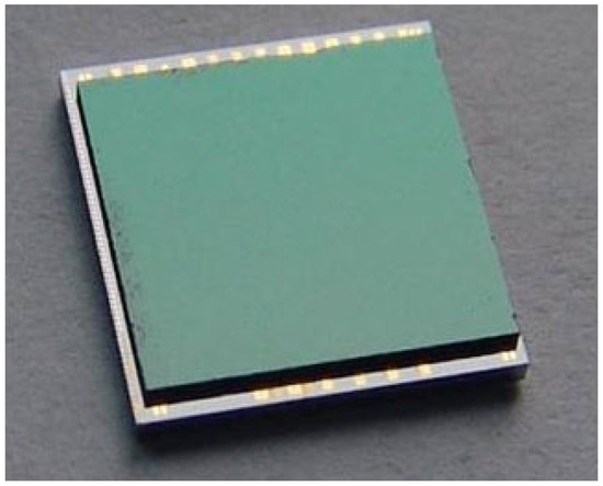
Figure 3.
The image of InSb IRFPA.
The small light point method and the novel eye hole method are used to test the crosstalk of InSb IRFPA with the element size of 50 μm × 50 μm in the same coordinate point detection photosensitive element, respectively. Then, the novel eye hole method is used to test the crosstalk of InSb IRFPAs with the element size of 25 μm × 25 μm. According to the above methods, two substrates with eye hole units are designed and prepared.
The prepared substrates with eye hole units are installed in front of the IRFPAs. Each eye hole unit is aligned with each photosensitive element of the IRFPAs. The schematic diagram of the alignment structure is shown in Figure 4. The IRFPAs with the eye hole unit are subsequently tested by the IRFPAs test system. The obtained test data of the response voltage are converted into the test data of the crosstalk, and the crosstalk of small element IRFPAs is analyzed.
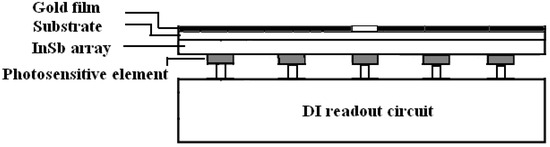
Figure 4.
Element alignment configuration.
3. Result and Discussion
3.1. Verification of the Novel Eye Hole Method
In order to verify the feasibility of the novel eye hole method, the crosstalk of InSb IRFPAs with the size of 50 μm × 50 μm is tested in the small spot method and the novel eye hole method, respectively. The working temperature of InSb IRFPAs is 77 K. The crosstalk test conditions for InSb IRFPAs with the size of 50 μm × 50 μm by the small spot method are as follows: point blackbody is used. The room temperature is 300 K. The working temperature of the point blackbody is 1000 K. The working wave band is 3~5 μm. The diameter of the hole of the diaphragm is 10 μm. The distance between the hole of the diaphragm and photosensitive detector is 30 μm. The crosstalk test conditions for InSb IRFPAs with the size of 25 μm × 25 μm by the novel eye hole method are as follows: surface blackbody is used. The room temperature is 300 K. The working temperature of the surface blackbody is 305 K. A comparison of the crosstalk test conditions for InSb IRFPAs with the size of 50 μm × 50 μm by the small spot method and the novel eye hole method is shown in Table 1.

Table 1.
Comparison of the crosstalk test conditions for InSb IRFPAs with the size of 50 μm × 50 μm by the small spot method and the novel eye hole method.
Under the above test conditions, the crosstalk test of InSb IRFPAs with the size of 50 μm × 50 μm is completed and the test results are shown in Table 2. From Table 2, it can be seen that, according to the conventional small spot method, the crosstalk mainly refers to the average value of the crosstalk between the measured photosensitive element and its adjacent elements. The schematic diagram of the crosstalk test is shown in Figure 5. When the small light dot light source is incident in the center of the photosensitive element in the i-th line and j-th column, the signal Vs(i, j) of the photosensitive element is measured, and the signals VS(i ± 1, j) and VS(i, j ± 1) of the four adjacent elements which are above, below, left, and right of the photosensitive element are also measured at the same time. Then, the crosstalk between the four adjacent elements and the photosensitive element is calculated by the following formula:
Table 2.
Parameters of the crosstalk of coordinate point (94, 85) in the IRFPA by the small spot method.
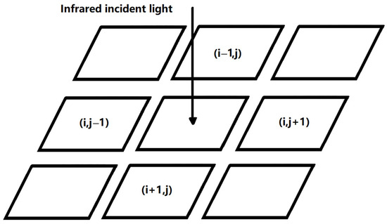
Figure 5.
The schematic diagram of the crosstalk test.
The average crosstalk between the four adjacent elements and the photosensitive element is
According to Formula (3), the crosstalk at the coordinate point here is the average of the sum of the crosstalk among the upper, lower, left, and right detection elements. According to the calculation of the test data in Table 2, the crosstalk at coordinate point (94, 85) of a certain photosensitive element is 3.11%. Table 3 shows the experimental data of the response voltage of the eye hole point (94, 85) tested by the novel eye hole method. According to the crosstalk Formulas (1) and (2), corresponding to the experimental data of the response voltage in Table 3, the experimental data in Table 4 are the crosstalk data of the eye hole unit at the corresponding detection photosensitive element coordinate points (94, 85).
Table 3.
Response voltage of the eye hole point (94, 85) in the IRFPA by the novel eye hole method.
Table 4.
Crosstalk of the eye hole point (94, 85) in IRFPA by the novel eye hole method.
From Table 4, it can be seen that after using the novel eye hole method, the crosstalk of the IRFPAs can be obtained significantly. According to the Formula (3), the crosstalk of a single eye hole point which can be calculated from the test data in Table 3 is 2.98%. From Table 2 and Table 4, it can be seen that, after actual testing, the crosstalk of the InSb IRFPAs with the element size of 50 μm × 50 μm is basically same under the small light dot method and the novel eye hole method. It fully verifies the feasibility of using the novel eye hole method for the crosstalk test of IRFPAs.
3.2. The Novel Eye Hole Method for the Crosstalk Test of Small Element IRFPAs
The crosstalk of InSb IRFPAs with the element size of 25 μm × 25 μm is tested by the IRFPAs test system. Table 5 shows the experimental data of the response voltage of the eye hole units at the randomly selected eye hole point (313, 249) in the InSb IRFPAs with the element size of 25 μm × 25 μm tested by the eye hole method. Corresponding to the experimental data of the response voltage in Table 5, the experimental data of the crosstalk of the eye hole point (313, 249) in the InSb IRFPAs with the element size of 25 μm × 25 μm is shown in Table 6. From Table 6, it can be seen that, after using the novel eye hole method, the crosstalk of the InSb IRFPAs with 25 μm × 25 μm can be obtained significantly. The crosstalk of a single eye hole point in the InSb IRFPAs with 25 μm × 25 μm, which can be calculated from the test data of the response voltage in Table 6, is 3.86%.
Table 5.
Response voltage of eyelet point (313, 249) in the IRFPAs with the size of 25 μm × 25 μm by the novel eye hole point method.
Table 6.
Crosstalk of eye hole point (313, 249) in the IRFPAs with the size of 25 μm × 25 μm by the novel eye hole method.
From Table 6, it can also be seen that the crosstalk values of the upper, lower, left, and right elements in the inner frame are basically close, and compared with other values, they are obviously very large. It shows that the eye hole unit mainly affects the detection photosensitive elements in the inner frame. The crosstalk of the photosensitive elements outside of the outer frame is basically 0. It shows that the impact of the eye hole element on the detection photosensitive elements outside of the outer frame is almost 0. The maximum test data value of the crosstalk between the inner frame and the outer frame can reach 0.93%, which is about 23% compared to the maximum value of 4.1% in the inner frame. It shows that the detection photosensitive element has an impact on the detection elements between the inner frame and outer frame, and it cannot be ignored. Further analysis of the test results shows that the crosstalk of IRFPAs can be obtained, although the 9 detection elements in the inner frame serve as the eye hole unit. But the test data are still affected by the adjacent eye hole unit. The impact of each adjacent eye hole unit is almost 0 when the 25 detection elements in the outer frame, as shown in the figure, are taken as the eye hole unit. Therefore, it is necessary to select 25 detection elements, as shown in the figure as the eye hole unit.
4. Conclusions
With the decrease in the element size of IRFPAs, the crosstalk of small elements cannot be tested by the existing small spot method. In response to the problem, the novel eye hole method to realize the crosstalk of small element IRFPAs test is proposed. The experimental results show that the crosstalk of the InSb IRFPAs with the element size of 50 μm × 50 μm is basically the same under the small light dot method and the novel eye hole method. The 25 detection elements are selected as the eye hole unit when the crosstalk of the InSb IRFPAs with the element size of 25 μm × 25 μm is tested by the novel eye hole method. The crosstalk, which can be calculated from the test data of the response voltage, is 3.86%. The crosstalk of the small element IRFPAs can be obtained significantly by the novel eye hole method. It improves the crosstalk evaluation method for small element IRFPAs, provides a basis for the improvement of the comprehensive performance of small element IRFPAs, and promotes the application requirements of infrared systems.
Author Contributions
Writing—review and editing, Z.H.; supervision, Y.C.; funding acquisition, J.W. and J.C. All authors have read and agreed to the published version of the manuscript.
Funding
This work was supported by the Natural Science Foundation of China (62105100), the National Key research and development program in the 14th five-year plan (2021YFA1200700).
Institutional Review Board Statement
Not applicable.
Informed Consent Statement
Not applicable.
Data Availability Statement
The data presented in this study are available on request from the corresponding author.
Conflicts of Interest
The authors declare no conflicts of interest.
References
- Rogalski, A.; Antoszewski, J.; Faraone, L. Third-generation infrared photodetector arrays. J. Appl. Phys. 2009, 105, 091101. [Google Scholar] [CrossRef]
- Lei, W.; Antoszewski, J.; Faraone, L. Progress, challenges, and opportunities for HgCdTe infrared materials and detectors. Appl. Phys. Rev. 2015, 2, 041303. [Google Scholar] [CrossRef]
- Ye, Z.H.; Li, H.H.; Wang, J.D.; Chen, X.; Sun, C.H.; Liao, Q.J.; Huang, A.B.; Li, H.; Zhou, S.M.; Lin, J.; et al. Recent hotspots and innovative trends of infrared photon detectors. J. Infrared Millim. Waves 2018, 37, 15–39. [Google Scholar]
- Rogalski, A. Infrared Detectors, 2nd ed.; CRC Press: Boca Raton, FL, USA, 2010. [Google Scholar]
- Jiao, H.X.; Wang, X.D.; Wu, S.Q.; Chen, Y.; Chu, J.H.; Wang, J.L. Ferroelectric field effect transistors for electronics and optoelectronics. Adv. Sci. 2022, 10, 011310. [Google Scholar] [CrossRef]
- Jiao, H.X.; Wang, X.D.; Chen, Y.; Guo, S.F.; Wu, S.Q.; Song, C.Y.; Huang, S.Y.; Huang, X.N.; Tai, X.C.; Lin, T.; et al. HgCdTe/black phosphorus van der Waals heterojunction for high-performance polarization-sensitive midwave infrared photodetector. Sci. Adv. 2022, 8, eabn1811. [Google Scholar] [CrossRef] [PubMed]
- Li, Z.Q.; Hong, E.L.; Zhang, X.Y.; Deng, M.; Fang, X.S. Perovskite-type 2D materials for high-performance photodetectors. J. Phys. Chem. Lett. 2022, 13, 1215–1225. [Google Scholar] [CrossRef] [PubMed]
- Li, Z.Q.; Liu, X.Y.; Zuo, C.L.; Yang, W.; Fang, X.S. Supersaturation-controlled growth of monolithically integrated lead-free halide perovskite single-crystalline thin film for high-sensitivity photodetector. Adv. Mater. 2021, 33, 2103010. [Google Scholar] [CrossRef] [PubMed]
- Hu, Y.; Li, Z.Q.; Fang, X.S. Solution-prepared AgBi2I7 thin films and their photodetecting properties. J. Inorg. Mater. 2023, 38, 1055–1061. [Google Scholar] [CrossRef]
- Zandian, M.; Piquette, E.; Farris, M.; Edwall, D.; Daraselia, M.; Holland, E.; Beletic, J.W. Teledyne’s high-performance 4K × 4K infrared detectors. Astron. Nachr. 2023, 344, e20230058. [Google Scholar] [CrossRef]
- Cheng, J.F.; Li, X.; Shao, X.M.; Li, T.; Ma, Y.J.; Gu, Y.; Deng, S.Y.; Zhang, Y.G.; Gong, H.M. 2.45-μm 1280 × 1024 InGaAs focal plane array with 15-μm pitch for extended SWIR imaging. IEEE Photonics Technol. Lett. 2022, 34, 1041–1135. [Google Scholar] [CrossRef]
- Hou, Z.J.; Fu, L.; Si, J.J.; Wang, W.; Lv, Y.Q.; Lu, Z.X.; Wang, J.C. Identification and orientation of connected defective elements in FPA. J. Infrared Millim. Waves 2017, 36, 208–213. [Google Scholar]
- Hou, Z.J.; Fu, L.; Lu, Z.X.; Si, J.J.; Wang, W.; Lv, Y.Q. Causes and characteristics of indium bump defects in InSb focal plane array. J. Infrared Millim. Waves 2018, 37, 227–233. [Google Scholar]
- Charlie, G.; David, D.; Victor, P.; Rodolphe, A.; Claire, A.; Vincent, N.; Simon, F.; Eva, I.; Adrien, K.; Yoann, P.; et al. Photoconductive focal plane array based on HgTe quantum dots for fast and cost-effective short-wave infrared imaging. Nanoscale 2022, 14, 9359–9368. [Google Scholar]
- Boltar, K.O.; Mansvetov, N.G.; Stafeev, V.I.; Yakovleva, N.I. Interelement crosstalk in IR focal plane arrays. J. Opt. Technol. 2000, 67, 153–156. [Google Scholar] [CrossRef]
- Liao, Y.M.; Wang, K.; Zhu, H.Y.; Ji, X.L. Crosstalk in CMOS Terahertz detector array with on-chip SPR antenna. IEEE Photonics J. 2022, 14, 5955506. [Google Scholar] [CrossRef]
- Coussa, R.A.; Gallagher, A.M.; Kosai, K.; Pham, L.T.; Pierce, G.K.; Smith, E.P.; Venzor, G.M.; De Lyon, T.J.; Jensen, J.E.; Nosho, B.Z.; et al. Spectral crosstalk by radiative recombination in sequentialmode, dual midwavelength infrared band HgCdTe detectors. J. Electron. Mater. 2004, 33, 517–525. [Google Scholar] [CrossRef]
- Zhu, Y.M.; Li, X.; Wei, J.; Li, J.W.; Tang, H.J.; Gong, H.M.; Jiang, Y.D.; Yu, J.S.; Wang, Z.F. Analysis of cross talk in high density mesa linear InGaAs detector arrays using tiny light dot. Proc. SPIE 2012, 8419, 841911. [Google Scholar]
- Jeffrey, B.; Richard, S.; Billy, S.; Jamie, T.; Wan, C.F.; Mike, K.; Martha, O.; Mark, S.; Lewis, W.; Pradip, M.; et al. Permance and modeling of the MWIR HgCdTe electron avalanche photodiode. J. Electron. Mater. 2009, 38, 1579–1592. [Google Scholar]
- Schuster, J.; Belloti, E. Analysis of optical and electrical crosstalk in small pitch photon trapping hgcdte pixel arrays. Appl. Phys. Lett. 2012, 101, 261118. [Google Scholar] [CrossRef]
- Li, Y.; Ye, Z.H.; Lin, C.; Hu, X.N.; Ding, R.J.; He, L. Crosstalk suppressing design of GaAs microlenses integrated on HgCdTe infrared focal plane arrays. Opt. Quant Electron. 2013, 45, 665–672. [Google Scholar] [CrossRef]
Disclaimer/Publisher’s Note: The statements, opinions and data contained in all publications are solely those of the individual author(s) and contributor(s) and not of MDPI and/or the editor(s). MDPI and/or the editor(s) disclaim responsibility for any injury to people or property resulting from any ideas, methods, instructions or products referred to in the content. |
© 2024 by the authors. Licensee MDPI, Basel, Switzerland. This article is an open access article distributed under the terms and conditions of the Creative Commons Attribution (CC BY) license (https://creativecommons.org/licenses/by/4.0/).