Article

Discrete-Time Kalman Filter Design for Linear Infinite-Dimensional Systems

Department of Chemical and Materials Engineering, University of Alberta, Edmonton, AB T6G 1H9, Canada
*
Author to whom correspondence should be addressed.
Processes 2019, 7(7), 451; https://doi.org/10.3390/pr7070451
Submission received: 31 May 2019 / Revised: 9 July 2019 / Accepted: 12 July 2019 / Published: 15 July 2019
(This article belongs to the Special Issue Process Systems Engineering à la Canada)

Abstract

:
As the optimal linear filter and estimator, the Kalman filter has been extensively utilized for state estimation and prediction in the realm of lumped parameter systems. However, the dynamics of complex industrial systems often vary in both spatial and temporal domains, which take the forms of partial differential equations (PDEs) and/or delay equations. State estimation for these systems is quite challenging due to the mathematical complexity. This work addresses discrete-time Kalman filter design and realization for linear distributed parameter systems. In particular, the structural- and energy-preserving Crank–Nicolson framework is applied for model time discretization without spatial approximation or model order reduction. In order to ensure the time instance consistency in Kalman filter design, a new discrete model configuration is derived. To verify the feasibility of the proposed design, two widely-used PDEs models are considered, i.e., a pipeline hydraulic model and a 1D boundary damped wave equation.

1. Introduction

State-of-the-art advancements in the realm of industrial process operations require good understanding of complex phenomena and systems. As a representative method, first principle modelling has been extensively utilized for process description, control, and operation due to its capability of being mathematically provable and physically explainable compared to data-driven methods. Among this category, lumped parameter system (or finite-dimensional systems) modelling has been widely applied to temporal dynamics modelling described by ordinary differential equations (ODEs). However, many complex industrial processes often vary along both temporal and spatial domains. For instance, material and flow processing, transporting, and reacting usually take the forms of integral and partial different equations (PDEs), which have states dependent on both time and space, leading to the realm of distributed parameter systems (DPSs) or infinite-dimensional systems [1,2,3]. Given that DPS is capable of taking both temporal and spatial variables into account, it has been widely utilized in the mathematical modelling and description of various processes and applications, including chemical [2,4], mechanical [5,6], biotechnological [7,8,9], and biomedical [10,11,12,13] engineering. More applications of distributed parameter systems can be found in [14,15,16]. Compared to lumped parameter systems, dealing with distributed parameter systems is not straightforward due to the mathematical modelling complexity induced by PDEs and/or delay equations, which pose further challenges for the ensuing estimator, controller, and regulator design.
State information is usually required for a state feedback controller and/or regulator design, whilst full state information is not often available either due to physical constraints of sensor installation or the prohibitive expense of implementing spatially-distributed sensors, if possible to be built. Hence, state estimation for distributed parameter systems attracts a lot of attention from academia and industry. Following the pioneering work by Kalman [17,18] on the Kalman filter design and Luenberger [19,20,21] on the Luenberger observer design for finite-dimensional systems in the 1960s, extensive work has been done on state estimation for distributed parameter systems. In particular, Dochain and his co-workers developed extended Luenberger (ELO), extended Kalman (EKO), asymptotic, and interval observers for chemical, biochemical, and biotechnological systems [22,23,24]. Recently, an interesting review on observer application in chemical process systems was presented by Ali, Dochain and co-workers, where six classes of recent observers with different features were summarized, and some of them can be extended into the realm of infinite-dimensional systems [25]. Christofides and his co-workers made extensive contributions on the control and estimation of distributed parameter systems with applications to chemical processes, especially in predictive and robust control for transport-reaction processes [26,27,28,29,30]. Zeitz and his co-workers proposed the observability canonical form and extended Luenberger observer for nonlinear distributed parameter systems, which were further applied to state and parameter estimation of adsorption processes and chemical reactors [31,32,33,34,35]. Moreover, interesting work on distributed parameter observer designs for layering granulation, crystallization, and reaction-diffusion processes can be found in [36,37,38]. Additionally, another important contribution arises in the backstepping approach with its wide application to control, state, and parameter estimation of infinite-dimensional systems, where Krstic and his co-workers reported constructive studies on stabilization, adaptive control, and estimation of flow, and engine and beam systems [39,40,41,42,43].
Most of the existing work on state estimation of distributed parameter systems falls into two methods: early lumping and late lumping [2,44,45,46]. As for early lumping, one can firstly simplify distributed parameter systems into lumped parameter systems by utilizing spatial approximation or model order reduction. Then, traditional state estimation and/or control methods from finite-dimensional system theory can be exploited for the resulting early lumped systems. The widely-utilized early lumping methods are reported as: modal analysis (Galerkin’s method) [47,48], finite difference [49], proper orthogonal decomposition (POD) [50,51], finite element method (FEM) [52], FEM Galerkin cubic b-splines method [53], etc. In contrast, late lumping means that one conducts observer, filter, and/or controller design steps on the original infinite-dimensional space and applies spatial approximation later for simulation purposes, where the backstepping method [54,55], the adjoint-based approach [56], and the Crank–Nicolson method [57] are widely used. Compared to the late lumping method, early lumping is easier to realize and implement in practice, since a series of ordinary differential equations can be obtained as an approximation of the original partial differential equation systems, and there are numerous well-developed control methods for finite-dimensional systems already available. However, the early lumping method may suffer from the resulting high dimensionality problem and the lack of physical interpretation induced by the model reduction or spatial approximation. Hence, a late lumping approach is of significant interest in our work. Based on the Crank–Nicolson method, the authors previously extended these two classical observer designs (Luenberger observer and Kalman filter) to the field of state estimation for transport-reaction systems [57] (scalar distributed parameter systems) in a late lumping way. In this paper, we adopt the discrete-time infinite-dimensional Kalman filter design and apply it to more complex and realistic processes with boundary control actuation and point observation, including a pipeline transient model (water hammer equations) and damped wave equations.
The pipeline system is one of the most efficient, reliable, and utilized infrastructures to transport water/gas/oil between separate reservoirs [58]. The current interest of society, industry, state agencies, and academia in monitoring, operation, and management aspects of pipeline systems motivates a vast research effort related to pipeline systems. In particular, one important operating mode of pipeline systems is associated with valve closure in pipeline downstreams, which frequently happens during the normal operating procedures of liquid pipeline transport. The effect associated with this dynamical change in the pressure, velocity, and/or density is referred to as the so-called water hammer phenomenon [59], which has been frequently blamed for the devastating effect on the valves, structural integrity, and safety of pipeline systems, as shown in Figure 1. In addition, the importance of water hammer dynamics is associated with the recent findings that negative pressure propagation of the transients can result in contamination of portable water systems, which implies that demand for better understanding, efficient monitoring, and regulation of this phenomenon is urgent [60,61,62]. In particular, the hydraulic transients are critical design factors in a large number of fluid flow systems spanning from automotive fuel injection processes to large-scale water supply, transmission, and distribution systems [63]. Along with the pipeline developments, the mechanically-regulated fluid control devices, including many types of pumps and valves, in synergy with sophisticated electronic digital sensors and embedded digital controls, contribute to the complex process behaviour. To better monitor the potential water hammer phenomena and ensure the pipeline integrity, this manuscript addresses the state estimation problem of the stochastic water hammer equations via a discrete Kalman filter. More specifically, there are various versions of water hammer equations; for simplicity, the basic version with the form of linear bi-directional coupled hyperbolic PDEs is discussed in detail.
As for the wave equation, it has been extensively exploited in mathematical modelling of mechanical and/or light waves. The nature of the wave equation is given by a second-order-in-time linear hyperbolic PDE. Among existing contributions of the wave equation, an adaptive boundary control strategy was proposed for unstable wave equation with a backstepping method in [64]. Guo and his co-workers investigated output feedback stabilization and disturbance rejection control of the 1D anti-stable wave equation with [65,66]. In [67], a derivative-free nonlinear Kalman filter was designed for state estimation and fault diagnosis in distributed parameter systems. However, an early lumping method was utilized in the study with spatial order reduction, leading to a spatial approximation design. In our work, the novelty arises in a discrete-time infinite-dimensional Kalman filter design for the wave equation without any spatial approximation or order reduction.
Motivated by the superiority of condition monitoring with digital devices to account for the discrete nature of monitoring realization, we develop discrete DPS models of first-order coupled hyperbolic PDEs and second-order hyperbolic PDEs, which account for the infinite-dimensional nature of the pipeline hydraulic process and the wave equation. In particular, we deploy the Cayley–Tustin discretization framework so as to transfer the continuous PDEs into their discrete counterparts by avoiding model reduction and/or approximation. In this way, the discretized model preserves its structural properties (such as: stability, controllability, and observability); see [68,69]. Along the line of time discretization schemes for distributed parameter systems, we derive an appropriate discrete setting that is consistent with the standard finite-dimensional state-space setting associated with the well-known Kalman filter design. Finally, the extension of finite-dimensional Kalman filter design is provided in a closed form of a discrete infinite-dimensional distributed parameter system describing the water hammer and wave dynamics and accounts for naturally present noise in both output measurements and PDE states. The setting provides an obvious advantage since all discrete operators are ultimately bounded and there are no technical difficulties associated with the state space setting and filter realizations.
The rest of the manuscript is structured as follows: In the Mathematical Preliminaries Section, a general infinite-dimensional system framework is described and discretized with the aid of the Cayley–Tustin time discretization approach. After that, the standard, discrete-time two-step Kalman filter is realized for infinite-dimensional systems in Section 3, followed by two realistic process examples in Section 4 and Section 5. In Section 4, the water hammer equation is introduced, and linearization, boundary transformations, and time discretization with explicit representation of the resolvent operators of discrete water hammer equations are elaborated, followed by an associated numerical study. In Section 5, the wave system is described, discretized, and simulated with filter implementation. Finally, some conclusions are drawn in Section 6.

2. Mathematical Preliminaries

In this section, a general linear infinite-dimensional system structure is considered. Based on that, the well-known Cayley–Tustin method is utilized for model time discretization without spatial approximation or spatial order reduction. For the sake of time instance consistency associated with the model description utilized in classical Kalman filter design ( x k ) ( y k ) , a new Cayley–Tustin time discretization framework is derived and applied to the output equation, resulting in novel expressions of C d and D d operators.

2.1. Model Description

Let us consider a linear infinite-dimensional system given by the following general form:
x ˙ ( ζ , t ) = A x ( ζ , t ) + B u ( t ) , x ( 0 ) = x 0
y ( t ) = C x ( ζ , t ) + D u ( t )
where ζ [ 0 , l ] and t [ 0 , ) represent spatial and temporal coordinates, and the state x ( · , t ) X , with X = L 2 ( [ 0 , l ] ; R ) defined as a separable Hilbert space. The input is u ( t ) L l o c 2 ( [ 0 , ) , U ) and the output y ( t ) L l o c 2 ( [ 0 , ) , Y ) , with U and Y given as real Hilbert spaces. In this paper, let us assume that A is closed, leading to the domain D ( A ) , also being a Hilbert space equipped with the graph norm x D ( A ) 2 : = x X 2 + A x X 2 , and the corresponding resolvent set ρ ( A ) is not empty, with the norm given by x D ( A ) = ( α A ) x X with an arbitrary constant α ρ ( A ) . One can denote X 1 : = D ( A ) and apply the norm ( α A ) x X , which implies ( α A ) 1 projecting X isometrically to X 1 and results in the space X 1 as the completion of X with respect to the norm x X 1 = ( α A ) 1 x X . Denoting a block operator node S : = A & B C & D as a function X × U X × Y , we can define the operator node on ( X , U , Y ) as below: (1) A is a densely-defined and closed operator on X with the resolvent set ρ ( A ) { } ; (2) B L ( U , X 1 ) ; (3) D ( S ) = x u X × U : A Λ x + B u X , where A Λ is the extension of A and D ( S ) is equipped with the graph norm x u D ( S ) 2 : = A Λ x + B u X 2 + x X 2 + u U 2 ; (4) C & D L ( D ( S ) , Y ) ; see [57,70,71]. The mapping S : u ( · ) y ( · ) is to project input to output, and the transfer function G ( s ) = C ( s I A ) 1 B + D is obtained by applying the Laplace transform. In addition, operators B and C stand for input and output operators, which can be spatially distributed or applied at the boundaries. In this manuscript, we denote A * as the adjoint operator of A where A ϕ , ψ = ϕ , A * ψ with ϕ D ( A ) and ψ D ( A * ) . For the considered water hammer and wave systems, there is no feedthrough operator, i.e., D = 0 .

2.2. Model Discretization

Continuous-time distributed parameter systems can be taken as good representations of complex industrial processes, while it is more practical and preferable for designers to come up with discrete-time models for observer, controller, and regulator design when it comes to actual implementation in digital devices.
Along this line of late lumping, this work utilizes the Crank–Nicolson time discretization framework for late lumping of DPSs, which can ensure a symmetric and symplectic numerical integration of linear systems without spatial approximation or model reduction [69,72,73,74].
Let us revisit the considered linear continuous-time infinite-dimensional system (1) and (2). By using the Crank–Nicolson discretization framework for a time discretization interval Δ t , we discretize the process (1) and (2) as follows:
x ( k Δ t ) x ( ( k 1 ) Δ t ) Δ t A x ( k Δ t ) + x ( ( k 1 ) Δ t ) 2 + B u ( k Δ t ) , x ( 0 ) = x 0
y ( k Δ t ) C x ( k Δ t ) + x ( ( k 1 ) Δ t ) 2 , k 1
where the discrete- and continuous-time input signals are linked by: u ( k Δ t ) Δ t = 1 Δ t ( k 1 ) Δ t k Δ t u ( t ) d t , similar to output approximation. This discretization framework preserves input-to-output mapping in the continuous time setting [69,73]. After simple manipulation, the associated discrete time system is described as below:
x ( k Δ t ) = A d x ( ( k 1 ) Δ t ) + B d u ( k Δ t ) , x ( 0 ) = x 0
y ( k Δ t ) = C d x ( ( k 1 ) Δ t ) + D d u ( k Δ t ) , k 1
where the corresponding discrete-time spatial operators are denoted as:
S d : = A d B d C d D d = ( δ A ) 1 ( δ + A ) 2 δ ( δ A Λ ) 1 B 2 δ C ( δ A ) 1 G ( δ )
and its transfer function is given as G d ( z ) = C d z ( I z A d ) 1 B d + D d with z 1 ρ ( A d ) . In addition, we denote the resolvent operator of A as R ( s , A ) ( · ) : = ( s I A ) 1 ( · ) with s ρ ( A ) and the identity operator I, and R is a mapping from the initial state to the state solution in the Laplace domain, i.e., x ( ζ , s ) = R ( ζ , s ) x 0 . Based on that, the discrete operators can be further expressed as:
S d : = A d B d C d D d = I + 2 δ R ( δ , A ) 2 δ R ( δ , A Λ ) B 2 δ C R ( δ , A ) G ( δ )
where G ( δ ) = C ( δ I A ) 1 B = C R ( ζ , δ ) B is a transfer function of the associated continuous system (1)–(2) with s evaluated at δ , where δ = 2 / Δ t , and Δ t is the time discretization interval. Moreover, one can evaluate s = δ in the resolvent operator to get the specific expressions for A d , B d , C d , and D d in Equation (8). During the Cayley–Tustin discretization, it is apparent that the resulting discrete operators preserve the spatial characteristics, and the discretized state x k and x k 1 are spatial functions, which implies that the integration setting is applied in the time domain without spatial approximation and/or model reduction.
Remark 1.
For the sake of consistency in time instances, a new discretization structure is derived by manipulating the original state and output Equations (3) and (4) as below:
x ( k Δ t ) = A d x ( ( k 1 ) Δ t ) + B d u ( k Δ t ) , x ( 0 ) = x 0
y ( k Δ t ) = C ¯ d x ( k Δ t ) + D ¯ d u ( k Δ t ) , k 1
with the associated discrete operators given as:
A d B d C ¯ d D ¯ d = I + 2 δ R ( δ , A ) 2 δ R ( δ , A Λ ) B 2 δ C R ( δ , A ) G ( δ )
where C ¯ d and D ¯ d can be determined by evaluating s = δ in the resolvent and transfer function. With Remark 1, one can map the current-step state x ( k Δ t ) into the current-step output y ( k Δ t ) , which is suitable for the standard Kalman filter model structure. For the sake of simplicity, we denote x ( k Δ t ) , x ( ( k 1 ) Δ t ) as x k and x k 1 , similar for u ( k Δ t ) and y ( k Δ t ) in the ensuing sections.

2.3. Stochastic Discrete Model

In this section, the discrete-time infinite-dimensional system is extended to a stochastic framework by adding the measurement and state noises in an affine manner. To ensure the time step consistency, we introduce process noise w k and output measurement noise v k to the novel discrete model (9) and (10) as follows:
x k = A d x k 1 + B d u k + Φ ( ζ ) w k 1 , x ( 0 ) = x 0
y k = C ¯ d x k + D ¯ d u k + v k , k 1
with the same notations given in Equation (11). In particular, the process noise and output noise are given as independent Gaussian noises, i.e., w k N ( 0 , Q k ) , v k N ( 0 , R k ) , E [ w k w j T ] = Q k δ k , j , E [ v k v j T ] = R k δ k , j , E [ v k w j T ] = 0 , where δ k , j is the Dirac delta function, i.e., δ k , j = 1 , if k = j and δ k , j = 0 otherwise. The process and output noises are added in the affine manner to the discrete-time model since it is more convenient to form a stochastic discrete-time infinite-dimensional model setting compared to the case of adding continuous-time noise signal and then applying discretization. In addition, we define a spatial function Φ ( ζ ) for the description of the state noise distribution in the spatial domain. For simplicity, we take Φ ( ζ ) = I ( ζ ) , where I denotes an identity function.

3. Discrete-Time Kalman Filter Design

In this section, a discrete-time two-step infinite-dimensional Kalman filter is constructed for state estimation of the stochastic discrete model (12) and (13), including a prediction step and a updating step, also referred as a priori estimation and a posteriori estimation [75]. In order to proceed to the design of the two-step Kalman filter, we denote that for a priori estimation, one has measurement up to k 1 steps, i.e., x ^ k = E ( x k | y 1 ,   y 2 ,   ,   y k 1 ) , P ^ k = E ( P k | y 1 ,   y 2 ,   ,   y k 1 ) ; in a posteriori estimation, one has measurement up to k steps, i.e., x ^ k + = E ( x k | y 1 ,   y 2 ,   ,   y k ) , P ^ k + = E ( P k | y 1 ,   y 2 ,   ,   y k ) . In addition, we assume that all input information { u k } is available at any given time instant. As the first step, we estimate the initial condition of state x ^ 0 + and covariance P 0 + as follows:
x ^ 0 + = E ( x 0 ) = x ^ 0
P 0 + = E [ ( x 0 x ^ 0 + ) ( x 0 x ^ 0 + ) * ] = Q 0
where the estimated initial state x ^ 0 + is independent of process and output noises. Based on the output measurement up to time step k 1 , the prediction step is given as below:
P k = A d P k 1 + A d * + Q k 1 = A d [ A d P k 1 + ] * + Q k 1
x ^ k = A d x ^ k 1 + + B d u k
With the output measurement y k accumulated to time step k, applying the recursive least squares estimation leads to the updating step as follows [75]:
K k = P k C ¯ d * ( C ¯ d P k C ¯ d * + R k ) 1 = ( C ¯ d P k ) * [ C ¯ d ( C ¯ d P k ) * + R k ] 1
P k + = ( I K k C ¯ d ) P k ( I K k C ¯ d ) * + K k R k K k * = I P k I * K k C ¯ d P k I * I P k C ¯ d * K k * + K k C ¯ d P k C ¯ d * K k * + K k R k K k * = I P k I * K k C ¯ d P k I * I ( C ¯ d P k ) * K k * + K k C ¯ d ( C ¯ d P k ) * K k * + K k R k K k *
x ^ k + = x ^ k + K k ( y k C ¯ d x ^ k D ¯ d u k )
This basic framework (14)–(20) extends a standard discrete-time finite-dimensional Kalman filter design algorithm [75]. Notably, some novelties arise in the following aspects. Compared to the scalar matrix (A, B, C, D) for finite-dimensional systems, this design introduces spatial operators ( A d , B d , C ¯ d , D ¯ d ) induced by Cayley–Tustin time discretization. In addition, the covariance P k or P k + is two-dimensional and self-adjoint with spatial characteristics, and the evolution given by Equations (16)–(18) preserves its self-adjoint and semi-positive definiteness because of the positive definiteness of Q k and R k . Similarly, Kalman filter gain K k is endowed with spatial characteristics compared to its counterpart in lumped parameter system cases. Moreover, the treatment in the input time instance is also different. The current input u k (instead of u k 1 in the standard Kalman filter design) is mapped to the formulation of the prior estimated state x ^ k induced by state evolution dynamics given by Equation (17).

4. Single-Phase Pipeline Hydraulic Model

In this section, the so-called water hammer PDEs are used for pipeline hydraulic modelling in the continuous-time setting. In order to discretize the water hammer model, the Crank–Nicolson framework is utilized for time discretization without spatial approximation or spatial model order reduction. To determine the associated discrete operators, the resolvent operator is solved in a closed analytical form. Based on that, a discrete water hammer system is obtained in the discrete-time setting, and it is augmented with the measurement and state noise signals, which is amenable for discrete Kalman filter design [76].

4.1. Model Description

In this section, a one-dimensional liquid flow is considered, and the flow is assumed to be viscous, locally compressible, and isothermal, which implies that the energy loss due to the friction effects and pressure changes can be neglected. In addition, the pipe is assumed to be a buried straight pipe without any elbow. By applying continuity balance law, momentum balance law, and the speed of sound of liquid flow, the following water hammer system is formulated [77]:
ρ d v d ζ + d ρ d t = 0
d v d t + 1 ρ d p d ζ + g sin α + λ v | v | 2 D = 0
a 2 = d p d ρ
with associated boundary conditions given as follows:
v ( 0 , t ) = v 0 + u ( t ) , p ( L d , t ) = p 0 , ρ ( L d , t ) = ρ 0
where v ( ζ , t ) , p ( ζ , t ) , and ρ ( ζ , t ) represent mass flow velocity, pressure, and liquid density, respectively. t and ζ are time and the spatial coordinate along the pipeline. u ( t ) stands for the boundary control action on mass flow velocity at the upstream end. The multiplication term g s i n α represents the ζ -component of the gravity acceleration g; a stands for the velocity of sound in the liquid flow; λ is a dimensionless friction coefficient given by the Colebrook equation (25) for turbulent flow (with a Reynolds number larger than 2320) and Equation (26) for laminar flow (with a Reynolds number smaller than 2320) [59,78].
1 λ = 2 l o g 10 2.51 R e λ + 0.27 k R D
λ = 64 Re
where D represents the pipe inner diameter, k R D is defined as the relative pipe roughness, and Re stands for the Reynolds number. The system of Equations (21)–(23) is often referred as the water hammer equations [77]. In the following sections, the numerical value of λ is adopted from [77], and it is illustrated in Table 1 with other pipeline parameters, as well.
Plugging full derivatives of d Θ d t = Θ t + v Θ ζ (where Θ : = v , p, or ρ ) into the original distributed water hammer system described as Equations (21)–(23), one can easily obtain the following nonlinear infinite-dimensional pipeline system:
ρ t + v ρ ζ + ρ v ζ = 0
ρ v t + ρ v v ζ + p ζ + ρ g sin α + ρ λ v | v | 2 D = 0
p t + v p ζ + a 2 ρ v ζ = 0

4.2. Model Linearization

In this section, a positive mass flow velocity v is firstly considered. In order to linearize the given nonlinear system of Equations (27)–(29), the steady state profiles are determined by forcing all temporal derivatives equal to zero in Equations (27)–(29) as follows:
v s s ρ s s ζ + ρ s s v s s ζ = 0
ρ s s v s s v s s ζ + p s s ζ + ρ s s g sin α + ρ s s λ v s s | v s s | 2 D = 0
v s s p s s ζ + a 2 ρ s s v s s ζ = 0
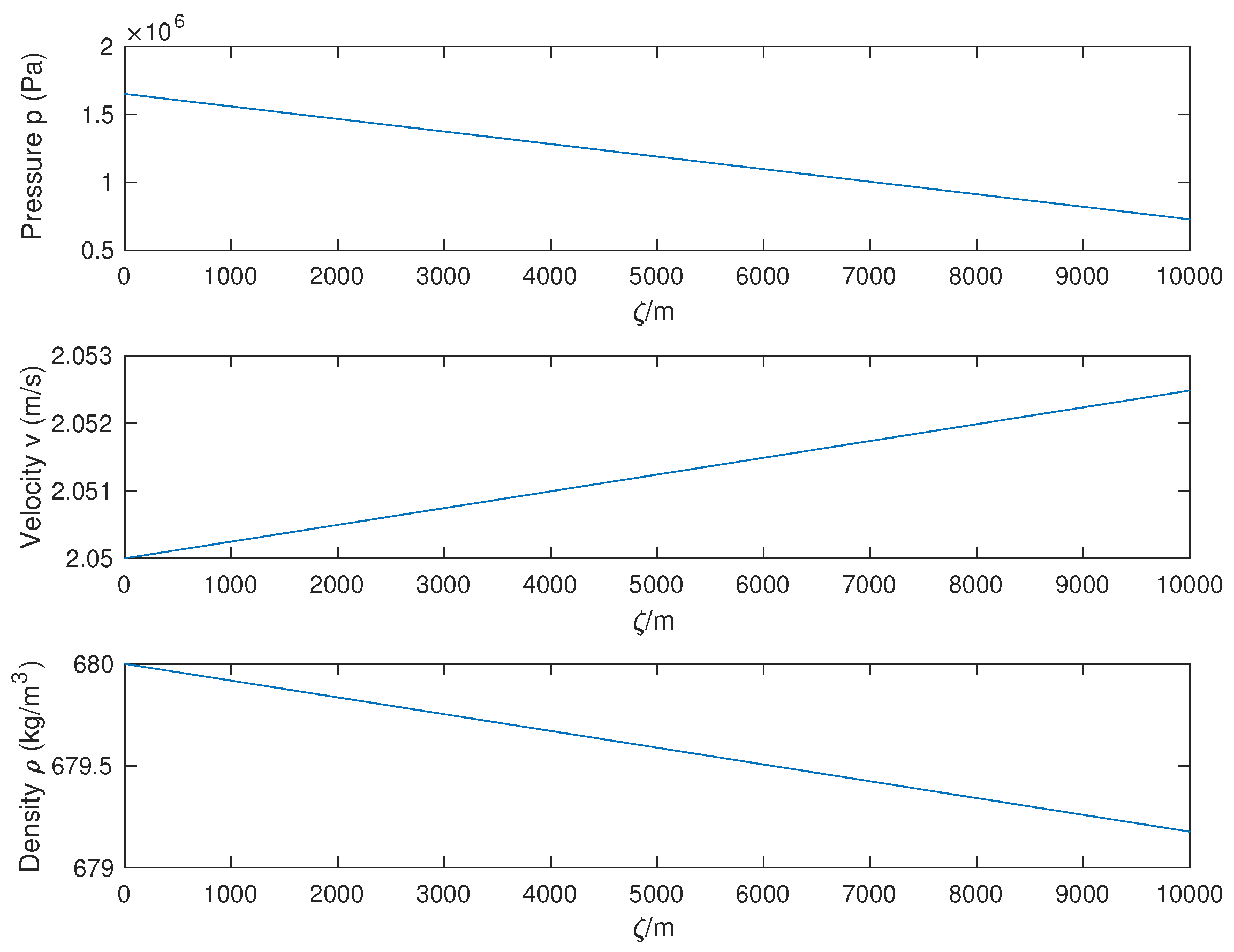
By using the pipeline parameters in Table 1 and assuming the incoming liquid flow with boundary conditions of v 0 = 2.05 m/s, p 0 = 1.68 × 10 6 Pa, and ρ 0 = 680 kg/m 3 , one can determine the steady states profiles as illustrated in Figure 2.
Then, a linearized water hammer system is obtained by applying the change of variables as Θ ¯ ( ζ , t ) = Θ ( ζ , t ) Θ s s ( ζ , t ) (where Θ : = v , p, or ρ ) and the proceeding Taylor series expansion as follows:
p ¯ t + v s s p ¯ ζ + v ¯ p s s ζ + a 2 ρ s s v ¯ ζ + p ¯ v s s ζ = 0
v ¯ t + p ¯ v s s a 2 ρ s s + v ¯ v s s ζ + v s s v ¯ ζ + 1 ρ s s p ¯ ζ + g sin α a 2 ρ s s + λ v s s 2 2 D a 2 ρ s s p ¯ + λ v ¯ v s s D = 0
with associated boundary conditions described as:
v ¯ ( 0 , t ) = u ( t ) , p ¯ ( L d , t ) = 0 , ρ ¯ ( L d , t ) = 0
In the above derivation, a two-state system (pressure and velocity) is obtained by consideration of p ¯ = ρ ¯ a 2 . For simplicity, a matrix form is further obtained as follows:
t p ¯ ( ζ , t ) v ¯ ( ζ , t ) + L N G L ζ p ¯ ( ζ , t ) v ¯ ( ζ , t ) + T R Q F p ¯ ( ζ , t ) v ¯ ( ζ , t ) = 0
where all notations are defined as follows:
L = v s s , R = p s s ζ , N = a 2 ρ s s , T = v s s ζ , G = 1 ρ s s Q = v s s a 2 ρ s s v s s ζ + g sin α a 2 ρ s s + λ v s s 2 2 D a 2 ρ s s , F = v s s ζ + λ v s s D
As shown in Figure 2, the spatial derivative of steady velocity v s s ζ is close to zero (spatial variation across the space is small enough), so T can be treated as zero. Compared to the large numerical value of N = a 2 ρ s s , the other terms L and R can be approximately neglected as zero. Along this line, a simplified matrix form is yielded and an output operator C is formulated to complete the infinite-dimensional water hammer system representation:
t p ¯ ( ζ , t ) v ¯ ( ζ , t ) = A p ¯ ( ζ , t ) v ¯ ( ζ , t )
y ( t ) = C p ¯ ( ζ , t ) v ¯ ( ζ , t )
with D ( A ) = { x = ϕ 1 ( ζ ) , ϕ 2 ( ζ ) L 2 ( 0 , L d ) , ϕ 1 ( L d ) = 0 , ϕ 2 ( 0 ) = u ( t ) , ϕ 1 ( ζ ) , and ϕ 2 ( ζ ) being absolutely continuous (abs. con.)}, and continuous-time spatial operators are defined as:
A : = 0 N ζ Q + G ζ F
C : = 0 L d δ ( ζ ) ( · ) d ζ 0 0 0 L d δ ( ζ L d ) ( · ) d ζ
where δ ( ζ ) and δ ( ζ L d ) are Dirac delta functions, while the corresponding notations are simplified as below:
N = a 2 ρ s s , G = 1 ρ s s
Q = g sin α a 2 ρ s s + λ v s s 2 2 D a 2 ρ s s , F = λ v s s D
Remark 2.
As for negative velocity in Equations (27)–(29), the same linearization steps (30)–(36) can be replicated, and the linear water hammer model structure is identical to Equations (37) and (39) with the same notations of N and G given in Equation (41), but different expressions of Q and F, described as follows:
Q = g sin α a 2 ρ s s λ v s s 2 2 D a 2 ρ s s , F = λ v s s D
Up to now, a linearized infinite-dimensional continuous-time water hammer system with boundary control has been derived. To ensure the modelling consistency with the stochastic discrete model (12) and (13), the boundary control water hammer system is converted into an abstract in-domain control model in the next section.

4.3. In-Domain Control Problem

In order to realize Kalman filter design, an in-domain control model is obtained from the boundary control model (37)–(40). In order to construct the spatial distribution function B that achieves the boundary to in-domain model transformation, the following theorem is utilized [3].
Theorem 1.
A boundary control PDE system ( z ˙ = L ¯ z with boundary input operator G ¯ z = u ) can be converted to an in-domain control PDE system ( z ˙ = A ¯ z + B ¯ u with boundary condition G ¯ z = 0 ) by solving the following inner product operator equation:
L ¯ z , ψ = z , A ¯ * ψ + G ¯ z , B ¯ * ψ
where z X , u U , Z = H 1 ( 0 , ) , L ¯ L ( Z , X ) , G ¯ L ( Z , U ) , Z X , with X, Z and U are the state space, solution space and input space. Additionally, z D ( L ¯ ) , ψ D ( A ¯ * ) , X 1 = Ker G ¯ = H 0 1 ( 0 , ) , and A ¯ = L ¯ | X 1 , where X, Z and X 1 are infinite-dimensional Hilbert spaces, (see pp. 317–322, in [3]).
By using the above Theorem 1, one can convert the boundary control model (37)–(40) into the in-domain control model as follows:
t p ¯ ( ζ , t ) v ¯ ( ζ , t ) = A 1 p ¯ ( ζ , t ) v ¯ ( ζ , t ) + B u ( t )
y ( t ) = C p ¯ ( ζ , t ) v ¯ ( ζ , t )
where:
A 1 : = 0 N ζ Q + G ζ F , B = N δ ζ N G δ ζ
C : = 0 L d δ ( ζ ) ( · ) d ζ 0 0 0 L d δ ( ζ L d ) ( · ) d ζ
with D ( A 1 ) = { x = ϕ 1 ( ζ ) , ϕ 2 ( ζ ) L 2 ( 0 , L d ) , ϕ 1 ( L d ) = 0 , ϕ 2 ( 0 ) = 0 , ϕ 1 ( ζ ) , and ϕ 2 ( ζ ) being abs. con.} and δ ζ defined as a Dirac delta function.
Proof. 
For the sake of simplicity, the following change of variables are applied:
x ¯ ( ζ , t ) y ¯ ( ζ , t ) = 1 2 1 2 N G 1 2 1 2 N G p ¯ ( ζ , t ) v ¯ ( ζ , t )
Then, substituting Equation (49) into Equation (37) yields the following:
t x ¯ ( ζ , t ) y ¯ ( ζ , t ) = L ¯ x ¯ ( ζ , t ) y ¯ ( ζ , t )
with state evolution operator L ¯ described as:
L ¯ = N G ζ + Δ Π Δ N G ζ Π
where Δ = N G Q F 2 , Π = N G Q + F 2 and the corresponding domain given as D ( L ¯ ) = { x = ϕ 1 ( ζ ) , ϕ 2 ( ζ ) L 2 ( 0 , L d ) , ϕ 1 ( L d ) + ϕ 2 ( L d ) = 0 , ϕ 1 ( 0 ) + ϕ 2 ( 0 ) = N G u ( t ) , , ϕ 1 ( ζ ) , and ϕ 2 ( ζ ) being abs. con. } .
Then, to convert the boundary control model into the associated in-domain control counterpart with respect to new states [ x ¯ ( ζ , t ) , y ¯ ( ζ , t ) ] , we consider the following system:
t x ¯ ( ζ , t ) y ¯ ( ζ , t ) = A ¯ x ¯ ( ζ , t ) y ¯ ( ζ , t ) + B ¯ u ( t )
It is apparent that A ¯ has the same expression as L ¯ , but with a different domain defined as D ( A ¯ ) = { x = ϕ 1 ( ζ ) , ϕ 2 ( ζ ) L 2 ( 0 , L d ) , ϕ 1 ( L d ) + ϕ 2 ( L d ) = 0 , ϕ 1 ( 0 ) ϕ 2 ( 0 ) = 0 , , ϕ 1 ( ζ ) , and ϕ 2 ( ζ ) being abs. con. } .
By solving the inner product equation A ϕ 1 , ϕ 2 = ϕ 1 , A * ϕ 2 , one can readily get:
A ¯ * = N G ζ + Δ Δ Π N G ζ Π
with the associated domain defined as D ( A ¯ * ) = { x = ϕ 1 ( ζ ) , ϕ 2 ( ζ ) L 2 ( 0 , L d ) , ϕ 1 ( L d ) + ϕ 2 ( L d ) = 0 , ϕ 1 ( 0 ) ϕ 2 ( 0 ) = 0 . . ϕ 1 ( ζ ) and ϕ 2 ( ζ ) are abs. con. } .
Along this line, one can utilize Theorem 1 to yield the following expression:
L ¯ z 1 z 2 , ψ 1 ψ 2 = z 1 z 2 , A ¯ * ψ 1 ψ 2 + G ¯ z 1 z 2 , B ¯ * ψ 1 ψ 2
where the boundary control operator is defined as: G ¯ = [ 0 L d δ ( ζ ) ( · ) d ζ , 0 L d δ ( ζ ) ( · ) d ζ ] , [ z 1 , z 2 ] D ( L ¯ ) , and [ ψ 1 , ψ 2 ] D ( A ¯ * ) . Through simple manipulation, one can solve for B ¯ as: B ¯ = [ N δ ( ζ ) , 0 ] T . □
Finally, one can attain the control action operator B corresponding to the original states [ v ¯ ( ζ , t ) , p ¯ ( ζ , t ) ] by using inverse linear transformation in Equation (49) as follows:
B = N δ ζ N G δ ζ
Up to now, a standard linearized continuous-time infinite-dimensional water hammer system (45)–(48) with in-domain control has been obtained.

4.4. Model Discretization

In order to realize a corresponding discrete-time pipeline system in the form of Equations (9) and (10) with the notations given in Equation (11), the resolvent operator needs to be determined beforehand for the considered infinite-dimensional pipeline system representation, as an important link to connect continuous- and discrete-time models. Since the resolvent operator is only related to the A 1 operator in Equation (45), one can directly apply Laplace transformation to Equation (45) without consideration of the input injection operator B as follows:
p ¯ ( ζ , s ) v ¯ ( ζ , s ) = e M ζ p ¯ ( 0 , s ) v ¯ ( 0 , s ) + 0 ζ e M ( ζ η ) A 0 1 p ¯ ( η , 0 ) v ¯ ( η , 0 ) d η
where:
A 0 = 0 N G 0 , B 0 = s 0 Q F + s , M = A 0 1 B 0
Furthermore, one can define e M ζ in the following form:
e M ζ = M 11 ( ζ , s ) M 12 ( ζ , s ) M 21 ( ζ , s ) M 22 ( ζ , s )
It is simple to solve for e M ζ in the following analytic expression:
M 11 ( ζ , s ) = [ c o s h ( ϑ ζ ) ϱ ϑ s i n h ( ϑ ζ ) ] e ϱ ζ M 12 ( ζ , s ) = 2 ( F + s ) 2 ϑ G s i n h ( ϑ ζ ) e ϱ ζ M 21 ( ζ , s ) = s ϑ N s i n h ( ϑ ζ ) e ϱ ζ M 22 ( ζ , s ) = [ c o s h ( ϑ ζ ) + ϱ ϑ s i n h ( ϑ ζ ) ] e ϱ ζ
where ϑ and ϱ are denoted as follows:
ϑ = N ( N Q 2 + 4 G s 2 + 4 F G s ) 2 N G ϱ = Q 2 G
Finally, the distributed parameter pipeline system can be manipulated in the following compact form:
p ¯ ( ζ , s ) v ¯ ( ζ , s ) = M 11 ( ζ , s ) M 12 ( ζ , s ) M 21 ( ζ , s ) M 22 ( ζ , s ) p ¯ ( 0 , s ) v ¯ ( 0 , s ) + 0 ζ M 11 ( ζ η , s ) M 12 ( ζ η , s ) M 21 ( ζ η , s ) M 22 ( ζ η , s ) A 0 1 p ¯ ( η , 0 ) v ¯ ( η , 0 ) d η
By substituting boundary conditions p ¯ ( L d , s ) = 0 and v ¯ ( 0 , s ) = 0 , one can solve for the expression of p ¯ ( 0 , s ) such that the resolvent operators are generated as follows:
p ¯ ( ζ , s ) v ¯ ( ζ , s ) = R 11 ( s , M ) R 12 ( s , M ) R 21 ( s , M ) R 22 ( s , M ) p ¯ ( η , 0 ) v ¯ ( η , 0 )
where:
R 11 ( s , M ) ( · ) = M 11 ( ζ , s ) M 11 ( L d , s ) N 0 L d M 12 ( L d η , s ) ( · ) d η + 1 N 0 ζ M 12 ( ζ η , s ) ( · ) d η R 12 ( s , M ) ( · ) = M 11 ( ζ , s ) M 11 ( L d , s ) G 0 L d M 11 ( L d η , s ) ( · ) d η + 1 G 0 ζ M 11 ( ζ η , s ) ( · ) d η R 21 ( s , M ) ( · ) = M 21 ( ζ , s ) M 11 ( L d , s ) N 0 L d M 12 ( L d η , s ) ( · ) d η + 1 N 0 ζ M 22 ( ζ η , s ) ( · ) d η R 22 ( s , M ) ( · ) = M 21 ( ζ , s ) M 11 ( L d , s ) G 0 L d M 11 ( L d η , s ) ( · ) d η + 1 G 0 ζ M 21 ( ζ η , s ) ( · ) d η
with all notations given by Equations (59) and (60). Up to now, a linear infinite-dimensional discrete-time water hammer system has been derived. In the same manner as Equations (12) and (13), the corresponding stochastic linear infinite-dimensional discrete-time water hammer system can be yielded.

4.5. Simulation Results of the Water Hammer Equation

In this section, the developed discrete-time Kalman filter design procedures (14)–(20) are applied to the resulting stochastic linear infinite-dimensional discrete-time water hammer system. In addition, the temporal and spatial intervals are 8 s and 500 m. As for the plant and measurement noises, we take w k N ( 0 , Q k ) , v k N ( 0 , R k ) , E [ w k w j T ] = Q k δ k , j , E [ v k v j T ] = R k δ k , j , E [ v k w j T ] = 0 , with R k = 0 . 01 and Q k = 0.001 . In particular, the initial conditions and the control action are given as follows:
p ¯ 0 ( ζ ) = 0 . 1 d p s s d ζ ( L d ζ ) , v ¯ 0 ( ζ ) = 10 d v s s d ζ ζ
u ( t ) = 0.0021 sin ( 0.0021 π t ) + 0.0021
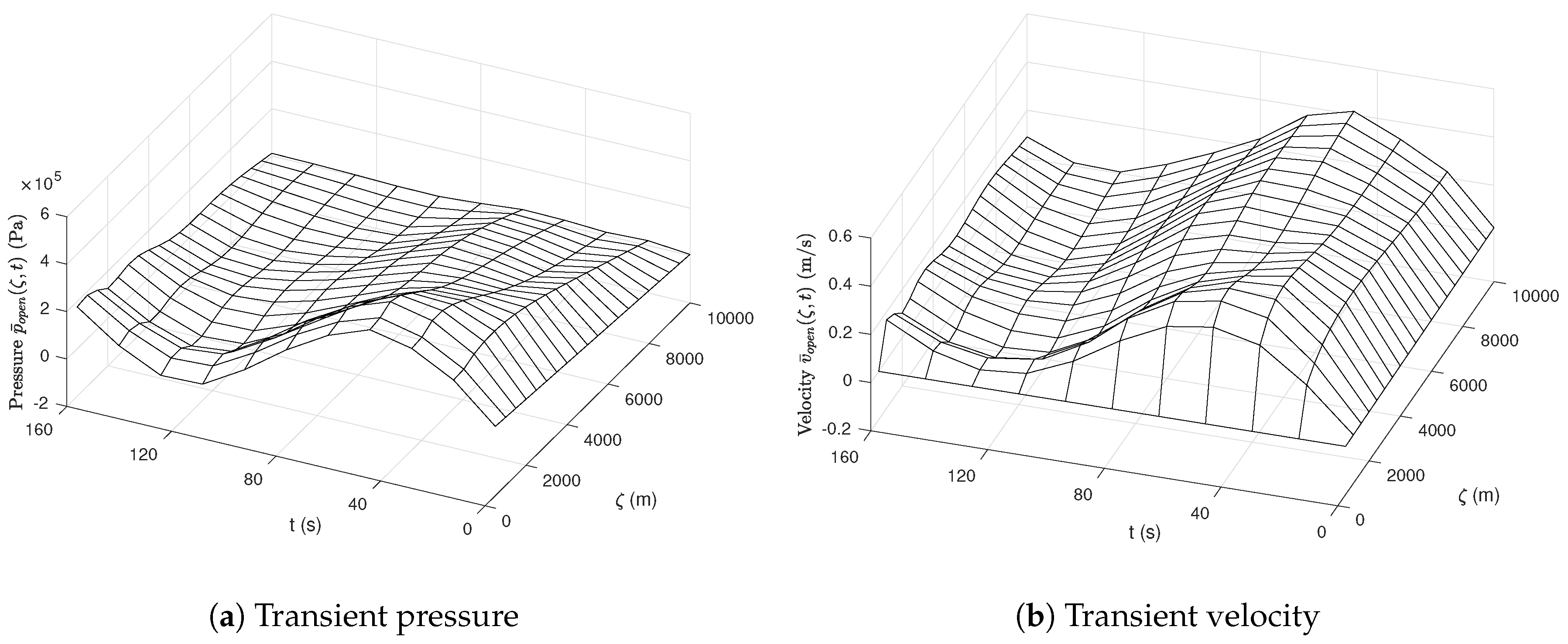
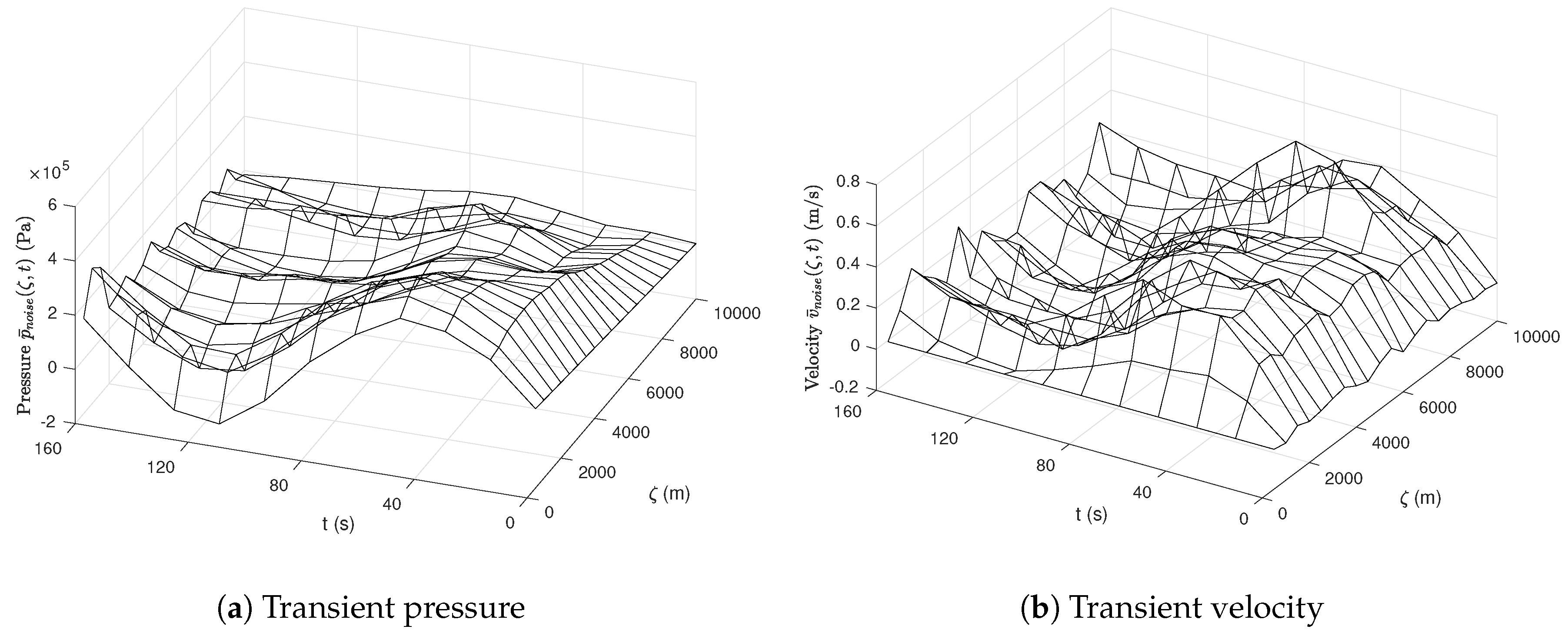
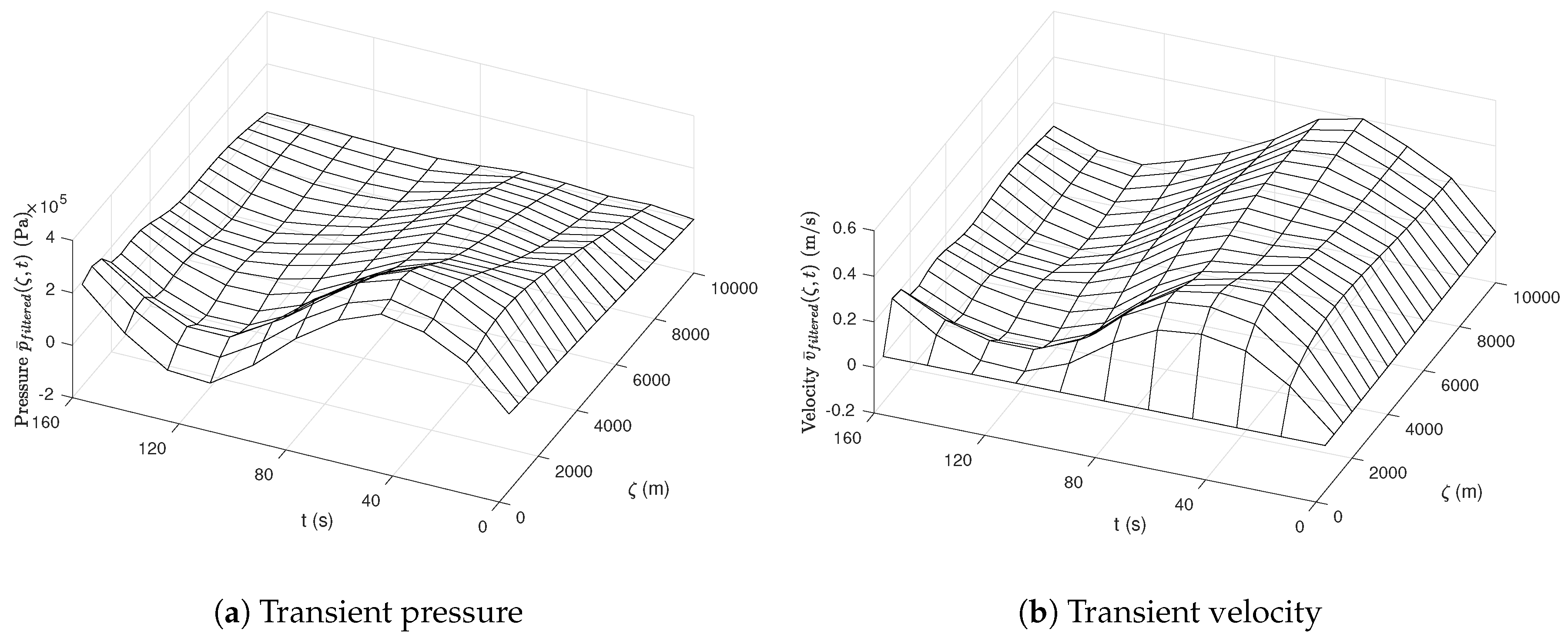
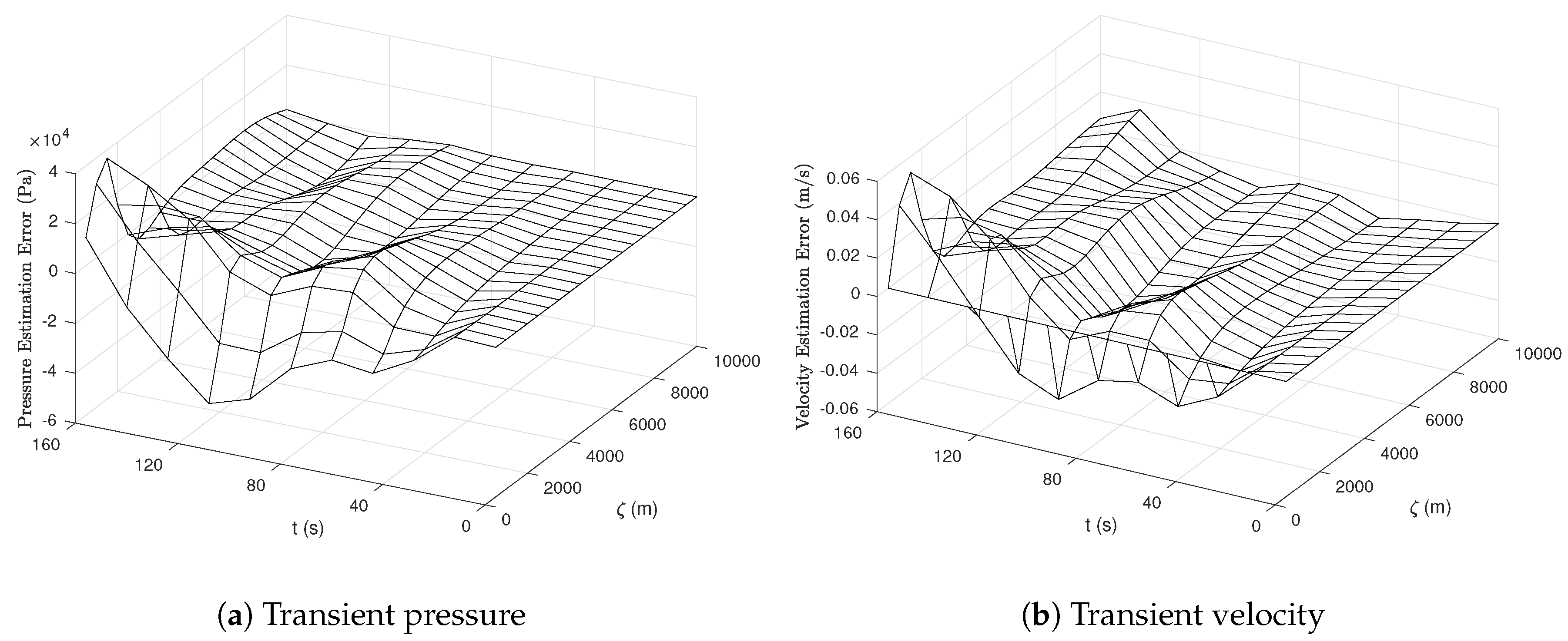
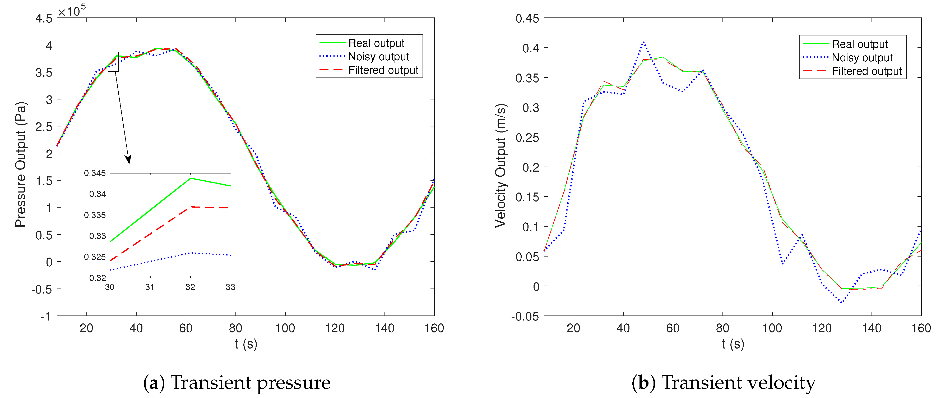
Based on that, the stochastic model dynamic and the associated filtering performance are simulated, as shown in Figure 3, Figure 4, Figure 5, Figure 6 and Figure 7. The transient velocity and pressure are considered here, and it is apparent that the profiles roughly follow the periodic wave trend, induced by the input action, but they are quite noisy in Figure 4. After applying the developed discrete Kalman filter, one can easily see that the noise has been filtered out, and the original dynamic evolution is revealed, which verifies the effectiveness of the proposed discrete Kalman filter, as shown in Figure 3 and Figure 5. As shown in Figure 6, the estimation errors are relatively small compared to the real state magnitudes. From the output filtering perspective in Figure 7, one can readily observe that the noisy pressure and velocity at boundary ends are quite noisy, as shown in the blue dashed lines, and the proposed Kalman filter can smooth out the noisy output profiles and make the filtered output converge to real output profiles, as shown in red dashed lines and green solid lines. In addition, the overall simulation time is 160 s. In this manuscript, the simulations are carried out based on MATLAB R2017a on a MacBook Pro 2017 (processor: 3.1 GHz, IntelCore i5’ memory: 8 GB 2133 MHz LPDDR3; operation system: Mac OS Sierra 10.12.06).
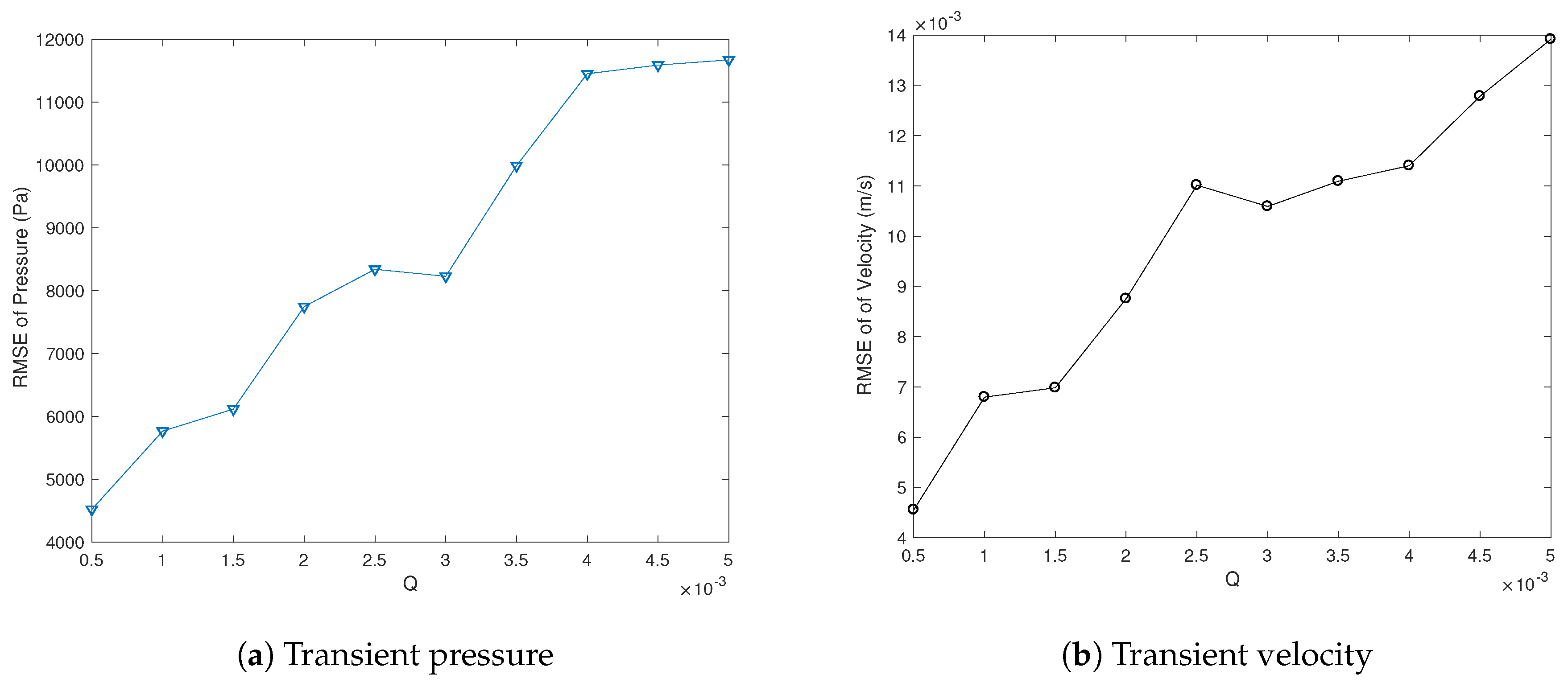
To account for the potential model mismatch, we consider the effect of process noises on output filtering performance. More specifically, we simulate Q k = [ 0.0005 : 0.0005 : 0.005 ] under the same measurement noise with a fixed covariance R k = 0.01 . To quantity the estimation accuracy, we calculate the root-mean-squared-error (RMSE) based on the real (noise-free) outputs. To account for the randomness of the generated noises, we simulate ten times and calculate the average value of RMSE. As shown in Figure 8, we can observe that the estimation RMSE increases with the process noise Q k increase. A proper selection of Q k is in the range of [0.0005,0.0015] where the RMSE of pressure and velocity is relatively small.

5. Wave System

5.1. Model Description

In this section, we consider a damped wave equation varying within a 1D spatial domain z with a unit length, boundary control, and observation as follows:
2 t 2 w z , t = 1 ρ ( z ) z T ( z ) z w z , t
T ( z ) z w 1 , t + κ t w 1 , t = 0
u ( t ) = T ( z ) z w 0 , t
y ( t ) = t w 0 , t
where κ , ρ , and T represent the model parameter, mass density, and Young’s modulus. For the sake of simplicity, we assume these parameters are constants.
To obtain a state-space model, an extended state is introduced as follows:
x z , t = x 1 z , t x 2 z , t = ρ w z , t t w z , t z
where x X = L 2 ( [ 0 , 1 ] ; R 2 ) , and the updated plant is described as the following boundary control model:
t x ( z , t ) = L x ( z , t )
G x ( z , t ) = u ( t )
with the model evolution operators defined as below:
L ( · ) : = 0 T 1 ρ 0 z ·
G ( · ) : = 0 T δ ( z ) ( · )
where D ( L ) : = { x = [ x 1 , x 2 ] T X : H x X 1 ( [ 0 , 1 ] ; R 2 ) , κ ρ x 1 ( 1 ) + T x 2 ( 1 ) = 0 , x 2 ( 0 ) = u } , and δ ( z ) is the Dirac delta function applied at z = 0 . The eigenvalues are given by λ k = 1 2 T ρ l o g ( ρ T κ ρ T + κ ) + T ρ k π i for k Z , and we further assume κ < ρ T to adopt a stable wave system for the ensuing model analysis and Kalman filter design; see [79].
Let us revisit Theorem 1 and generate the following abstract in-domain state space model:
t x ( z , t ) = A x ( z , t ) + B u ( t )
y ( t ) = C x ( z , t )
where:
A ( · ) : = 0 T 1 ρ 0 z ·
B ( · ) : = δ ( z ) 0 ( · )
C ( · ) : = 1 ρ 0 1 δ ( z ) ( · ) d z 0
where D ( A ) : = { x = [ x 1 , x 2 ] T X : H x X 1 ( [ 0 , 1 ] ; R 2 ) , κ ρ x 1 ( 1 ) + T x 2 ( 1 ) = 0 , x 2 ( 0 ) = 0 } . In addition, the feedthrough operator from the input to the output D is zero.
Proof. 
It is apparent to show that A has the same expression as L , but a different domain as: D ( A ) : = { x = [ x 1 , x 2 ] T X : H x X 1 ( [ 0 , 1 ] ; R 2 ) , κ ρ x 1 ( 1 ) + T x 2 ( 1 ) = 0 , T x 2 ( 0 ) = 0 } . Based on A ϕ , ψ = ϕ , A * ψ , one can readily obtain:
A * ( · ) : = 0 1 ρ T 0 z ·
with the associated domain as: D ( A * ) : = { ψ = [ ψ 1 , ψ 2 ] T X : H ψ X 1 ( [ 0 , 1 ] ; R 2 ) , κ ψ 1 ( 1 ) ψ 2 ( 1 ) = 0 , ψ 2 ( 0 ) = 0 } . By using the inner product formula (44), one can eventually solve for B ( · ) : = δ ( z ) 0 T ( · ) . □

5.2. Model Discretization

As a key of the realization of discrete operators by using the Cayley–Tustin discretization method, we apply the Laplace transform to the plant (74) as follows:
s x ( z , s ) x ( z , 0 ) = 0 T 1 ρ 0 z x ( z , s )
After simple manipulation, this leads to:
z x ( z , s ) = 0 ρ s s T 0 x ( z , s ) 0 ρ 1 T 0 x ( z , 0 ) = A 0 x ( z , s ) B 0 x ( z , 0 )
where:
A 0 = 0 ρ s s T 0 , B 0 = 0 ρ 1 T 0
Then, we have the following solution by simple integration:
x ( z , s ) = e A 0 z x ( 0 , s ) 0 z e A 0 ( z η ) B 0 x ( z , 0 ) d η
where:
e A 0 z = cosh ( ρ T s z ) ρ T sinh ( ρ T s z ) 1 ρ T sinh ( ρ T s z ) cosh ( ρ T s z )
Using the boundary conditions of the model (74) and (75) given by D ( A ) , we can solve for x 2 ( 0 , s ) = 0 and:
x 1 ( z , s ) = ρ ρ T sinh ( ρ T s z ) + κ cosh ( ρ T s z ) 0 1 [ κ ρ T sinh ( ρ T s ( 1 η ) ) + cosh ( ρ T s ( 1 η ) ) ] x 1 ( η , 0 ) + [ ρ T sinh ( ρ T s ( 1 η ) ) + κ cosh ( ρ T s ( 1 η ) ) ] x 2 ( η , 0 ) d η
Plugging the above Equation (84) into Equation (83) leads to:
x ( z , s ) = ρ ρ T sinh ( ρ T s z ) + κ cosh ( ρ T s z ) cosh ( ρ T s z ) 1 ρ T sinh ( ρ T s z ) × 0 1 [ κ ρ T sinh ( ρ T s ( 1 η ) ) + cosh ( ρ T s ( 1 η ) ) ] ( · ) d η 0 1 [ ρ T sinh ( ρ T s ( 1 η ) ) + κ cosh ( ρ T s ( 1 η ) ) ] ( · ) d η T x ( η , 0 ) d η 0 z ρ T sinh ( ρ T s ( z η ) ) ρ cosh ( ρ T s ( z η ) ) 1 T cosh ( ρ T s ( z η ) ) ρ T sinh ( ρ T s ( z η ) ) x ( η , 0 ) d η
Then, the resolvent operator is given as below:
R ( z , s ) ( ) = ρ ρ T sinh ( ρ T s z ) + κ cosh ( ρ T s z ) cosh ( ρ T s z ) 1 ρ T sinh ( ρ T s z ) × 0 1 [ κ ρ T sinh ( ρ T s ( 1 η ) ) + cosh ( ρ T s ( 1 η ) ) ] ( · ) d η 0 1 [ ρ T sinh ( ρ T s ( 1 η ) ) + κ cosh ( ρ T s ( 1 η ) ) ] ( · ) d η T ( ) d η 0 z ρ T sinh ( ρ T s ( z η ) ) ρ cosh ( ρ T s ( z η ) ) 1 T cosh ( ρ T s ( z η ) ) ρ T sinh ( ρ T s ( z η ) ) ( ) d η
Finally, one can substitute Equation (87) into Equations (9)–(11) to generate the discrete wave equation system with associated discrete-time operators.

5.3. Simulation Results for the Wave Equation

In this section, we proceed with the discrete Kalman filter design for the resulting discretized wave equation system. More specifically, we take the numerical parameters as: ρ = 0.01 , T = 255 , κ = 0.85 . In addition, the temporal and spatial intervals are 1 s and 0.02 m. As for the plant and measurement noises, we adopt w k N ( 0 , Q k ) , v k N ( 0 , R k ) , E [ w k w j T ] = Q k δ k , j , E [ v k v j T ] = R k δ k , j , E [ v k w j T ] = 0 , with R k = 100 and Q k = 0.1 . Here, a relatively large value of R is set because of the amplified output induced by the small numerical value of ρ . The initial conditions and input signal are described as below:
x 0 ( z ) = 0.1 cos ( z π ) 0.1 sin ( 0.5 z π )
u ( t ) = 150 sin ( 0.1532 π t )
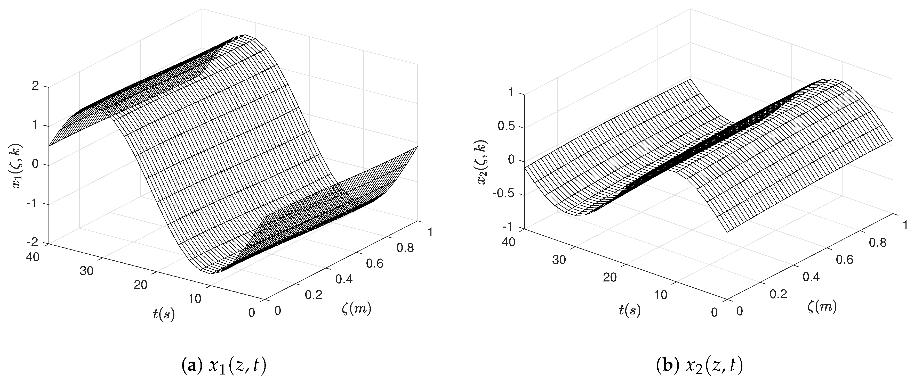
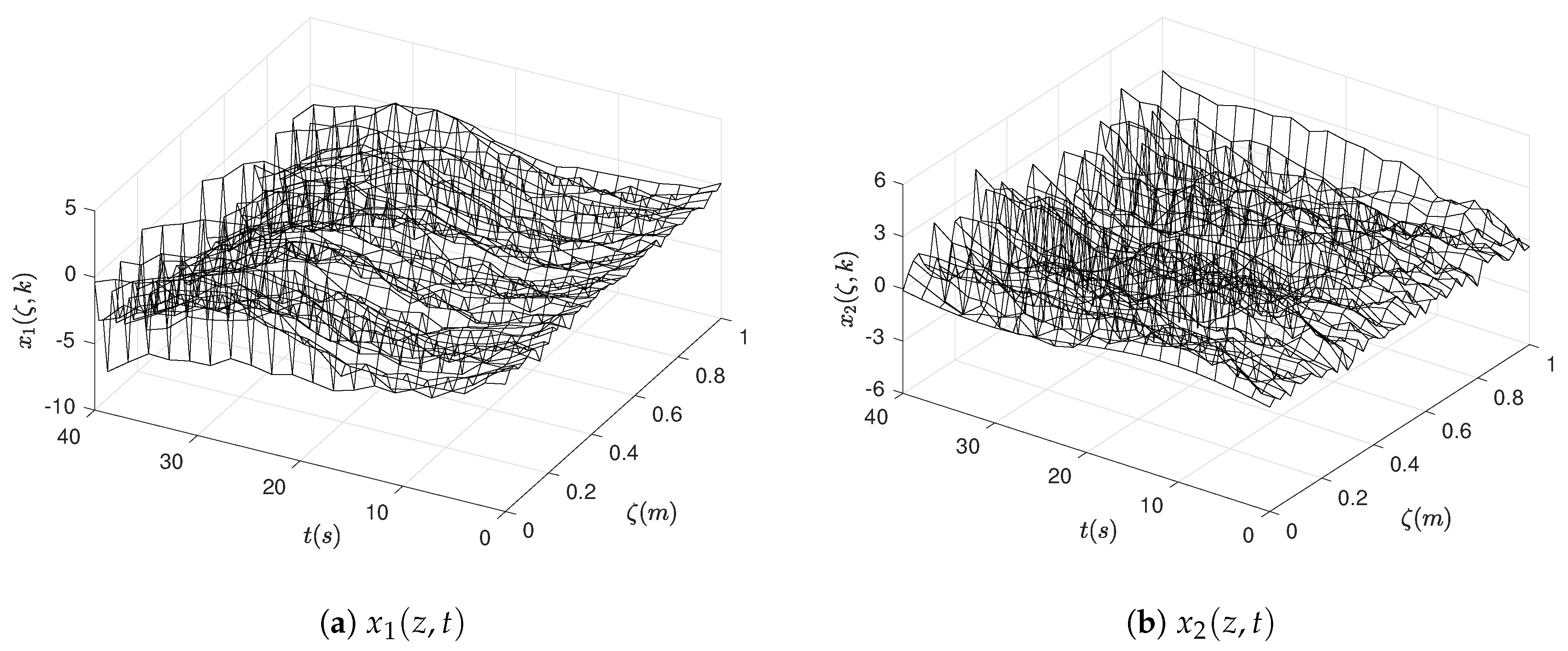
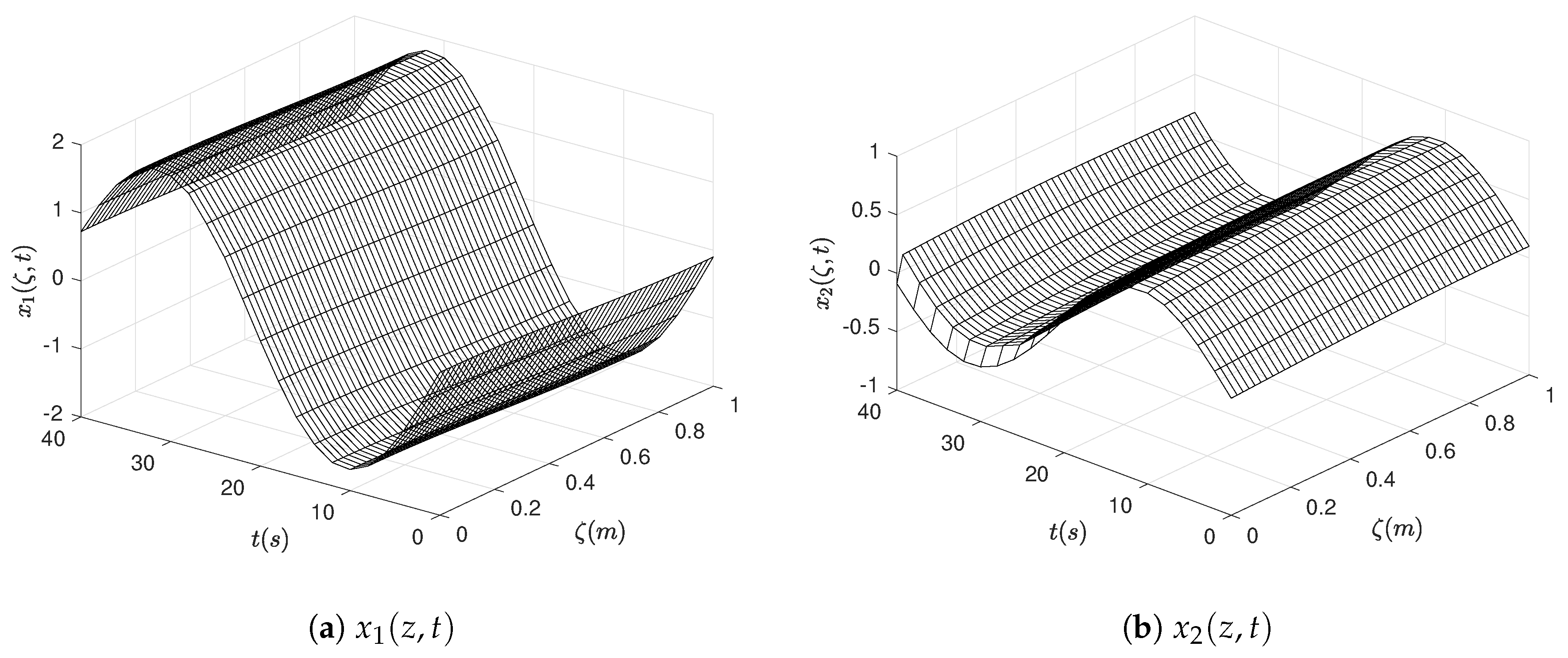
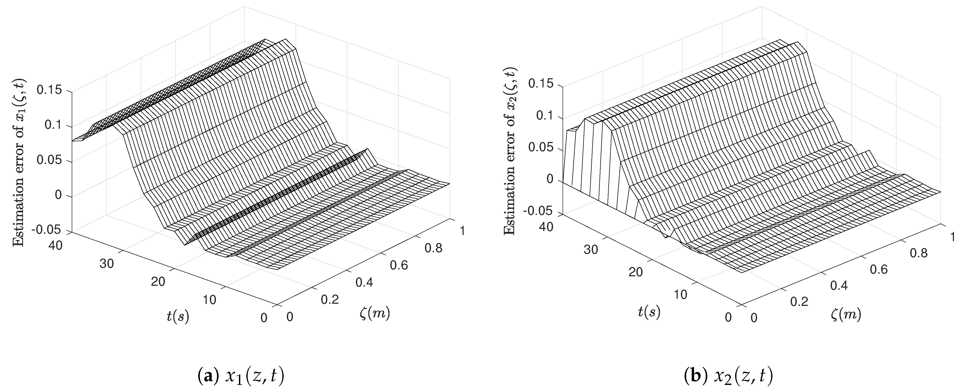
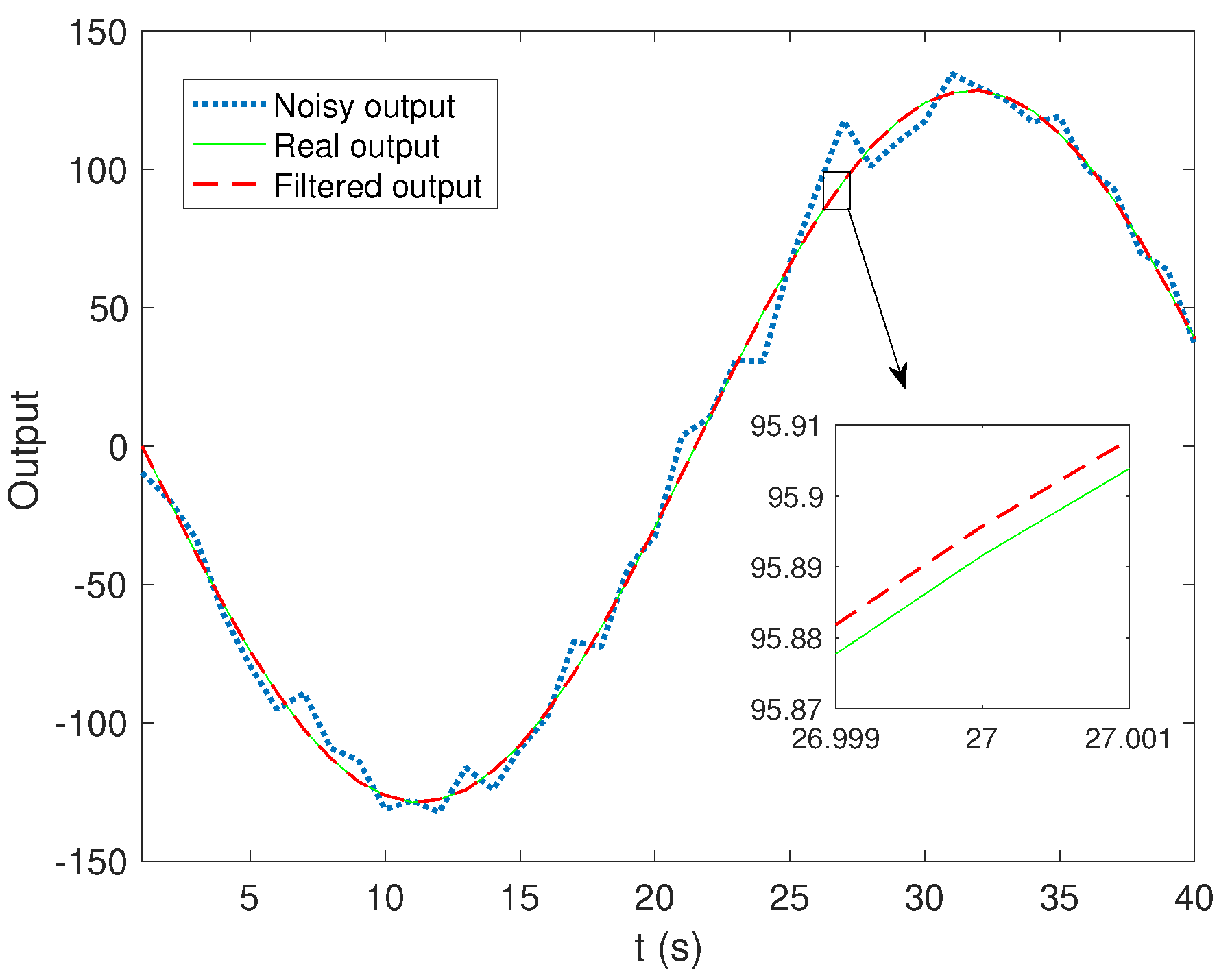
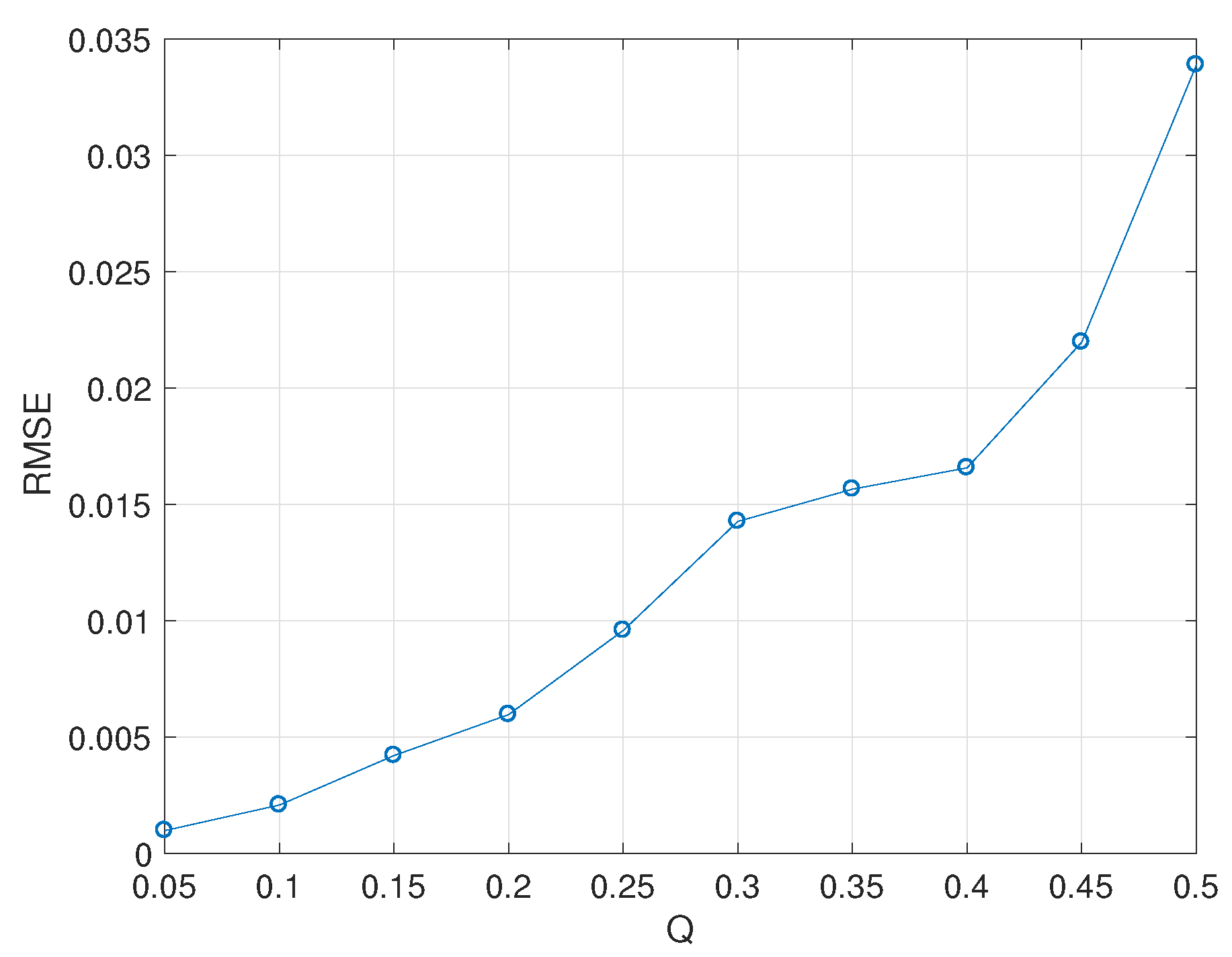
To elaborate the performance of the developed Kalman filter of the waver system, we present three simulation scenarios here, including: noise-free system, stochastic system, and filtered case. After 40 s of simulation, we emulate the noise-free state evolution, as shown in Figure 9. It is apparent that the two states x 1 ( z , t ) = ρ w ( z , t ) t and x 2 ( z , t ) = w ( z , t ) z follow sinusoidal wave propagation naturally. In the stochastic state profiles, the actual states are masked by noise, as in Figure 10. By using the discrete-time Kalman filter design, the noise has been filtered out from the stochastic system, leading to original state periodic propagation profiles, which can be seen in Figure 11. The effectiveness of the proposed Kalman filter can also be verified through the small state estimation errors in Figure 12 and output filtering performance in Figure 13 as well. As shown in Figure 13, we can readily see that the output is perfectly smoothed and reconstructed with the existence of process and measurement noises.
To consider the potential model mismatch, we simulate Q k = [ 0.05 : 0.05 : 0.5 ] under the same measurement noise with a fixed covariance R k = 100 and utilize RMSE to evaluate the estimation accuracy. As shown in Figure 14, it is apparent that with the process noise Q k increase, the RMSE of estimated output goes up rapidly, where each RMSE value is given based on the averaging of ten simulations. In this case, the estimation RMSE is small enough in the range of Q k = [ 0.05 : 0.05 : 0.5 ] , which can be applied in real-world applications.

6. Conclusions

In this work, we developed the discrete-time infinite-dimensional Kalman filter design for state estimation of linear distributed parameter systems with boundary controls and point observations. Using the Crank–Nicolson framework, a novel discrete-time distributed parameter system structure was derived and realized without spatial approximation or model order reduction. Based on that, a two-step infinite-dimensional discrete-time Kalman filter was developed with consideration of the spatial distribution of the process noise. To elaborate the filtering performance, two practical models with boundary control action applied were considered in this work, including a linear coupled hyperbolic PDE pipeline system (as a spectral system) and a 1D boundary damped wave model (as a non-spectral system). To account for the effect of process noise on estimation accuracy, we calculated the RMSE of estimated outputs under various simulation scenarios with different process noises and found that under the same measurement noise, with the process noise increase, the estimation RMSE went up. In the future, we will consider the constraint and stability issue and further extend the proposed design into nonlinear DPS models and applications.

Author Contributions

Conceptualization, J.X. and S.D.; Formal Analysis, J.X.; Methodology, J.X. and S.D.; Software, J.X.; Supervision, S.D.; Validation, J.X.; Visualization, J.X.; Writing, Original Draft, J.X.; Writing, Review and Editing, J.X. and S.D.

Funding

This research received no external funding.

Acknowledgments

We thank the anonymous reviewers for their constructive comments.

Conflicts of Interest

The authors declare no conflict of interest.

References

  1. Curtain, R.F.; Zwart, H. An Introduction to Infinite-Dimensional Linear Systems Theory; Springer-Verlag: New York, NY, USA, 1995. [Google Scholar]
  2. Ray, W.H. Advanced Process Control; McGraw-Hill: New York, NY, USA, 1981. [Google Scholar]
  3. Tucsnak, M.; Weiss, G. Observation and Control for Operator Semigroups; Springer Science & Business Media: Basel, Switzerland, 2009. [Google Scholar]
  4. Yu, T.K.; Seinfeld, J.H. Observability and optimal measurement location in linear distributed parameter systems. Int. J. Control 1973, 18, 785–799. [Google Scholar] [CrossRef]
  5. Temam, R. Infinite-Dimensional Dynamical Systems in Mechanics and Physics; Springer Science & Business Media: New York, NY, USA, 2012; Volume 68. [Google Scholar]
  6. Wu, R.B.; Tarn, T.J.; Li, C.W. Smooth controllability of infinite-dimensional quantum-mechanical systems. Phys. Rev. A 2006, 73, 012719. [Google Scholar] [CrossRef] [Green Version]
  7. Bastin, G.; Dochain, D. On-Line Estimation and Adaptive Control of Bioreactors; Elsevier Science Pub. B. V.: Amsterdam, The Netherlands, 1990. [Google Scholar]
  8. Dochain, D.; Babary, J.P.; Tali-Manaar, M.N. Modeling and Adaptive Control of Nonlinear Distributed Parameter Bioreactors via Orthogonal Collocation. Automatica 1992, 68, 873–883. [Google Scholar] [CrossRef]
  9. Renard, P.; Dochain, D.; Bastin, G.; Naveau, H.; Nyns, E.J. Adaptive Control of Anaerobic Digestion Processes: A Pilot-scale Application. Biotechnol. Bioeng. 1988, 31, 287–294. [Google Scholar] [CrossRef] [PubMed]
  10. Werner, J. Distributed-Parameter-Control of Human Body-Temperature. IFAC Proc. Vol. 1975, 8, 328–334. [Google Scholar] [CrossRef]
  11. Nagaiah, C.; Kunisch, K.; Plank, G. Numerical solution for optimal control of the reaction-diffusion equations in cardiac electrophysiology. Comput. Optim. Appl. 2011, 49, 149–178. [Google Scholar] [CrossRef]
  12. Chakrabarty, S.P.; Hanson, F.B. Optimal control of drug delivery to brain tumors for a distributed parameters model. In Proceedings of the American Control Conference, Portland, OR, USA, 8–10 June 2005; pp. 973–978. [Google Scholar]
  13. Schenk, O.; Manguoglu, M.; Sameh, A.; Christen, M.; Sathe, M. Parallel scalable PDE-constrained optimization: Antenna identification in hyperthermia cancer treatment planning. Comput. Sci.-Res. Dev. 2009, 23, 177–183. [Google Scholar] [CrossRef]
  14. Ray, W.H. Some recent applications of distributed parameter systems theory: A survey. Automatica 1978, 14, 281–287. [Google Scholar] [CrossRef]
  15. Luo, Z.H.; Guo, B.Z.; Morgül, Ö. Stability and Stabilization of Infinite Dimensional Systems with Applications; Springer Science & Business Media: London, UK, 2012. [Google Scholar]
  16. Tzafestas, S.G. Distributed Parameter Control Systems: Theory and Application; Elsevier: Amsterdam, The Netherlands, 2013; Volume 6. [Google Scholar]
  17. Kalman, R.E. A New Approach to Linear Filtering and Prediction Problems. Trans. ASME J. Basic Eng. 1960, 82, 35–45. [Google Scholar] [CrossRef] [Green Version]
  18. Welch, G.; Bishop, G. An Introduction to the Kalman Filter; University of North Carolina at Chapel Hill: Chapel Hill, NC, USA, 1995. [Google Scholar]
  19. Luenberger, D.G. Observing the state of a linear system. IEEE Trans. Mil. Electron. 1964, 8, 74–80. [Google Scholar] [CrossRef]
  20. Luenberger, D. Observers for multivariable systems. IEEE Trans. Autom. Control 1966, 11, 190–197. [Google Scholar] [CrossRef]
  21. Luenberger, D. An introduction to observers. IEEE Trans. Autom. Control 1971, 16, 596–602. [Google Scholar] [CrossRef]
  22. Dochain, D. State and parameter estimation in chemical and biochemical processes: A tutorial. J. Process Control 2003, 13, 801–818. [Google Scholar] [CrossRef]
  23. Dochain, D. State estimation in chemical and biochemical processes with uncertain kinetics. Ind. Eng. Chem. Res. 2002, 41, 4777. [Google Scholar]
  24. Bastin, G. On-Line Estimation and Adaptive Control of Bioreactors; Elsevier: Amsterdam, The Netherlands, 2013; Volume 1. [Google Scholar]
  25. Ali, J.M.; Hoang, N.H.; Hussain, M.A.; Dochain, D. Review and classification of recent observers applied in chemical process systems. Comput. Chem. Eng. 2015, 76, 27–41. [Google Scholar] [Green Version]
  26. Christofides, P.D. Control of nonlinear distributed process systems: Recent developments and challenges. AIChE J. 2001, 47, 514–518. [Google Scholar] [CrossRef]
  27. Dubljevic, S.; Mhaskar, P.; El-Farra, N.H.; Christofides, P.D. Predictive control of transport-reaction processes. Comput. Chem. Eng. 2005, 29, 2335–2345. [Google Scholar] [CrossRef]
  28. Christofides, P.D. Nonlinear and Robust Control of PDE Systems: Methods and Applications to Transport-Reaction Processes; Springer Science & Business Media: New York, NY, USA, 2012. [Google Scholar]
  29. Christofides, P.D.; Scattolini, R.; de la Pena, D.M.; Liu, J. Distributed model predictive control: A tutorial review and future research directions. Comput. Chem. Eng. 2013, 51, 21–41. [Google Scholar] [CrossRef]
  30. Lao, L.; Ellis, M.; Christofides, P.D. Economic model predictive control of parabolic PDE systems: Addressing state estimation and computational efficiency. J. Process Control 2014, 24, 448–462. [Google Scholar] [CrossRef]
  31. Zeitz, M. Observability canonical (phase-variable) form for non-linear time-variable systems. Int. J. Syst. Sci. 1984, 15, 949–958. [Google Scholar] [CrossRef]
  32. Zeitz, M. The extended Luenberger observer for nonlinear systems. Syst. Control Lett. 1987, 9, 149–156. [Google Scholar] [CrossRef]
  33. Mangold, M.; Lauschke, G.; Schaffner, J.; Zeitz, M.; Gilles, E.D. State and parameter estimation for adsorption columns by nonlinear distributed parameter state observers. J. Process Control 1994, 4, 163–172. [Google Scholar] [CrossRef]
  34. Zeitz, M. Nonlinear observers for chemical reactors. In Fortschrittberichte der VDI-Zeitschriften; VDI-Verlag: Duesseldorf, Germany, 1977. [Google Scholar]
  35. Bitzer, M.; Zeitz, M. Design of a nonlinear distributed parameter observer for a pressure swing adsorption plant. J. Process Control 2002, 12, 533–543. [Google Scholar] [CrossRef]
  36. Bück, A.; Peglow, M.; Tsotsas, E.; Mangold, M.; Kienle, A. Model-based measurement of particle size distributions in layering granulation processes. AIChE J. 2011, 57, 929–941. [Google Scholar] [CrossRef]
  37. Bakir, T.; Othman, S.; Fevotte, G.; Hammouri, H. Non linear observer for the reconstruction of crystal size distributions in polymorphic crystallization processes. IFAC Proc. Vol. 2006, 39, 667–672. [Google Scholar] [CrossRef]
  38. Pourkargar, D.B.; Armaou, A. Dynamic shaping of transport–reaction processes with a combined sliding mode controller and Luenberger-type dynamic observer design. Chem. Eng. Sci. 2015, 138, 673–684. [Google Scholar] [CrossRef]
  39. Krstic, M.; Kanellakopoulos, I.; Petar, V. Nonlinear Adaptive Control Design; Wiley: New York, NY, USA, 1995. [Google Scholar]
  40. Di Meglio, F.; Vazquez, R.; Krstic, M. Stabilization of a system of n + 1 coupled first-order hyperbolic linear PDEs with a single boundary input. IEEE Trans. Autom. Control 2013, 58, 3097–3111. [Google Scholar] [CrossRef]
  41. Krstic, M.; Fontaine, D.; Kokotovic, P.V.; Paduano, J.D. Useful nonlinearities and global stabilization of bifurcations in a model of jet engine surge and stall. IEEE Trans. Autom. Control 1998, 43, 1739–1745. [Google Scholar] [CrossRef]
  42. Aamo, O.M.; Krstic, M. Flow Control by Feedback: Stabilization and Mixing; Springer Science & Business Media: London, UK, 2013. [Google Scholar]
  43. Smyshlyaev, A.; Guo, B.Z.; Krstic, M. Arbitrary decay rate for Euler-Bernoulli beam by backstepping boundary feedback. IEEE Trans. Autom. Control 2009, 54, 1134–1140. [Google Scholar] [CrossRef]
  44. Meditch, J. On state estimation for distributed parameter systems. J. Frankl. Inst. 1970, 290, 49–59. [Google Scholar] [CrossRef]
  45. VandeWouwer, A.; Zeitz, M. State Estimation in Distributed Parameter Systems. In Encyclopedia of Life Support Systems (EOLSS): Control Systems, Robotics and Automation; EOLSS Publishers: London, UK, 2003. [Google Scholar]
  46. Hidayat, Z.; Babuska, R.; De Schutter, B.; Nunez, A. Observers for linear distributed-parameter systems: A survey. In Proceedings of the 2011 IEEE International Symposium on Robotic and Sensors Environments (ROSE), Montreal, QC, Canada, 17–18 September 2011; pp. 166–171. [Google Scholar]
  47. Yang, Y.; Dubljevic, S. Linear matrix inequalities (LMIs) observer and controller design synthesis for parabolic PDE. Eur. J. Control 2014, 20, 227–236. [Google Scholar] [CrossRef]
  48. Xu, X.; Huang, B.; Dubljevic, S. Optimal continuous-time state estimation for linear finite and infinite-dimensional chemical process systems with state constraints. J. Process Control 2015, 35, 127–142. [Google Scholar] [CrossRef]
  49. Kreuzinger, T.; Bitzer, M.; Marquardt, W. State estimation of a stratified storage tank. Control Eng. Pract. 2008, 16, 308–320. [Google Scholar] [CrossRef]
  50. John, T.; Guay, M.; Hariharan, N.; Naranayan, S. POD-based observer for estimation in Navier–Stokes flow. Comput. Chem. Eng. 2010, 34, 965–975. [Google Scholar] [CrossRef]
  51. Lehmann, O.; Luchtenburg, M.; Noack, B.R.; King, R.; Morzynski, M.; Tadmor, G. Wake stabilization using POD Galerkin models with interpolated modes. In Proceedings of the 44th IEEE Conference on Decision and Control, Seville, Spain, 15 December 2005; pp. 500–505. [Google Scholar]
  52. Van Waterschoot, T.; Leus, G. Distributed estimation of static fields in wireless sensor networks using the finite element method. In Proceedings of the 2012 IEEE International Conference on Acoustics, Speech and Signal Processing (ICASSP), Kyoto, Japan, 25–30 March 2012; pp. 2853–2856. [Google Scholar]
  53. Mechhoud, S.; Witrant, E.; Dugard, L.; Moreau, D. Estimation of heat source term and thermal diffusion in tokamak plasmas using a Kalman filtering method in the early lumping approach. IEEE Trans. Control Syst. Technol. 2014, 23, 449–463. [Google Scholar] [CrossRef]
  54. Smyshlyaev, A.; Krstic, M. Backstepping observers for a class of parabolic PDEs. Syst. Control Lett. 2005, 54, 613–625. [Google Scholar] [CrossRef]
  55. Jadachowski, L.; Meurer, T.; Kugi, A. Backstepping observers for linear PDEs on higher-dimensional spatial domains. Automatica 2015, 51, 85–97. [Google Scholar] [CrossRef]
  56. Nguyen, V.T.; Georges, D.; Besançon, G. State and parameter estimation in 1-D hyperbolic PDEs based on an adjoint method. Automatica 2016, 67, 185–191. [Google Scholar] [CrossRef] [Green Version]
  57. Xie, J.; Xu, Q.; Ni, D.; Dubljevic, S. Observer and filter design for linear transport-reaction systems. Eur. J. Control 2019. [Google Scholar] [CrossRef]
  58. Puust, R.; Kapelan, Z.; Savic, D.; Koppel, T. A review of methods for leakage management in pipe networks. Urban Water J. 2010, 7, 25–45. [Google Scholar] [CrossRef]
  59. Streeter, V.L.; Wylie, E.B.; Bedford, K.W. Fluid Mechanics. WCB; McGraw-Hill: New York, NY, USA, 1998. [Google Scholar]
  60. Ferrante, M.; Brunone, B.; Meniconi, S. Wavelets for the analysis of transient pressure signals for leak detection. J. Hydraul. Eng. 2007, 133, 1274–1282. [Google Scholar] [CrossRef]
  61. Wang, S.; Carroll, J.J. Leak detection for gas and liquid pipelines by transient modelling. In Proceedings of the International Oil & Gas Conference and Exhibition in China, Beijing, China, 5–7 December 2006; pp. 1–9. [Google Scholar]
  62. Colombo, A.F.; Lee, P.; Karney, B.W. A selective literature review of transient-based leak detection methods. J. Hydro-Environ. Res. 2009, 2, 212–227. [Google Scholar] [CrossRef]
  63. Vítkovskỳ, J.P.; Simpson, A.R.; Lambert, M.F. Leak detection and calibration using transients and genetic algorithms. J. Water Resour. Plan. Manag. 2000, 126, 262–265. [Google Scholar] [CrossRef]
  64. Krstic, M. Adaptive control of an anti-stable wave PDE. In Proceedings of the 2009 American Control Conference, St. Louis, MO, USA, 10–12 June 2009; pp. 1505–1510. [Google Scholar]
  65. Zhou, H.C.; Guo, B.Z.; Wu, Z.H. Output feedback stabilisation for a cascaded wave PDE-ODE system subject to boundary control matched disturbance. Int. J. Control 2016, 89, 2396–2405. [Google Scholar] [CrossRef]
  66. Feng, H.; Guo, B.Z. A new active disturbance rejection control to output feedback stabilization for a one-dimensional anti-stable wave equation with disturbance. IEEE Trans. Autom. Control 2016, 62, 3774–3787. [Google Scholar] [CrossRef]
  67. Rigatos, G.G. A Kalman Filtering approach of improved precision for fault diagnosis in distributed parameter systems. arXiv 2013, arXiv:1310.3358. [Google Scholar]
  68. Hairer, E.; Lubich, C.; Wanner, G. Geometric Numerical Integration: Structure-Preserving Algorithms for Ordinary Differential Equations; Springer Series in Computational Mathematics; Springer: Berlin, Germany, 2002; Volume 31. [Google Scholar]
  69. Havu, V.; Malinen, J. The Cayley transform as a time discretization scheme. Numer. Funct. Anal. Optim. 2007, 28, 825–851. [Google Scholar] [CrossRef]
  70. Staffans, O. Well-Posed Linear Systems; Cambridge University Press: Cambridge, UK, 2005; Volume 103. [Google Scholar]
  71. Malinen, J.; Staffans, O.; Weiss, G. When is a linear system conservative? Q. Appl. Math. 2006, 64, 61–91. [Google Scholar] [CrossRef] [Green Version]
  72. Xu, Q.; Dubljevic, S. Linear model predictive control for transport-reaction processes. AIChE J. 2017, 63, 2644–2659. [Google Scholar] [CrossRef]
  73. Havu, V.; Malinen, J. Laplace and Cayley transforms—An approximation point of view. In Proceedings of the 44th IEEE Conference on Decision and Control, 2005 and 2005 European Control Conference, CDC-ECC’05, Seville, Spain, 15 December 2005; pp. 5971–5976. [Google Scholar]
  74. Malinen, J. Tustin’s method for final state approximation of conservative dynamical systems. IFAC Proc. Vol. 2011, 44, 4564–4569. [Google Scholar] [CrossRef]
  75. Simon, D. Optimal State Estimation: Kalman, H, and Nonlinear Approaches; John Wiley & Sons: Hoboken, NJ, USA, 2006. [Google Scholar]
  76. Xie, J.; Xu, X.; Dubljevic, S. Long range pipeline leak detection and localization using discrete observer and support vector machine. AIChE J. 2019, 65, e16532. [Google Scholar] [CrossRef]
  77. Blažič, S.; Matko, D.; Geiger, G. Simple model of a multi-batch driven pipeline. Math. Comput. Simul. 2004, 64, 617–630. [Google Scholar] [CrossRef] [Green Version]
  78. Colebrook, C.F.; Blench, T.; Chatley, H.; Essex, E.; Finniecome, J.; Lacey, G.; Williamson, J.; Macdonald, G. Turbulent flow in pipes, with particular reference to the transition region between the smooth and rough pipe laws. J. Inst. Civ. Eng. 1939, 12, 393–422. [Google Scholar] [CrossRef]
  79. Dubljevic, S.; Humaloja, J.P. Model Predictive Control for Regular Linear Systems. arXiv 2018, arXiv:1808.10021. [Google Scholar]
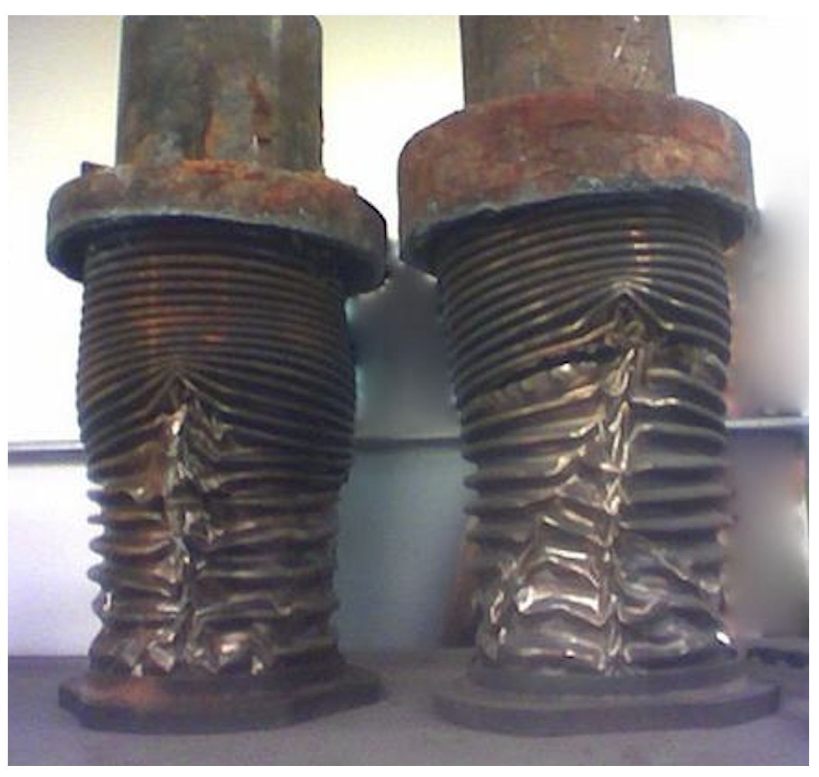
Figure 1. Effects of water hammer dynamics. (Cited from: https://en.wikipedia.org/wiki/Water_hammer).
Processes 07 00451 g001
Figure 2. Profiles of steady states given by Equations (30)–(32).
Processes 07 00451 g002
Figure 3. State evolution of the noise-free water hammer system.
Processes 07 00451 g003
Figure 4. State evolution of the noisy water hammer system.
Processes 07 00451 g004
Figure 5. State evolution of the filtered water hammer system.
Processes 07 00451 g005
Figure 6. State estimation errors of the filtered water hammer system.
Processes 07 00451 g006
Figure 7. Profiles of the filtered output of the water hammer system.
Processes 07 00451 g007
Figure 8. RMSE of estimated outputs of the water hammer system (R = 0.01).
Processes 07 00451 g008
Figure 9. State evolution of the noise-free wave system.
Processes 07 00451 g009
Figure 10. State evolution of the noisy wave system.
Processes 07 00451 g010
Figure 11. State evolution of the filtered wave system.
Processes 07 00451 g011
Figure 12. State estimation errors of the wave system.
Processes 07 00451 g012
Figure 13. Output filtering performance of the wave system.
Processes 07 00451 g013
Figure 14. RMSE of the estimated output of the wave system.
Processes 07 00451 g014
Table 1. Pipeline parameters.
TermNotationNumerical Value
Pipeline Length L d 10,000 m
Speed of Sounda1059 m/s
Friction Coefficient λ 0.0158
Gravity Accelerationg 9.81 m/s
Pipe DiameterD 0.2065 m
Inclination Angle α −0.00256