Abstract
As a damage element, high-speed fragments have a significant effect on the ammunition safety. The impact from the fragments are also one of the basic problems of ammunition safety tests. To clarify the reaction characteristics of combustion, explosion, detonation, and so on, when hypersonic fragments hit insensitive munitions, it is necessary to carry out corresponding research on the deceleration law of hypersonic fragment in the air. In this paper, a 30 mm caliber gun with large chamber, small caliber, and large aspect ratio is proposed to drive high-speed fragments. According to STANAG 4496 standard, a near-cylinder steel fragment with Brinell hardness HB ≤ 270 and mass of 18.6 g was designed. The test system was composed of zone interception velocity measurement, chamber pressure sensor, trajectory tracking system, high-speed camera, and other equipment were also established to obtain the pressure variations in the chamber, the velocity of the fragment, and its flight orientation. From the video taken by the high-speed camera and trajectory tracking system, the fragment and the projectile sabot achieve effective separation after the fragment travels out of the muzzle. As time goes on, the distance between the fragment and the projectile sabot gradually increases. The fragment is always in the front of the sabot and steadily flies to the target. The muzzle velocity of the fragment is controlled by adjusting the propellant charge, and the flight velocity in the air is measured by the zone interception velocity measuring device in the range of 5 Ma to 7 Ma. The theoretical models of fragment deceleration and the models of flight orientation are also established according to the experimental data. On this basis, F test and least square nonlinear regression fitting were used to analyze experimental data. Finally, the deceleration coefficient of quasi-cylindrical fragments between 5 Ma and 7 Ma stipulated in STANAG 4496 standard is 0.009312, and the average drag coefficient in air is 1.109.
1. Introduction
Testing the ammunition safety used on the weapon platform and fortifications is a challenging task. Even though the damage ability of the ammunition on the action target performs an important role, the self-security of the ammunition can avoid unnecessary damages to oneself [1,2,3,4]. Consequently, insensitive ammunition is always a key focus for most of researchers. The impact test of the fragment can be used for evaluating the safety performance of the ammunition [5,6,7,8,9,10,11,12,13,14]. However, the fragment depends on the kinetic energy to damage the target, thus the damage power is closely related to the fragment velocity, which also depends on the muzzle speed and the deceleration characteristic of the fragment [15].
Basic studies have been conducted to study velocity characteristics of the fragments in the launch process, experimentally and theoretically. Martijn et al. [16] studied the relations between motion trail of the projectile, launch energy, and impact energy by using TRAGCN software. Baker et al. [17] used the traditional drag formula to obtain the velocity–distance variation curve of the standard fragment with an initial velocity of 2530 m/s [18]. Their team [18] also carried out an impact test of standard fragment on a 120 mm forced bomb, but the deceleration law of the fragment is unclear due to lack of experimental data. Morrison et al. [19] investigated the drag coefficient of a spherical body and presented the calculation method of this drag coefficient. Singh et al. [20] proposed a generalized physical expression on the drag coefficient of a moving spherical particle in the fluid. The drag coefficient of a spherical body is 0.9 under the condition of hypersonic speed, which can be adopted to simulate the particle trajectories in high-speed dust flow. Goossens et al. [21] obtained the empirical correlation on the spherical body and Reynolds number by a linear regression of experimental data. Loth et al. [22] analyzed the drag coefficient of the spherical body in supersonic speed and hypersonic speed flows, then proposed a new empirical model on the drag coefficient, in which a general description on the drag coefficients is provided in wide ranges of Mach numbers, Knudsen numbers, and Reynolds numbers. Zhou et al. [23] established an image collecting system of different spherical particles to study the relationship of terminal velocity of the spherical particle and shapes, and the diameter, a prediction model was also presented to obtain the terminal velocity and drag coefficient. Hu et al. [24] showed a detailed introduction on the test procedure and evaluation criterion when the insensitive ammunition was impacted by a fragment. Ma [25] studied the distribution rule of the initial velocity of a natural fragment by a static detonation test. Ma et al. [26] analyzed the experimental data and obtained the empirical formula of flight drag coefficient of the fragment between Mach number 1 and Mach number 3. Yang et al. [27] obtained the flight rule of the prefab fragment driven by the detonation by a velocity-measuring system. Then, the average windward area, drag coefficient, and deceleration coefficient for a natural fragment with the mass of 1–4 g were all studied by Wang et al. [28]. Tan et al. [29] proposed a relationship between the drag coefficient of the fragments with different shapes and Mach numbers in a wind tunnel experiment. Wang et al. [30] also simulated the penetration process of the fragment with different structures and obtained the deceleration process of the flight velocity under different initial velocities. An average method on the regular icosahedron was adopted to investigate the drag coefficient of the air for non-spherical fragment in the flight process [31]. Based on STANAG 4496 [32], Hu et al. [33] carried out the optimizing calculation on the interior ballistic parameters of the launch system to obtain the optimal flight speed of the fragment for effectively damaging the target.
Significantly, the predictions of fragment size on the base of the energy balance law have been investigated recently. Grady et al. [34] quantitatively proposed a method to control the surface area that was generated in the separation process of the fragment via a balance of the surface and the local kinetic energy. Then, the energy dissipation phenomena in the separation process of the fragment were specially explained by Kipp et al. [35]. In addition, their team [35] presented the mathematical relationships of the size, separation time, and fracture strain of the fragment through adopting the Mott method. However, Glenn et al. [36] revised Grady’s model to obtain a more actual fragmentation process of the fragment. Englmant et al. [37] analyzed the fracture and separation of the materials in the formation process of the fragments based on the Mott distribution function for investigating the distribution characteristics of fragment size. Grady et al. [38] also presented the debris behaviors via the experiments where the high-speed fragment impacted a target. Sil’Vestrov [39] carried out studies on the distribution mechanism of the fragments during the separation and fragmentation of the projectile, and obtained the rules from irregular fragmentation to more uniform fragmentation based on the maximum impact velocity of the fragment. Cagle et al. [40] numerically studied fragmentation processes of the projectiles with different material properties that impacted the elastic targets. Myagkov [41] established the mathematical model for analyzing the separation behavior of aluminum projectile via adopting the method of smoothed particle hydrodynamics. Teng et al. [42] experimentally explained the behaviors when an equivalent fragment impacted on an equivalent ballistic missile warhead via establishing a flash X-ray measure system.
Therefore, most previous studies have investigated the fragmentation separation behaviors of the fragment and the damage degree of the target. The fragments were also generated by the explosion of the explosive or the gun launch, and the presented studies mostly focused on the spherical and square fragments. The flight characteristics on the fragment with a hypervelocity are still unclear due to lack of detailed data, especially experimental data. This work is focused on the deceleration characteristics of the fragment during the flying process, and we adopted the NATO standards to design the fragment with a combination shape of a cylinder and cone. In addition, a 30 mm caliber gun launch system is first designed to realize a launch process on a controllable fragment with a hypervelocity, and the corresponding test system is also established to obtain the deceleration characteristics of the moving fragment from the muzzle of the gun to the target. Based on the experimental data, the flight characteristics of the fragment under different working conditions are also analyzed by a deceleration model for obtaining a nonlinear fitting method. The results in this work can mainly provide the terminal velocity information when the fragment impacts the target that is different distances away from the gun muzzle for future studies of terminal effect. In other words, the muzzle velocity can be changed by adjusting the charge structure of the gun to realize the required impact velocity of the fragment.
2. Experimental System
2.1. Launching Device
To analyze the movement property of a fragment in high speed, a gun launch device than can drive the high-speed fragment via the combustion of the propellant is designed in this study, which adopts a small-caliber structure with a large chamber and length–diameter ratio. The caliber of the combustion chamber is 35 mm, the caliber of the barrel of the launch device is 30 mm, and the whole length of the barrel is 4.5 m. The detailed structure of the launch device is presented in Figure 1, including head tube, displacement regulating device, gun breech, anti-recoil buffer device, connection case, transition base, supporting base, and back tube. Both of the bumpers with recoil and advance are installed on the back tube according to the involution method of disc spring. The recoil can be absorbed by the anti-recoil buffer device in the launch process. This bumper device can reach the requirement of the maximum recoil of the launch device, 183 kN, which satisfies the high-speed ballistic condition in the experiment.

Figure 1.
Sub-caliber fragment loading device with ultra-high speed [33].
In the experiment, the barrel of the launch system is continually working under the condition of high-pressure propellant combustion gas. Thus, the barrel strength should be verified according to the maximum line deformation theory. The equation of the tangential stress of the inner surface of the barrel is expressed as:
The corresponding tangential stress of the outer surface is expressed as:
where is the inner radius, and and P are the outer radius and the chamber pressure, respectively.
According to the curve of the average pressure and displacement of the fragment under the condition of the maximum average pressure 400 MPa, the strength of the barrel is checked piecewise, and the permissible stress of the barrel is . The safety coefficients of the stress n are calculated by the following equation:
Table 1 presents the strength verification results of the tube. As it can be seen, the safety coefficients of the inner and outer surfaces for the distance that is 200 mm off the barrel end are larger than 1.49, which satisfies the strength requirement of the gun.

Table 1.
Strength verification of the tube [33].
According to the standard of STANAG 4496 “Impact test procedure of the projectile” from NATO, the experimental projectile is also designed. The projectile is composed of the sabot and projectile head that is surrounded by the sabot. The sabot can assure the movement safety and the flight stability of the projectile. However, the sabot is grooved to realize the effective separation of the sabot and the projectile head after the projectile flies out of the barrel. The sabot is pre-divided into four sections, and the pre-divided depth is related to the fragment velocity. Additionally, the projectile and the fragments are effectively separated by adjusting the propellant charge with a change of thrust. The diameter of the standard fragment made of the steel with a Brinell hardness of <270 is 14.3 ± 0.05 mm, and the length is 15.56 mm with a length–diameter ratio of 1. The head of the fragment is a circular cone with the angle of 160 ± 0.5° [15], and the density is 7.85 g/cm3. The mass of the whole fragment is 18.6 g. Figure 2 shows the structure and size of the experimental projectile.
Figure 2.
Size and shape of experimental projectile.
2.2. Test System in the Experiments
The deceleration test system on the fragment with ultra-high speed is composed of a pressure transducer, zone interception velocity measurement, ballistic tracking system, and high-speed camera. The chamber pressure variation with the time is obtained by the pressure transducer, and the fragment velocity is tested by the zone interception velocity measurement. Then, the flight process and orientation of the projectile can be traced by the ballistic tracking system and the separation processes of the fragments can be recorded by the high-speed camera. Figure 3 and Figure 4 show the experimental setup and the corresponding test devices. The zone interception velocity measurements are arranged in the position of 5 m, 10 m, 15 m, 20 m, 25 m, 30 m, 35 m, 40 m, 45 m, and 50 m away from the muzzle, respectively. The ballistic tracking system with the frame frequency of 10,000 f/s is placed on one side of the launch system and is vertical to the ballistic line of the launch system. In addition, a curtain with black and red coloring is loaded on the other side of the launch system, and the size of the curtain is 300 mm × 300 mm with the length of 50 m. The high-speed camera is set in the direction of the ballistic line of the launch system, and the frame frequency is 1000 f/s to obtain the separation process of the fragments.
Figure 3.
Layout diagram of the test system.

Figure 4.
Layout diagram of testing area.
3. Results on Ballistic Parameters
3.1. Chamber Pressure Characteristics of the Launch System
To obtain the effect of the propellant charge on the ballistic characteristics, the propellant charge is changed from 260 g to 346 g in the experiments. Table 2 presents the experimental results on the chamber pressure and fragment velocity under different propellent charges.
Table 2.
Relationship of propellant charge, chamber pressure, and velocity of the fragment.
As it can be seen from Table 2, the chamber pressure and the corresponding velocity of the fragment are all increasing with an increase in the propellant charge. However, when the fragment velocity increases from 1781.26 m/s to 2547.12 m/s, the chamber pressure of the launch system is always less than 400 MPa. This means the structure strength of the launch system can reach the design requirement during the experimental process.
3.2. Velocity Disributions of the Fragment
Table 3 presents the corresponding relationships of the position and time obtained by the zone interception velocity measurement under the abovementioned eight working conditions. According to Table 3, the average velocity of the fragment can be obtained by the distances of both targets and the corresponding time. Figure 5 shows the velocity–displacement relationship of the fragment between the midpoints of two targets. It can be seen that the fragment velocity has been larger than 2500 m/s in a position away from the muzzle of 7.5 m, which means that this launch system designed in this work can launch the fragment at ultra-high speed.
Table 3.
Position-Time relationship.
Figure 5.
Velocity–displacement relationship at the midpoint of two targets.
3.3. Flight Processes of the Fragment
Figure 6 shows separation processes and flight orientations of the fragment for No. 1 in Table 2. It can be seen that the fire flight occurs at 0 ms, presenting a successful ignition for the gun launch system. At 1 ms, the muzzle is surrounded by the flame, and the projectile flies off the muzzle flame. At 2 ms, the sabot and the fragment begin to separate from each other, initially. As time goes on, the fragment impacts the first target, and the flame occurs due to a crash effect. During the time range of 4 ms and 6 ms, the sabot and the fragment generates an obvious complete separation. The fragment flies in front of the four sabot sections, then is far away from the muzzle. The sabot sections also fall further behind the fragment. In sum, the fragment always flies in the front of the sabot for this quasi-cylindrical fragment structure. Then, the distance between the sabot and fragment increases with time. The spreading range of the sabot increases, but the fragment can still fly to the target steadily. The whole flight process satisfies the safety test requirement of the ammunition.
Figure 6.
Flight processes of fragment and projectile sabot.
4. Deceleration Characteristics of the Fragment Velocity
From the test safety, there is a certain distance between the gun system and impact target. This distance is 50 m in this work, which means that the initial velocity of the fragment and the impact velocity from terminal effect are very different. In the launch process of the gun, the muzzle initial velocity of the fragment can be obtained and determined and, the impact velocity on the target depends on the drag coefficient. Consequently, the process of obtaining the drag coefficient of the fragment is very important. In addition, based on this gun launch system, the path of the fragment must be considered, which determines whether the required terminal effect can succeed. In this section, the drag coefficients for the flight process of the fragment under long distances are also calculated.
4.1. Fundamental Theory of Deceleration Rule
As the fragment velocity is high and the mass is low, the gravity effect and the crosswise effect from the air friction in the flight process are ignored. Assuming that the fragment acts along the one-dimensional direction, the movement equation of high-velocity fragment is described as:
where m, ρ, and S are the fragment mass, air density, and the windward area of the fragment, respectively. For a non-spherical fragment, the windward area is always changing. In addition, v is the flight velocity of the fragment, and cx is the drag coefficient of the air.
The initial movement condition of the fragment is and . x is the flight displacement of the fragment and is the initial muzzle velocity. Then, Equation (4) is integrated in the time range, and the flight velocity is obtained as follows:
where , and . Additionally, the relationship between the fragment velocity v and flight displacement x can be expressed as:
where k is the deceleration coefficient of the fragment, which is related to the air drag coefficient, the fragment mass, and the windward side. Due to the influences of the experimental condition and random factor, the deceleration coefficient tested by the experiment cannot reflect the variation rule of the fragment velocity. The experiments for cylinder-cone fragments with different velocities are also carried out, then the experimental data are analyzed by adopting the nonlinear regression method. Thus, the variation rule of the deceleration coefficient k is obtained to predict the velocity of the fragments with the same structures.
Here, the least square method is adopted to fit the parameters of , and the highest term m is validated by the distribution F. The fitting curve is as follows:
The residual error is expressed as follows:
where vi is the residual error.
The sum of squared errors is Q. If the highest term is m − 1, the squared sum of the residual error is Q′, and the squared error ratio is expressed as:
Equation (6) is the distribution for the freedom degree of 1 and n − m − 1 [43]. The theory critical value of F distribution is Fa (1, n − m − 1). When Fm is larger than Fa (1, n − m − 1), the fitting curve is introduced into the term m.
Taking the example of a cylinder-cone fragment, the quartic polynomial and the cubic polynomial equations are adopted to fit the relationship of the displacement of the fragment and the flight time. Then, the squared errors Q′ and Q are calculated to obtain the ratio of squared error F. When = 0.05, the quartic polynomial equation F4 is always smaller than F0.05 (1, 5). The cubic polynomial fitting equation is expressed as follows:
The natural logarithm is calculated with Equation (6) for the movement of the fragment, and the following expression is obtained:
where and . The above equation can be expressed as y = j − kx. The partial derivative is solved for the parameters j and k, and then is set to zero. When , the following equation is obtained:
The values of the parameters j and k are obtained by solving the experimental data, then are restored forward. Thus, the movement Equation (6) of the fragment is finally obtained.
4.2. Flight Orientation Model of the Fragment
The roll and rotation phenomena occur in the flight process of the fragment with a combination of a cylinder and a cone, and the flight orientation changes randomly. A strong correlation between the windward area and the deceleration coefficient exists. The flight orientation of the fragment depends on the horizontal projection angle and the horizontal plane angle along the velocity direction. The diameter is defined as D, and the height of the vertex as H, and the height of cylindrical body as h. According to the standard fragment in Figure 2, D is equal to 14.3 mm, h is equal to 14.3 mm, and H is equal to 15.56 mm. Figure 7 presents the typical orientations of the fragment with a combination of a cylinder and a cone in the flight process.
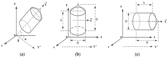
Figure 7.
Fragment flight orientation. (a) The first flight orientation. (b) The second flight orientation. (c) The third flight orientation.
Figure 7a presents one of the flight orientations. As it can be seen, the axis of the fragment obliquely intersects with the horizontal plane. Figure 7b presents the flight orientation where the fragment axis is vertical to the horizontal plane. Figure 7c presents the flight orientation that the fragment axis is parallel to the horizontal plane.
The first flight orientation of the fragment in Figure 7a follows the following rule: At , the fragment axis and the horizontal plane obliquely intersect. The windward area is the function of the angle parameters of and , and is expressed via the function of :
In the range of , the windward area is not a monotonic function. Thus, the following equation can be obtained via the derivative of Equation (13) with the parameters and :
where .
Additionally, . When , the function has the maximum value, and the corresponding parameters are as follows:
Then, these two parameters are substituted into Equation (13) and is solved to be equal to 51.42°. The maximum value of the windward area of the fragment is .
For the second flight orientation in Figure 7b, the fragment axis is vertical to the horizontal plane under the condition of . The windward area of the fragment is . Due to D = 14.3 mm, h = 14.3 mm, and H = 15.56 mm, it is obtained that .
For the third flight orientation in Figure 7c, the fragment axis is parallel to the horizontal plane under the condition of . The windward area of the fragment is . Due to D = 14.3 mm, .
In the actual experiments, the occurrence frequencies for different flight orientations are very difficult to obtain. According above calculation, the windward area S in the movement equation of the fragment is in the range of . For an object with random shapes that can rotate along the center of mass, the windward area is defined as a quarter of the surface area according to Cauchy’s law [26]. Consequently, the windward area for this fragment with a combination of a cylinder and a cone is equal to 241.525 mm2.
4.3. Data Fitting and Analysis
According to Figure 5, the average velocities of the fragment from the muzzle to the first target are always larger than that from the first target to the second target under different working conditions. This is because the aftereffect from the propellant combustion gas on the muzzle zone still acts on the fragment [44]. Thus, the deceleration distribution should exclude the influence of the muzzle aftereffect. Combined with Table 3, the movement equations for each launch of this fragment can be fitted as: and . The fitting parameters of distance–time equations of the fragment for different working conditions are shown in Table 4, and the fitting curves are presented in Figure 8. Table 5 also presents fitting parameters of fragment motion equation and the values of R2 of the fitting equations. Figure 9 presents distance–velocity fitting curves for different working conditions.
Table 4.
Fitting parameters of fragment distance–time.
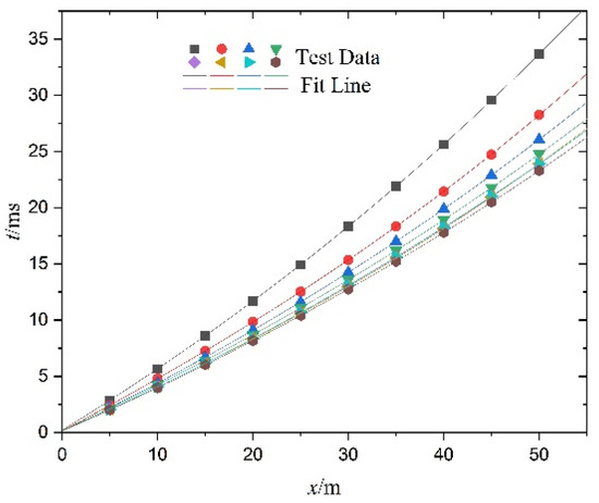
Figure 8.
Distance–time fitting curve.
Table 5.
Fitting parameters of fragment motion equation.
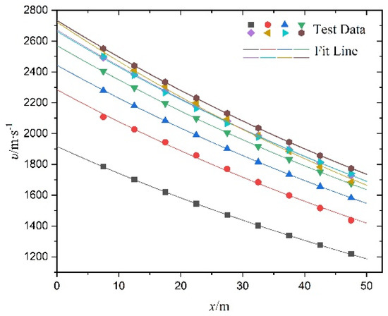
Figure 9.
Distance−velocity fitting curve.
It can be seen that the deceleration coefficient k has a small fluctuation, which is because the windward area of the fragment is continuously changing in the flight process. In sum, the average value of k is 0.009312 for the fragment in combination with a cylinder and a cone in Figure 8. In addition, the drag coefficient of the air cx can be calculated according to Equation (5), where m = 18.6 g, = 1.293 kg/m3 and S = 241.525 . Thus, it can be obtained that cx is equal to 1.109.
5. Conclusions
This work is focused on studying the deceleration and flight characteristics of the fragment in hypersonic speed. An experimental gun launch system with a large chamber, small caliber, and large length–diameter ratio is designed, and the corresponding test system is also established for observing the flight orientation of the fragment and tracking velocity distribution of the fragment via employing the zone interception velocity measurement, pressure transducer, and high-speed camera. The following conclusions are obtained in this work:
- The designed launch system with a large length–diameter ratio can successfully realize that the launch velocity of the standard fragment reaches 5−7 Ma. The sabot structure with four sections of different grooving depth can assure an effective separation of the sabot and the fragment after the projectile flies out of the muzzle. With an increase in the propellant charge, the chamber pressure and fragment velocity also increase.
- The established test system in the experiments can obtain the fragment velocity, chamber pressure curve, the flight orientation, and the separation process during the flight process of the fragment. In addition, the flight velocities under different propellant charges are also dealt with by a data post-processing.
- The mathematical model of flight orientation change of the fragment is established in this work to obtain the movement equation of the fragment in the flight process. According to the experimental data in the gun launch system, the deceleration coefficient is 0.009312, and the air drag coefficient is 1.109 for the cylinder-cone fragment with the velocity of 5−7 Ma by employing the least squares nonlinear regression fitting method and F verification.
Author Contributions
Conceptualization, J.H. and Y.Y.; Formal analysis, Methodology and Project administration, J.H.; Supervision, H.C. and Y.Y.; Writing—original draft, X.X.; Writing—review & editing, Z.F. and X.C. All authors have read and agreed to the published version of the manuscript.
Funding
This research received no external funding.
Institutional Review Board Statement
Not applicable.
Informed Consent Statement
Not applicable.
Data Availability Statement
Not applicable.
Conflicts of Interest
The authors declare no conflict of interest.
References
- Late, J.I. The transition to insensitive munitions (IM). Propellants Explos. Pyrotech. 1998, 23, 283–291. [Google Scholar]
- Fan, S.F.; Dong, P.; Li, X.; Liang, Z.F. Research progress in the safety of foreign naval ammunition. Chin. J. Explos. Propellants 2017, 40, 101–106. [Google Scholar]
- Zhang, Z.Z.; Zhang, H.; Yang, L.X.; Zhao, B.M.; Jing, J.W. Effect of constraint conditions on the sensitive characteristics of gun propellant charges under mechanical impact. Chin. J. Explos. Propellants 2018, 41, 192–196. [Google Scholar]
- Qin, L.X.; Liu, T.; Zhang, S.Q.; Yang, Y.B. Fragment shot-line model for air-defence warhead. Propellants Explos. Pyrotech. 2000, 22, 92–98. [Google Scholar]
- Baker, E.L.; Stasio, A.R. Insensitive munitions technology development. Problemy Mechatroniki Uzbrojenie Lotnictwo Inżynieria Bezpieczeństwa 2014, 5, 7–20. [Google Scholar]
- Demay, S.C.; Thelen, C.J. Insensitive munitions propulsion progress. Int. J. Energetic Mater. Chem. Propuls. 1997, 4, 1–6. [Google Scholar]
- Powell, I.J. Insensitive munitions–design principles and technology developments. Propellants Explos. Pyrotech. 2016, 41, 409–413. [Google Scholar] [CrossRef]
- Hatch-Aguilar, T.; Najjar, F.; Szymanski, E. Computational Hydrocode Study of Target Damage due to Fragment-Blast Impact. In Proceedings of the 26th International Symposium of Ballistics, Miami, FL, USA, 12–16 September 2011. [Google Scholar]
- Naik, G.; Chinchanikar, S. Estimating primary fragment characteristics during hypervelocity impact of spherical fragment on thin plate using artificial neural network. In Proceedings of the 31st International Symposium on Ballistics, Hyderabad, India, 4–8 November 2019. [Google Scholar]
- Singh, S.; Srikanth, C.; Dixit, V.K. Prediction of spatial distribution of fragments from a preformed fragmentation warhead using mathematically constructed model. In Proceedings of the International Symposium on Ballistics, Long Beach, CA, USA, 11–15 September 2017. [Google Scholar]
- Graswald, M.; Brown, R.E.; Sinibaldi, J.O.; Nolte, T.; Hendrik, R. Vulnerability of Mortar Projectiles by Intercepting Fragmentation Warheads. In Proceedings of the 25th International Symposium on Ballistics, Beijing, China, 17–21 May 2010. [Google Scholar]
- Lynch, N.J.; Nyogeri, L.; Church, P.D. Improving the design capability for fragment protection. In Proceedings of the 26th International Ballistics Symposium, Miami, FL, USA, 12–16 September 2011. [Google Scholar]
- Haskins, P.J.; Briggs, R.I.; Leeming, D.W.; White, N.; Cheese, P. Dual fragment impact of PBX charges. proceedings of the conference of the American physical society topical group on shock compression of condensed matter. In Proceedings of the American Physical Society, St. Louis, MO, USA, 9–14 July 2017. [Google Scholar]
- Cook, M.D.; Haskins, P.J.; Briggs, R.I. Fragment impact characterization of melt-cast and PBX explosives. AIP Conf. Proc. 2002, 620, 1047–1050. [Google Scholar]
- Quan, J.L.; Miao, R.Y.; Liang, Z.F. Velocity attenuation rule of different prefabricated fragments and correction of windward area. Explos. Mater. 2019, 48, 28–32. [Google Scholar]
- Voort, M.V.D.; Baker, E.L. Ballistics trajectory and impact analysis for fragment impact testing insensitive munitions and hazard classification project criteria. AIP Conf. Proc. 2018, 1979, 120007. [Google Scholar]
- Tomasello, K.; Baker, E.L.; Al-Shehab, N.; Kennison, K.; Hunter, D. Fragment impact gun testing technology and issues. In Proceedings of the Insensitive Munitions & Energetic Materials Technology Symposium, Rome, Italy, 18–21 May 2015. [Google Scholar]
- Baker, E.L.; Al-Shehab, N.; Miers, K.; Pudlak, D. Insensitive munitions fragment impact gun testing technology challenges. Propellants Explos. Pyrotech. 2016, 41, 572–579. [Google Scholar] [CrossRef]
- Morrison, F.A. Data Correlation for Drag Coefficient for Sphere. Ph.D. Thesis, Department of Chemical Engineering, Michigan Technological University, Houghton, MI, USA, 2013. [Google Scholar]
- Singh, N.; Kroells, M.; Li, C.X.; Ching, E.; Ihme, M.; Hogan, C.J.; Schwartzentruber, T.E. General drag coefficient for flow over spherical particles. AIAA J. 2022, 60, 587–597. [Google Scholar] [CrossRef]
- Goossens, W.R. Review of the empirical correlations for the drag coefficient of rigid spheres. Powder Technol. 2019, 352, 350–359. [Google Scholar] [CrossRef]
- Loth, E.; Daspit, J.T.; Jeong, M.; Nagata, T.; Nonomura, T. Supersonic and hypersonic drag coefficients for a sphere. AIAA J. 2021, 59, 3261–3274. [Google Scholar] [CrossRef]
- Zhou, C.J.; Su, J.; Chen, H.K.; Shi, Z.Y. Terminal velocity and drag coefficient models for disc-shaped particles based on the imaging experiment. Powder Technol. 2022, 398, 117062. [Google Scholar] [CrossRef]
- Hu, J.; Du, J.Y.; Chen, H.; Cao, P.; Zhang, Y.J. Research progress of fragment impact insensitive ammunition. J. Ordnance Equip. Eng. 2022, 43, 36–43. [Google Scholar]
- Ma, Y.Z.; Li, Q.X.; Yang, G. The discussion of the velocity attenuate regularity of projectile fragments. J. Proj. Rocket. Missiles Guid. 2000, 3, 59–64. [Google Scholar]
- Ma, Y.Y. A study on the velocity dampings and penetrating depth of small preformed fragments. Acta Armamentarii 1981, 1, 52–58. [Google Scholar]
- Yang, G.H.; Wang, G.J.; Gong, Y.Q.; Sun, Y.Q. Experimental study on flying laws detonation driven precast fragments by comb targets method. Chin. J. Energetic Mater. 2013, 21, 656–659. [Google Scholar]
- Wang, L.; Gao, X.J.; Li, X.H. The terminal effect parameters test method research on the high explosive shell natural fragments. J. Proj. Rocket. Missiles Guid. 2021, 41, 125–128. [Google Scholar]
- Tan, D.W.; Wang, G.J.; Gong, Y.Q.; Gao, N. Experimental studies on air drag coefficient of spherical tungsten fragments. Chin. J. High Press. Phys. 2007, 21, 231–236. [Google Scholar]
- Wang, Z.; Kong, X.Y.; Wu, W.G. Velocity attenuation characteristics of high-velocity fragments penetrating. Acta Armamentarii 2021, 42, 167–172. [Google Scholar]
- Xin, D.J.; Xue, K. Artificial neural network-based prediction model for the air drag coefficient of non-spherical fragments. Acta Armamentarii 2022, 43, 1083. [Google Scholar]
- NATO. STANDARD, AOP-4496; Fragment Impact Test Procedures for Munitions. North Atlantic Treaty Organization. Nato Standardization Office: Brussels, Belgium, 2019. [Google Scholar]
- Hu, J.; Chen, H.; Yu, Y.G.; Xue, X.X.; Fu, Y. High-velocity metal fragment: Motion characteristic and optimization design. Appl. Sci. 2022, 12, 9922. [Google Scholar] [CrossRef]
- Grady, D.E. Local inertial effects in dynamic fragmentation. J. Appl. Phys. 1982, 53, 322–325. [Google Scholar] [CrossRef]
- Kipp, M.E.; Grady, D.E. Dynamic fracture growth and interaction in one dimension. J. Mech. Phys. Solids 1985, 33, 399–415. [Google Scholar] [CrossRef]
- Glenn, L.A.; Chudnovsky, A. Strain-energy effects on dynamic fragmentation. J. Appl. Phys. 1986, 59, 1379–1380. [Google Scholar] [CrossRef]
- Englmant, R.; Rivier, N.; Jaeger, Z. Fragment-size distribution in disintegration by maximum-entropy formalism. Philos. Mag. Part B 1987, 50, 751–769. [Google Scholar] [CrossRef]
- Grady, D.E.; Passman, S.L. Stability and fragmentation of ejecta in hypervelocity impact. Int. J. Impact Eng. 1989, 10, 197–212. [Google Scholar] [CrossRef]
- Silvestrov, V.V. Fragmentation of a steel sphere by a high-velocity impact on a highly porous thin bumper. Combust. Explos. Shock Waves 2004, 40, 238–252. [Google Scholar] [CrossRef]
- Colton, B.C.; Kevin, J.H.; Connor, W.; Michelle, L.P.; Joseph, A.; Casey, M. High velocity impact testing for evaluation of intermetallic projectiles. J. Dyn. Behav. Mater. 2020, 6, 236–245. [Google Scholar]
- Myagkov, N.N. Scaling invariance of spherical projectile fragmentation upon high-velocity impact on a thin continuous shield. J. Exp. Theor. Phys. 2017, 124, 57–69. [Google Scholar] [CrossRef]
- Teng, T.L.; Chu, Y.A.; Chang, F.A. Design and implementation of a high-velocity projectile generator. Combust. Explos. Shock Waves 2007, 43, 233–240. [Google Scholar] [CrossRef]
- Li, L.P. Investigation on Some Key Measuring Technologies of Fragment Warhead Power Field. Master’s Thesis, Nanjing University of Science and Technology, Nanjing, China, 2017. [Google Scholar]
- Shi, Z.J.; Jiang, C.L. Analysis of velocity decay property and ballistic limit of different shape pre-formed fragment. J. Proj. Rocket. Missiles Guid. 2004, S2, 312–314. [Google Scholar]
Disclaimer/Publisher’s Note: The statements, opinions and data contained in all publications are solely those of the individual author(s) and contributor(s) and not of MDPI and/or the editor(s). MDPI and/or the editor(s) disclaim responsibility for any injury to people or property resulting from any ideas, methods, instructions or products referred to in the content. |
© 2023 by the authors. Licensee MDPI, Basel, Switzerland. This article is an open access article distributed under the terms and conditions of the Creative Commons Attribution (CC BY) license (https://creativecommons.org/licenses/by/4.0/).