1. Introduction
Redundantly actuated systems, which employ multiple actuators to drive the same degrees of freedom, have attracted significant attention due to their potential to enhance performance and flexibility in various engineering applications. In the presence of actuation constraints, the achievable ranges of velocity and force are inherently limited, making performance analysis under such constraints a critical issue in system design and operation. Previous studies have primarily investigated velocity and force capabilities separately, leading to the development of various performance measures for evaluating system behavior within the workspace. Representative approaches include velocity-based manipulability analysis [
1] and force capability analysis [
2], as well as geometric interpretations that relate kinematic and dynamic performance [
3]. However, despite the fact that velocity and force share the same actuation resources and are intrinsically coupled, their relationship has not been systematically analyzed in an integrated manner.
Although a variety of actuation systems have been investigated, including artificial muscle actuators [
4] and hydraulic/pneumatic actuators [
5,
6], geared electromagnetic motors are currently the most widely used owing to their simple system design and control.
Various efforts have been made to improve actuator performance at the component level [
7,
8,
9]. At the system level, different actuation mechanisms have been explored to enhance manipulation performance. Underactuation mechanisms [
10,
11] enable increased degrees of freedom at the cost of dexterity, while force amplification mechanisms [
12,
13] improve force generation capability. Redundant actuation mechanisms provide additional flexibility by introducing extra actuation degrees of freedom, enabling tasks such as fault tolerance [
14], obstacle avoidance [
15], and performance optimization [
16]. In particular, distributed actuation mechanisms (DAMs) have demonstrated the capability to enhance manipulation performance by redistributing actuation resources without altering the system configuration [
17,
18].
To quantitatively evaluate manipulator performance, various performance indices have been proposed in the literature. In addition, optimization-based approaches have been widely adopted to analyze system performance under constraints [
19,
20,
21,
22].
The manipulability index [
1] is widely used to characterize velocity capability, while force-related performance measures have also been developed based on similar principles [
23]. The manipulability index provides a geometric interpretation of velocity capability by mapping joint-space actuation variables to the end-effector space through the Jacobian matrix. However, such transformation-based approaches primarily characterize the distribution of performance and do not explicitly quantify the maximum achievable performance under actuation constraints.
Optimization-based approaches have been introduced to evaluate force capability in redundantly actuated systems [
16], and the concept of allowable load sets has been proposed to define feasible load regions under structural constraints [
24]. In addition, recent studies in applied mathematics have explored optimization-based modeling and performance analysis of constrained dynamical systems, providing generalized frameworks for system-level analysis [
25,
26,
27,
28]. Despite these advances, existing approaches typically treat velocity and force as separate performance measures, and their coupled relationship has not been explicitly addressed.
In systems subject to actuation constraints, velocity and force exhibit interrelated performance characteristics due to their reliance on shared actuation resources. Depending on task requirements, this relationship may manifest as complementary behavior between velocity and force, and its quantitative analysis plays an important role in understanding system performance. However, existing studies have often treated velocity and force as independent performance measures, and efforts to analyze their relationship from an integrated perspective have been relatively limited. Therefore, a systematic approach is required to characterize and interpret the relationship between velocity and force under constrained actuation conditions.
To address this gap, an optimization-based framework is developed to characterize velocity and force along specified directions by incorporating system kinematics and actuator limits. Through directional optimization, the achievable performance is evaluated, and the resulting directional performance distributions are systematically characterized. This formulation enables a unified analysis of velocity and force under identical actuation constraints, providing a structured basis for interpreting their relationship under constrained conditions. A distributed actuation mechanism is considered as a representative system to demonstrate the proposed formulation. Furthermore, a gait-inspired motion is considered to illustrate how the proposed framework can be utilized for motion generation under phase-dependent performance requirements.
The main contributions of this study are summarized as follows:
- (1)
A unified optimization-based framework is proposed to analyze the coupled relationship between velocity and force in redundantly actuated systems under identical actuation constraints, addressing the limitation of conventional approaches that treat them separately.
- (2)
A direction-based optimization approach is introduced to systematically characterize the achievable velocity and force as directional performance distributions, enabling quantitative evaluation of their coupling behavior and inherent trade-offs.
- (3)
The applicability of the proposed framework is demonstrated through a gait-inspired motion example, showing how phase-dependent velocity–force characteristics can be effectively utilized for performance-oriented motion generation.
The remainder of this paper is organized as follows. In
Section 2, the end-effector velocity and force of a three-link planar manipulator are derived mathematically, and the optimization-based analysis framework is introduced.
Section 3 presents the optimization results and analysis of the velocity–force relationship.
Section 4 describes the application to gait-inspired motion. Finally,
Section 5 concludes the paper.
2. Optimization-Based Analysis of Velocity–Force Duality
2.1. Kinematic and Static Modeling of Velocity and Force
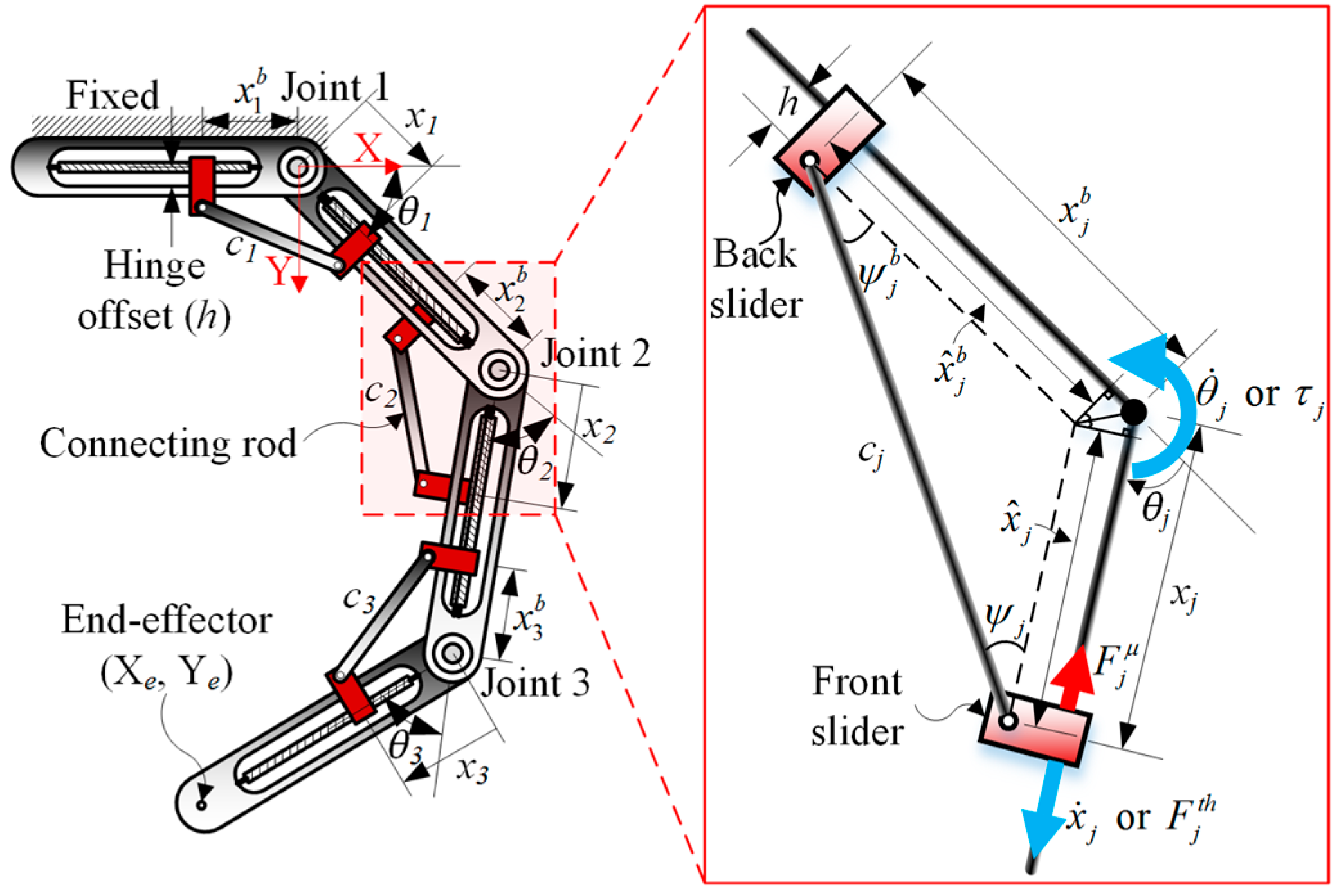
In this study, a three-link planar manipulator based on a distributed actuation mechanism (DAM), as shown in
Figure 1, is considered as the representative system. The manipulator consists of three joints, each comprising two sliders and a connecting rod. To establish the relationship between actuation variables and end-effector performance, kinematic and static models are formulated under the following assumptions: (i) the end-effector is fixed at a target position, (ii) only the front sliders are activated for manipulation, and (iii) friction is modeled using the Coulomb friction model.
The end-effector is fixed to evaluate directional performance at a given position, and the framework can be applied across the workspace. The use of only the front sliders represents a specific actuation configuration, while the Coulomb friction model is adopted for simplicity; these assumptions may affect quantitative results but do not alter the overall analysis framework.
Considering the offset between the hinge joint and slider (
h in
Figure 1), the relationship between the joint angle (
θj) and slider positions (
xj) can be expressed as follows:
where
;
;
;
cj is the connecting rod length;
h is the hinge offset; and
xj and
are the positions of the front and back sliders at the
jth joint, respectively. By differentiating (1) with respect to time, the angular velocity of the
jth joint can be obtained as follows:
where
is the speed of the front and back sliders and
.
Because the endpoint of the manipulator is a function of the joint angles, the velocity at the endpoint (or end-effector velocity)
can be derived by differentiating the endpoint with respect to time as follows:
where
. In (3), the Jacobian matrix
is defined as
where
l1,
l2, and
l3 denote the lengths of the first, second, and third links, respectively.
In a previous study [
17], the joint torque generated at the
jth joint was derived as follows:
where
, and
and
μj are the thrusting force and Coulomb friction coefficient at joint
j, respectively. In this study, using the pseudo-inverse method [
29], the force at the endpoint (or end-effector force)
was derived as follows:
where
. These kinematic and static models provide a unified representation of velocity and force with respect to actuation variables, enabling a consistent formulation for evaluating their directional characteristics under identical actuation constraints. This formulation serves as the basis for the subsequent optimization-based analysis.
2.2. Optimization-Based Characterization of Velocity and Force
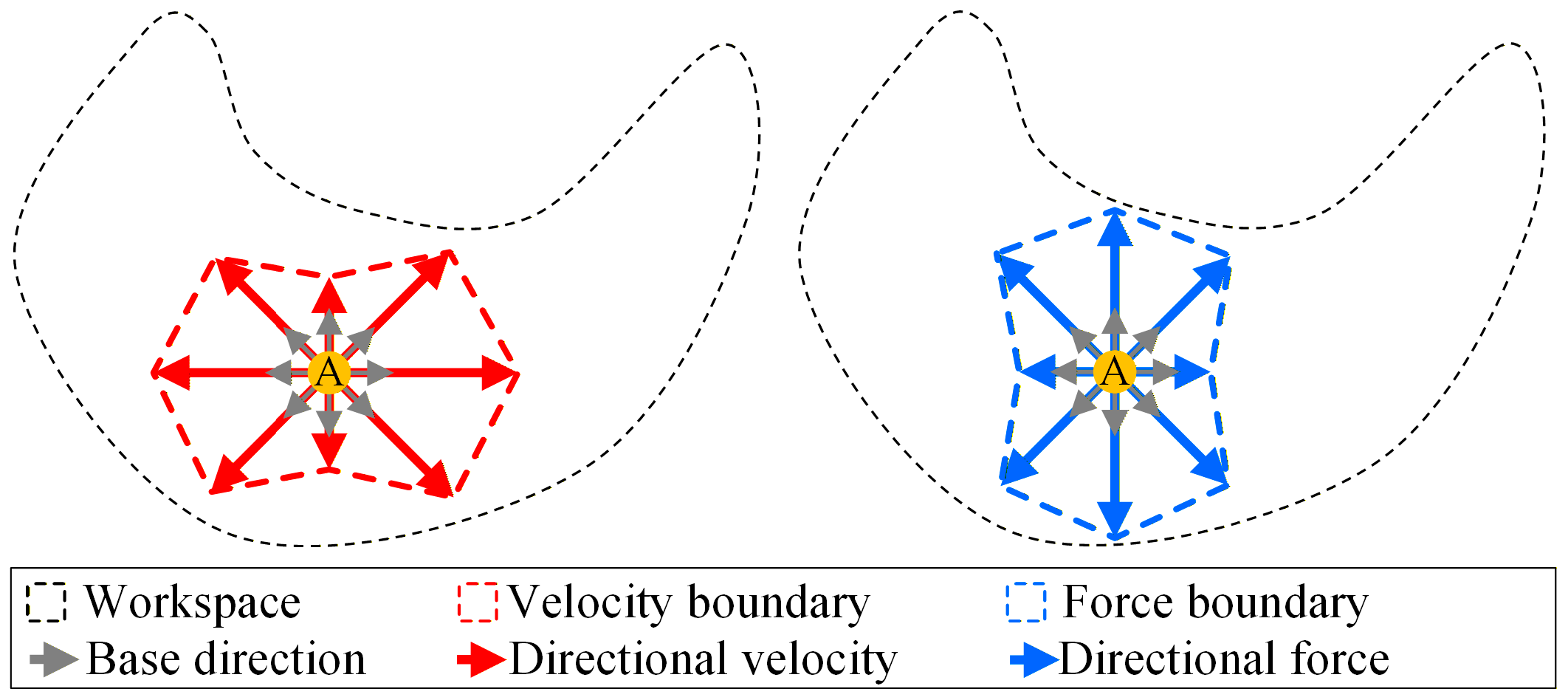
To characterize the directional performance of velocity and force under actuation constraints, an optimization-based formulation is developed. For a given target position (any endpoint
A in
Figure 2), a unit direction vector is defined to evaluate the performance of the end effector along a specified direction (gray arrows in
Figure 2). The velocity and force along this direction are obtained by solving constrained optimization problems that incorporate actuator limits and system kinematics.
Specifically, the velocity and force along a given direction are defined as the projections of the end-effector velocity and force onto the unit direction vector. The optimization problem is then formulated to maximize these directional components subject to actuation constraints, including bounds on actuator velocities, forces, and joint variables. In addition, a constraint on power consistency is imposed to ensure physically feasible operation of the system.
To determine the optimal directional values of the end-effector velocity and force, an optimization formulation was established as follows:
where
θ1 is the first joint angle;
xj is the position of the front slider at joint
j;
is the thrusting force at joint
j; and
is the moving speed of the front slider at joint
j. Subscript
i denotes the number of base directions, whereas superscripts (
l) and (
u) denote the lower and upper bounds, respectively. In (7) and (8), objective functions
f1 and
f2 represent the end-effector force and velocity, respectively, along the unit base direction
di. Constraint function
g imposes zero or positive power consumption at the end effector for practical implementation.
By solving the optimization problem over multiple directions, the directional performance of velocity and force can be systematically evaluated. The resulting set of optimal values provides a comprehensive representation of the directional performance distribution across different directions. This representation enables a consistent interpretation of velocity and force within a unified analytical framework and facilitates the examination of their relationship under constrained actuation conditions.
It is noted that the proposed optimization problem involves nonlinear constraints with trigonometric terms, and the feasible region is not guaranteed to be convex. Consequently, the uniqueness of the optimal solution cannot be theoretically ensured. However, the objective of this study is to characterize directional performance under given actuation constraints, and consistent solutions are obtained using a sequential quadratic programming (SQP) approach.
Based on this formulation, the relationship between velocity and force can be analyzed by comparing their directional characteristics under identical system conditions. The proposed approach provides a structured basis for evaluating performance trade-offs and supports performance-oriented decision-making for task execution.
3. Optimization Results and Analysis of Velocity–Force Relationship
To evaluate the proposed optimization-based framework, numerical analyses are conducted to characterize the velocity and force of the end effector across multiple target positions in the workspace. A set of evenly distributed target positions is selected, and directional evaluations are conducted using a predefined set of unit directions. The optimization problems described in (7) and (8) are solved to obtain the directional velocity and force performance under identical actuation constraints.
The parameters used in the optimization are listed in
Table 1. Seven design variables were used and sixteen base directions were used to represent the directional performance distributions (
M = 16 in (7) and (8)). The joint angles,
θ1,
θ2, and
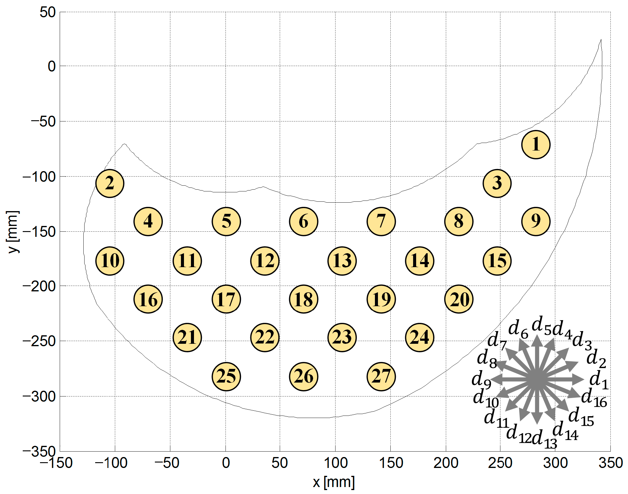
θ3, were bounded between 20° and 90° to avoid singularity. Only the front sliders were activated for actuation; therefore, the thrust force and velocity of the back sliders were set to zero. Through optimization, the resulting directional performances at the end effector were determined along 16 base directions for 27 target positions that were equidistantly distributed in the workspace (
Figure 3). SQP using the fmincon function in MATLAB R2024b was used to solve the optimization problems [
30].
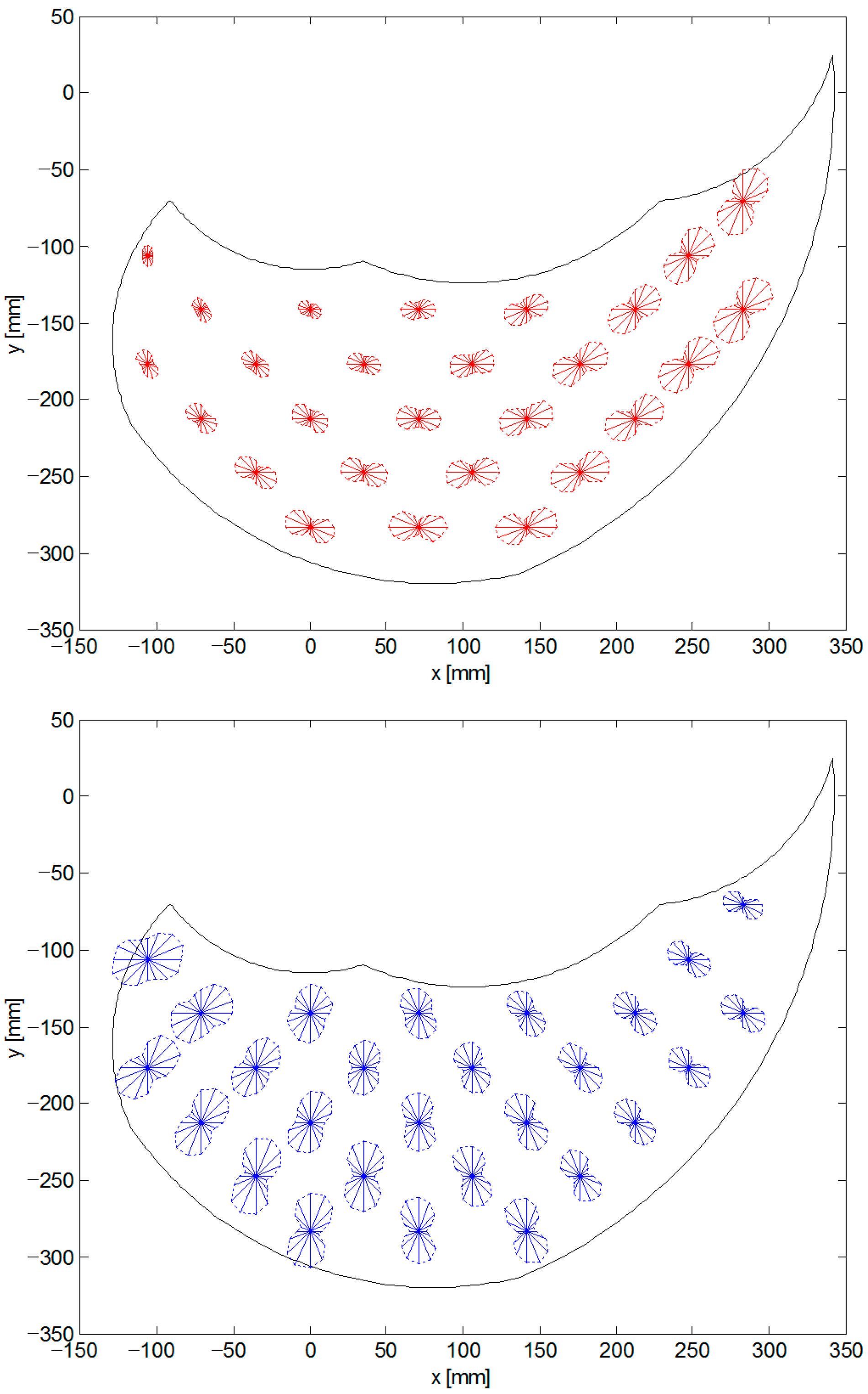
Figure 4 illustrates the directional distributions of velocity and force at the target positions. Each vertex corresponds to the optimal value of velocity or force along a given direction.
Interestingly, a typical serial manipulator offers the manipulability of an elliptical shape [
27], whereas the proposed DAM-based manipulator exhibits directional velocity and force distributions forming a figure-of-eight shape. This is primarily because the DAM-based manipulator has additional DOFs in actuation (i.e., the slider position in each link). As shown in
Figure 4, the velocity capability tends to be larger in the tangential direction (from the origin of manipulation), whereas the force capability is more pronounced in the radial direction. Additionally, the velocity-dominant regions are located in the upper right of the workspace, whereas the force-dominant regions appear in the lower left. These results indicate that velocity and force exhibit complementary directional characteristics in the DAM-based manipulator. By systematically evaluating the performance across multiple directions, it becomes possible to estimate the direction-dependent velocity and force of the manipulator along a specific direction at a given target position. Therefore, the proposed framework provides a basis for performance-oriented trajectory design under actuation constraints.
The directional performance characteristics of the DAM-based manipulator are further examined.
Table 2 presents representative optimization results for velocity- and force-oriented conditions at target position 17 along unit direction 13 in
Figure 3. At the same target position, the velocity-oriented condition yields a velocity of 40.5 mm/s and a force of 16.3 N, whereas the force-oriented condition produces a velocity of 29.6 mm/s and a force of 51.9 N. These results indicate that the end effector can move 1.37 times faster under the velocity-oriented condition, while it can generate 3.18 times larger force under the force-oriented condition, compared with the corresponding alternative condition. It is noted that the optimal solutions are obtained without requiring all actuation variables to reach their prescribed bounds (e.g.,
in
Table 1). The observed performance differences arise from variations in actuation configuration, including joint angles, slider positions, and thrusting parameters, as summarized in
Table 2.
To further examine the characteristics of the proposed framework, comparative analyses are conducted under higher- and lower-performance conditions. The minimum performance levels are obtained using a similar optimization procedure, while maintaining identical thrusting parameters for a consistent comparison.
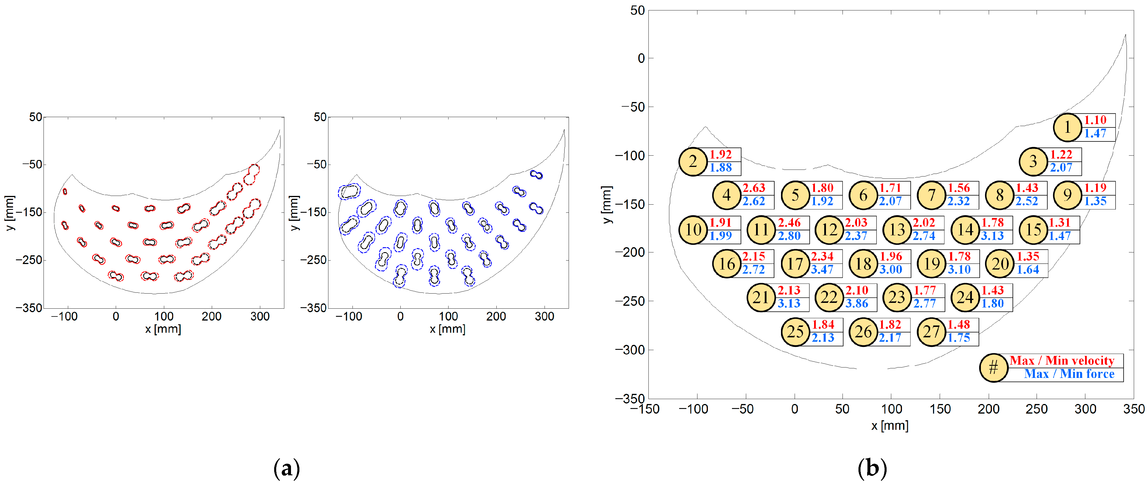
Figure 5a presents a comparison between the higher-performance cases (red dotted line for velocity and blue dotted line for force) and the lower-performance cases (black solid lines). Although the thrusting parameters are fixed in both cases, the manipulation performance in the higher-performance cases is significantly improved by optimally adjusting the actuation configuration, including slider positions and joint angles.
As shown in
Figure 5b, the ratio of maximum to minimum performance varies significantly depending on the target position. Larger ratios are observed at positions where the manipulator can adopt a more flexed configuration. For example, the maximum-to-minimum velocity ratio reaches 2.46 at position 11, and the corresponding force ratio reaches 3.86 at position 22. In these cases, the increased flexibility in joint motion allows for a wider range of feasible actuation configurations, resulting in greater variations in velocity and force performance.
In contrast, relatively small ratios are observed at positions such as 9, 15, 20, 24, and 27. These positions correspond to configurations where the manipulator is nearly fully extended, resulting in a limited range of joint motion. Consequently, the variation in actuation variables during optimization is restricted, leading to smaller differences between the maximum and minimum performance.
These results indicate that the extent of performance variation is strongly influenced by the kinematic configuration of the manipulator, with flexed configurations enabling greater variability and fully extended configurations limiting performance variation.
Consequently, the proposed framework enables efficient utilization of actuator capacity under given constraints and provides a basis for performance-oriented system design and trajectory planning.
4. Application to Gait-Inspired Motion
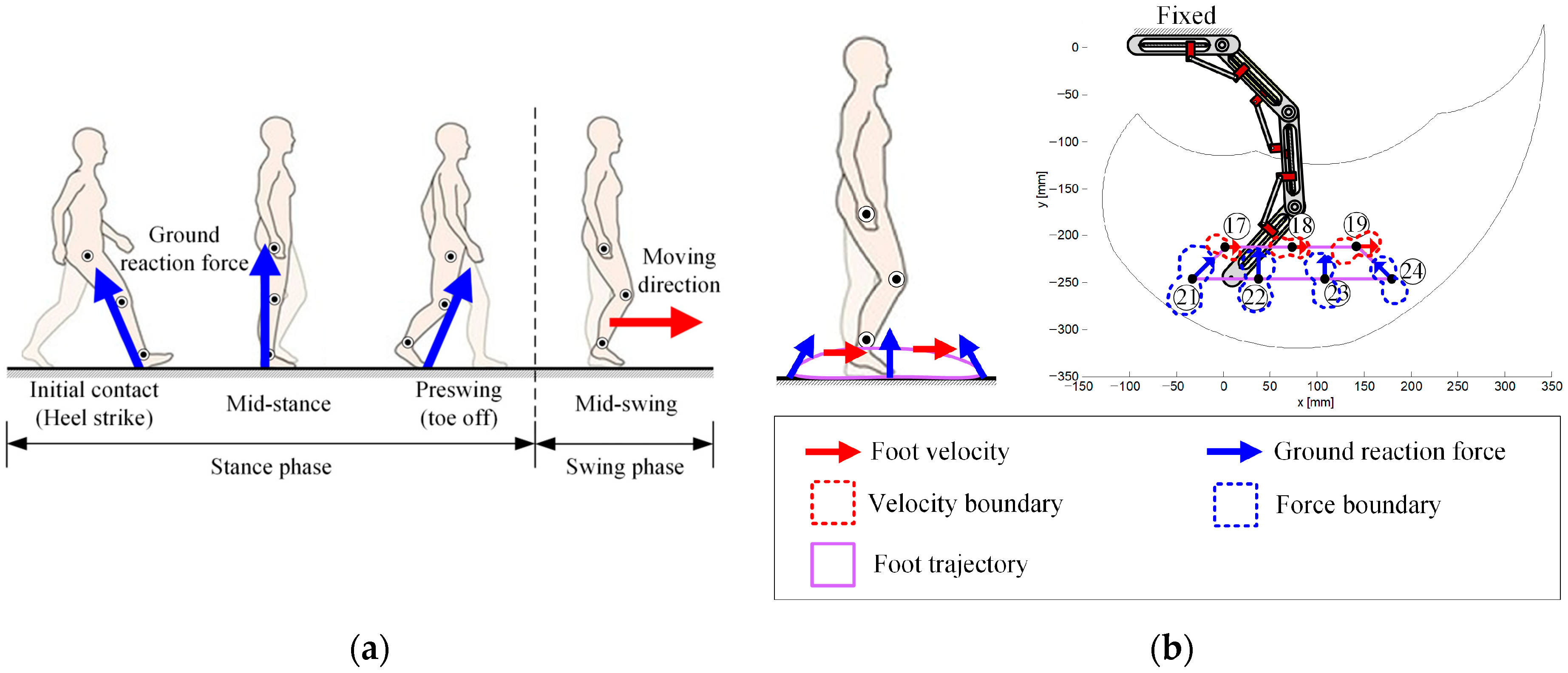
In nature, human gait provides a representative example of motion involving phase-dependent performance requirements, where the lower limb alternates between stance and swing phases. As shown in
Figure 6a, the stance phase begins with a heel strike, during which the foot must exert a relatively large force to withstand the ground reaction force. At mid-stance, the ground reaction force direction is approximately perpendicular to the ground, while at toe-off, it shifts forward. In contrast, during the swing phase, rapid foot motion is required to reposition the limb for the next step. These characteristics indicate that locomotion involves varying demands on force and velocity depending on the motion phase.
The DAM-based three-link planar manipulator exhibits a geometric analogy to a lower limb with three joints (i.e., the hip, knee, and ankle joints), providing a suitable platform for illustrating the proposed framework. The directional characteristics of force observed at selected target positions correspond to those required during the stance phase, while the velocity-dominant directions align with the motion requirements of the swing phase. In particular, the sequence of target positions 17–18–19 forms a trajectory consistent with rapid forward motion, reflecting the characteristics of the swing phase.
Furthermore, the directional force characteristics at target positions 24, 22 (or 23), and 21 correspond to the force requirements during heel-strike, mid-stance, and toe-off, respectively. Similarly, the velocity-dominant directions at target positions 17, 18, and 19 are aligned with horizontal motion, representing efficient forward progression during the swing phase. These observations indicate that the directional performance characteristics obtained from the proposed framework can be associated with phase-dependent motion requirements.
Therefore, the proposed framework provides a basis for constructing gait-like trajectories by appropriately selecting direction-dependent velocity and force characteristics. This example highlights the applicability of the framework for motion generation under varying performance requirements.
5. Conclusions
This study presented an optimization-based framework for analyzing the relationship between velocity and force in a distributed actuation mechanism (DAM). By formulating velocity and force in a unified manner based on kinematic and static models, the proposed approach enables a systematic characterization of end-effector performance under actuation constraints. The directional evaluation of velocity and force provides a consistent basis for interpreting their relationship, revealing their complementary and direction-dependent characteristics depending on the direction and configuration of the system.
The numerical results demonstrated that the performance of velocity and force varies significantly across the workspace and is strongly influenced by the allocation of actuation variables. The analysis showed that configurations favoring velocity tend to reduce force capability, and vice versa, indicating an inherent trade-off between the two performance measures. These findings highlight the importance of jointly considering velocity and force simultaneously when evaluating system performance.
In addition, the applicability of the proposed framework was illustrated through a gait-inspired motion example, where phase-dependent performance requirements were effectively reflected in trajectory construction. This example demonstrates that the proposed approach can be utilized to support motion planning tasks involving varying performance demands.
Overall, the proposed framework provides a structured and consistent approach for analyzing and utilizing velocity and force characteristics in distributed actuation systems, contributing to a deeper understanding of performance trade-offs and their implications for system design and control. The proposed framework is not limited to the specific manipulator considered in this study and has potential applicability to other engineering systems involving coupled velocity–force characteristics, such as vehicle and suspension systems [
32]. Future work will address the robustness of the proposed framework under practical conditions, including sensor noise, mechanical uncertainties, and external disturbances.