
Article

LQR-Tuned Self-Regulating Sliding Mode Control of a Boost Converter for Robust Voltage Regulation in DC Microgrids


1
Department of Electrical Engineering, National University of Computer and Emerging Sciences, Lahore 54000, Pakistan
2
Institut d’Électronique et des Technologies du numéRique (IETR), Nantes Université Rue Christian Pauc, 44300 Nantes, France
3
College of Engineering and Energy, Abdullah Al Salem University, Khaldiya, Kuwait
*
Author to whom correspondence should be addressed.
Mathematics 2026, 14(6), 1030; https://doi.org/10.3390/math14061030
Submission received: 19 February 2026 / Revised: 8 March 2026 / Accepted: 14 March 2026 / Published: 18 March 2026

Abstract

This paper presents a hybrid control strategy for robust voltage regulation of a DC–DC boost converter used in a renewable-rich DC microgrid. The DC microgrid may comprise batteries, photovoltaic, and wind energy sources connected to a common DC bus, where voltage fluctuations arise due to variable generation and dynamic load profiles. To ensure optimal and efficient output voltage regulation under these conditions, a novel Linear Quadratic Regulator (LQR) driven self-regulating Sliding Mode Control (SMC) approach is developed. The proposed scheme is realized by combining the optimal performance of an LQR voltage-reference tracking controller with the robustness of a tangent-hyperbolic-based-sliding-mode reaching law defined over an LQR-driven sliding surface. To reduce chattering and improve adaptability to bounded disturbances, the waveform of the hyperbolic switching function in the reaching law is adaptively modulated via an online indirect supervised learning law. The control parameters are tuned offline using numerical optimization. Simulation results under different scenarios, including input voltage disturbances, load variations, and model uncertainties, show that the proposed method achieves superior voltage regulation, reduced chattering, and enhanced dynamic response compared to conventional controllers. The framework ensures reliable EV integration into intelligent DC microgrids.

1. Introduction

The rapid growth of electric vehicles (EVs) has intensified demand for efficient and reliable battery charging solutions within renewable-integrated DC microgrids [1]. In such systems, DC–DC boost converters play a pivotal role by stepping up low and variable source voltages, primarily originating from batteries, photovoltaic arrays, or hybrid energy storage units, to the desired regulated levels [2]. Owing to their high efficiency, simple topology, and fast dynamic response, boost converters are widely deployed in DC microgrid applications [3]. However, maintaining stable output voltage regulation remains a critical challenge [4]. The voltage regulation in DC–DC conversion is frequently subject to exogenous disturbances arising from load step transients, parametric uncertainties, and input voltage fluctuations due to the inherently unpredictable nature of renewable energy sources [5]. These factors collectively degrade regulation performance, thereby necessitating robust and adaptive closed-loop control strategies to ensure stable and efficient voltage regulation in boost converters [6].

1.1. Literature Review

Numerous closed-loop regulation strategies have been proposed to optimize the voltage regulation in DC–DC boost converters [7,8]. Conventional Proportional–Integral–Derivative (PID) controllers remain popular due to their structural simplicity and reliable performance [9]. However, their limited degrees of freedom restrict robustness against nonlinearities and exogenous disturbances [10]. Fractional-order and complex-order PID extensions enhance the controller’s design flexibility and disturbance rejection by introducing additional tuning hyperparameters [11,12]. Although their offline optimization is computationally demanding [13]. Intelligent paradigms, including neural and fuzzy control schemes, offer agile regulation [14]. However, neural controllers require extensive training datasets for accurate inverse control modeling [15], whereas the pervasive fuzzy systems rely on expert-defined rule bases that introduce subjectivity and imprecision, along with significant computational overhead [16].
Optimal control approaches, such as the Linear Quadratic Regulator (LQR) and its integral tracking variant, minimize quadratic performance indices to yield optimal state-feedback control decisions [17,18]. However, their model-dependent structure limits its resilience to parametric uncertainties and disturbances [19,20]. The Model Predictive Control (MPC) improves constraint handling and predictive optimization, though its real-time deployment is often hindered by high computational complexity [21,22]. The ubiquitous Sliding-Mode-Control (SMC) is a robust nonlinear control strategy that provides strong resilience against external perturbations by enforcing motion along predefined sliding manifolds [23,24]. It has been widely applied for output voltage regulation under load and input disturbances [25,26,27]. Despite these merits, the discontinuous switching action inherent to SMC produces high-frequency oscillation, commonly referred to as chattering, in the control signal [28]. In the context of voltage regulation, such oscillations translate into undesirable ripples in state trajectories, which may be hazardous to the load [29]. To alleviate this issue, hybrid approaches, such as adaptive and observer-based backstepping-integral SMC, have also been explored [30,31]. These schemes tend to mitigate chattering and improve estimation accuracy but lack resilience against large perturbations [32]. The robust H-infinity control effectively attenuates worst-case disturbances, but its inherently conservative design often results in suboptimal performance [33].
Adaptive control strategies address parameter variability by self-tuning controller gains online in response to exogenous perturbations [34,35]. However, the algorithmic complexity of adaptive schemes can increase computational demand and may introduce stability concerns during rapid state transitions [36,37]. More recently, reinforcement learning (RL) techniques have gained traction in voltage regulation through predictive analytics and regression capabilities [38]. Despite their promising performance, RL-based solutions require extensive datasets, lengthy training, and substantial computational resources, which limit their practicality for real-time voltage regulation systems [39].
From the foregoing discussion, it is evident that LQR-based schemes are well-suited for applications requiring optimal control effort and guaranteed asymptotic stability, whereas SMC strategies excel in rejecting bounded disturbances and parametric uncertainties [40]. A voltage regulation system for a DC–DC converter inherently demands both attributes. Specifically, it requires accurate reference tracking under load disturbances, robust disturbance rejection and optimal control trajectories while preserving the system’s asymptotic stability, thereby motivating the development of hybrid optimal-robust control frameworks.

1.2. Principal Contributions

The principal contribution of this article is the development of a robust optimal collaborative voltage regulation framework for a DC–DC boost converter to ensure precise output voltage regulation under load disturbances, parametric uncertainties, and input voltage fluctuations inherent to renewable-integrated microgrids. The boost converter’s nominal state space model is employed to design a baseline LQR, which serves as the baseline optimal controller and benchmark for performance evaluation.
To achieve the desired control objectives, an LQR-driven Self-Regulating SMC (LQ-SRSMC) scheme is formulated in this work, wherein the baseline LQR control action is embedded within the sliding surface dynamics to preserve optimality while enhancing robustness against bounded disturbances. To improve the proposed hybrid controller’s adaptability and mitigate chattering (an inherent limitation of classical SMC), the variation rate of the SMC law’s inner hyperbolic switching function is self-regulated via an online adaptation mechanism. The key methodological contributions are summarized as follows:
  • Formulation of an LQR-driven sliding surface, where the optimal control input guides the SMC manifold design.
  • Synthesis of a hybrid LQR–SMC control law that synergistically combines optimality with robustness, supported by closed-loop stability analysis.
  • Adaptive modulation of the hyperbolic function’s variation rate, by retrofitting the hybrid controller with an online state-error-dependent adaptation mechanism, to mitigate chattering and improve the system’s responsiveness to bounded disturbances.
  • Comprehensive simulations to validate improved set-point tracking, disturbance rejection, and control smoothness under external disturbances.
The proposed LQ-SRSMC framework effectively inherits the optimal control economy of LQR while emulating the disturbance-rejection strength of SMC. Embedding the LQR signal within the sliding dynamics circumvents the non-robust reachability phase typical of conventional SMC, ensuring matched uncertainty compensation from the onset. Moreover, the proposed scheme adaptively reshapes the waveform of the hyperbolic switching function. The online adaptation law is formulated by using pre-configured dissipative and anti-dissipative components, enabling dynamic escalation of the function’s variation rate under large perturbations to tighten the control effort, and attenuation during near-steady operation to soften the control effort. This mechanism enhances disturbance rejection, accelerates convergence, and produces a smoother control effort suitable for power electronic actuation.
The formulation of an LQ-SRSMC scheme with a self-adaptive hyperbolic switching function for a boost converter operating within a DC microgrid has not been previously reported, thereby establishing the novelty of the proposed scheme.
The remaining paper is organized as follows: Section 2 presents the boost converter’s state space model and the baseline LQR controller synthesis. Section 3 details the systematic formulation of the prescribed LQR-driven self-regulating SMC scheme. Section 4 describes the parameter tuning methodology for each designed controller. Section 5 discusses simulation results and performance evaluation. Section 6 concludes the paper.

2. System Modeling and Control

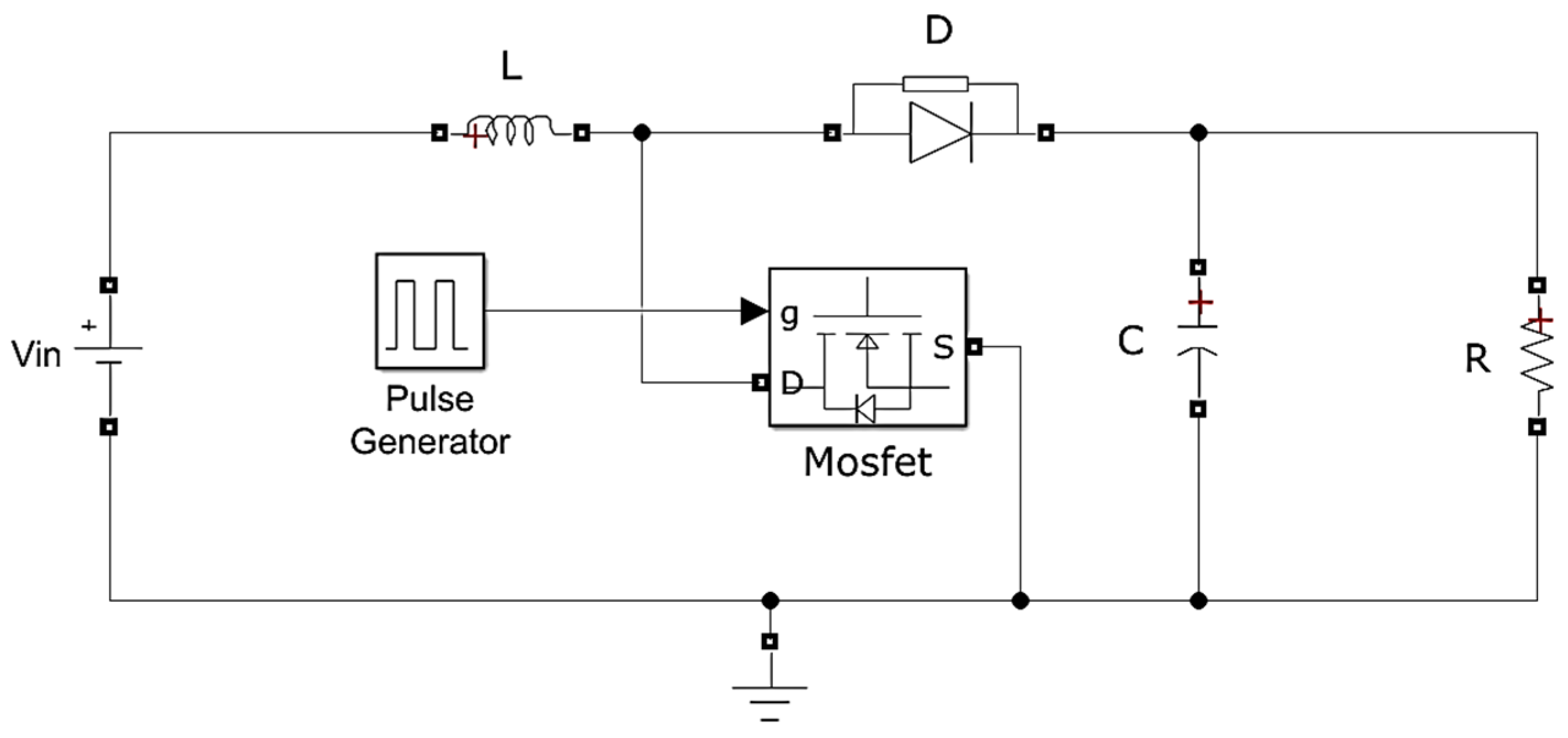
The boost converter is employed to step up the input source voltage, v i n , to a regulated value suitable for DC microgrid applications [40]. The circuit schematic of a conventional boost converter is depicted in Figure 1. The converter operates in Continuous Conduction Mode (CCM), in which its configuration alternates as the switching transistor (MOSFET) turns on and off during each switching cycle [41]. The output voltage, v o , is regulated by dynamically adjusting the duty cycle d applied to the transistor’s gate. The steady-state voltage conversion ratio is expressed in (1):
v o = 1 1 d v i n
s u c h   t h a t                     d = T O N T O N + T O F F
where T O N and T O F F denote the transistor’s on and off durations, respectively. A feedback controller adaptively modulates the duty cycle to ensure accurate tracking of the reference output voltage despite load variations and input fluctuations.
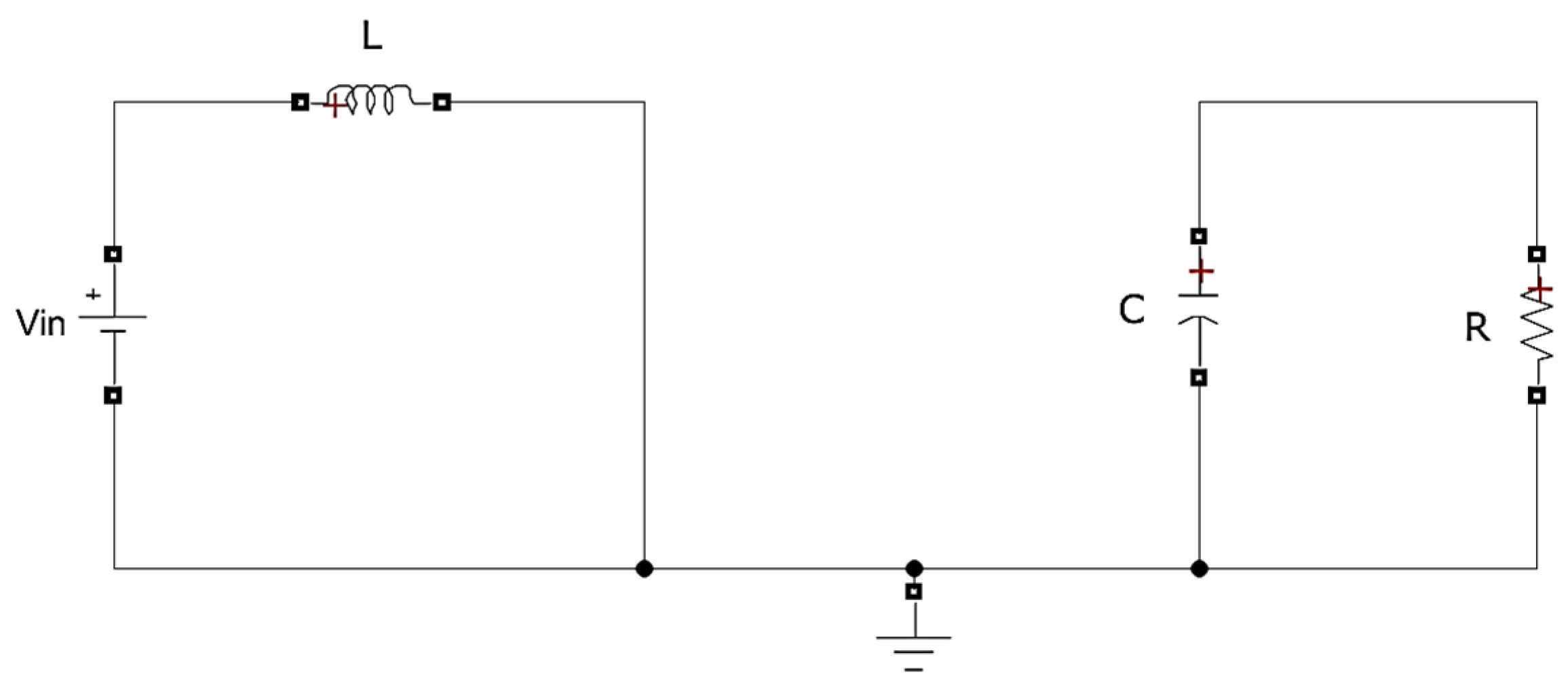
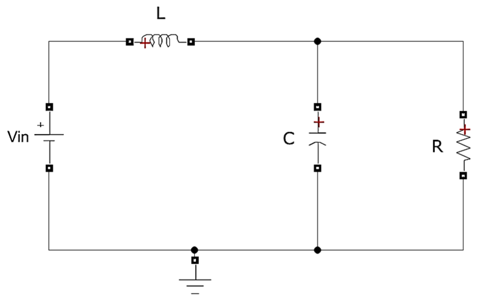
The input inductor L mitigates abrupt variations in v i n , while a sufficiently large output capacitor C maintains a time constant greater than the switching period for effective voltage smoothing. The activation of the MOSFET reverse-biases the diode and decouples the inductor from the output stage, as shown in Figure 2. During this cycle, the inductor stores energy while the capacitor supplies energy to the load. Conversely, the deactivation of the MOSFET forward-biases the diode, which couples the inductor to the output, as shown in Figure 3. The inductor’s polarity reverses, and its stored energy, together with the input source, charges the capacitor and feeds the load until the next switching cycle begins.

2.1. Dynamic Modeling

The boost converter is modeled using the state-space averaging technique under CCM [42]. The inductor current i L t and output (capacitor) voltage v o t are selected as the system’s state variables, while the duty cycle d t [ 0 , 1 ] serves as the control input. Considering the following two switching intervals [43].
When the MOSFET is on, the inductor stores energy from the input source, while the diode is open-circuit, and the capacitor supplies energy to the load. This behavior is represented via the following differential equations:
d i L t d t = v i n L ,     d v o t d t = v o t R C .
When the MOSFET is off, the inductor releases energy to the output stage through the diode. This behavior is represented via the following differential equations:
d i L t d t = v i n v o t L ,     d v o t d t = i L t C v o t R C .
Averaging the above dynamics over one switching period using the nominal value of the duty-cycle ratio D , the averaged model is obtained as expressed in (4) [43]:
d i L t d t = v i n L 1 D v o t L ,     d v o t d t = 1 D i L t C v o t R C .
The linear state space model of a system is represented as shown in (5):
x ˙ t = A   x t + B   u t ,     y t = C   x t + D   u t .
Defining the state vector of the system as x t = i L t v o t T and its output as y t , the converter’s state space model is expressed as shown in (6) [42]:
x ˙ t = 0 1 D L 1 D C 1 R C x t + 1 L 0   v i n y t = 1 0 0 1 x t
For control-oriented analysis, the converter’s averaged state-space model is linearized to explicitly incorporate the effect of duty-cycle variations d t . The linearization is performed about a steady-state operating point defined by ( D ,   v i n ). Using the first-order Taylor series expansion, the sensitivity of the state dynamics to duty-cycle perturbations is obtained by computing the following partial derivative [40]:
x ˙ t D = v i n L 1 D v i n R C 1 D 2 .
The generalized small-signal state equation can be represented as shown in (8) [40]:
x ˙ t = A   x t + x ˙ t D   d t + F v i n .
Since the duty-cycle perturbation constitutes the control input, we define the input signal and input vector as, u t = d t and B = x ˙ t D . Thus, the refined linearized state-space model assumes the standard control form as follows:
x ˙ t = A   x t + B   u t + F v i n .
The system’s state space matrices are given as follows:
A = 0 1 D L 1 D C 1 R C ,     B = v i n L 1 D v i n R C 1 D 2 ,     F = 1 L 0 .
The refined model captures the boost converter’s bilinear dynamics and serves as the foundation for subsequent controller synthesis, including the baseline LQR design and the proposed LQR-driven SMC framework for robust output voltage regulation. The model parameters used in this study are quantified in Table 1.

2.2. Baseline LQR Synthesis

The LQR is an optimal control technique that yields optimal control decisions as per the selection of the penalty matrices [44]. The LQR law is synthesized by minimizing a Quadratic-Performance-Index (QPI) defined over the state and control variables. The optimal solution is obtained by solving the Hamilton–Jacobi–Bellman (HJB) equation offline [45]. The QPI employed in this work is expressed as shown in (11):
J l q = 1 2 0 ( x t T Q x t + u t T R u ( t ) ) d t  
where R   ℝ represents a positive-definite control-penalty scalar and Q   2×2 represents a positive semi-definite state-penalty matrix. The matrix Q penalizes deviations in the converter states ( i L t and v o t ), while R constrains excessive duty-cycle variations. The penalty matrices are symbolically shown in (12):
Q = d i a g q i q v T ,             R = m  
where q i , q v 0 and m > 0 are weighting coefficients tuned offline, as discussed in Section 4. The optimal state compensator gain vector is computed by solving the Algebraic Riccati Equation (ARE) expressed in (13):
A T P + P A P B R 1 B T P + Q = 0
where P   2×2 is the ARE’s positive-definite symmetric solution matrix. The state compensator gains are obtained as shown in (14):
K = R 1 B T P
where K = k i k v . The nominal LQR law governing the boost converter’s duty cycle is therefore given by (15):
d l q t = K x t
where d l q t represents the optimal duty-cycle control input.
Stability Analysis: The closed-loop stability of the LQR-controlled boost converter is examined using the quadratic Lyapunov function shown below [45]:
W t = x t T   P   x t ,           W t > 0   x t 0 .
Differentiating the Lyapunov function yields the following expression(s):
W ˙ t = 2 x t T P x ˙ t = 2 x t T P A B K x t .
Substituting K = R 1 B T P and rearranging the final expression derived above yields the following expression:
W ˙ t = x t T P A + A T P x t 2 x t T P B R 1 B T P x t .
Using the ARE in (13), the derivative expression above simplifies to the following expression:
W ˙ t = x t T Q x t x t T P B R 1 B T P x t             < 0 .
Since R = R T > 0 and Q = Q T 0 , the Lyapunov candidate function’s derivative is always negative-definite, thereby guaranteeing the system’s closed-loop stability under the synthesized LQR control law.

3. Proposed Control Methodology

Following the synthesis of the optimal control framework, the controller is augmented with a discontinuous sliding mode component to enhance robustness against load uncertainties and input disturbances [46]. While the nominal LQR law guarantees asymptotic stability and optimal performance for the boost converter model, it lacks resilience to exogenous perturbations. To overcome this limitation, a composite control structure is formulated.

3.1. Composite LQR-Driven SMC Law

Let the uncertain plant dynamics be represented as expressed in (20) [46]:
x ˙ t = A   x t + B   u t + φ x , t
where φ x , t denotes lumped matched uncertainties and input disturbances. These uncertainties are assumed to satisfy the following matching condition [46,47]:
φ x , t = B   d r
where d r representing a bounded disturbance of known upper limit. The overall control input is decomposed as shown below [47]:
d t = d l q t + d s m t
where d l q t is the nominal LQR control action and d s m t is the discontinuous sliding mode term. Substituting this composite input into the plant dynamics yields the expression in (23):
x ˙ t = A   x t + B   d l q t + B   d s m t + B   d r .
The sliding manifold for the SMC is defined as expressed below [46]:
s t = G   x t + z t
where G is a design matrix and z t is an auxiliary function introduced to eliminate the conventional reachability phase. Enforcing the sliding condition s t = s ˙ t = 0 , and substituting the system dynamics, yield the expression in (25):
s ˙ t = G   x ˙ t + z ˙ t .
This expression is expanded as shown below:
s ˙ t = G A   x t + B   d l q t + B   d s m t + B   d r + z ˙ t .
To ensure a sliding motion from the initial instant, z t is selected as follows:
z ˙ t = G A   x t + B   d l q t ,     z 0 = G x 0 .
This choice simplifies the sliding dynamics to the expression shown below [46]:
s ˙ t = G B   d s m t + G B   d r .
Thus, during ideal sliding motion, the equivalent control compensates for the disturbance as shown below [46]:
d s m , e q t = d r .
The closed-loop system reduces to the nominal LQR-governed dynamics, ensuring disturbance rejection. The resulting sliding surface that removes the reachability phase is given by (30) [47]:
s t = G x t x 0 0 t A   x τ + B   d l q τ d τ .
To mitigate unmatched disturbances, the design matrix is commonly selected as the left pseudo-inverse of B [46]:
G = B + = B T B 1 B .

3.1.1. Stability Analysis

To establish closed-loop stability, consider the Lyapunov candidate in (32) [46]:
V t = 1 2 s T t   s t         >       0 .
This Lyapunov function’s time derivative is presented as follows:
V ˙ t = s T t   s ˙ t .
Substituting the sliding dynamics provides the function below:
V ˙ t = s T t   G B   d s m t + s T t   G B   d r .
The discontinuous control law is chosen as expressed below [46,47]:
d s m t = α sgn ( s t )
where α > 0 is the modulation gain, and sgn . represents the signum function of the following form:
s g n s t = 1 ,                                               i f     s t < 0 0 ,                                                     i f     s t = 0 1 ,                                                     i f     s t > 0 .
Substituting the discontinuous control law in V ˙ t yields the following expression:
V ˙ t = s T t G B α sgn s t + s T t G B d r .
The definition G = B + implies that G B = I , where I is an identity matrix [46]. The expression above reduces as shown below:
V ˙ t = α s t + s T t d r .
Bounding the disturbance term leads to the following function:
V ˙ t s t α + d r .
Hence, the Lyapunov stability condition V ˙ t < 0 is satisfied if α d r . This condition guarantees the existence of sliding motion and ensures the system’s closed-loop stability.
It is to be noted that the selection G = B + (left pseudo-inverse) implies G B = I , provided that the input matrix B has full column rank. For the linearized boost converter operating in CCM and within the admissible duty-cycle range 0 < d t < 1 , the input matrix B   2×1 remains nonzero and full column rank, ensuring B + B = I . The proposed stability analysis, therefore, holds for practical operating points away from duty-cycle saturation limits, where the averaged model remains valid.

3.1.2. Control Law Synthesis

The hybrid LQR-driven SMC law is formulated as shown in (40):
d t = K x t α sgn s t .
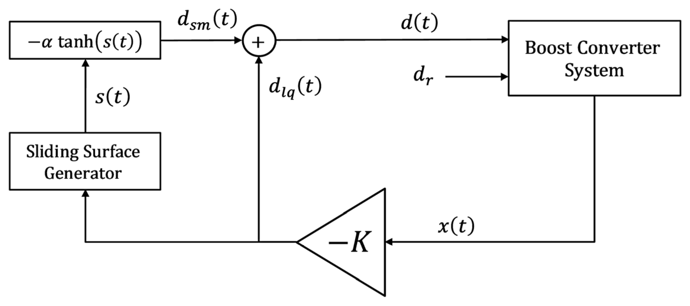
This composite strategy is hereafter denoted as the LQ–SMC scheme. To mitigate chattering induced by the discontinuous hard-limiting action of the signum function, sgn s t , is replaced by a Hyperbolic Tangent Function (HTF) [48]. The HTF is preferred due to its smooth, odd-symmetric nonlinear profile bounded within the interval [−1, +1]. The HTF also satisfies the same directional property as the signum function. For sufficiently large s t , the HTF can be represented as tanh s t sgn s t , thereby preserving the classical reaching condition and ensuring negative definiteness of the Lyapunov derivative outside a thin boundary layer, as described in (39). Near the origin, tanh s t s t , yielding V ˙ t = α s t 2 + s T t d r , which ensures boundedness and practical (quasi-)sliding motion. The discontinuity is replaced by a smooth boundary layer around s t = 0 , resulting in a small steady-state residual but preserving negative definiteness of V ˙ t outside that layer. Thus, substituting the signum function with the HTF preserves stability guarantees in the practical sense while significantly reducing chattering. Accordingly, the composite control law is modified and represented in (41) [47]:
d t = K x t α tanh s t
where tanh . represents the HTF. This modification retains the robustness characteristics of the sliding mode component while producing a continuous control signal better suited for practical power-electronic implementation. The corresponding control architecture is illustrated in Figure 4.
It is emphasized that the boost converter model remains unchanged throughout the analysis. The proposed controller is formulated as a composite law d t = d l q t + d s m t , where both components are synthesized using the same two-state averaged state-space representation. The LQR term provides nominal optimal stabilization, while the sliding-mode term enhances robustness against disturbances and parametric uncertainties. Hence, the plant model is unified, and the distinction lies solely in the control structure rather than in the system dynamics.

3.2. LQR-Based Self-Regulating SMC Law

The sliding-mode component of the composite control law is primarily activated in response to external disturbances [46,47]. However, the control law in (41) is augmented with an error-dependent adaptation mechanism that enhances its disturbance responsiveness by dynamically modulating the variation rate of the HTF.
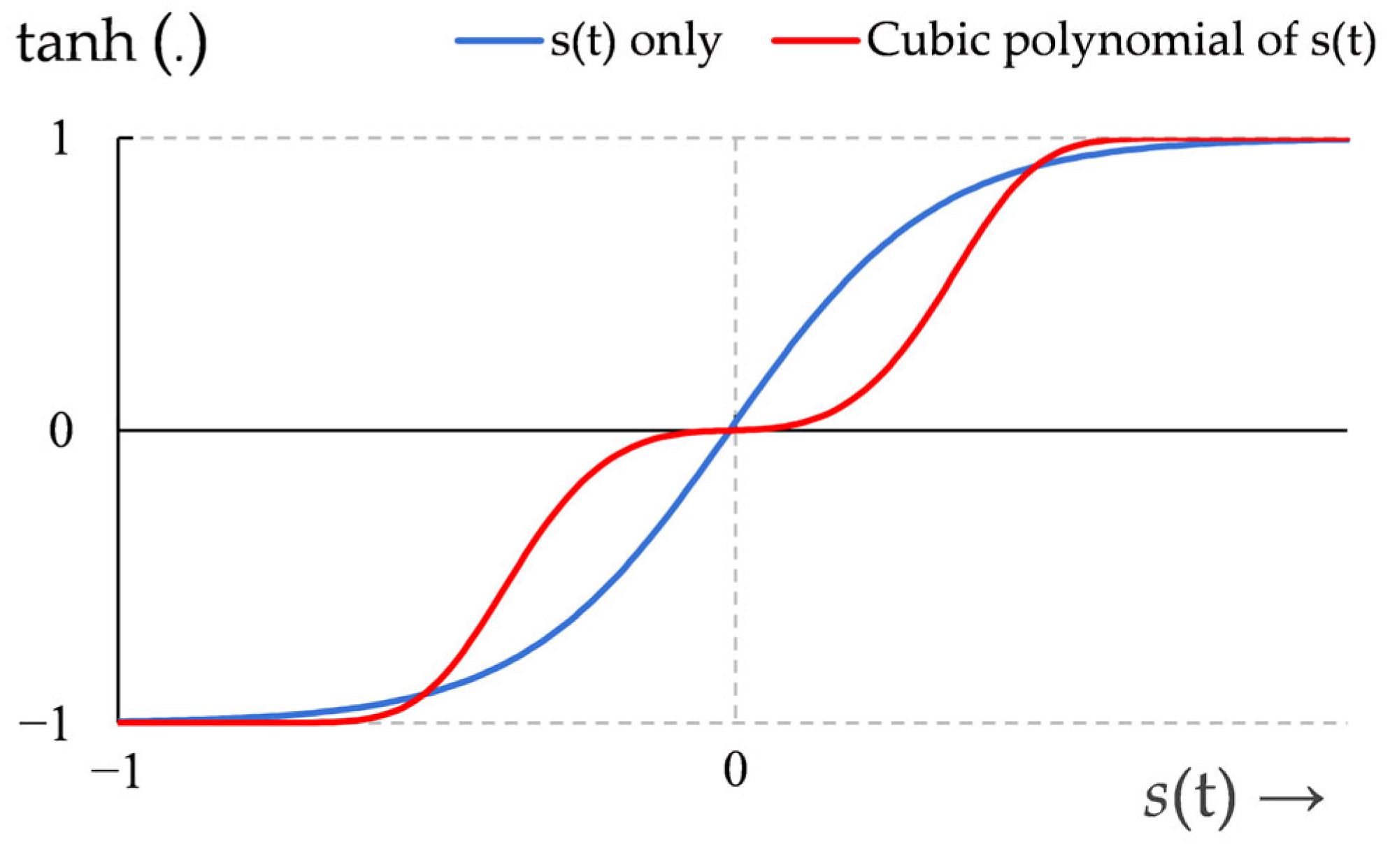
Instead of employing the sliding variable s t directly as the driving argument of the HTF, an odd cubic polynomial of the form s t + γ s t 3 is utilized [49]. The inclusion of this cubic polynomial generates distinct amplified and suppressed error zones, thereby producing a sharper increase in the discontinuous control magnitude under large voltage-regulation errors and a moderated response near equilibrium [50]. The waveform of the HTF, depending on the odd cubic polynomial of s t is illustrated in Figure 5.
The self-regulating composite control law is therefore represented as shown in (42):
u t = K x t α tanh m t s t + γ s t 3
where the parameter γ > 0 is tuned offline by using the methodology discussed in Section 4.
The time-varying variation rate of HTF’s waveform m t is adjusted online according to the following adaptation law:
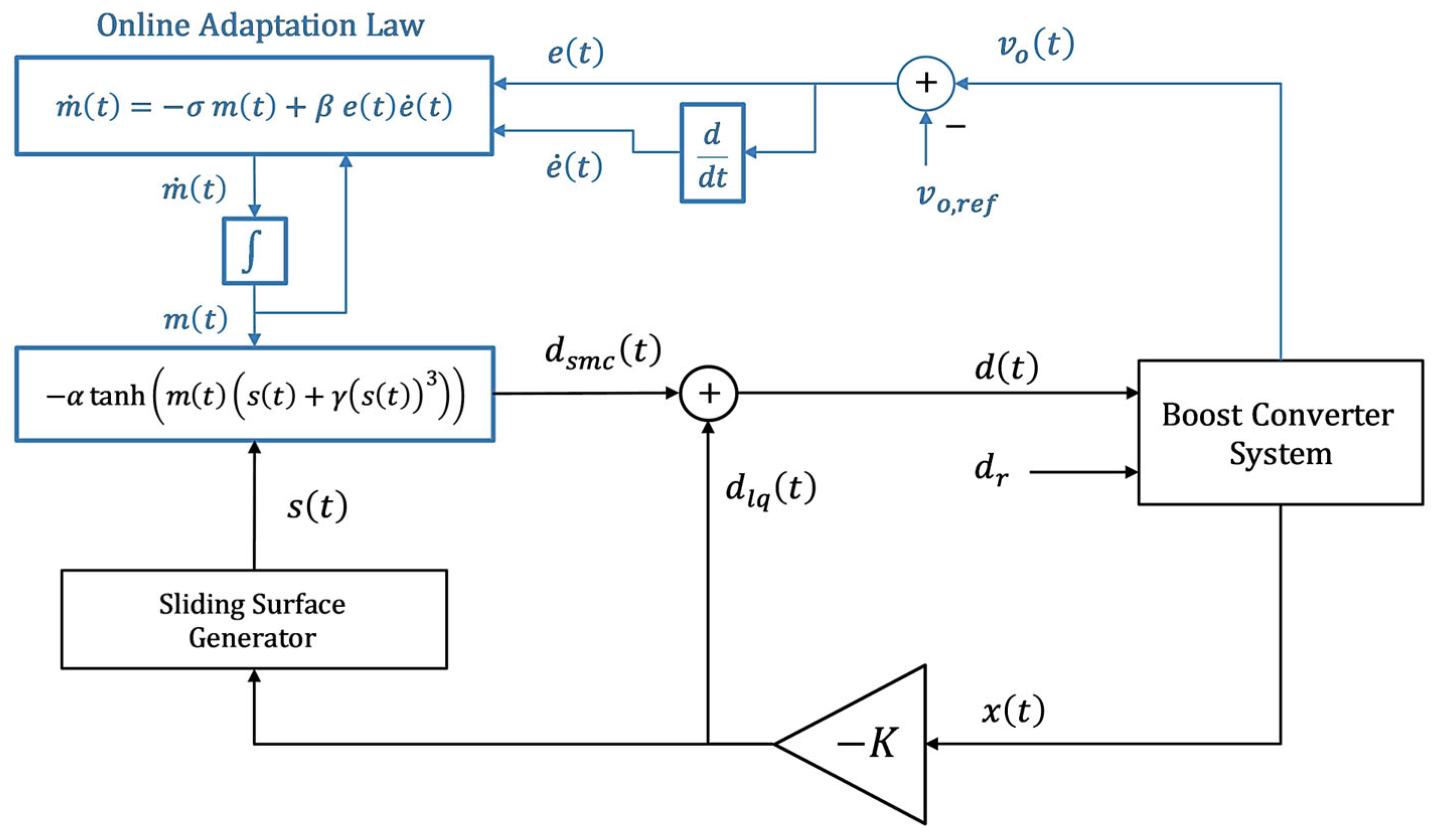
m ˙ t = σ   m t + β   e t e ˙ t
s u c h   t h a t ,                 e t = v r e f v o t .
where e t represents the voltage-regulation error between the converter’s actual output voltage and the desired reference voltage, v r e f , and σ > 0 and β > 0 denote the predetermined decay and adaptation rates, respectively. These coefficients are heuristically selected by using the technique outlined in Section 4.
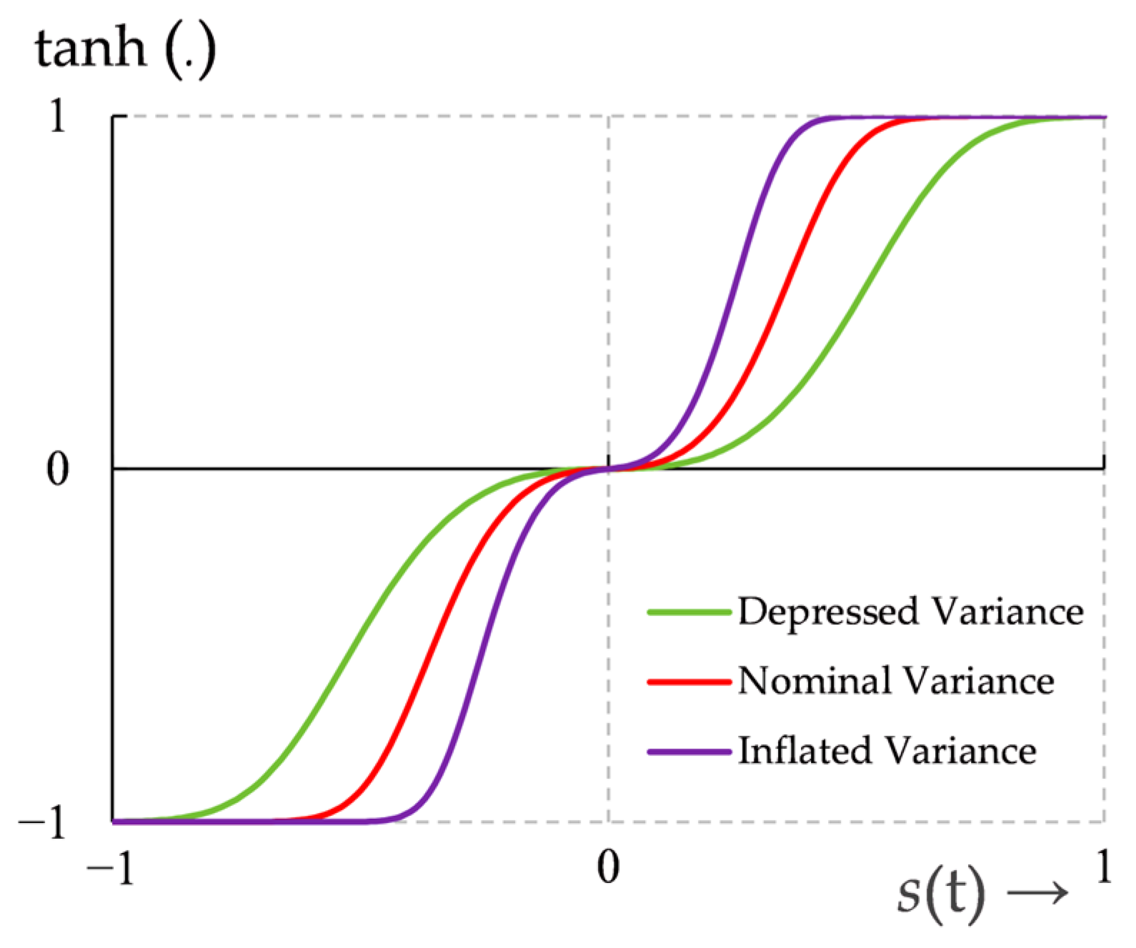
The proposed adaptation law comprises a dissipative component, σ   m t , and an anti-dissipative component, β e t e ˙ t [51]. The anti-dissipative term increases the variation rate when the tracking error diverges (since e t e ˙ t > 0 ), thereby strengthening the control effort during disturbance transients. Conversely, the dissipative term exponentially attenuates the HTF’s variation rate as the system approaches steady state, yielding a smoother control action. Through this dynamic variance inflation—depression mechanism, the controller is effectively reconfigured after each sampling interval, producing an aggressive control response for rapid disturbance rejection and a softened effort near equilibrium to enhance regulation accuracy while suppressing chattering [51]. The dynamic adjustment in the variation rate of the HTF waveform, as rendered by the proposed adaptation law, is illustrated in Figure 6. The numerical integration of the adaptation law, performed after each sampling instant for real-time implementation, is expressed in (44):
m t = e σ t   m 0 + 0 t e σ t p   β   e p e ˙ p   d p
where m 0 is set to unity. As long as the exponent term, σ t , remains negative definite in the adaptation law, the expression e σ t asymptotically decays toward zero as time progresses. The adaptation law m ˙ t constitutes a stable, first-order, linear system with bounded excitation. Since the closed-loop tracking error and its derivative are bounded, m t is also uniformly bounded. Empirical evaluation indicates that m = 20 produces a near-ideal signum-like switching response for very large magnitudes of the sliding variable s t in the considered application. Hence, in this study, m t is restricted within the limits of 0 to 20 via a saturation function of the form, 20   s a t m t , to ensure robustness against measurement noise and fast transients. The saturation function is described as follows:
20   s a t m t = 20 ,                                                   m t > 20 m t ,                           0 m t 20   0 ,                                                       m t < 0   .
Because the switching term employs a bounded HTF (Refer to (42)), the overall control input remains inherently bounded. The architecture of the LQ-driven Self-Regulating SMC (LQ-SRSMC) scheme is demonstrated in Figure 7.
In practice, the upper bound of the lumped matched disturbance d r is conservatively estimated using worst-case analysis of the converter’s operating envelope. The bound is derived from maximum expected input-voltage fluctuations, maximum load variation (e.g., ±50% step as used in simulations), component tolerances (e.g., ±10% for L , C , and R ), and parasitic effects, such as diode forward drop and MOSFET R o n . Using the small-signal linearized averaged model, parameter sensitivities are aggregated to ensure d r d m a x . This is a practicable approach in power-electronic SMC design. As discussed in Section 3.1.1, sliding-mode stability requires α d m a x . If the bound is slightly underestimated, the SMC formulation eliminates the reachability phase and the LQR guarantees asymptotic stability. Moreover, the proposed adaptive mechanism increases the variation rate of the HTF as the tracking error grows, effectively amplifying the switching intensity and compensating for moderate mismatch. If the bound is overestimated, the dissipative adaptation term softens the control near equilibrium, preventing excessive chattering. Although classical SMC guarantees invariance only for matched disturbances, the most dominant uncertainties in duty-cycle–modulated boost converters are effectively matched. The residual unmatched effects are mitigated by the proposed hybrid LQ-SRSMC structure, ensuring closed-loop stability and improved tolerance to practical parametric drift.

4. Parameter Tuning Scheme

The formulation of LQR based on the cost function J l q inherently depends on variations in the system’s states and control signal. However, optimal control decisions can only be achieved by appropriately weighting these variables. In practice, empirical tuning of Q and R matrices are often guided by limited engineering intuition. Similarly, the empirical selection of the parameters ( α , γ , σ , and β ) associated with the LQ-SMC and LQ-SRSMC is also constrained by the designer’s experience. Consequently, precise reference-tracking and fast transient recovery may not always be guaranteed.
To overcome this limitation, the prescribed parameters are selected offline by minimizing an auxiliary objective function that captures variations in e t and u t , expressed as follows:
J 2 = 0 e t 2 + u t 2 d t   .
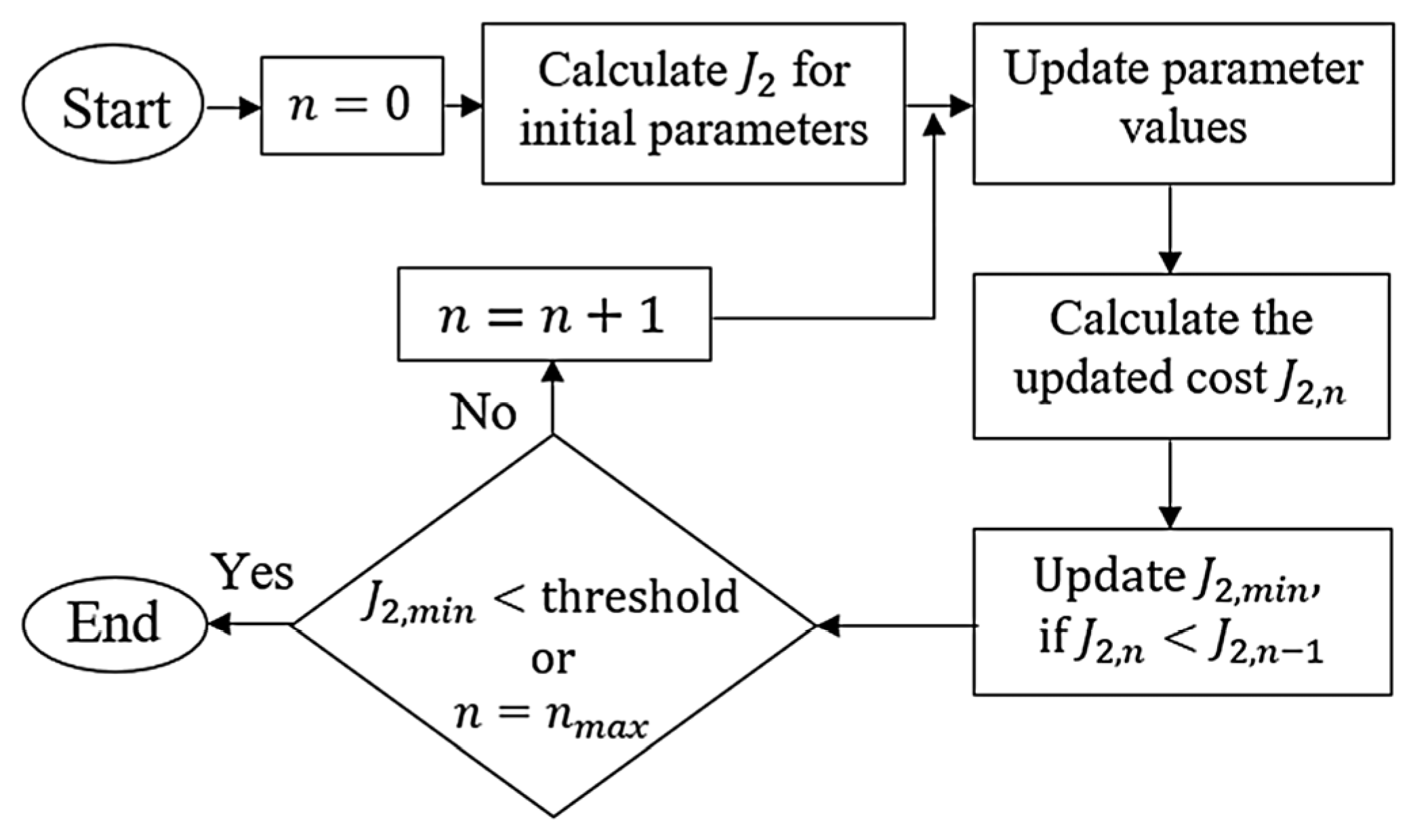
Equal weighting is assigned to both minimization criteria to ensure balanced optimization. The offline tuning method employs a coordinate-descent search with monotonic cost acceptance. Initial parameter values are randomly selected within the defined search space, and the algorithm iteratively explores the descending gradient of J 2 [34]. The tuning procedure is illustrated in Figure 8 [34]. In each trial, controller parameters are incrementally adjusted and applied to regulate the converter’s output voltage to 30.0 V over 1.0 s. It is to be noted that each parameter is incremented sequentially with a fixed step size (10% of its admissible range). The resulting cost J 2 , n is then evaluated. If J 2 , n < J 2 , n 1 , the local minimum J 2 , m i n is updated, ensuring descent along the cost gradient. The search terminates when either J 2 , m i n reaches the predefined threshold or the maximum number of trials ( n m a x ) is completed [34]. In this study, J 2 , m i n is set to 1 × 10 4 and n m a x = 30 due to the high simulation time. Final parameter values are further fine-tuned manually. Multiple random initializations yielded less than 5% variation in final cost, indicating low sensitivity to initial conditions.
For baseline LQR design, the coefficients of Q matrix and the R scalar are chosen from [0, 500] and [0, 1], respectively. The coefficients of these matrices are initialized at unity. The optimized weights are Q = d i a g 146.6 155.8 T ,   R = 0.9 . Using these matrices, the LQR gain vector is obtained as K = 13.25 3.16 .
For the LQ-SMC design, the switching gain α d r is initialized to unity and is chosen from the range [0, 10]. Considering a disturbance signal d r = 5 , the optimized value of α = 5.25 .
For the LQ-SRSMC scheme, the HTF variation rate parameters ( γ , σ , and β ) are tuned within the range [0, 10], starting from unity and converging to γ = 1.55 , σ = 1.08 , and β = 2.17 .

5. Simulations and Performance Evaluation

This section presents the simulation framework and results used to assess the responsiveness of the prescribed LQ-SRSMC controller, benchmarked against the LQR and the LQ-SMC procedure under various disturbances.

5.1. Simulation Setup

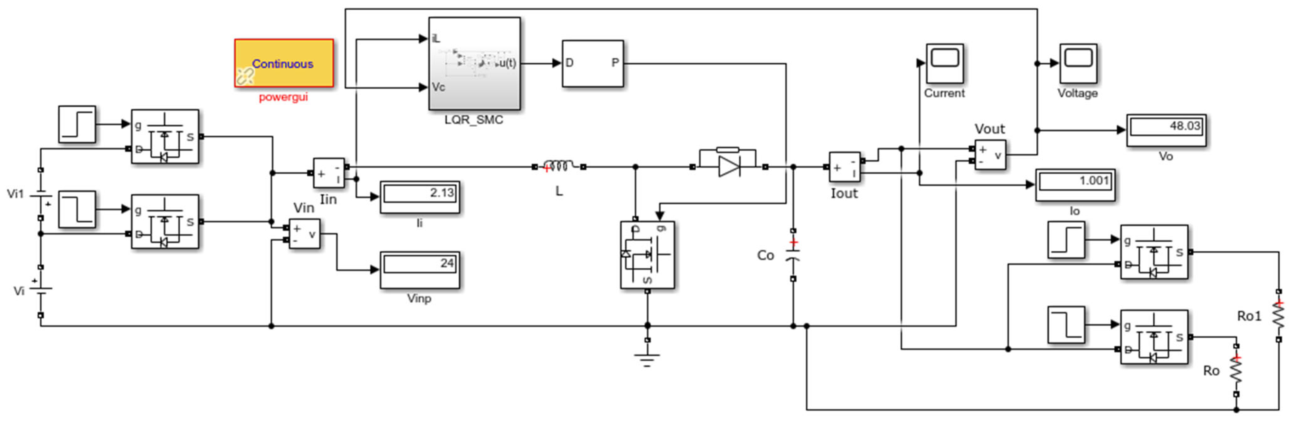
The regulatory control behavior of the prescribed LQ-SRSMC controller was evaluated via customized time-domain simulations of the DC–DC boost converter model. All simulations were performed in MATLAB/Simulink R2020b on a 64-bit workstation equipped with a 2.4 GHz Intel Core i7 processor and 12.0 GB RAM. The converter’s state and control input variations were accurately captured at a sampling frequency of 1.0 kHz. The converter’s averaged state-space model, derived in Section 2, is implemented using nominal circuit parameters (listed in Table 1) to achieve a regulated step-up operation from 24.0 V input to 48.0 V output. The control block diagram implemented in Simulink is shown in Figure 9. A zero-mean band-limited white noise (power = 10−4) is superimposed on the v o feedback signal using Simulink’s band-limited white noise source block. This disturbance accounts for sensor noise, switching ripple remnants, and electromagnetic interference typically encountered in power electronic environments.
The converter is designed with a 24 V input voltage, a 48 V output voltage, and a 1 A output current. The converter operates at 90% efficiency with a switching frequency of 1.0 kHz, while maintaining an output voltage ripple of 20 mV. The designed controllers are tested under identical operating conditions to ensure a fair comparative assessment of voltage-regulation accuracy and transient recovery. Performance evaluation is conducted across multiple operating scenarios, including reference-voltage tracking, load-step transients, and input-voltage fluctuations. The effectiveness of each controller is quantified using overshoot, settling time, steady-state error, and transient-recovery time, thereby providing a comprehensive assessment of regulation performance and disturbance rejection capability.
Although the analysis is conducted using the averaged model, the controller is implemented in discrete time with zero-order hold at the PWM switching frequency. The switching frequency is selected to be at least one order of magnitude higher than the closed-loop bandwidth to ensure time-scale separation and negligible discretization-induced phase lag. Duty-cycle saturation in the range [0, 1] is explicitly included in the loop to guarantee bounded control action. Under these conditions, the discrete-time realization preserves stability and maintains performance comparable to the continuous-time design.

5.2. Simulations and Results

The comparative performance of the LQR, LQ-SMC, and LQ-SRSMC schemes is evaluated via four customized simulations designed to assess the system’s output regulation accuracy and disturbance resilience under practical operating conditions.
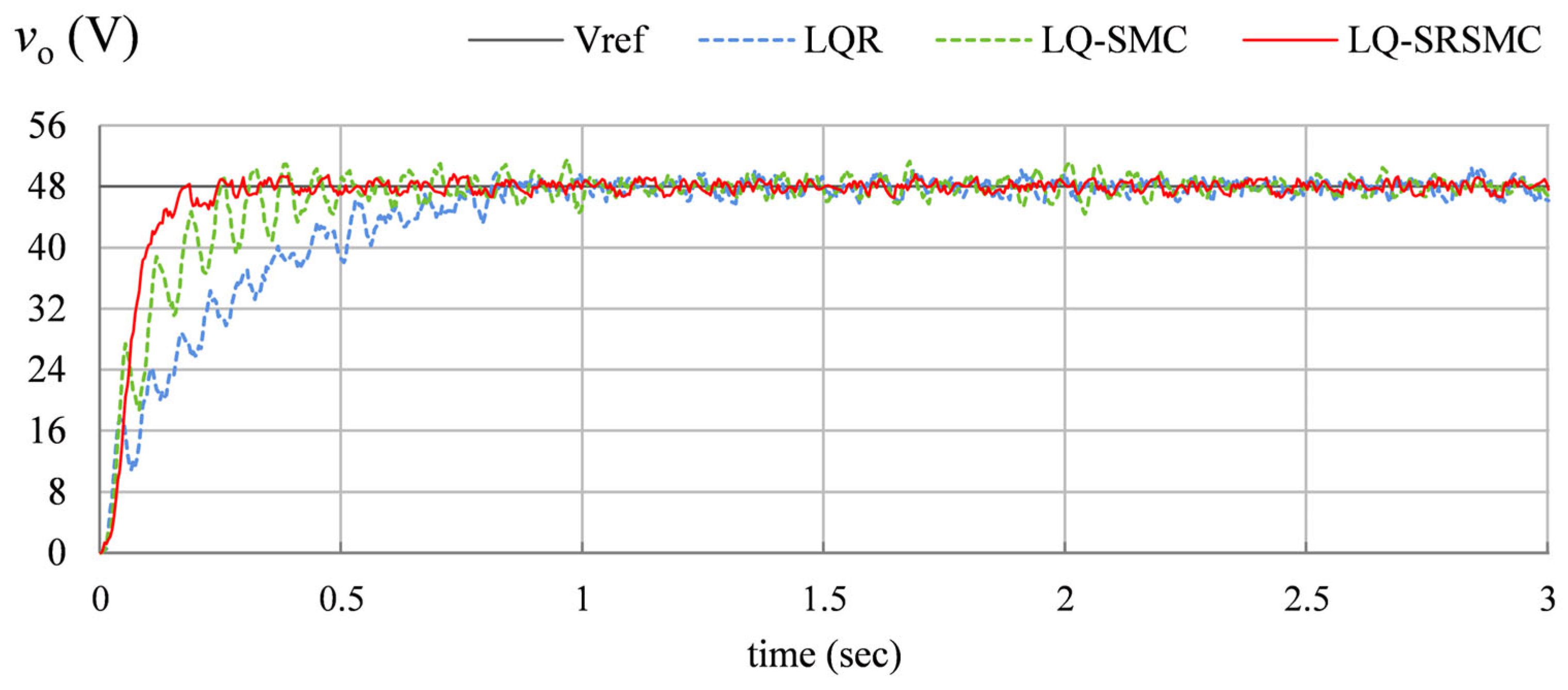
  • Nominal voltage regulation: This experiment examines transient response characteristics and reference-tracking accuracy under nominal operating conditions. Each controller is tasked with regulating the output voltage to a +48.0 V DC reference while maintaining constant input voltage and load resistance at +24.0 V and 10 Ω, respectively. The corresponding time-domain responses of the output voltage v o t for all controllers are presented in Figure 10.
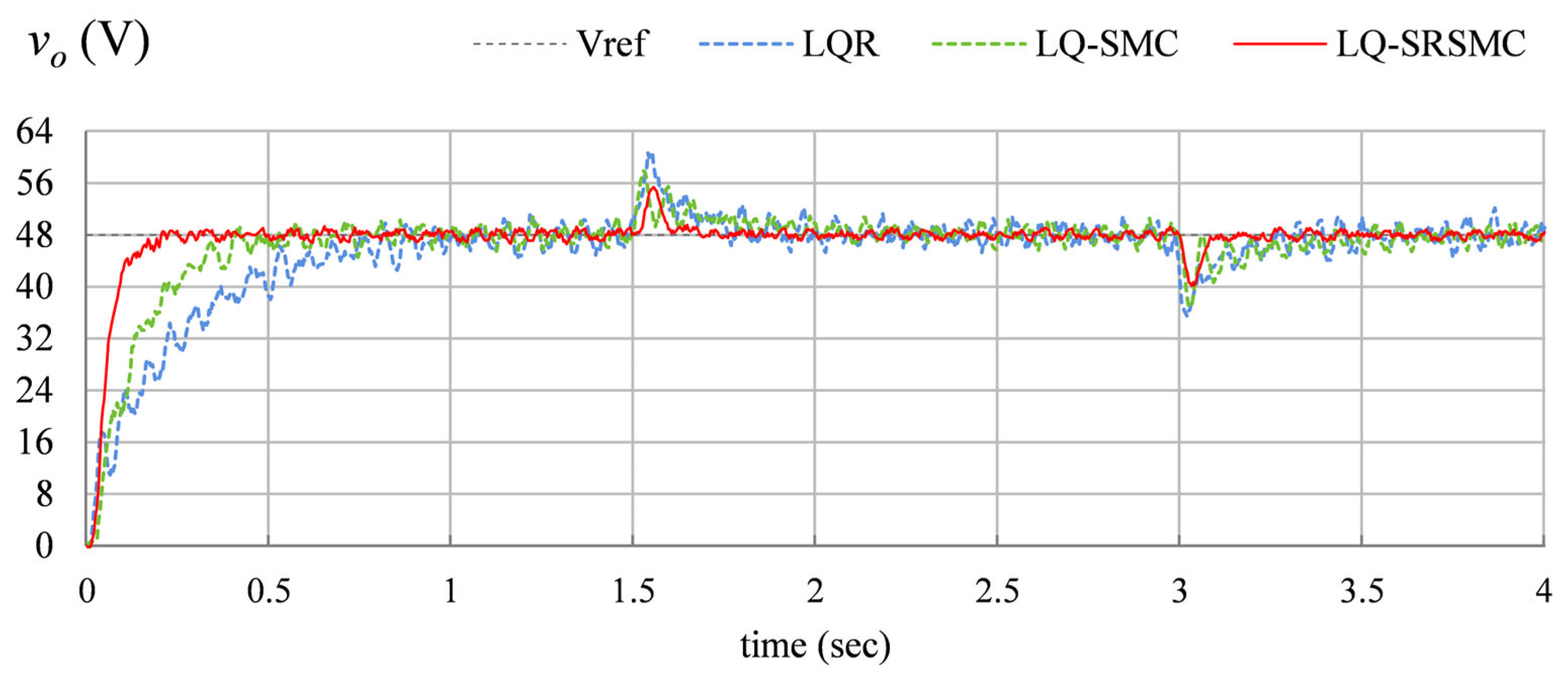
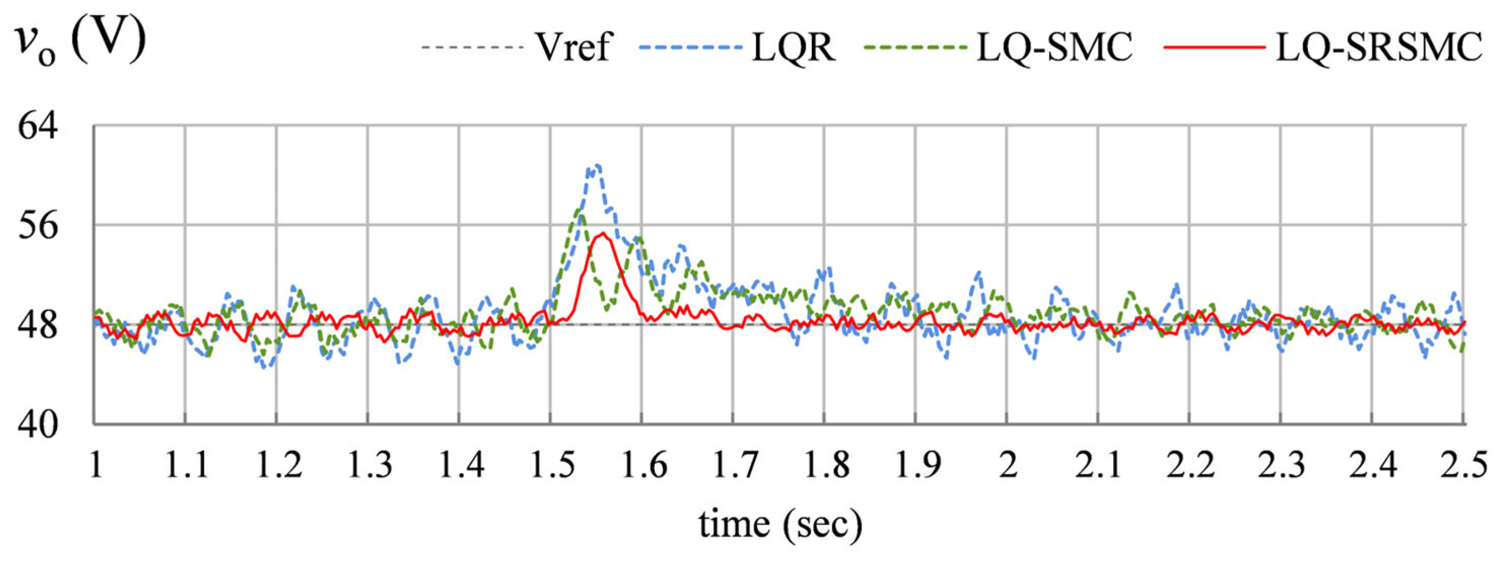
  • Load disturbance rejection: This test evaluates the controllers’ capability to suppress output-voltage deviations arising from sudden load variations. A 50% step reduction in load resistance is introduced at t = 1.5   s by activating the transistor switches connected with each load. Subsequently, the load is increased by deactivating the switch at t = 3.0   s . The induced perturbations in v o t and the corresponding recovery profiles are illustrated in Figure 11. A time-window magnification of the v o t response is presented in Figure 12 to emphasize disturbance-induced transients and recovery dynamics.
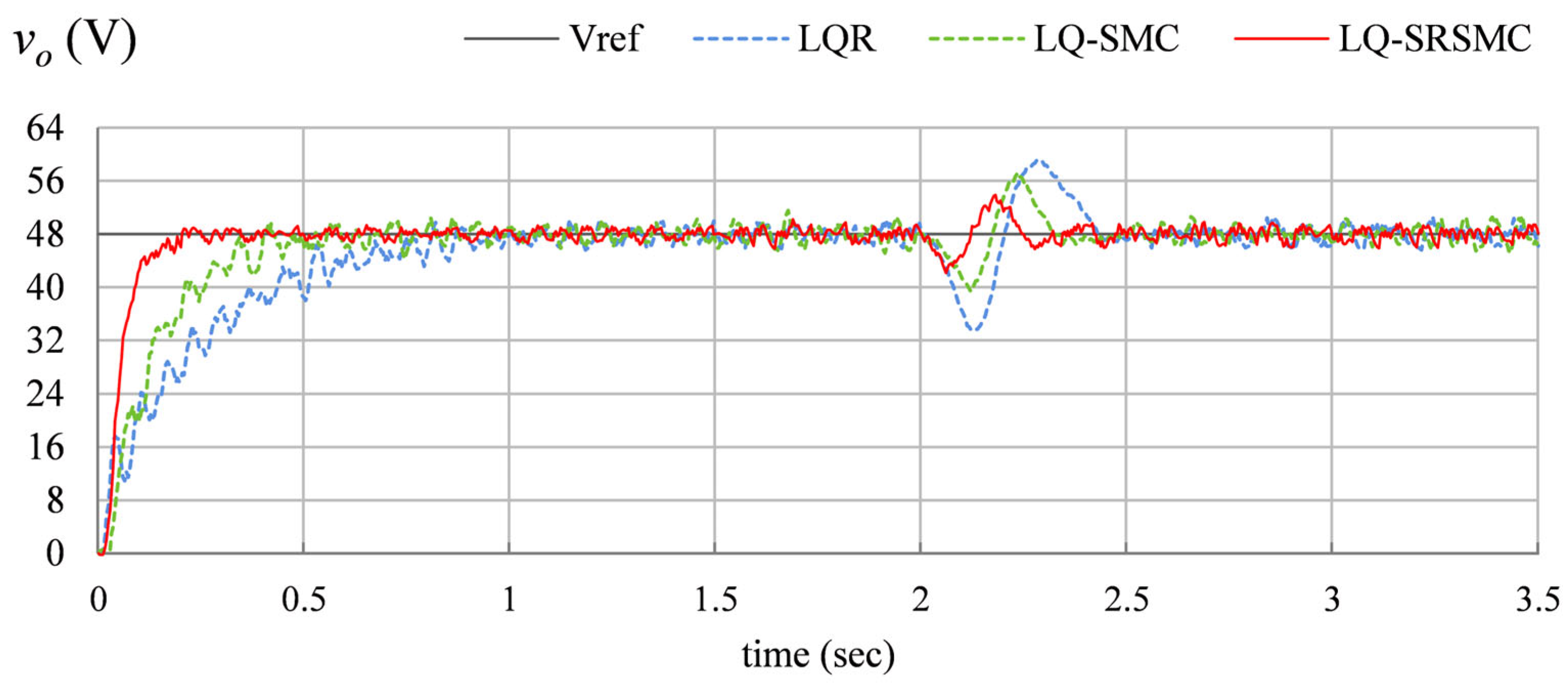
  • Source Disturbance Compensation: This simulation assesses the adaptability of each control scheme against input-voltage fluctuations. The respective switches, connected to the unregulated source voltages, are toggled at t = 2.0   s . to reduce the source voltage from +24.0 V to +12.0 V. The resulting disturbances in the output-voltage trajectory v o t are depicted in Figure 13.
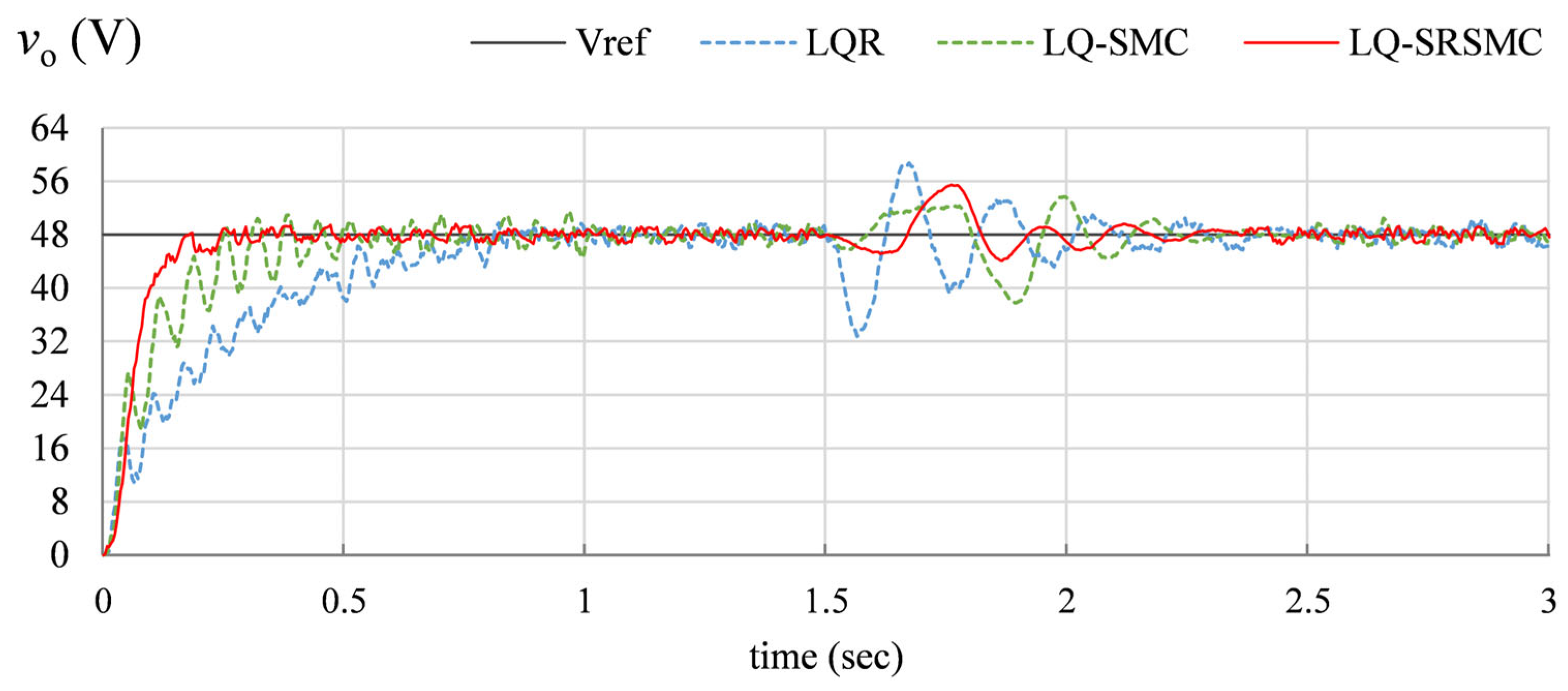
  • Multi-Disturbance Compensation: This simulation evaluates the controller’s robustness under simultaneous variations in source voltage and load impedance. These operating conditions are relevant to DC microgrid and EV-integration scenarios, emulating the impacts of renewable intermittency and load uncertainty. The test is conducted by simultaneously reducing the load resistance and the source voltage by 50% at t = 1.5   s . by toggling the respective switches. The resulting perturbations in v o t profile are depicted in Figure 14.

5.3. Discussion

The outcomes of the simulations are evaluated via the following standard Key Performance Indices (KPIs) relevant to DC–DC boost converter voltage regulation.
  • e r m s : Root-mean-square output voltage tracking error.
  • t r : Time required for v o to rise from 10% to 90% of v r e f .
  • t s : Settling time within ±2% of v r e f during startup.
  • O S : Startup peak overshoot in v o .
  • M p : Peak overshoot under load or input disturbances.
  • t r e c : Post-disturbance recovery time within ±2% of v r e f .
  • v p p : The maximum peak-to-peak voltage in the steady state response of v o .
  • T V d : Total variation of duty cycle that measures cumulative switching activity and indicates the degree of chattering and switching stress. It is evaluated as shown below:
    T V d = k = 1 N 1 d k + 1 d k .
These indices provide a comprehensive assessment of the boost converter’s time-domain voltage regulation performance. Table 2 summarizes the quantitative comparison of the prescribed LQ-SRSMC scheme against the conventional LQR and LQ-SMC schemes.
In Test A, the conventional LQR demonstrates the slowest transient recovery with observable steady-state oscillations under nominal conditions. LQR exhibits a moderate duty cycle variation. The introduction of the sliding term in the LQ–SMC scheme improves damping and reduces overshoot; however, reasonable chattering is introduced in the response. However, the higher value of T V d indicates stronger chattering and switching stress. The proposed LQ-SR-SMC strategy delivers the fastest reference tracking with superior suppression of startup oscillations. Its self-regulating nonlinear sliding action dynamically modulates the HTF’s variation rate, resulting in aggressive control during large transients and softened action near the steady state. The proposed controller also shows a lower value of T V d , indicating smoother duty modulation and reduced switching effort.
In Test A, compared with LQR, the proposed controller reduces e r m s by 40.3%, t s by 57.5%, O S by 21.7%, and v p p by 37.3%, and corresponding improvements of the proposed scheme over LQ-SMC are 20.9%, 35.4%, 54.4%, and 55.6%, respectively.
In Test B, step changes in load resistance R introduce modeling uncertainty that significantly deteriorates LQR performance, producing large voltage deviations and slow recovery. The LQ–SMC scheme improves robustness owing to its discontinuous switching, but it exhibits residual chattering and a moderate recovery speed. Also, the LQ-SMC has the highest switching activity due to discontinuous control. In contrast, the LQ-SRSMC controller adaptively reshapes the sliding control effort through its error-dependent self-regulating mechanism. This enables rapid suppression of load-induced perturbations, reduced peak overshoot M p , and faster restoration of the regulated output voltage, thereby demonstrating markedly enhanced disturbance rejection capability. The proposed LQ-SRSMC exhibits the lowest duty-cycle variation, indicating smoother control action and reduced switching effort. Performance gains of the proposed scheme over LQR include reductions of 37.9% in e r m s , 38.4% in M p , and 60.9% in t r e c . The improvement exhibited by the proposed scheme over LQ-SMC are 27.2%, 23.6%, and 41.9%, respectively.
In Test C, the input supply fluctuations induce abrupt perturbations in v o . The fixed-gain LQR controller shows limited adaptability, while the LQ–SMC scheme provides improved compensation at the expense of switching-induced ripple. The proposed LQ-SRSMC law exhibits the most resilient behavior. Its adaptive nonlinear sliding profile intensifies the corrective control effort during disturbance intervals and gradually relaxes it as the system approaches steady state. Moreover, the LQ-SRSMC yields the lowest duty cycle variation, confirming reduced chattering and switching stress. Relative to LQR, the proposed scheme reduces e r m s by 38.9%, v p p by 53.7%, and t r e c by 27.9%. Improvements shown by LQ-SRSMC over LQ-SMC are 28.4%, 34.2%, and 13.9%, respectively.
In Test D, the results demonstrate that the proposed LQ-SRSMC controller maintains stable voltage regulation and fast transient recovery across multiple disturbances, confirming robustness beyond the nominal test condition.
Overall, the proposed LQ-SRSMC scheme ensures precise output voltage regulation with superior robustness against load variations, input fluctuations, and modeling uncertainties. Its enhanced performance is attributed to the synergistic combination of optimal LQR state feedback with an adaptively self-modulated sliding-mode term. Although the sliding control law is derived using the discontinuous signum function, its practical implementation replaces sgn s t with a smooth hyperbolic tangent approximation tanh m t s t + γ s t 3 . This introduces a boundary layer around the sliding surface, resulting in quasi-sliding motion with bounded steady-state error while significantly mitigating chattering. The adaptive variation rate of the HTF waveform, m t , further regulates switching intensity, ensuring smooth control action without compromising robustness. In particular, the inclusion of the cubic nonlinear term improves the closed-loop system’s convergence for large deviations. Hence, unlike conventional LQ-SMC, the self-regulating mechanism dynamically adjusts the waveform of the nonlinear switching function in response to state-error phase variations, thereby mitigating chattering while preserving robustness. This results in a control effort that is aggressive under large disturbances and progressively softened near equilibrium, ensuring fast transient recovery alongside high steady-state accuracy.
While the LQ-SMC scheme requires prior knowledge of the disturbance bound d r for gain selection, the proposed LQ-SRSMC reduces dependence on an exact bound by effectively utilizing the adaptive nonlinear modulation of the switching term. The LQR component guarantees asymptotic stability, whereas the self-regulating mechanism increases the switching intensity as the tracking error increases. Therefore, the controller maintains bounded stability even when the disturbance bound is not precisely known, provided disturbances remain finite.

5.4. Comparison with a State-of-the-Art Controller

To further evaluate the effectiveness of the proposed controller, a comparison is performed with a state-of-the-art Power-Rate Sliding Mode Controller (PR-SMC). The PR-SMC employs Gao’s reaching law to enforce finite-time convergence of the sliding variable. The sliding mode controller drives the boost converter states toward a predefined sliding surface s t defined by the output-voltage tracking error. The sliding surface is defined as shown below:
s t = W T ε t
where ε t = x t x r e f , and W T = w 1 w 2 is the user-specified sliding surface gain vector. The reference state vector is represented as x r e f = 1.0 48.0 T . To ensure finite-time convergence of the sliding surface, Gao’s reaching law is adopted:
s ˙ t = ρ   s t δ   s g n s
where ρ > 0 is a positive reaching gain and 0 < δ < 1 is the power rate coefficient. Differentiating the sliding surface yields the following expression:
s ˙ t = W T ε ˙ t
w h e r e   ε ˙ t = x ˙ t x ˙ r e f .
Substituting the averaged boost converter model, x ˙ t = A   x t + B   u t , and assuming a constant reference, such that x ˙ r e f 0 0 T , the sliding dynamics become:
s ˙ t = W T A   x t + W T B   u t .
Equating (49) and (51) yields the following expression:
ρ   s t δ   s g n s = W T A   x t + W T B   u t .
Solving for the control input u t (duty cycle command) yields the PR-SMC law expressed in (53):
u t = W T B 1 W T A   x t + ρ   s t δ   s g n s .
The parameters ρ , δ , and the sliding surface gain vector are optimized offline using the technique discussed in Section 4. The sliding gains are selected as W T = 4.23 1.04 . The other parameter settings are ρ = 5.92 and δ = 0.62 .
To analyze the stability of the PR-SMC law, consider (once again) the following Lyapunov function:
Z t = 1 2 s T t   s t         >       0 .
This Lyapunov function’s time derivative is presented as follows:
Z ˙ t = s T t   s ˙ t .
Substituting the sliding dynamics in (51) provides the function below:
Z ˙ t = s T t   W T A   x t + W T B   u t .
Substituting the control law of (53) in (56) provides the following expression:
Z ˙ t = ρ   s t δ + 1 .
Since ρ > 0 , Z ˙ t < 0 , which guarantees finite-time convergence of the sliding surface and therefore ensures stable regulation of the boost converter output voltage. To minimize the chattering and switching stress, the s g n s in the (53) is replaced by the odd-symmetric HTF driven by the cubic power of s t . The final PR-SMC law is shown in (58):
u t = W T B 1 W T A   x t + ρ   s t δ t a n h s 3 t .
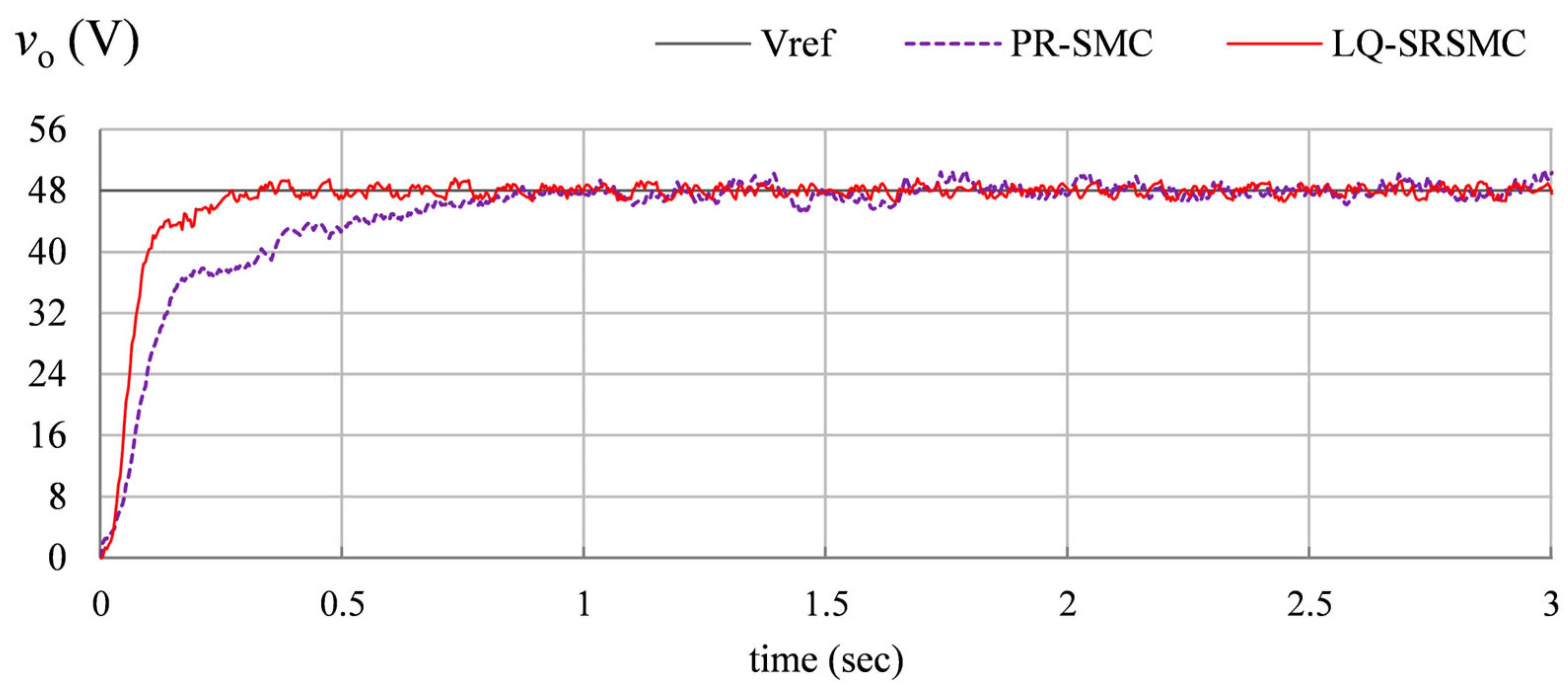
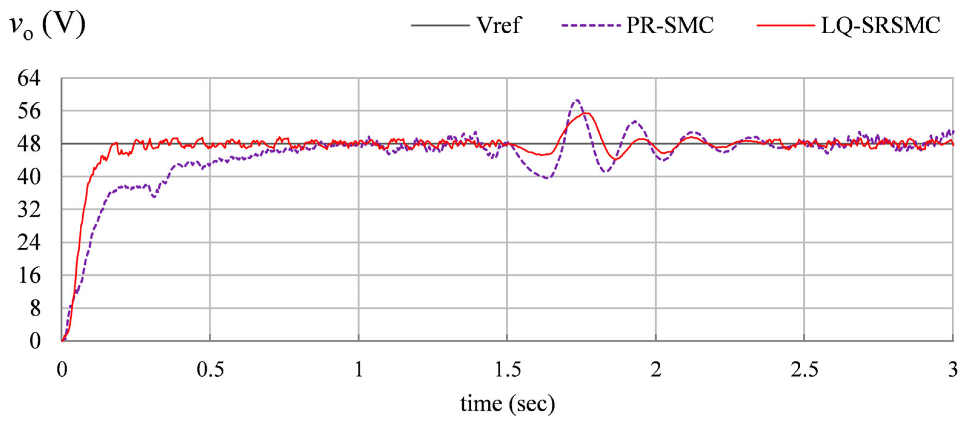
The performance comparison between the PR-SMC law and the proposed LQ-SRSMC law is conducted using the two evaluation scenarios considered in Section 5.2: nominal operating condition (Test A) and multiple disturbance scenario (Test D). The simulation results for these scenarios are depicted in Figure 15 and Figure 16, respectively.
The time-domain performance is evaluated using the same KPIs adopted throughout this study. The simulation results are summarized in Table 3. The results show that while the PR-SMC achieves moderate disturbance rejection, it introduces relatively higher duty-cycle fluctuations due to discontinuous switching. In contrast, the proposed controller achieves smoother duty-cycle modulation, reduced switching activity, and improved voltage regulation, particularly under multi-operating-point conditions. The results highlight the advantage of the LQ-SRSMC strategy in maintaining robust performance while reducing switching stress, making it more suitable for DC microgrid applications.
The proposed framework is structurally scalable. It can, therefore, be extended and applied to other DC–DC converter topologies and power electronic systems, provided their nominal state-space representations are available.

6. Conclusions

This paper presented a composite robust optimal control framework for output-voltage regulation of a boost converter using an LQ-SRSMC strategy. The proposed scheme synergistically integrates the optimal steady-state performance of LQR with the disturbance-rejection capability of SMC, while mitigating its inherent chattering. The baseline LQR law was augmented with a nonlinear sliding term whose switching profile was smoothed using an HTF. To further enhance adaptability, an error-dependent self-regulating adaptation mechanism was introduced to dynamically modulate the variation rate of the nonlinear sliding function in real time. This adaptive formulation enabled aggressive control action during large transients and softened control near steady state, thereby improving both robustness and regulation accuracy. Comprehensive simulations under nominal regulation, load-step transients, input perturbations, and modeling variations verified that the proposed LQ-SRSMC scheme outperforms conventional LQR and LQ-SMC strategies in terms of voltage regulation accuracy, transient recovery, and disturbance compensation, while maintaining smooth control effort suitable for practical power-electronic implementation.
Overall, the proposed control framework is computationally tractable and readily extendable to other DC–DC converter topologies and microgrid power conditioning applications that require robust high-performance voltage control. Future work can focus on real-time hardware validation to examine switching nonidealities and sensing constraints. Future work can also focus on transitioning this framework from simulation to Hardware-in-the-Loop (HIL) testing to validate its performance under real-time computational constraints. The framework can also be extended to coordinated control of multi-converter renewable-integrated DC microgrids for bus stabilization and power sharing. Additionally, other soft-computing techniques and machine-learning-enhanced self-regulation mechanisms can also be investigated to autonomously tune the hyperparameters of the control law under parametric variations and disturbance conditions.

Author Contributions

Conceptualization, O.S.; methodology, O.S.; software, O.S. and M.R.; validation, J.I.; formal analysis, O.S. and M.R.; investigation, O.S. and M.R.; resources, J.I.; data curation, M.R.; writing—original draft preparation, O.S. and M.R.; writing—review and editing, J.I.; visualization, J.I.; supervision, J.I.; project administration, J.I. The research has been conducted while the corresponding author was affiliated with AASU. All authors have read and agreed to the published version of the manuscript.

Funding

This research has not been funded by any internal or any external funding source.

Data Availability Statement

The original contributions presented in this study are included in the article. Further inquiries can be directed to the corresponding author.

Conflicts of Interest

The authors declare no conflicts of interest in preparing this article.

References

  1. Mariprasath, T.; Shivashimpiger, S.; Rivera, M.; Wheeler, P.; Reddy, M.P.P.; Ali, S.M.; Peruthambi, V.; Bonaldo, J. An experimental investigation of unique high step-up boost converter for electric vehicle and solar photovoltaic. Sci. Rep. 2026, 16, 2402. [Google Scholar] [CrossRef]
  2. Joseph, P.K.; Devaraj, E. Design of hybrid forward boost converter for renewable energy powered electric vehicle charging applications. IET Power Electron. 2019, 12, 2015–2021. [Google Scholar] [CrossRef]
  3. Divya, N.; Sathik, J.; Almakhles, D. A comprehensive study on various dc–dc converter voltage-boosting topologies and their applications. Circuit World 2022, 48, 529–549. [Google Scholar]
  4. Alfred, D.; Czarkowski, D.; Teng, J. Reinforcement Learning-Based Control of a Power Electronic Converter. Mathematics 2024, 12, 671. [Google Scholar] [CrossRef]
  5. Zeb, O.; Rehman, A.; Sultan, N.; Sherazi, H.I.; Alsafrani, A.; Akram, R. Robust nonlinear control of an isolated boost converter with voltage doubler for high-performance regulation and disturbance rejection. Energy Rep. 2026, 15, 109111. [Google Scholar] [CrossRef]
  6. Li, G.; He, J.; Liu, X. A DC Voltage Robust Control Strategy of Boost Converter Based on Load Impedance and Input Voltage Observation. IEEE Trans. Ind. Inform. 2024, 20, 7947–7956. [Google Scholar] [CrossRef]
  7. Serra, F.M.; Esteban, F.D.; Montoya, O.D. Control of DC-DC boost converter in discontinuous conduction mode feeding a constant power load. Results Eng. 2024, 23, 102732. [Google Scholar] [CrossRef]
  8. Ghosh, A.; Banerjee, S. A comparative performance study of a closed-loop boost converter with classical and advanced controllers using simulation and real-time experimentation. Int. Trans. Electr. Energy Syst. 2020, 30, e12537. [Google Scholar] [CrossRef]
  9. Kobaku, T.; Jeyasenthil, R.; Sahoo, S.; Ramchand, R.; Dragicevic, T. Quantitative feedback design-based robust PID control of voltage mode-controlled DC-DC boost converter. IEEE Trans. Circuits Syst. II Expr. Br. 2020, 68, 286–290. [Google Scholar] [CrossRef]
  10. Saleem, O.; Rizwan, M.; Khizar, A.; Ahmad, M. Augmentation of fractional-order PI controller with nonlinear error-modulator for enhancing robustness of DC-DC boost converters. J. Power Electron. 2019, 19, 835–845. [Google Scholar]
  11. Seo, S.W.; Choi, H.H. Digital implementation of fractional order PID-type controller for boost DC–DC converter. IEEE Access 2019, 7, 142652–142662. [Google Scholar] [CrossRef]
  12. Warrier, P.; Shah, P.; Sekhar, R. A Comparative performance evaluation of a complex-order PI controller for DC–DC converters. Results Control Optim. 2024, 15, 100414. [Google Scholar] [CrossRef]
  13. Ghamari, S.M.; Jouybari, T.Y.; Mollaee, H.; Khavari, F.; Hajihosseini, M. Design of a novel robust adaptive cascade controller for DC-DC buck-boost converter optimized with neural network and fractional-order PID strategies. J. Eng. 2023, 3, e12244. [Google Scholar] [CrossRef]
  14. Daraz, A.; Basit, A.; Zhang, G. Performance analysis of PID controller and fuzzy logic controller for DC-DC boost converter. PLoS ONE 2023, 18, e0281122. [Google Scholar] [CrossRef] [PubMed]
  15. Kart, S.; Demir, F.; Kocaarslan, İ.; Genc, N. Increasing PEM fuel cell performance via fuzzy-logic controlled cascaded DC-DC boost converter. Int. J. Hydrogen Energy 2024, 54, 84–95. [Google Scholar] [CrossRef]
  16. Al-Dabbagh, Z.A.; Shneen, S.W. Neuro-Fuzzy Controller for a Non-Linear Power Electronic DC-DC Boost Converters. J. Robot. Control 2024, 5, 1479–1491. [Google Scholar]
  17. Neacşu, D.O.; Sirbu, A. Design of a LQR-based boost converter controller for energy savings. IEEE Trans. Ind. Electron. 2019, 67, 5379–5388. [Google Scholar] [CrossRef]
  18. Valencia-Rivera, G.H.; Amaya, I.; Cruz-Duarte, J.M.; Ortíz-Bayliss, J.C.; Avina-Cervantes, J.G. Hybrid controller based on LQR applied to interleaved boost converter and microgrids under power quality events. Energies 2021, 14, 6909. [Google Scholar] [CrossRef]
  19. Sakasegawa, E.; Watanabe, S.; Shiraishi, T.; Haga, H.; Kennel, R.M. A Novel LQI Control Technique for Interleaved-Boost Converters. World Electr. Veh. J. 2024, 15, 343. [Google Scholar] [CrossRef]
  20. Gul, B.T.; Rehman, A.; Sherazi, H.I.; Alburidy, A.; Alsafrani, A.; Alrumayh, O. Optimal control strategy for electric vehicle powered by PV arrays and battery using sliding mode control and linear quadratic regulator. Sci. Rep. 2025, 15, 45044. [Google Scholar] [CrossRef]
  21. Guo, Q.; Bahri, I.; Diallo, D.; Berthelot, E. Model predictive control and linear control of DC–DC boost converter in low voltage DC microgrid: An experimental comparative study. Control Eng. Pract. 2023, 131, 105387. [Google Scholar] [CrossRef]
  22. Li, Y.; Sahoo, S.; Dragičević, T.; Zhang, Y.; Blaabjerg, F. Stability-oriented design of model predictive control for DC/DC boost converter. IEEE Trans. Ind. Electron. 2023, 71, 922–932. [Google Scholar] [CrossRef]
  23. Ullah, Q.; Busarello, T.D.C.; Brandao, D.I.; Simões, M.G. Design and performance evaluation of SMC-based DC–DC converters for microgrid applications. Energies 2023, 16, 4212. [Google Scholar] [CrossRef]
  24. Inomoto, R.S.; de Almeida Monteiro, J.R.B.; Sguarezi Filho, A.J. Boost converter control of PV system using sliding mode control with integrative sliding surface. IEEE J. Emerg. Sel. Top. Power Electron. 2022, 10, 5522–5530. [Google Scholar] [CrossRef]
  25. Balta, G.; Altin, N.; Nasiri, A. Interval type-2 fuzzy-logic-based constant switching frequency control of a sliding-mode-controlled DC–DC Boost Converter. Appl. Sci. 2023, 13, 3239. [Google Scholar] [CrossRef]
  26. Sun, J.; Xia, J.; Ding, S.; Yu, X. Exact-Feedback-Linearization-Based Adaptive Second-Order Sliding Mode Control Design for DC–DC Boost Converters. IEEE Trans. Ind. Electron. 2025, 72, 5397–5407. [Google Scholar] [CrossRef]
  27. Zad, H.S.; Ulasyar, A.; Zohaib, A.; Irfan, M.; Haider, S.A.; Yaqoob, Z. Adaptive Sliding Mode Control of DC–DC Buck Converter with Load Fluctuations for Renewable Energy Systems. Eng. Proc. 2024, 75, 10. [Google Scholar]
  28. Sahraoui, H.; Mellah, H.; Mouassa, S.; Jurado, F.; Bessaad, T. Lyapunov-Based Adaptive Sliding Mode Control of DC–DC Boost Converters Under Parametric Uncertainties. Machines 2025, 13, 734. [Google Scholar] [CrossRef]
  29. Zhang, H.; Xie, R.; Li, Y.; Song, J.; Yuan, C.; Xu, L.; Liang, B.; Ma, R.; Huangfu, Y. Fast Terminal Sliding Mode Control of DC–DC Boost Converters with Enhanced Disturbance Rejection. IEEE J. Emerg. Sel. Top. Power Electron. 2024, 12, 531–542. [Google Scholar] [CrossRef]
  30. Mo, M.; Wu, J.; Wu, W. Adaptive backstepping sliding mode control for single-inductor double-output boost converter. ISA Trans. 2024, 155, 454–462. [Google Scholar] [CrossRef]
  31. Muktiadji, R.F.; Ramli, M.A.; Bouchekara, H.R.; Milyani, A.H.; Rawa, M.; Seedahmed, M.M.; Budiman, F.N. Control of boost converter using observer-based backstepping sliding mode control for DC microgrid. Front. Energy Res. 2022, 10, 828978. [Google Scholar] [CrossRef]
  32. Deo, R.N.; Shrivastava, A.; Chatterjee, K. Implementation of sliding mode backstepping controller for boost converter in real-time for LED application. Expert Syst. 2023, 40, e13095. [Google Scholar] [CrossRef]
  33. Alhosaini, W.; Aldosari, O.; Batiyah, S. Robust H-infinity control of a two-phase interleaved boost converter for second-life battery integration in battery energy storage systems. Front. Energy Res. 2025, 13, 1689813. [Google Scholar] [CrossRef]
  34. Saleem, O.; Ahmad, K.R.; Iqbal, J. Fuzzy-augmented model reference adaptive PID control law design for robust voltage regulation in DC–DC buck converters. Mathematics 2024, 12, 1893. [Google Scholar] [CrossRef]
  35. Kahani, R.; Jamil, M.; Iqbal, M.T. Direct model reference adaptive control of a boost converter for voltage regulation in microgrids. Energies 2022, 15, 5080. [Google Scholar] [CrossRef]
  36. Mollaee, H.; Ghamari, S.M.; Khavari, F. Self-tuning regulator adaptive controller design for DC-DC boost converter with a novel robust improved identification method. IET Power Electron. 2022, 15, 1365–1379. [Google Scholar] [CrossRef]
  37. Yanarates, C.; Zhou, Z. Design and cascade PI controller-based robust model reference adaptive control of DC-DC boost converter. IEEE Access 2022, 10, 44909–44922. [Google Scholar] [CrossRef]
  38. Zhao, R.; Alkhayyat, A.; Khan, M.A. Reinforcement learning-enhanced expert mixture of LQR and PID for optimized control in DC–DC boost converters. Electr. Eng. 2025, 107, 11891–11910. [Google Scholar] [CrossRef]
  39. Cheng, H.; Jung, S.; Kim, Y.-B. A novel reinforcement learning controller for the DC-DC boost converter. Energy 2025, 321, 135479. [Google Scholar] [CrossRef]
  40. Jin, G.G.; Mengesha, K.A.; Son, Y.D. Integral Sliding Mode Control of a DC-DC Boost Converter with Uncertainties. J. Electr. Eng. Technol. 2025, 20, 2711–2720. [Google Scholar] [CrossRef]
  41. Khan, M.U.; Murtaza, A.F.; Noman, A.M.; Sher, H.A.; Zafar, M. State-Space Modeling, Design, and Analysis of the DC-DC Converters for PV Application: A Review. Sustainability 2024, 16, 202. [Google Scholar] [CrossRef]
  42. Deraz, S.A.; Zaky, M.S.; Tawfiq, K.B.; Mansour, A.S. State Space Average Modeling, Small Signal Analysis, and Control Implementation of an Efficient Single-Switch High-Gain Multicell Boost DC-DC Converter with Low Voltage Stress. Electronics 2024, 13, 3264. [Google Scholar] [CrossRef]
  43. Meshram, V.S.; Corti, F.; Lozito, G.M.; Costanzo, L.; Reatti, A.; Vitelli, M. Small-Signal Modeling, Comparative Analysis, and Gain-Scheduled Control of DC–DC Converters in Photovoltaic Applications. Electronics 2025, 14, 4308. [Google Scholar] [CrossRef]
  44. Lewis, F.L.; Vrabie, D.; Syrmos, V.L. Optimal Control; John Wiley & Sons: Hoboken, NJ, USA, 2012. [Google Scholar]
  45. Saleem, O.; Filograno, M.L.; Alharbi, S.; Iqbal, J. Hierarchical Fuzzy-Adaptive Position Control of an Active Mass Damper for Enhanced Structural Vibration Suppression. Mathematics 2025, 13, 2816. [Google Scholar] [CrossRef]
  46. Chawla, I.; Singla, A. Real-time stabilization control of a rotary inverted pendulum using LQR-based sliding mode controller. Arab. J. Sci. Eng. 2021, 46, 2589–2596. [Google Scholar] [CrossRef]
  47. Saleem, O.; Iqbal, J. Blood-glucose regulator design for diabetics based on LQIR-driven Sliding-Mode-Controller with self-adaptive reaching law. PLoS ONE 2024, 19, e0314479. [Google Scholar] [CrossRef] [PubMed]
  48. Saleem, O.; Alsuwian, T.; Ahmed Amin, A.; Ali, S.; Alqarni, Z.A. Stabilization control of rotary inverted pendulum using a novel EKF-based fuzzy adaptive sliding-mode controller: Design and experimental validation. Automatika 2024, 65, 538–558. [Google Scholar] [CrossRef]
  49. Saleem, O.; Iqbal, J. Phase-based adaptive fractional LQR for inverted-pendulum-type robots: Formulation and verification. IEEE Access 2024, 12, 93185–93196. [Google Scholar] [CrossRef]
  50. Alagoz, B.B.; Ates, A.; Yeroglu, C.; Senol, B. An experimental investigation for error-cube PID control. Trans. Inst. Meas. Control 2015, 37, 652–660. [Google Scholar] [CrossRef]
  51. Saleem, O.; Rizwan, M.; Iqbal, J. Adaptive optimal control of under-actuated robotic systems using a self-regulating nonlinear weight-adjustment scheme: Formulation and experimental verification. PLoS ONE 2023, 18, e0295153. [Google Scholar] [CrossRef]
Figure 1. Circuit schematic of a DC–DC boost converter.
Mathematics 14 01030 g001
Figure 2. The boost converter circuit during the ON state.
Mathematics 14 01030 g002
Figure 3. The boost converter circuit during the OFF state.
Mathematics 14 01030 g003
Figure 4. Block diagram of the LQ-SMC scheme.
Mathematics 14 01030 g004
Figure 5. Comparison of the HTF waveforms driven by s t and its cubic polynomial.
Mathematics 14 01030 g005
Figure 6. Effect of dynamic variation rate adjustment on HTF waveform profile.
Mathematics 14 01030 g006
Figure 7. Block diagram of the proposed LQ-SRSMC scheme.
Mathematics 14 01030 g007
Figure 8. Schematic flowchart of the controller parameter tuning methodology.
Mathematics 14 01030 g008
Figure 9. Simulink block diagram of the boost converter control.
Mathematics 14 01030 g009
Figure 10. Output voltage regulation response under nominal conditions.
Mathematics 14 01030 g010
Figure 11. Output voltage regulation response under load step transients.
Mathematics 14 01030 g011
Figure 12. Magnified view of output-voltage transients highlighting the disturbance rejection.
Mathematics 14 01030 g012
Figure 13. Output voltage regulation response under source voltage fluctuation.
Mathematics 14 01030 g013
Figure 14. Output voltage regulation response under a multi-disturbance scenario.
Mathematics 14 01030 g014
Figure 15. Output voltage response of PR-SMC vs. LQ-SRSMC under nominal conditions.
Mathematics 14 01030 g015
Figure 16. Output voltage response of PR-SMC vs. LQ-SRSMC under a multi-disturbance scenario.
Mathematics 14 01030 g016
Table 1. Model parameters of the boost converter.
ParametersDescriptionValueUnits
R Load Resistance10
L Charging Inductor360μH
C Output Capacitor1000μF
v i n Nominal Input-Voltage24.0V
v o , r e f Reference Output-Voltage48.0V
D Nominal Duty-Cycle Ratio0.5-
η Conversion Efficiency90%-
Table 2. Summary of simulation results.
SimulationKPIControl Scheme
SymbolUnitLQRLQ-SMCLQ-SRSMC
A e r m s V7.055.324.21
t r s.0.550.200.15
O S V2.073.551.62
t s s.0.730.480.31
v p p V4.906.913.07
T V d -3.096.452.11
B e r m s V7.356.264.56
M p V12.8010.327.88
t r e c s.0.460.310.18
T V d -2.235.171.72
C e r m s V7.446.344.54
v p p V25.4517.9011.78
t r e c s.0.430.360.31
T V d -2.445.821.96
D e r m s V7.365.514.89
M p V15.2310.227.51
t r e c s.0.910.770.68
T V d -3.226.512.21
Table 3. Quantitative performance comparison of LQ-SRSMC with PR-SMC.
SimulationKPIControl SchemeImprovement
SymbolUnitPR-SMCLQ-SRSMC
Nominal
Conditions
e r m s V6.294.2133.1%
t r s.0.420.1564.3%
O S V2.221.6227.0%
t s s.0.630.3150.8%
v p p V5.893.0747.9%
T V d -3.762.1143.9%
Multiple
Disturbances
e r m s V6.454.8924.2%
M p V10.317.5127.2%
t r e c s.0.700.682.9%
T V d -3.872.2142.9%
Disclaimer/Publisher’s Note: The statements, opinions and data contained in all publications are solely those of the individual author(s) and contributor(s) and not of MDPI and/or the editor(s). MDPI and/or the editor(s) disclaim responsibility for any injury to people or property resulting from any ideas, methods, instructions or products referred to in the content.