Abstract
Smooth-backboned “continuum” robot structures offer novel ways to create robot shapes and movements. In this paper, we show how circumnutation, a motion strategy commonly employed by plants, can be implemented and usefully exploited with continuum robots. We discuss how the kinematics of circumnutation, which combines local backbone growth with periodic backbone bending, can be created using extensible continuum robot hardware. The underlying kinematics are generated by adapting kinematic models of plant growth. We illustrate the effectiveness of that approach with experimental results with a tendril-like robot exploring a congested environment.
1. Introduction
Recently, continuum robotics has emerged as a new subfield of robotics [1]. Continuum robots are biologically-inspired robots [2], taking inspiration from compliant structures including elephant trunks, octopus arms and kangaroo tails. Rather than being comprised of rigid links connecting joints, these robots incorporate continuous backbones. Therefore, they have the capability to bend anywhere along their length. This structural advantage facilitates the ability for many continuum robots to reach spaces that are difficult for traditional rigid-link structures to negotiate.
A sub-class of continuum robot designs is designed to be long, thin and inherently compliant. Thin continuum robots are sometimes termed tendril robots, defined herein as having an overall diameter that is orders of magnitude less than their backbone length. These structurally-compliant designs can access and explore areas that are either congested or narrow like densely-packed equipment, dense undergrowth or inside the human body [3,4,5,6,7]. Exploitation of the first of these capabilities has seen continuum robots find a niche in a variety of medical procedures [5,8]. More generally, a long, thin (relatively high length to diameter ratio) variant of continuum robots, directly inspired by plant tendrils [9], has been proposed for remote inspection operations [10].
Though animals are most commonly used as inspiration in continuum robotics, they are not the only structures in nature from which researchers can derive ideas. Plants often employ an impressive array of movement strategies and structural designs. Their behavior is considered to be remarkably adaptive, especially when interacting with the environment. There have been some high-concept thought experiments [11], but robotics researchers have not considered plants as inspiration for their work until recently [12]. Some research has been done specifically considering vines [13,14,15] and plant roots [16,17,18,19], but thus far, it appears little attention has been paid to the strategies plants use to exploit their environments and generate motion within them [20].
Vines are inherently required to explore and interact with the environment actively. Like long, thin continuum robots, vines have thin structures and lack significant internal structural support, so they have evolved compensatory strategies and methods that often involve exploratory motion primitives supported by some form of environmental bracing. To this end, vines and other plants have adapted a growing motion called circumnutation.
Circumnutation is a biological term to describe an elliptical pattern of motion that plants commonly employ when growing into a given environment [21,22]. During circumnutation, the growing stem of a plant both extends and bends, which causes the tip of the plant to trace an elliptical pattern. Charles Darwin described it as “a continuous self-bowing of the whole shoot, successively directed to all points of the compass” [23]. This growth pattern has been shown to improve the chance for a plant, or vine, to encounter support in its environment [24]. Therefore, this movement can be considered to be a beneficial method for exploring a priori unknown locations and environments. The goal of such a method is to interact with environmental features as soon as possible to support the plant’s growth as a whole. This strategy could similarly be applied to thin continuum robots.
In this paper, we develop a kinematic model that is based on a theoretical model for growing plants [25]. The model differs from previous kinematic models proposed for extensible continuum robots, notably follow-the-leader strategies [26], in its direct modeling of the evolution of the actuated tendons about, rather than of, the central backbone. Using a thin continuum robot, we show the benefits of adapting plant-like motion strategies and methods for environmental contact to continuum robots. The structures and methodologies, discussed in the sections below, are demonstrated to result in more effective exploration and exploitation of congested environments. This paper unifies and extends our previous work published in conference papers [13,27,28]. The core design and vine-inspired inspection application focus for the thin tendril robots used in this paper were introduced in [13]. The notion of circumnutation movements using these robots was explored, with initial experimental results, in [27]. This paper summarizes and combines those works and further presents and analyzes new, more detailed and quantitative experimental results supporting the initial ideas in [27]. This paper presents for the first time empirical examples of circumnutation being used to initiate environmental contact using artificial prickles. We also introduce for the first time active grasping and ungrasping with opposing prickles. This paper further provides a more complete version, and extends the analysis of, the theoretical kinematic model presented in [28]. New analysis presented in this paper, imposing the real-(robotics) world constraints of finite locations (angles) about the cross-section where length can be independently changed, provides new insight into the constraints on, and capabilities of, tendon-driven continuum robots.
Continuum tendril robots, their capabilities and novel robot circumnutation algorithms and their implementation on a robot tendril are discussed in more detail in the following section. Experimental results using the approach are presented in Section 3. Section 4 presents the discussion and conclusions from this work.
2. Materials and Methods
A representative long, thin continuum robot tendril, used to demonstrate the plant-inspired strategies in this paper, is shown in Figure 1. Based on a spring-loaded concentric tube design [29], the tendril has three serially-connected, independently-controllable sections. Each section can be bent in two dimensions, via three remotely-actuated tendons, comprised of Dyneema fishing line, running along the backbone and terminated at the end of the section. The backbone core is comprised of three concentric carbon-fiber tubes (largest diameter at the base end). External compression springs are fitted to allow the tendon actuation to provide relative extension and contraction between the tubes, and thus the sections [13]. These springs are present only in the tip and middle sections, not in the base section. Therefore, the tip and middle sections have three degrees of freedom each, while the base section has only two. In order to achieve extension or compression, all three tendons for the desired section can either be released or pulled, respectively. The carbon fiber tubes are sized such that they can freely slide in and out of the each other as needed.
Figure 1.
Tip of a robotic tendril with labeled components.
The resulting robot is highly compliant, with physical properties resembling many plant stems. The section lengths were selected to be 20.8, 50.2 and 61.6 cm for the tip, middle and base sections, respectively, with a maximum spacer diameter of 1.6 cm. The maximum length of the tendril is approximately 1.33 m, with a total length to width ratio of 95:1 [13]. The details of the prototype’s specifications are given in Table 1 and Table 2.
Table 1.
Specifications for the tendril robot’s carbon fiber tubes.
Table 2.
Specifications for the tendril robot’s spacers and springs.
The actuator package, shown in Figure 2, comprises nine DC motors concentric to the robot backbone. Each motor features encoder feedback, allowing for direct feedback control. The motors are operated using an Arduino Due via a motor driver, which allows for speed control using a PWM signal.
Figure 2.
Actuator package for the tendril robot with labeled components.
Each of the motors rests on a load cell, allowing for measurement of approximate tension feedback. The combination of encoder feedback and tension sensing allows for a more accurate estimation of tendon length than previous designs, to determine robot shape [29].
The thin profile and high compliance of tendril robots makes operating them an interesting challenge. While kinematics for continuum robots are well established [30], motion planning for continuum robots remains an active research area [31]. Tendril robots are significantly thinner than previously-deployed continuum-style robots [32] and lack the ability to create similar curvatures along their structure, due to significant differences in their section lengths to adopt their “follow-the-leader (tip)” motion planning strategies. Their intended role in remote inspection requires more sophisticated motion planning than for conventional robots [33].
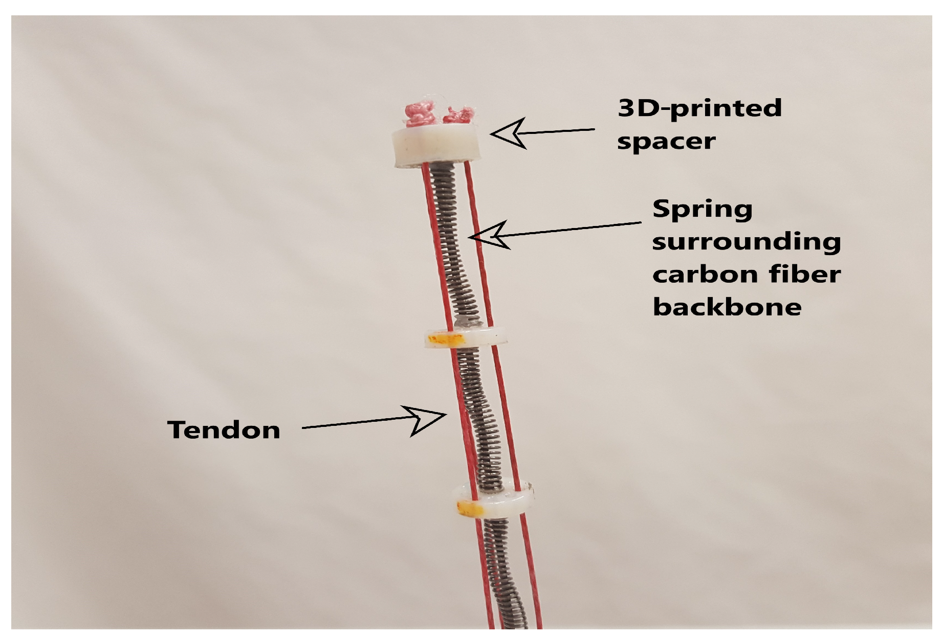
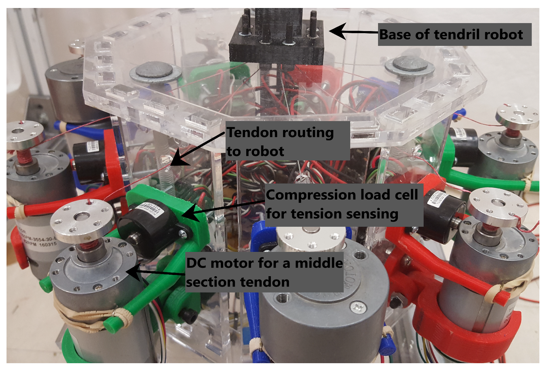
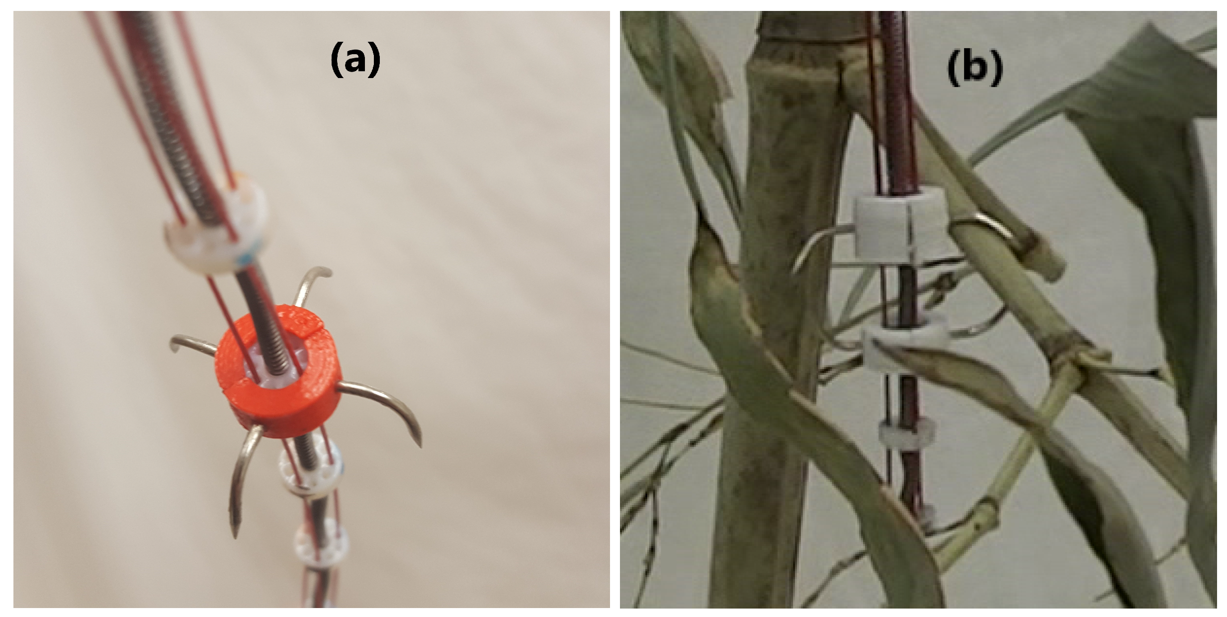
2.1. Plant-Inspired Innovations
The lack of structural support inherent in tendril robot designs tends to generate sagging and buckling when the robot has to support external loading with its structure alone. Thin plants such as vines encounter the same difficulties. However, they have evolved to solve these problems by various means, in particular by actively seeking contact with their environment, bracing against or firmly attaching to it to increase stability. Notice that this is counter to the usual mode of robot navigation, where collisions with the environment are avoided as much as possible.
To find environmental structures to help support themselves, plants utilize motion primitives—in particular, circumnutation—when growing within their environments, which increases the probability of their finding supporting elements. By using the environment for support, plants at least partially decouple distal loads, allowing them to devote most of their energy to linear growth, rather than internal structural support [21,22]. This highly successful strategy combines the efficient motion strategy of circumnutation with specialized “hardware” for environmental attachment. In the following subsections, we review the way this is done by plants and synthesize corresponding elements (attachment hardware and circumnutation motion primitives) for thin continuum robot tendrils.
2.1.1. Plant-Inspired Environmental Contact Hardware
From a physical (hardware) point of view, the way vines exploit their environment, supporting their flexible structures via fixed environmental support, is by the use of specialized structures along their backbones. Different plants have evolved a variety of attachment types, including prickles, thorns, roots or pad structures [21]. Correspondingly, in this paper, we augment the tendril robot of Section 2 with artificial prickles (Figure 3). We reported on initial results with tendril robots using simple artificial prickles made from hooks previously [13]. In that work, we showed that attaching to the environment with these prickles improved stability by reducing coupling proximal to the point of contact [13].
Figure 3.
(a) New prickle design featuring four barbs for attaching to the environment regardless of orientation; (b) new methodology for making environmental contact, featuring two sets of prickles pointed opposite directions.
The simple prickle design above was effective once attachment was made [13], but sometimes, attachment is hard to achieve in a complex environments. Precise orientation was required to consistently engage the environment with these prickle hooks, located 180 apart from each other. The prickles could only attach well when the environment offered a sufficiently small diameter, and at the proper orientation, allowing a good fit for the prickle. Furthermore, the prickles became stuck in the environment at times; good for plants, but for robots, we seek the ability to detach, as well as attach. Hence, two improved designs for attachment hardware are introduced in this paper.
Specialized hardware for adaptive attachment of tendril robots for environmental support increases mechanical complexity and diminishes its ability to maneuver in congested environments. Hence, we designed attachment hardware with the same general scale of the hook prickles, but with better performance. The overall design is still sized to fit around a spacer and has several variations depending on which section’s spacer is is meant to be placed. The hooks are small diameter metal nails bent into the appropriate shape, which is typically between 90 and 120. The size of the hooks is empirically determined to be wide enough to grasp meaningful environmental features, while small enough to allow the robot to enter the environments, particularly the Space Station equipment racks, which were our application focus for this work. One new design, shown in Figure 3a, features four hooks, rather than two. These hooks are separated by approximately ninety degrees, in order to minimize the necessity of precisely orienting the robot in order to engage the environment; thereby facilitating a higher probability of making contact with un-sensed environmental features, which we found to be the case during experiments. The second design, shown in Figure 3b, was a different approach that was meant to improve the contact quality. In either design, attachment and detachment are achieved by manipulating the length of the section that has the set of prickles. For the second design, where a set of prickles is on the first spacer of the tip section, and the last spacer of the middle section, the middle section is extended, while the tip section compresses. Both designs were manufactured in our laboratory by 3D-printing a structure to fit around a spacer with holes through which metal nails can be placed for the prickles.
Bracing against the environment to gain stability has been used as a strategy for conventional rigid link robots [34,35,36]. The notion is quite new for continuum robots, however, and our Section 3 will show how the use of the new prickles introduced in this paper simplifies environmental contact with tendril robots. However, as with plants, an efficient way to explore the environment to seek such contact needs to be found. This issue is addressed in the following subsection.
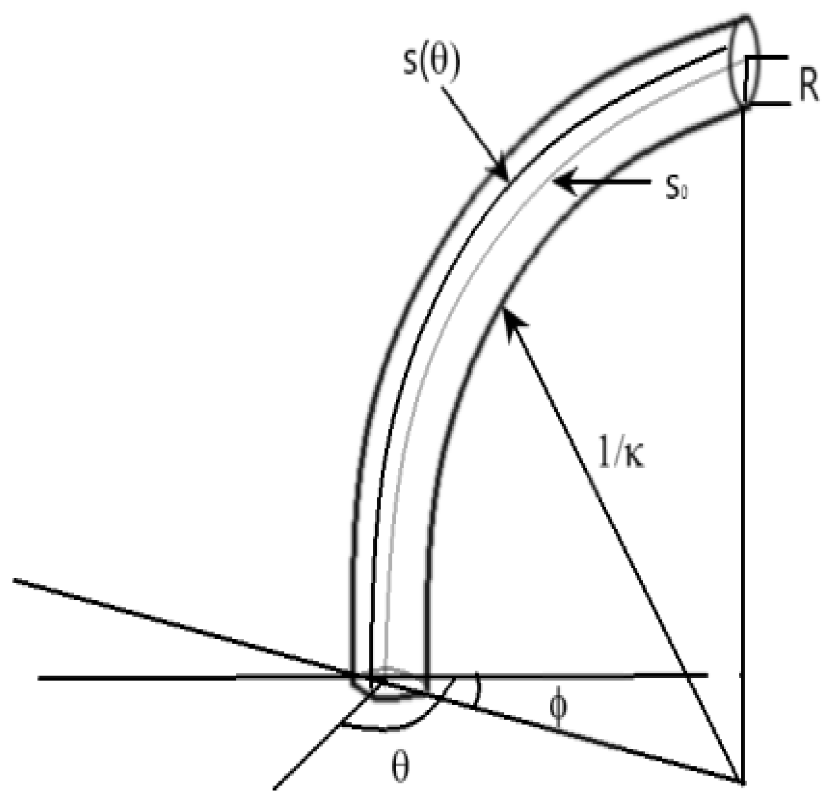
2.1.2. Plant-Inspired Motion Planning: Circumnutation
As noted earlier, circumnutation is an elliptical pattern of growth displayed by the tips of many plants [24] and some roots [18]. Circumnutation movements have been studied in some detail in the botanical literature, both qualitatively [37] and more quantitatively [38]. This “existence proof” for how to move thin, compliant structures has been shown to be an optimal, energy-efficient strategy in the plant world. In the following, we take advantage of the understanding developed and generate a new kinematic model of circumnutation suitable for implementation with tendril-like robots to explore.
Here, we present a new kinematic formulation for extensible continuum robots. The key innovation in the model is that it is explicitly driven by the extension (“growth”) of the outer layer (outer surface of the plant, the layer containing the tendons for continuum robots), which is motivated by similar analyses for plants. This makes it particularly suitable for analyzing plant-inspired movements inherently involving growth such as circumnutation. Note that the approach is different from the kinematics underlying the follow-the-leader movements in [26], in which a Cosserat rod model was used. The kinematics in this paper lacks the inclusion of materials’ properties, but is simpler and, we believe, somewhat more intuitive. The analysis herein extends that in [27,28] in providing a more complete derivation, further insight into the constraints imposed by tendon-actuated continuum robots and a new Jacobian formulation taking into account those constraints. The resulting model is then used, later in this section, as a basis for the synthesis of circumnutation motions in continuum robots.
In order to arrive at a kinematic model of circumnutation suitable for robot simulation and motion generation, the underlying motion needs to be expressed in terms of variables directly related to robot coordinates. To achieve this, in the following, we utilize a kinematic model developed in the botanical literature to model plant circumnutation [25]. That model results in differential kinematics relating changes in local backbone (plant stem) shape (curvature and orientation of curvature ) to changes in backbone length. In the case of plants, this change in length is achieved by growth, which can occur at all points around the circumference of the stem.
In the case of extensible continuum robots, however, “growth” corresponds to increases in actuator lengths and can only occur at finite (with a number equal to the number of independently actuated tendons) and fixed locations around the backbone circumference; the radial angles at which the tendons are routed down the backbone. Therefore, to be applicable to continuum robotics, the plant growth kinematics needs to be restricted to these finite, fixed, locations of “growth” (notice that robots, unlike plants, can “ungrow”, with negative backbone length changes when the tendons decrease, and in this sense, the work in this paper both generalizes and provides an alternative perspective to the plant kinematics in [25]). Figure 4 gives a brief summary of the notation used in this section.
Figure 4.
Image with a description of the notation used in this section.
Assumptions made in formulating the model:
- the radius of the section is R, a constant value
- the backbone section considered has constant curvature with respect to s at any given time t
- the initial curvature of the section is
- the initial length along center line of the section is
- the initial orientation of maximum curvature is , with respect to a fixed coordinate frame fixed at the section base with the z-axis aligned with the section tangent at that point
Note that, at orientation , the constant curvature assumption implies that the section centerline is a circular arc with radius , and defining , the angle subtended by the arc, via:
we can find the length of all lines lying along the section exterior, parallel to the center line, as follows. The length of any line along the exterior of the section, parallel to the center line and at a constant separation R from it, and at a constant angle with respect to as measured in the plane orthogonal to the section tangent, is:
If the section is now deformed, producing a new center line of length , new curvature and new orientation of maximum curvature , at orientation about the exterior, the exterior arc length is, correspondingly,
We next define the growth rate (elongation strain) at a given orientation around the section exterior as the ratio between the elongation length and the original length :
Subsequently, an average growth rate can be defined as:
Then, the deformed center line , and Equation (3) becomes:
Combining (3), (4) and (6):
We expand the above formula, introducing an infinitesimal time step and deformations , , and , neglecting second order infinitesimal terms, to obtain a differential equation for the kinematics:
Equation (8) relates the change of exterior length, at orientation radially about the section, to the rate of change of configuration and average elongation rate .
The above approach was introduced in [25], to analyze the observed growth and circumnutation behavior in plants. A key observation that we exploit here is as follows: defining differential growth as the difference between elongation strain rates on opposite sides of the structure, divided by the average strain rate,
when expanding the expressions for and , the model in (7) simplifies to:
(in which the small quadratic terms are neglected), and:
Equations (10) and (11) give insight into how section configuration shape rates are related to differential growth () and average elongation rate . Note that is the difference in growth rates on opposite sides of the section in the plane of maximum curvature, producing in-plane changes in curvature, and is the equivalent growth rate difference in the plane orthogonal to this, producing out-of-plane changes in section orientation. The configuration rate changes are in each case also linearly related to the average elongation strain rate .
The core modeling approach above was introduced in [25] to model plant growth, specifically circumnutation. However, in this form, it is not suited to adaptation to robotics. For the case of modeling tendon-driven continuum robots, the assumption that the structure can grow at arbitrary locations of about the structure is invalid. This is because the prototype described in the beginning of Section 2 can only independently change its length at a finite number of angles, namely where the tendons are located about its central axis. For the tendril robot in this paper and most other tendon-driven continuum robots, there are three tendon actuators per section, spaced at apart in -space (some tendon-driven continuum robots feature four tendons spaced at apart).
For a continuum section actuated by three tendons arranged at intervals, as for the tendril in this paper, the average elongation strain rate is given by:
where is the strain at the orientation of the i-th tendon. Methods of analyzing and generating motions, including circumnutations, in such continuum robots need to take this into account.
To achieve this, we note that in [25], the differential growth rates can be found as projections of a (as yet unknown) direction of maximal principal growth :
If the direction of maximal principal growth is aligned with one of the three actuators in a continuum robot and the direction is fixed at this angle, then it can be found, using (9)–(11), that the orientation of the plane of maximum curvature is driven to align with the direction of maximum growth, and (using (11)) will remain there. In other words, driving the section with a dominant, single actuator ( will thus become the radial angle corresponding to its tension) will rotate it to align the direction of maximum curvature with that actuator, a result that makes intuitive sense. This observation suggests a new approach to the modeling and generation of continuum robot circumnutations: the elongation of tendons in sequence (note that the tendril is spring loaded, so tendon tension can decrease), successively cycling from tendons i–, and switching when the plane of curvature matches the tendon location. This insight is used in the next section to directly generate both the rotation and extension motions underlying circumnutation in a tendril robot.
The above kinematic model also yields new insight into the underlying capabilities of continuum robots, when the constraints of finite tendons are taken into account. Consider the most common situation in current hardware, where each section of a continuum robot is driven by three tendons equally radially spaced about the backbone at 120° apart. If we refer to a fixed coordinate axis at the base of a section, with the z-axis aligned with the backbone tangent (positive direction distal) and the (x,y) axes (in the plane of a slice through the backbone) fixed such that the x-direction is aligned with Tendon 1 (with corresponding elongation ), we can exploit the kinematic model and underlying geometry to derive the following:
These expressions, combined with the derivative of (12):
define the Jacobian relating task space shape change (extension and bending in two dimensions) to tendon length changes:
This result provides interesting insight. From the perspective of an orientation of one of the tendons (Tendon 1 in this case), bending in the (x) plane is seen to be purely a function of movement of that tendon (note that, unlike the plant growth situation, for this orientation, no “growth” is possible at the orientation opposite Tendon 1, as there is no tendon there).
Furthermore, from this perspective, we see that bending in the perpendicular (y) direction is achieved (even though there are no tendons physically present at the backbone at this orientation, ())= by differential motion between the other two tendons, with the effect attenuated (via the multiplier) by their relative orientational displacement from . Similar relationships can be easily derived for any finite number of tendons and any arbitrary, but known orientations about the backbone. Note that the Jacobian is nonsingular at all times; hence the three-tendon design is inherently stable. This new insight allows for constraints to be placed in the model, based on the locations about the cross-section of tendon-driven continuum robots, where length can be independently changed.
In the next section, we demonstrate the utility of the above new approach to continuum robot kinematics discussed in this subsection, via simulations and experiments using the tendril robot hardware of Section 2.1.1 and exploiting the novel environmental attachment hardware introduced in the previous subsection.
3. Results
The model from Section 2.1.2 was used in both the simulation software and the real-time control software environment developed in our laboratory. MATLAB [39] was used to create the simulation software to model tendril sections in 3D space. This program plots incremental points that represent the location of the virtual tendril’s backbone based on the previously explained model. These points, plotted using Cartesian coordinates, were calculated using the software package built into MATLAB for 3D plotting.
An example of one such simulation is shown in Figure 5. This plot was obtained using stop motion plotting techniques, and they capture the circumnutation movement by displaying multiple instances of robot shape over the same plot axes. Figure 5 simulates the movement of a single section over a set of rotations about its central axis. The gray curves are the projection of the robot on the base (x,y) plane, illustrating the change in tip distance from the z-axis as the robot circumnutates about it in the motion pattern.
Figure 5.
Circumnutation simulation showing the projection of the robot on the base (x,y) plane, showing the change in tip distance from the z-axis for a single section over eight time steps.
In the physical robot, each set of tendons needed to be actuated in sequence to replicate circumnutation motion primitives with the tendril robot. This sequencing was actualized by employing a specific pattern of changing tendon lengths. A subset of one such experiment is given in Table 3. Each row in Table 3 represents a set of changes in tendon length, which are sent to the hardware together using encoder count targets, which are specific to the hardware, but cause the specified change in tendon length. Every time this happens, each motor moved in such a way as to reach its individual encoder count target. This procedure implemented the theory of circumnutation discussed in Section 2.1.2 in hardware. Moving in this way, the robotic section both bent and extended, effectively “growing” into the environment, similar to how plants move.
Table 3.
An excerpt of the changes in tendon lengths, in millimeters, that resulted in circumnutation.
The motion primitives for circumnutation were programmed algorithmically. This method formalizes the procedure discussed in [27] to allow movement using any given section, or multiple sections, for a non-extensible tendril robot. Before starting the circumnutation movement, the user is able to choose the sections to perform the circumnutation movements, but in any combination. Afterwards, each set of motors that were chosen to move were listed in a function in the control code. These motor numbers ranged from 0–8, for a total of nine motors. The motors that control the base section were Motors 0–2, 3–5 for the middle section and 6–8 for the tip. As an example, if the tip and middle sections were chosen, then an array containing [3, 4, 5, 6, 7, 8] would be sent as input to this function. The tendons that actuate sections that are not circumnutating were not actuated as their movement was not necessary to achieve the desired motion. Next, the circumnutation function would shorten the tendons of Motors 3 and 6 by a predetermined length, but typically between five and ten millimeters for the hardware prototype described herein. Following this, the program would then shorten tendon length in the next two motors to be actuated afterwards in the sequence until the tendon tension in both the first and second tendons was approximately equal. Then, the first two motors tendons were released, causing the bending to coincide with the second set of tendons. By actively taking up the tendon slack, we found the assumption of instantaneous change in tendon length to be supported empirically. For this example, those would be Motors 4 and 7. Finally, this pattern is repeated and would loop back to Motors 3 and 6 after it has reached the end of each iteration, and would continue until the program reached a set number of iterations. By doing so, this procedure produced a motion primitive in the hardware that closely mimicked the growing movements of many plants and vines. To produce this same motion in an extensible version of the hardware, presented in Section 2, the process was reversed. All tendons of a section that was to circumnutate were shortened until maximum compression was achieved. Then, each tendon lengthened in sequence, with a tendon lengthening relative to the previous by a predetermined amount. In Table 3, this amount is approximately five millimeters. In this way, each time a tendon was lengthened, it became longer than the previous, which created the “growing” effect as the hardware performed the motion primitive. As this happened, the slack was taken up by the springs about the carbon fiber backbone.
A sequence of images illustrating the implementation of the procedure, mentioned above, is shown in Figure 6, using the robotic hardware. These motions were produced, in part, using the changes in tendon lengths given in Table 3.
Figure 6.
Circumnutation with tendril robot.
The algorithm is given below for circumnutation with a robot that is spring-loaded.
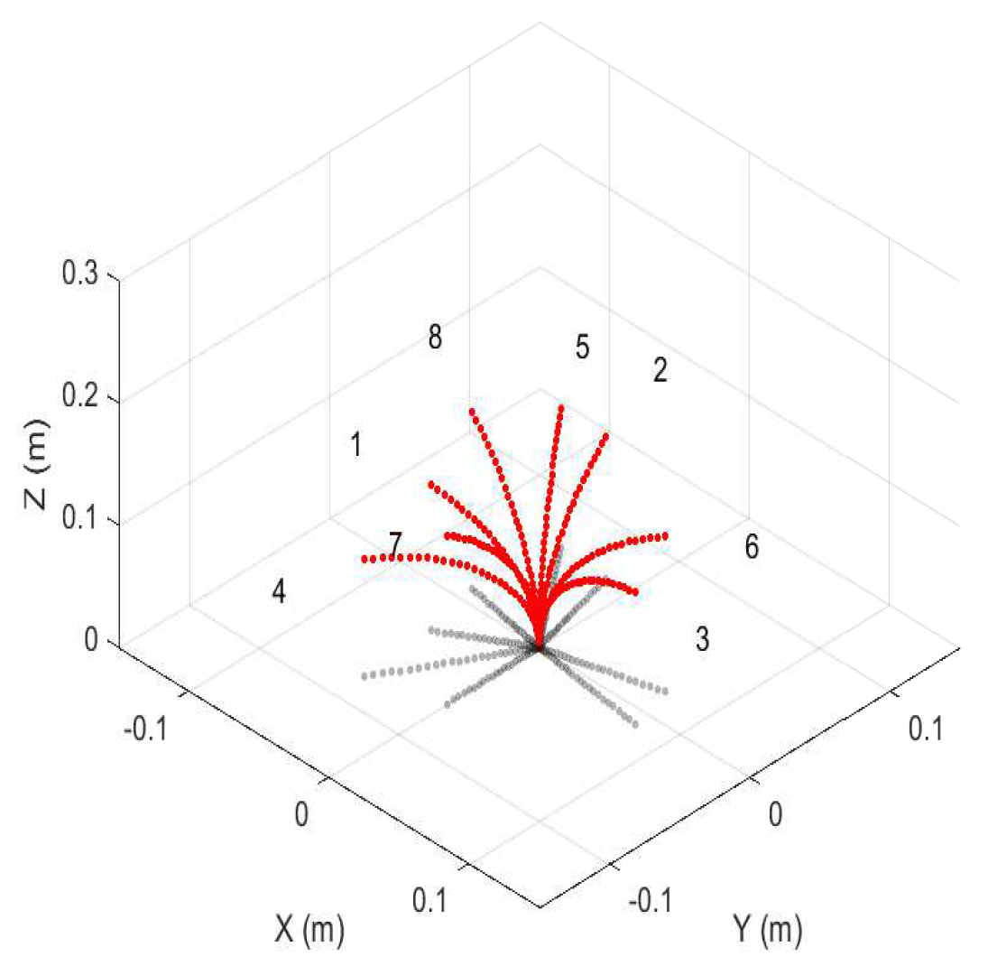
- The user chooses the motors and therefore sections to circumnutate, along with the number of motors included in the movement
- These values are then stored into an array
- (a)
- i.e., the distal section is controlled by Motors 6, 7, and 8, 3, and so on
- Wind the motors to maximum compression
- Unwind the first motor in each set by a predetermined length
- Enter a loop structure that is set to execute a predetermined number of times
- (a)
- Loop until all motors have unwound by a small amount (usually three)
- i
- Unwind the next motor in the sequence to a length greater than the previous one
- ii
- Go to 5-a until the condition is met
- (b)
- Increment the counter
- (c)
- Go to 4 unless the increment of the counter equals the max iterations
By further applying the techniques and insights developed and discussed in previous sections, more experiments were conducted to quantitatively and qualitatively show the benefits of said movement strategies. One such example is shown in Figure 7. During these experiments, the aforementioned procedure for recreating circumnutation motion primitives was used to find the desired environmental contact. While extending into the environment, the robot’s motion pattern was wide enough so as to be able to find an adequate point of attachment before beginning the process of attaching to the environment. Once a possible attachment point was located, the new prickle design was employed to make the attachment. This was done by retracting all three tendons of that section at the same rate. This effectively shortened the section with the installed prickle and allowed the prickle to actively engage that particular point in the environment. The circumnutation movement performed by the robot was found to cause the robot to bypass environmental elements that would not lead to an effective point of attachment easily.
Figure 7.
Circumnutation with tendril robot ending in achieving environmental attachment.
Another set of experiments was conducted to track the tip of the robot during the circumnutation movement. While circumnutating, using the algorithm described above, the robot’s tip position data were measured at several points as it moved in three-dimensional space.
The plot of these data is shown in Figure 8. It shows the tip moving in an elliptical, growing circumnutation pattern. The movement was not a perfectly smooth, elliptical pattern due to structural imperfections introduced in the manufacturing process, as well as measurement error. However, it clearly is shown that the pattern of circumnutation effectively widened the area that the tip explored as it entered an environment, which increased the likelihood that environment contact would be encountered. The data used for this plot are given in Table 4.
Figure 8.
(a) Trace of the tip as it circumnutates, seen from the top. The red circles are the path during the first circumnutation, and the blue crosses are the path of the second circumnutation. (b) Trace of the tip as it circumnutates from a three-dimensional perspective.
Table 4.
Measured tip position data.
These values were then compared to simulation output using the root mean square of the differences between the x, y and z values of the experimental data and the simulation output. The root mean square values are presented in Table 5.
Table 5.
RMS values of the difference between experimental and simulated tip positions.
The simulation did not account for coupling between sections or physical characteristics that determined how much a shortening tendon will cause the robot to bend or compress. The large differences in Z were primarily due to error introduced when the data were recorded and the tendency of the middle section to also compress when when the tip tendons shortened. We observed that by modifying how the tendon lengths related to changing encoder counts, it was possible to reduce the error in the x-y plane. This value could therefore be modified for different robotic prototypes and varying designs of the same basic hardware, which would need to be done anyway, to account for physical characteristics that were not accounted for in the geometric model.
4. Discussion and Conclusions
This paper discusses a new and novel approach to motion planning for long, thin tendril continuum robots. Drawing inspiration from strategies employed by plants, and particularly vines, we show how oscillatory movements known as circumnutation can be implemented with tendril robots, generating a new type of robot motion primitive and resulting environmental exploration strategy. To model and generate the circumnutation motions, we introduce and analyze a new kinematic model for extensible continuum robots, adapted to robotics from a model in the plant growth literature. We support the analysis with experimental results using a tendril robot performing circumnutation to more efficiently achieve environmental exploration and contact, using novel attachment hardware also introduced in this paper. In the future, circumnutation algorithms and environmental contact strategies are anticipated to be key parts of a suite of methodologies, which will enable continuum robots to be more widely used.
Author Contributions
Conceptualization, M.W. and I.D. Methodology, I.D. Software, M.W. Validation, M.W. Formal analysis, I.D. Investigation, M.W. Resources, I.D. Data curation, M.W. Writing, original draft preparation, M.W. and I.D. Writing, review and editing, M.W. and I.D. Visualization, M.W. Supervision, I.D. Project administration, I.D. Funding acquisition, I.D.
Funding
This work is supported in part by the U.S. National Science Foundation under Grants IIS-1527165 and IIS-1718075 and in part by NASA under Contract NNX12AM01G.
Acknowledgments
We would like to thank Chase Frazelle for all his efforts to help produce the simulation images used in this paper.
Conflicts of Interest
The authors declare no conflict of interest.
Abbreviations
The following abbreviations are used in this manuscript:
| OD | outer diameter |
| ID | inner diameter |
| DC | direct current |
| PWM | pulse width modulated |
| RMS | root mean square |
References
- Trivedi, D.; Rahn, C.D.; Kier, W.M.; Walker, I.D. Soft Robotics: Biological Inspiration, State of the Art, and Future Research. Appl. Bionics Biomech. 2008, 5, 99–117. [Google Scholar] [CrossRef]
- Meyer, J.A.; Guillot, A. Biologically Inspired Robots. In Springer Handbook of Robotics; Springer-Verlag Berlin Heidelberg: Berlin, Germany, 2008; pp. 1395–1418. [Google Scholar]
- Walker, I.D. Continuous Backbone “Continuum” Robot Manipulators: A Review. ISRN Robot. 2013, 2013. [Google Scholar] [CrossRef]
- Robinson, G.; Davies, J. Continuum Robots—A State of the Art. In Proceedings of the IEEE International Conference on Robotics and Automation, Detroit, MI, USA, 10–15 May 1999; pp. 2849–2854. [Google Scholar]
- Burgner-Kars, J.; Rucker, D.; Choset, H. Continuum Robots for Medical Applications: A Survey. IEEE Trans. Robot. 2015, 31, 1261–1280. [Google Scholar] [CrossRef]
- Chitalia, Y.; Wang, X.; Desai, J.P. Design, Modeling and Control of a 2-DoF Robotic Guidewire. In Proceedings of the IEEE International Conference on Robotics and Automation, Brisbane, Australia, 21–25 May 2018; pp. 32–37. [Google Scholar]
- Liu, N.; Abdelaziz, M.E.M.K.; Shen, M.; Yang, G.Z. Design and Kinematics Characterization of a Laser-Profiled Continuum Manipulator for the Guidance of Bronchoscopic Instruments. In Proceedings of the IEEE International Conference on Robotics and Automation, Brisbane, Australia, 21–25 May 2018; pp. 25–31. [Google Scholar]
- Webster III, R.J.; Jones, B.A. Design and Kinematic Modeling of Constant Curvature Continuum Robots: A Review. Int. J. Robot. Res. 2010, 29, 1661–1683. [Google Scholar] [CrossRef]
- Walker, I.D. Robot Strings: Long, Thin Continuum Robots. In Proceedings of the IEEE Aerospace Conference, Big Sky, MT, USA, 2–9 March 2013; pp. 1–12. [Google Scholar]
- Mehling, J.; Diftler, M.; Chu, M.; Valvo, M. A Minimally Invasive Tendril Robot for In-Space Inspection. In Proceedings of the International Conference on BioRobotics, Pisa, Italy, 20–22 February 2006; pp. 690–695. [Google Scholar]
- Moravec, H. Mind Children: The Future of Robot and Human Intelligence; Harvard University Press: Cambridge, MA, USA, 1988. [Google Scholar]
- Martone, P.; Boller, M.; Burgert, I.; Dumais, J.; Edwards, J.; Mach, K.; Rowe, N.; Rueggeberg, M.; Seidel, R.; Speck, T. Mechanics Without Muscle: Biomechanical Inspiration from the Plant World. Integr. Comp. Biol. 2010, 50, 888–907. [Google Scholar] [CrossRef] [PubMed]
- Wooten, M.; Walker, I. A Novel Vine-Like Robot for In-Orbit Inspection. In Proceedings of the 45th International Conference on Environmental Systems, Bellevue, WA, USA, 12–16 July 2015; pp. 1–11. [Google Scholar]
- Hawkes, E.W.; Blumenschein, L.H.; Greer, J.D.; Okamura, A.M. A soft robot that navigates its environment through growth. Sci. Robot. 2017. [Google Scholar] [CrossRef]
- Blumenschein, L.H.; Okamura, A.M.; Hawkes, E.W. Modeling of Bioinspired Apical Extension in a Soft Robot. In Conference on Biomimetic and Biohybrid Systems; Living Machines: Stanford, CA, USA, 2017; pp. 522–531. [Google Scholar]
- Mazzolai, B.; Beccai, L.; Mattoli, V. Plants as Model in Biomimetics and Biorobotics: New Perspectives. Front. Bioeng. Biotechnol. 2014, 2, 1–5. [Google Scholar] [CrossRef] [PubMed]
- Sadeghi, A.; Tonazzini, A.; Popova, I.; Mazzolai, B. Robotic Mechanism for Soil Penetration Inspired by Plant Root. In Proceedings of the IEEE International Conference on Robotics and Automation, Karlsruhe, Germany, 6–10 May 2013; pp. 3457–3462. [Google Scholar]
- Del Dottore, E.; Mondini, A.; Sadeghi, A.; Mattoli, V.; Mazzolai, B. Circumnutations as a penetration strategy in a plant-root-inspired robot. In Proceedings of the IEEE International Conference on Robotics and Automation, Stockholm, Sweden, 16–21 May 2016; pp. 4722–4728. [Google Scholar]
- Del Dottore, E.; Sadeghi, A.; Mondini, A.; Mazzolai, B. Continuous growth in plant-inspired robots through 3D additive manufacturing. In Proceedings of the IEEE International Conference on Robotics and Automation, Brisbane, Australia, 21–25 May 2018; pp. 3454–3460. [Google Scholar]
- Greer, J.D.; Blumenschein, L.H.; Okamura, A.M.; Hawkes, E.W. Obstacle-Aided Navigation of a Soft Growing Robot. In Proceedings of the IEEE International Conference on Robotics and Automation, Brisbane, Australia, 21–25 May 2018; pp. 4165–4172. [Google Scholar]
- Goriely, A.; Neukirch, S. Mechanics of Climbing and Attachment in Twining Plants. Phys. Rev. Lett. 2006, 97, 184302. [Google Scholar] [CrossRef] [PubMed]
- Putz, F.; Mooney, H. The Biology of Vines; Cambridge University Press: Cambridge, MA, USA, 1991. [Google Scholar]
- Darwin, C. The Movements and Habits of Climbing Plants; John Murray: London, UK, 1875. [Google Scholar]
- Isnard, S.; Silk, W. Moving with Climbing Plants from Charles Darwin’s Time into the 21st Century. Am. J. Bot. 2009, 96, 1205–1221. [Google Scholar] [CrossRef] [PubMed]
- Bastien, R.; Meroz, Y. The Kinematics of Plant Nutation Reveals a Simple Relation Between Curvature and the Orientation of Differential Growth. PLOS Comput. Biol. 2016, 12, e1005238. [Google Scholar] [CrossRef] [PubMed]
- Neumann, M.; Burgner-Kahrs, J. Considerations for Follow-The-Leader Motion of Extensible Tendon-driven Continuum Robots. In Proceedings of the IEEE International Conference on Robotics and Automation, Stockholm, Sweden, 16–21 May 2016; pp. 917–923. [Google Scholar]
- Wooten, M.B.; Walker, I.D. Circumnutation: From Plants to Robots. In From Animals to Animats 14, Proceedings of the 14th International Conference on Simulation of Adaptive Behavior, SAB 2016, Aberystwyth, UK, 23–26 August 2016; Tuci, E., Giagkos, A., Wilson, M., Hallam, J., Eds.; Springer International Publishing: Cham, Switzerland, 2016; pp. 1–11. [Google Scholar]
- Wooten, M.; Frazelle, C.; Walker, I.; Kapadia, A.; Lee, J. Exploration and Inspection with Vine-Inspired Continuum Robots. In Proceedings of the IEEE International Conference on Robotics and Automation, Brisbane, Australia, 21–25 May 2018; pp. 5526–5533. [Google Scholar]
- Tonapi, M.; Godage, I.; Vijaykumar, A.; Walker, I. Spatial Kinematic Modeling of a Long and Thin Continuum Robotic Cable. In Proceedings of the IEEE International Conference on Robotics and Automation, Seattle, WA, USA, 26–30 May 2015; pp. 3755–3761. [Google Scholar]
- Jones, B.; Walker, I. Kinematics for Multisection Continuum Robots. IEEE Trans. Robot. 2006, 22, 43–57. [Google Scholar] [CrossRef]
- Li, J.; Teng, Z.; Xiao, J.; Kapadia, A.; Bartow, A.; Walker, I. Autonomous Continuum Grasping. In Proceedings of the IEEE/RSJ International Conference on Intelligent Robots and Systems, Tokyo, Japan, 3–7 November 2013; pp. 4569–4576. [Google Scholar]
- Buckingham, R. Snake Arm Robots. Ind. Robot Int. J. 2002, 29, 242–245. [Google Scholar] [CrossRef]
- Truong-Thinh, N.; Ngoc-Phuong, N. Design and Development of a Continuum Structure for Robotic Flower. In Proceedings of the IEEE Conference on Robotics and Biomimetics, Phuket, Thailand, 7–11 December 2011; pp. 118–123. [Google Scholar]
- Book, W.; Le, S.; Sangveraphunsiri, V. The bracing strategy for robot operation. In Proceedings of the 5th Symposium on Theory and Practise of Robots and Manipulators, Udine, Italy, 26–29 June 1984; pp. 179–186. [Google Scholar]
- Bullock, I.; Ma, R.; Dollar, A. A hand-centric classification of human and robot dexterous manipulation. IEEE Trans. Haptics 2013, 6, 129–144. [Google Scholar] [CrossRef] [PubMed]
- Hollis, R.; Hammer, R. Real and virtual coarse-fine robot bracing strategies for precision assembly. In Proceedings of the IEEE International Conference on Robotics and Automation, Nice, France, 12–14 May 1992; pp. 767–774. [Google Scholar]
- Brown, A. Circumnutations: From Darwin to Space Flights. Plant Physiol. 1993, 101, 345–348. [Google Scholar] [CrossRef] [PubMed]
- Niklas, K.J.; Spatz, H.C. Plant Physics; University of Chicago Press: Chicago, IL, USA, 2012. [Google Scholar]
- MathWorks. MATLAB, 2017. Available online: www.mathworks.com (accessed on 18 September 2018).
© 2018 by the authors. Licensee MDPI, Basel, Switzerland. This article is an open access article distributed under the terms and conditions of the Creative Commons Attribution (CC BY) license (http://creativecommons.org/licenses/by/4.0/).