Maximal Singularity-Free Orientation Subregions Associated with Initial Parallel Manipulator Configuration


Abstract
1. Introduction
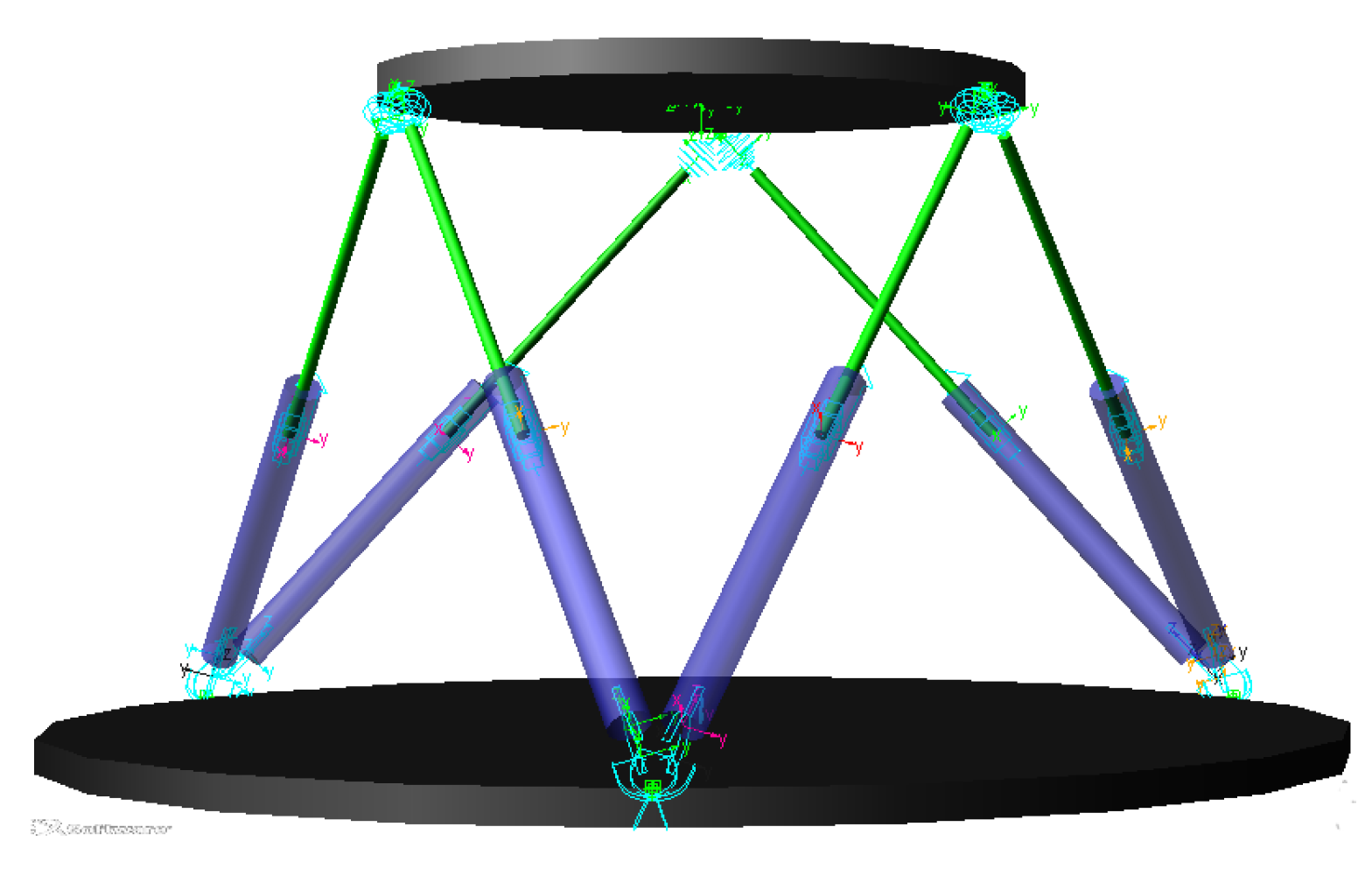
2. Kinematic of S-G
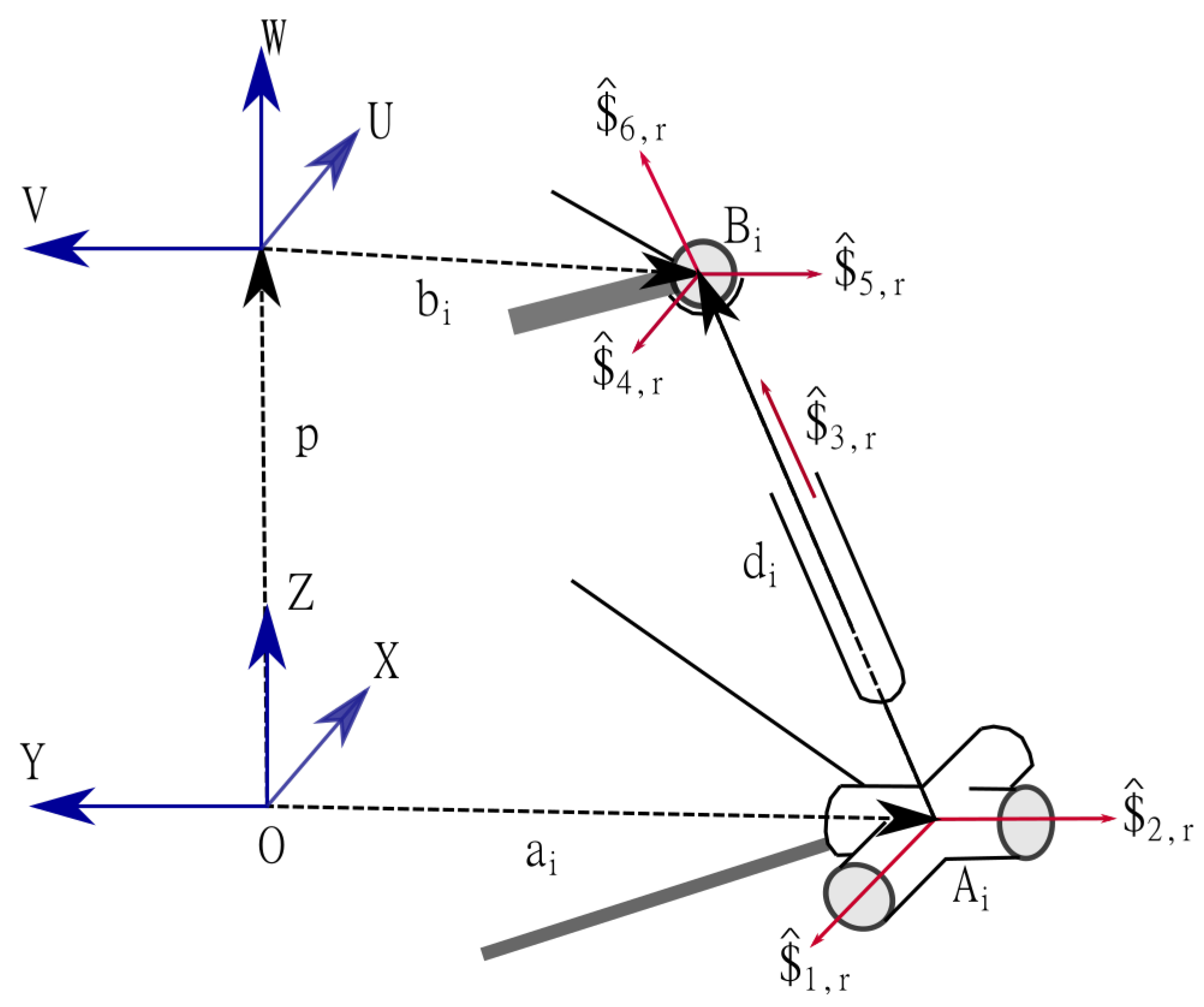
2.1. Screw and Reciprocal Screw
2.2. Screw-Based Jacobian
3. Constraints Formulation
3.1. Kinematic Singularities Analysis
3.1.1. Inverse Singularity
3.1.2. Direct Singularity
3.2. Geometrical Constraint
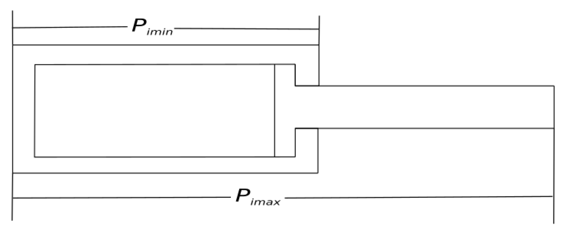
3.2.1. Prismatic Joint
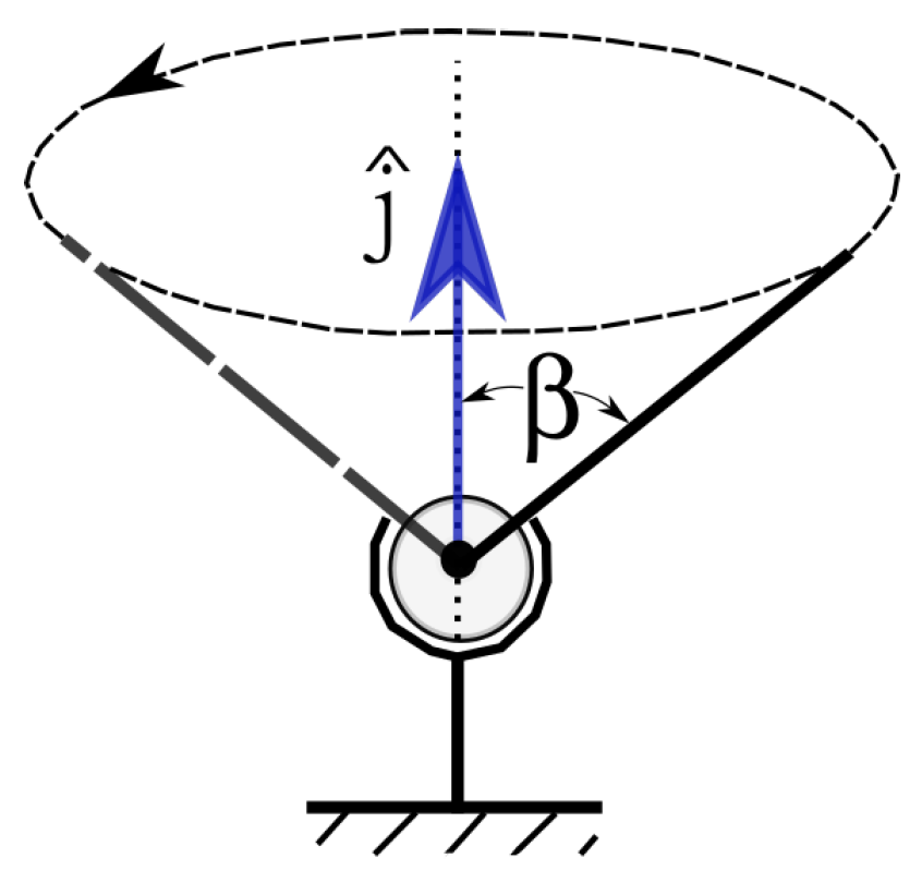
3.2.2. Spherical Joint
3.2.3. Kinematic Chain Collision
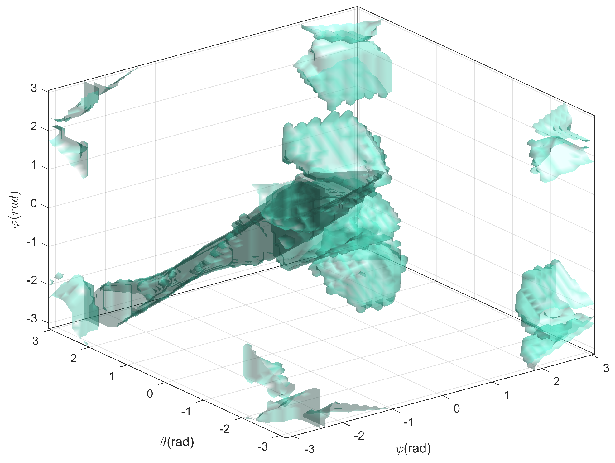
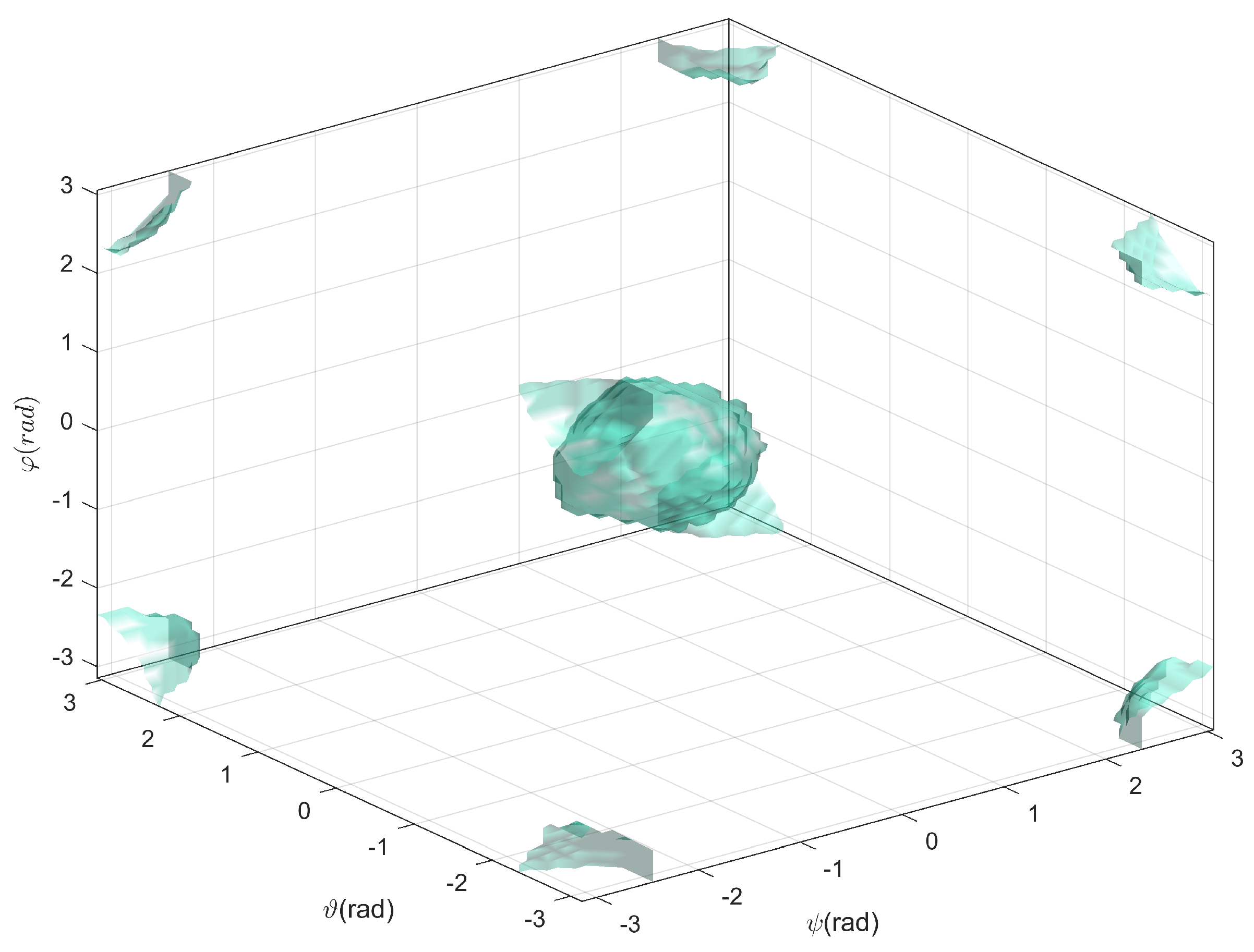
4. Workspace Analysis
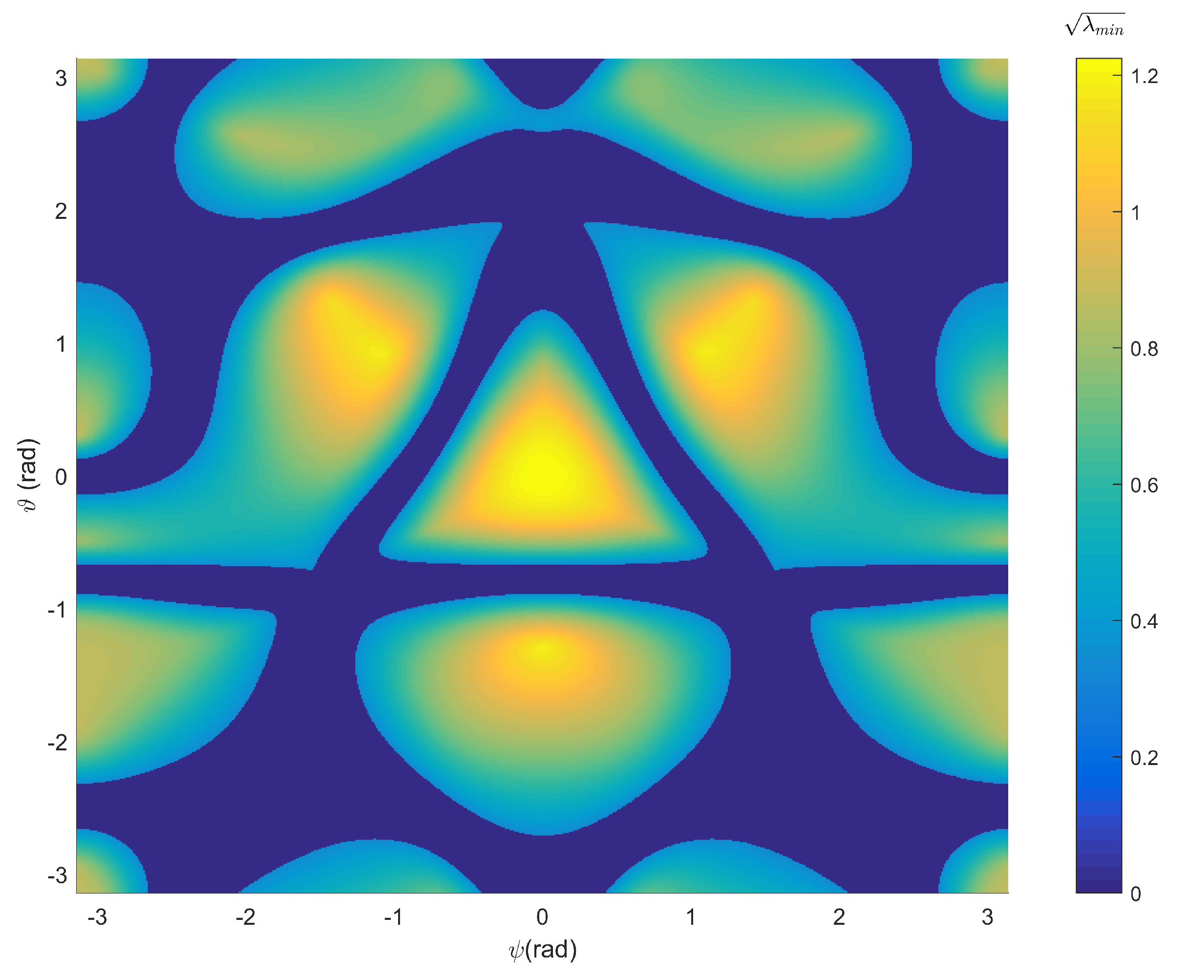
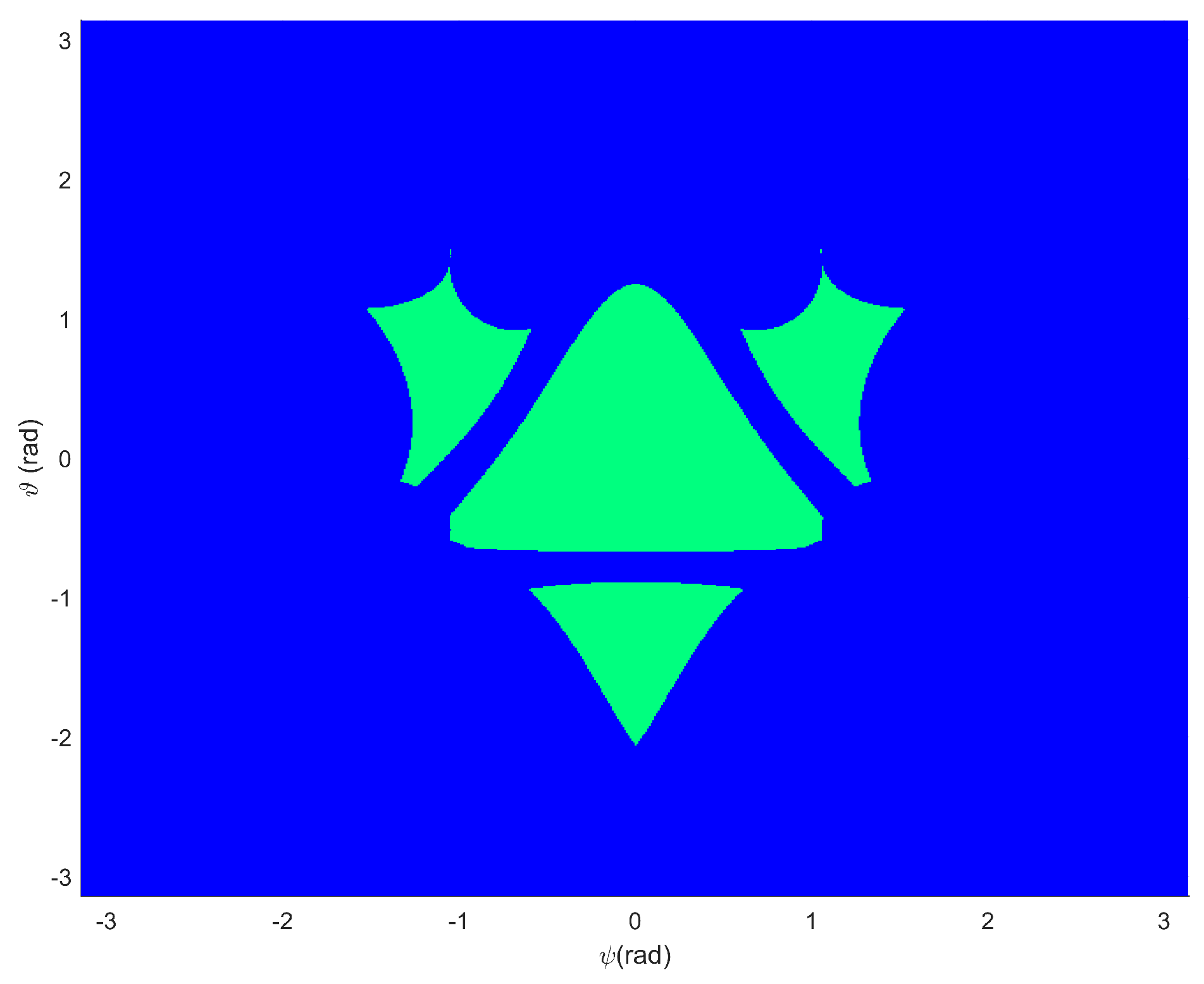
4.1. Direct Singularity
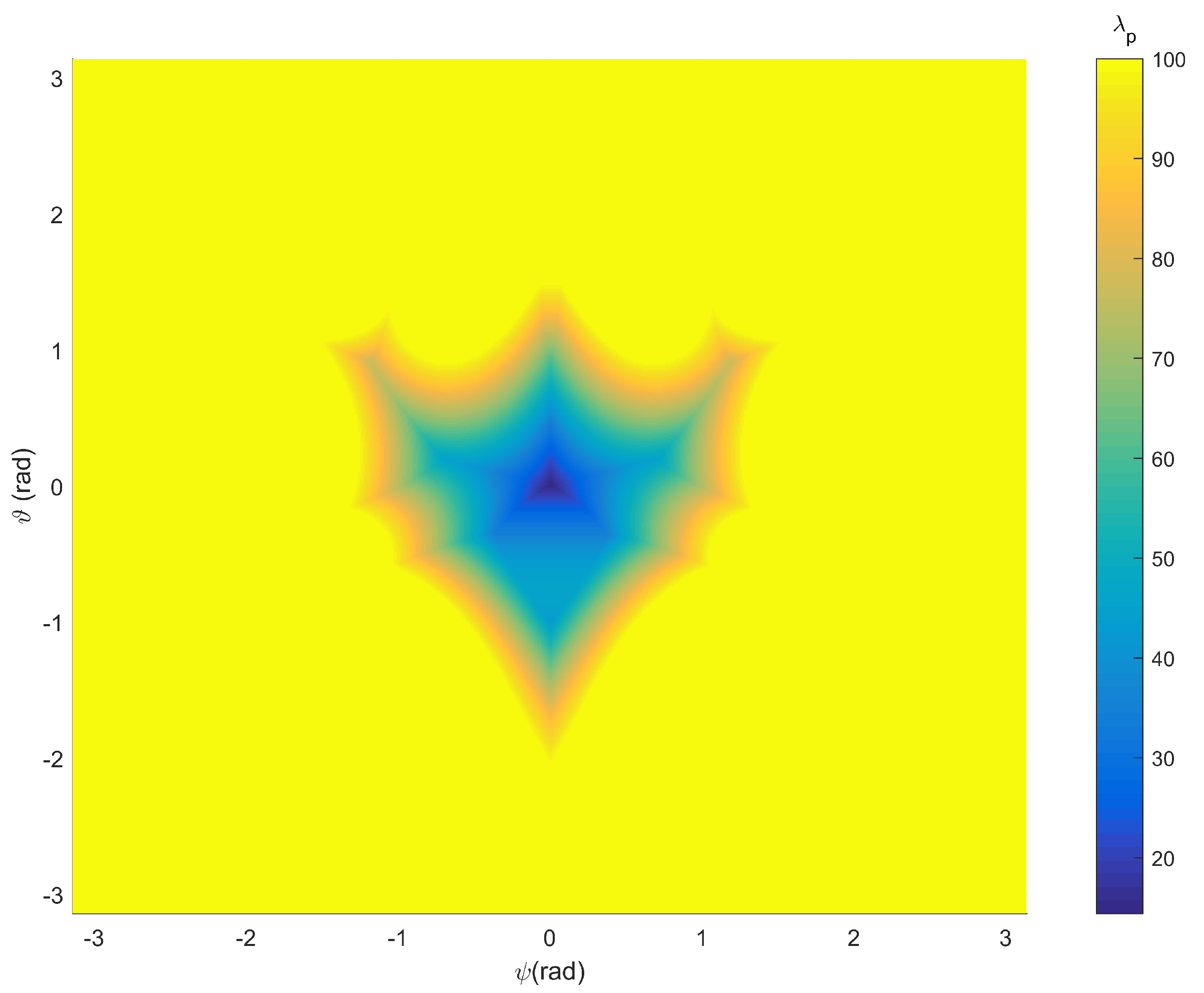
4.2. Geometrical Constraints
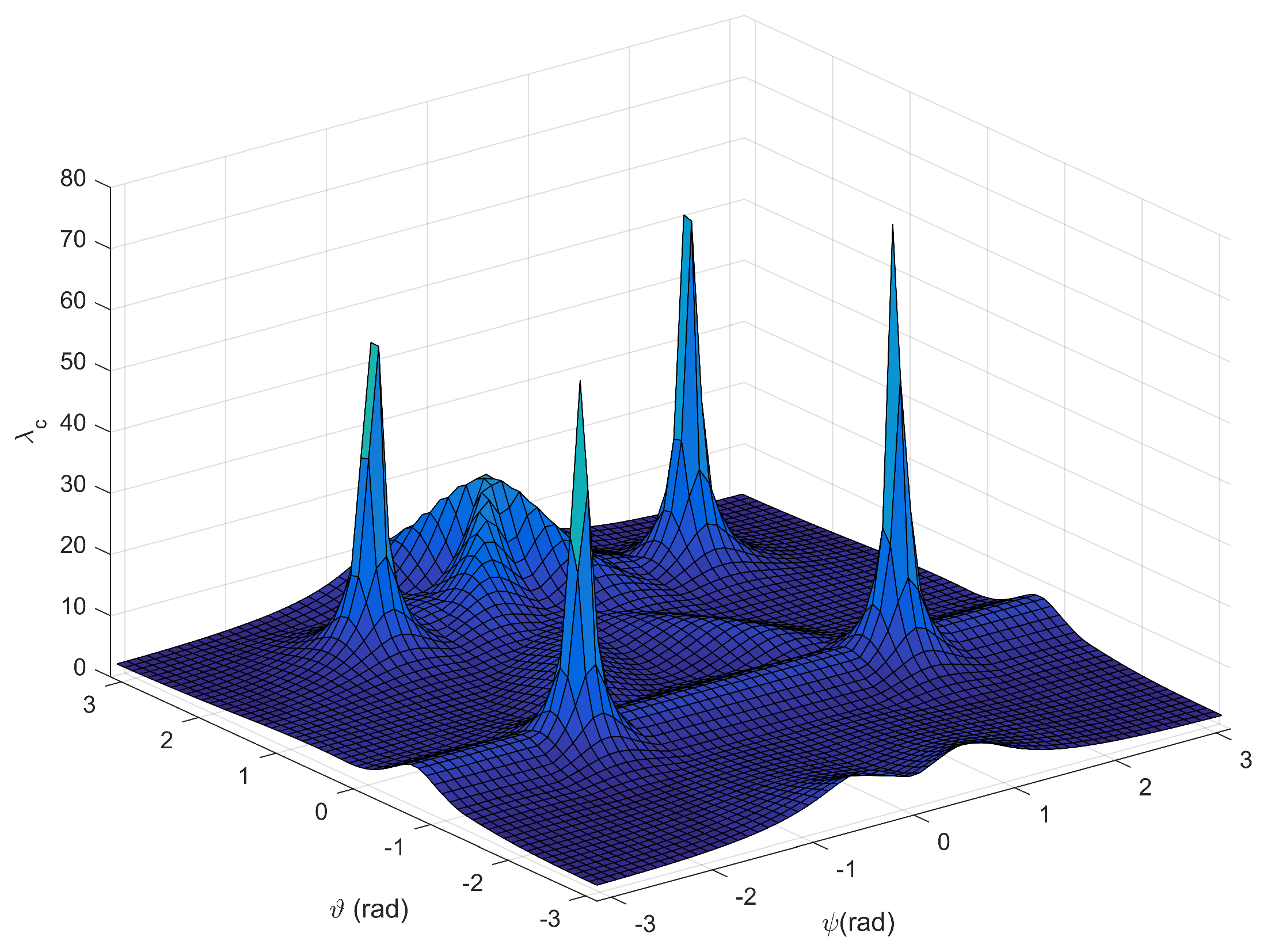
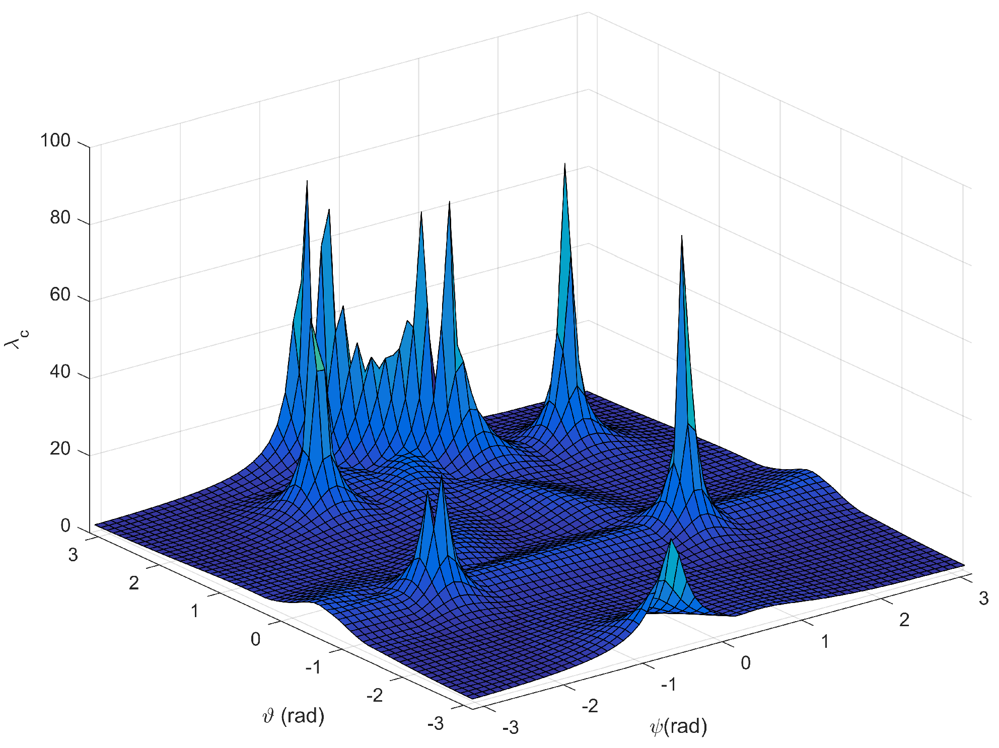
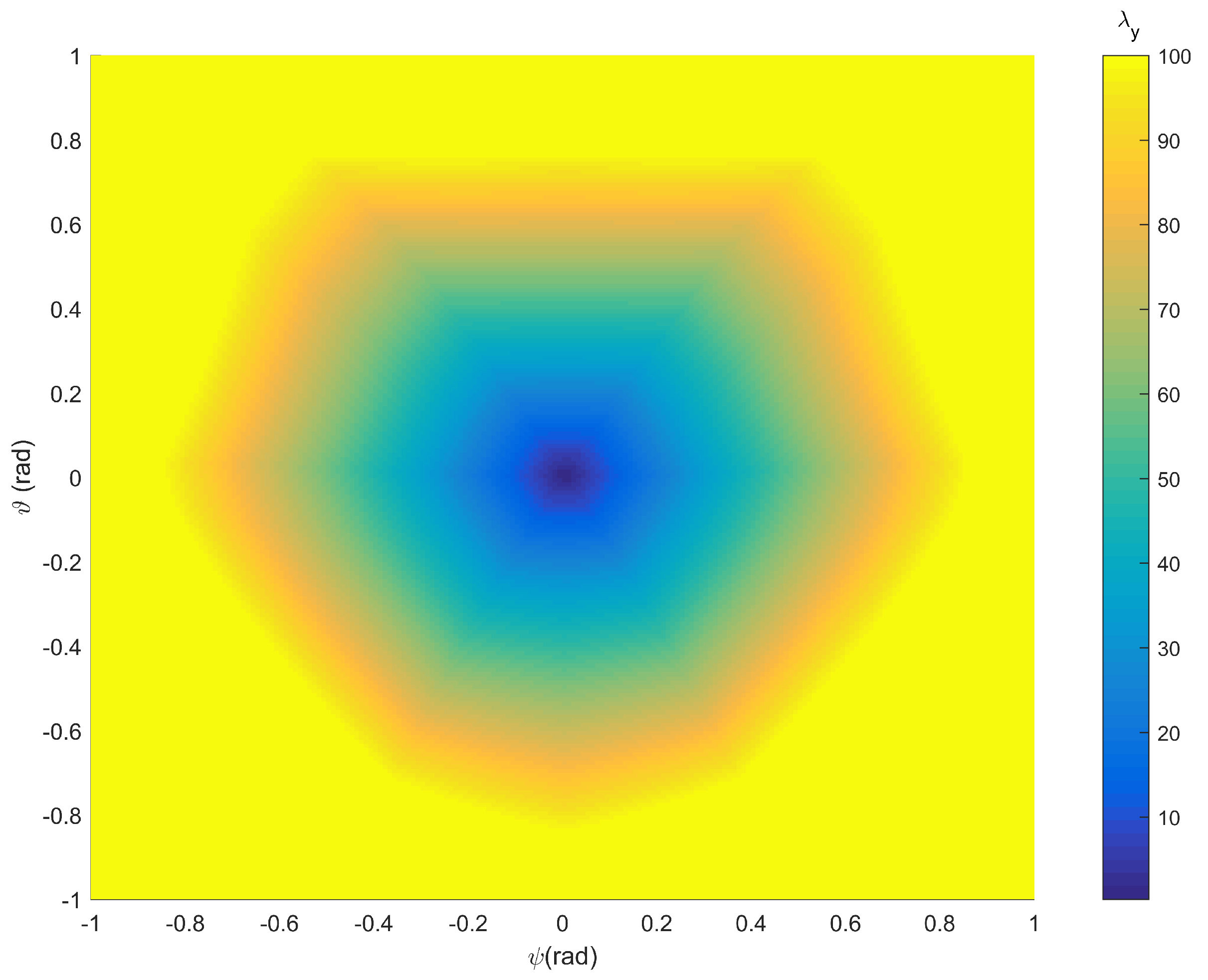
5. Workspace Optimization
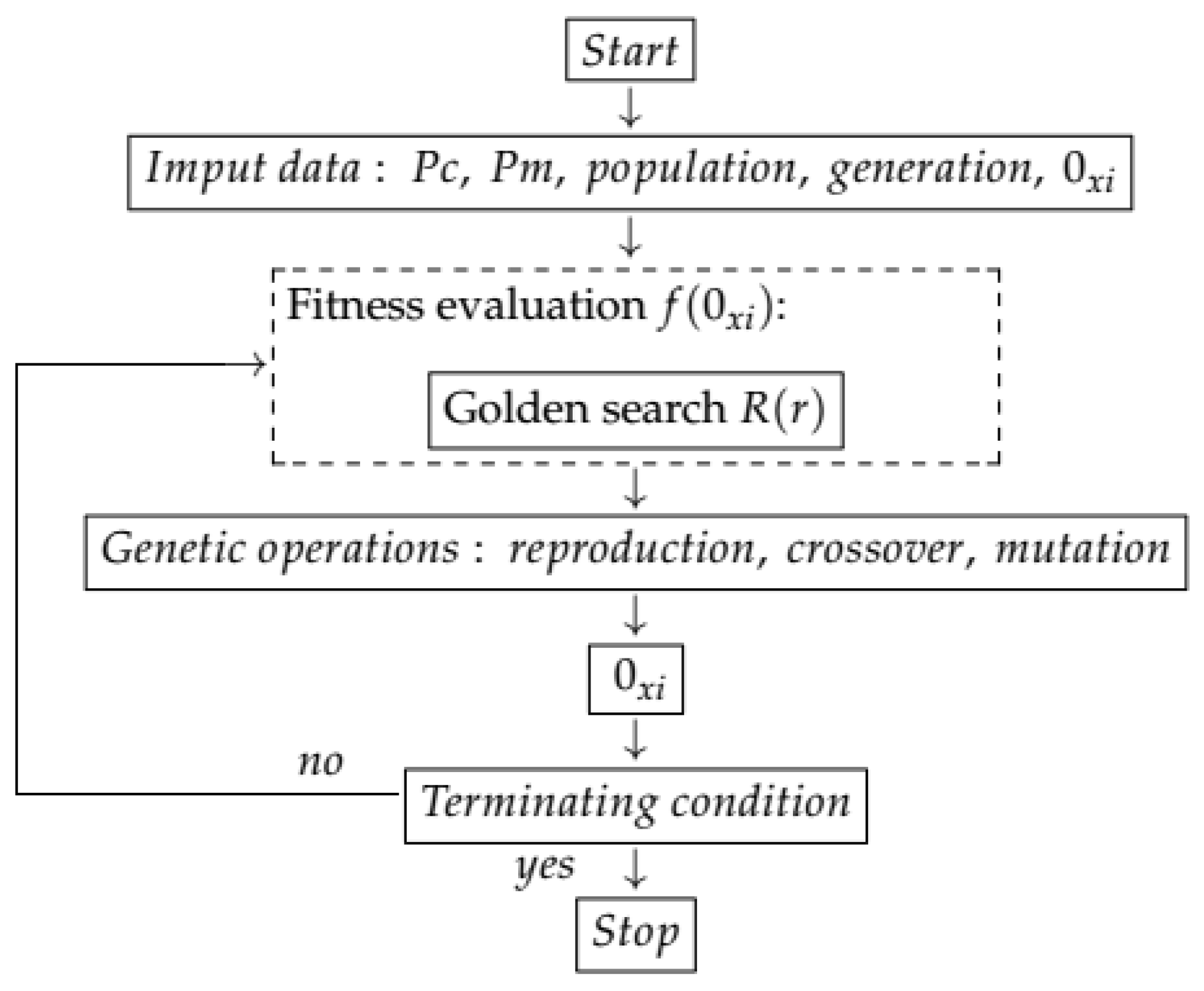
5.1. Genetic Algorithm (GA)
5.1.1. Reproduction
5.1.2. Crossover
5.1.3. Mutation
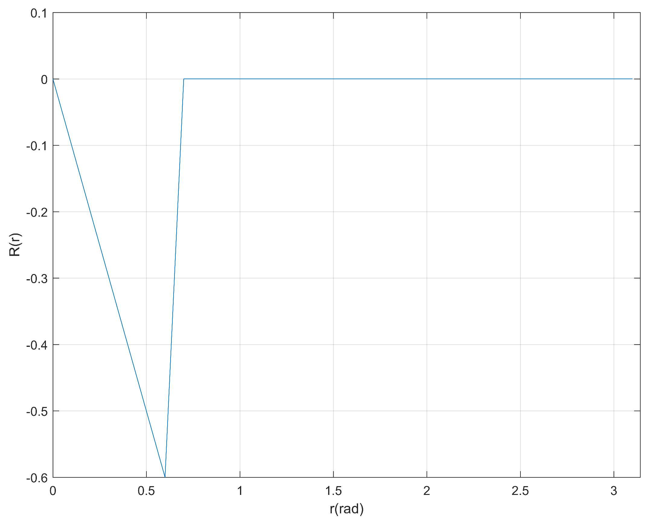
5.1.4. Objective Function
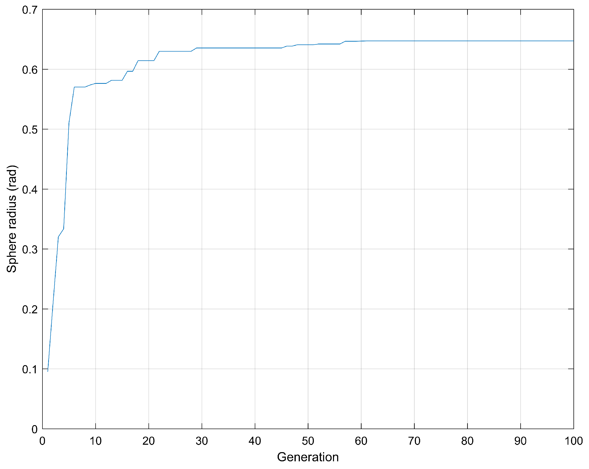
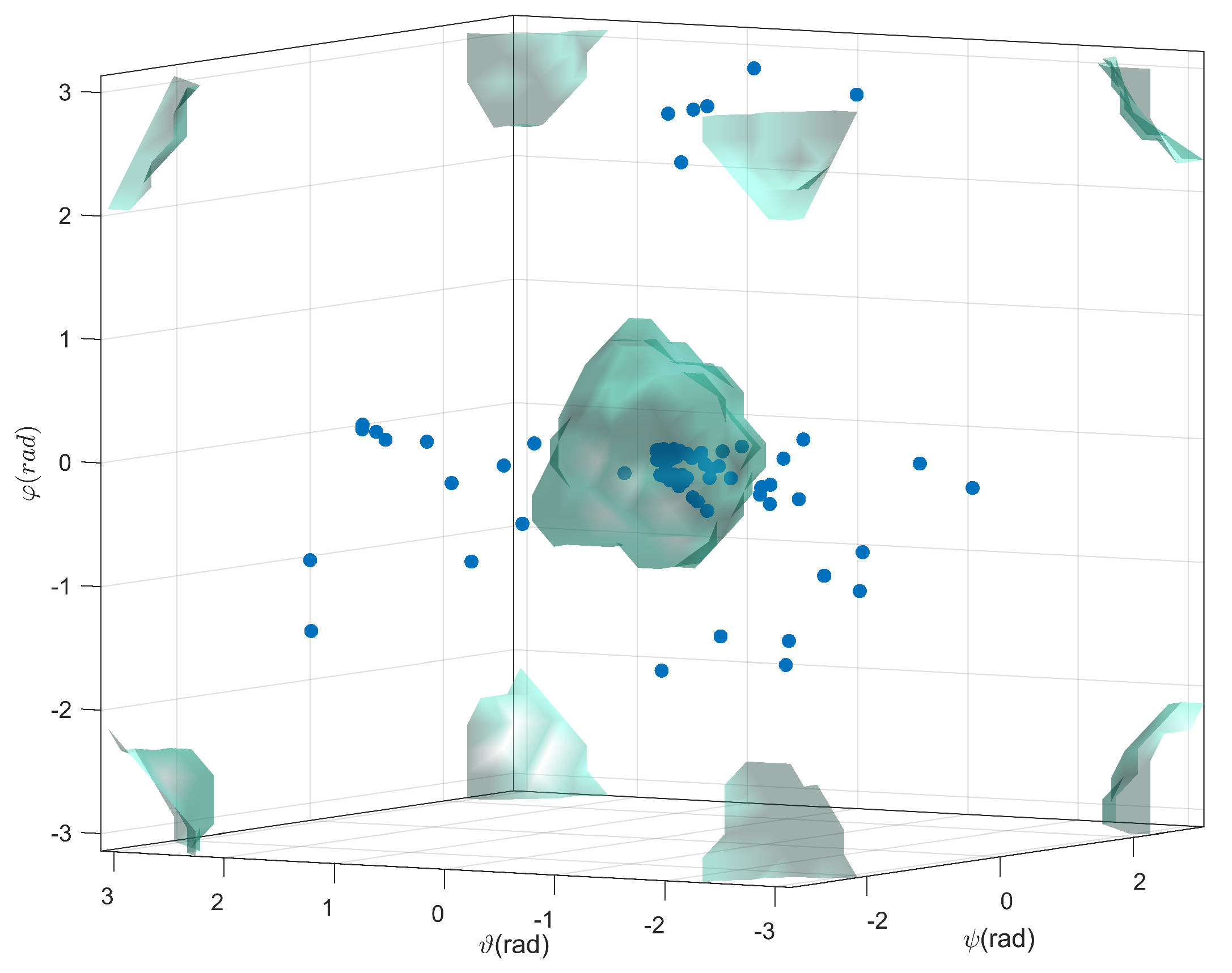
5.2. Optimization
6. Conclusions
Author Contributions
Acknowledgments
Conflicts of Interest
References
- Tsai, L.W. Robot Analysis: The Mechanics of Serial and Parallel Manipulators; John Wiley & Sons: Hoboken, NJ, USA, 1999. [Google Scholar]
- Gao, Z.; Zhang, D. Workspace representation and optimization of a novel parallel mechanism with three-degrees-of-freedom. Sustainability 2011, 3, 2217–2228. [Google Scholar] [CrossRef]
- Pott, A. Efficient Computation of the Workspace Boundary, Its Properties and Derivatives for Cable-Driven Parallel Robots. In Computational Kinematics; Springer: Dordrecht, The Nertherlands, 2018; pp. 190–197. [Google Scholar]
- Bayani, H.; Masouleh, M.T.; Karimi, A.; Cardou, P.; Ebrahimi, M. On the determination of the maximal inscribed ellipsoid in the Wrench-Feasible Workspace of the cable-driven parallel robots. In Proceedings of the Second RSI/ISM International Conference on IEEE Robotics and Mechatronics (ICRoM), Tehran, Iran, 15–17 October 2014; pp. 422–427. [Google Scholar]
- Monsarrat, B.; Gosselin, C.M. Workspace analysis and optimal design of a 3-leg 6-DOF parallel platform mechanism. IEEE Trans. Robot. Autom. 2003, 19, 954–966. [Google Scholar] [CrossRef]
- Sun, T.; Song, Y.; Dong, G.; Lian, B.; Liu, J. Optimal design of a parallel mechanism with three rotational degrees of freedom. Robot. Comput. Integr. Manuf. 2012, 28, 500–508. [Google Scholar] [CrossRef]
- St-Onge, B.M.; Gosselin, C.M. Singularity analysis and representation of the general Gough-Stewart platform. Int. J. Robot. Res. 2000, 19, 271–288. [Google Scholar] [CrossRef]
- Kanaan, D.; Wenger, P.; Caro, S.; Chablat, D. Singularity analysis of lower mobility parallel manipulators using Grassmann–Cayley algebra. IEEE Trans. Robot. 2009, 25, 995–1004. [Google Scholar] [CrossRef]
- Ben-Horin, P.; Shoham, M. Singularity condition of six-degree-of-freedom three-legged parallel robots based on grassmann-cayley algebra. IEEE Trans. Robot. 2006, 22, 577–590. [Google Scholar] [CrossRef]
- Coste, M.; Moussa, S. On the rationality of the singularity locus of a Gough–Stewart platform—Biplanar case. Mech. Mach. Theory 2015, 87, 82–92. [Google Scholar] [CrossRef]
- Karimi, A.; Masouleh, M.T.; Cardou, P. Singularity-free workspace analysis of general 6-UPS parallel mechanisms via convex optimization. Mech. Mach. Theory 2014, 80, 17–34. [Google Scholar] [CrossRef]
- Rao, S.S.; Rao, S.S. Engineering Optimization: Theory and Practice; John Wiley & Sons: Hoboken, NJ, USA, 2009. [Google Scholar]
- Stan, S.D.; Manic, M.; Balan, R.; Maties, V. Genetic algorithms for workspace optimization of planar medical parallel robot. In Proceedings of the IEEE International Conference on Emerging Trends in Computing (ICETIC), Tamil Nadu, India, 8–10 January 2009; pp. 8–10. [Google Scholar]
- Abbasnejad, G.; Daniali, H.M.; Kazemi, S. A new approach to determine the maximal singularity-free zone of 3-RPR planar parallel manipulator. Robotica 2012, 30, 1005–1012. [Google Scholar] [CrossRef]
- Murray, R.M.; Li, Z.; Sastry, S.S.; Sastry, S.S. A Mathematical Introduction to Robotic Manipulation; CRC Press: Boca Raton, FL, USA, 1994. [Google Scholar]
- Huang, Z.; Li, Q.; Ding, H. Theory of Parallel Mechanisms; Springer Science & Business Media: Berlin, Germany, 2012; Volume 6. [Google Scholar]
- Campos, A. Cinemática Diferencial De Manipuladores Empregando Cadeias Virtuais. Ph.D. Thesis, Universidade Federal de Santa Catarina, Florianópolis, Brazil, 2004. [Google Scholar]
- Jayakrishna, S.R.; Babu, G.S. Dexterity Indices of 6-Ups Parallel Manipulator. Int. J. Mech. Eng. Technol. 2015, 6, 1–8. [Google Scholar]
- Davidson, J.K.; Hunt, K.H. Robots and Screw Theory: Applications of Kinematics and Statics to Robotics; Oxford University Press on Demand: Oxford, UK, 2004. [Google Scholar]
- Zhao, J.; Li, B.; Yang, X.; Yu, H. Geometrical method to determine the reciprocal screws and applications to parallel manipulators. Robotica 2009, 27, 929–940. [Google Scholar] [CrossRef]
- Li, W.; Angeles, J. The design for isotropy of a class of six-dof parallel-kinematics machines. Mech. Mach. Theory 2018, 126, 34–48. [Google Scholar] [CrossRef]
- Zlatanov, D.; Gosselin, C.M. Singularity analysis of 3-DOF planar parallel mechanisms via screw theory. ASME J. Mech. Des. 2003, 125, 573–581. [Google Scholar]
- Li, H. The Analytical Singularity Locus Equation and the Determination of Singularity-Free Zones in the Workspace of the General Gough-Stewart Platform. Ph.D. Thesis, Université Laval, Quebec City, QC, Canada, 2005. [Google Scholar]
- Li, W.; Angeles, J. Full-mobility 3-CCC parallel-kinematics machines: Forward kinematics, singularity, workspace and dexterity analyses. Mechan. Mach. Theory 2018, 126, 312–328. [Google Scholar] [CrossRef]
- Merlet, J.P. Parallel Robots; Springer Science & Business Media: Berlin, Germany, 2006; Volume 128. [Google Scholar]
- Wang, X.; Zhang, D.; Zhao, C.; Zhang, H.; Yan, H. Singularity analysis and treatment for a 7R 6-DOF painting robot with non-spherical wrist. Mech. Mach. Theory 2018, 126, 92–107. [Google Scholar] [CrossRef]
- Voglewede, P.A. Measuring Closeness to Singularities of Parallel Manipulators With Application to the Design of Redundant Actuation. Ph.D. Thesis, Georgia Institute of Technology, Atlanta, GA, USA, 2004. [Google Scholar]
- Pottmann, H.; Peternell, M.; Ravani, B. Approximation in line space—Applications in robot kinematics and surface reconstruction. In Advances in Robot Kinematics: Analysis and Control; Springer: Berlin, Germany, 1998; pp. 403–412. [Google Scholar]
- Bonev, I.A.; Ryu, J. A new approach to orientation workspace analysis of 6-DOF parallel manipulators. Mech. Mach. Theory 2001, 36, 15–28. [Google Scholar] [CrossRef]
- Kelaiaia, R.; Company, O.; Zaatri, A. Multiobjective optimization of a linear Delta parallel robot. Mech. Mach. Theory 2012, 50, 159–178. [Google Scholar] [CrossRef]
- Hesselbach, J.; Bier, C.; Campos, A.; Lowe, H. Direct kinematic singularity detection of a hexa parallel robot. In Proceedings of the IEEE International Conference on IEEE Robotics and Automation (ICRA), Barcelona, Spain, 18–22 April 2005; pp. 3238–3243. [Google Scholar]
- Arora, J. Introduction to Optimum Design; Elsevier: New York, NY, USA, 2004. [Google Scholar]
- Weile, D.S.; Michielssen, E. Genetic algorithm optimization applied to electromagnetics: A review. IEEE Trans. Antennas Propag. 1997, 45, 343–353. [Google Scholar] [CrossRef]
- McCall, J. Genetic algorithms for modelling and optimisation. J. Comput. Appl. Math. 2005, 184, 205–222. [Google Scholar] [CrossRef]
- Syahputra, R. Distribution Network Optimization Based on Genetic Algorithm. J. Electr. Technol. UMY 2017, 1, 1–9. [Google Scholar]


| Population: | 80 |
| Generations: | 100 |
| Crossover : | 30 |
| Mutation : | 10 |
© 2018 by the authors. Licensee MDPI, Basel, Switzerland. This article is an open access article distributed under the terms and conditions of the Creative Commons Attribution (CC BY) license (http://creativecommons.org/licenses/by/4.0/).
Share and Cite
Garcia, L.; Campos, A. Maximal Singularity-Free Orientation Subregions Associated with Initial Parallel Manipulator Configuration. Robotics 2018, 7, 57. https://doi.org/10.3390/robotics7030057
Garcia L, Campos A. Maximal Singularity-Free Orientation Subregions Associated with Initial Parallel Manipulator Configuration. Robotics. 2018; 7(3):57. https://doi.org/10.3390/robotics7030057
Chicago/Turabian StyleGarcia, Luis, and Alexandre Campos. 2018. "Maximal Singularity-Free Orientation Subregions Associated with Initial Parallel Manipulator Configuration" Robotics 7, no. 3: 57. https://doi.org/10.3390/robotics7030057
APA StyleGarcia, L., & Campos, A. (2018). Maximal Singularity-Free Orientation Subregions Associated with Initial Parallel Manipulator Configuration. Robotics, 7(3), 57. https://doi.org/10.3390/robotics7030057