You are currently viewing a new version of our website. To view the old version click .
Electronics
  • Article
  • Open Access

6 November 2019

Current Source AC-Side Clamped Inverter for Leakage Current Reduction in Grid-Connected PV System

,
,
and
Department of Electrical Engineering, Yanshan University, Qinhuangdao 066004, China
*
Author to whom correspondence should be addressed.
This article belongs to the Special Issue Power Converters in Power Electronics

Abstract

For the grid-connected photovoltaic inverters, the switching-frequency common-mode voltage brings the leakage current, which should be eliminated. So far, many kinds of single-phase inverters have been published for this purpose, but most of them are the conventional voltage-type ones, which have the disadvantages of poor reliability due to the DC-link electrolytic capacitor and the risk of short-through of the bridge switches. To solve this technical issue, a novel current source inverter with AC-side clamping is proposed to mitigate the switching-frequency common-mode voltage. Meanwhile, a novel modulation method is proposed for the new single-phase inverter to achieve low-frequency operation of the main switches, which reduces the switching losses. Finally, the proposed method is implemented on the TMS320F28335DSP + XC6SLX9FPGA digital hardware platform. Also, the performance comparisons are done with the traditional solution. The results prove the proposed solution.

1. Introduction

Photovoltaic (PV) power generation is one of the ways to effectively use energy. Through photovoltaic panels to obtain energy, photovoltaic systems can provide green sustainable solutions [1,2]. In general, energy can be obtained from photovoltaic panels by grid connection of photovoltaic inverters or by connecting transformers. However, the transformer is relatively heavy, sizable, and costly, with undesirable power loss problems. Therefore, the transformerless PV inverters are promising and attractive in industrial and academic fields [3,4,5,6,7]. However, when the transformerless PV inverter is connected to the grid, there are still many technical challenges to be solved, such as the leakage current or ground current. Without the transformer isolation, the electrical connection exists between the photovoltaic panel and the grid, and a leakage current will be generated on the parasitic capacitance between the photovoltaic panel and the ground. Leakage currents can adversely affect grid current, personal safety and electro-magnetic interference issues. So, the German standard VDE 0126-1-1 defines that the PV system should be off from the grid when the leakage current exceeds 300 mA.
To solve the above problems, many kinds of topologies have been published, such as Heric, H6, oH5, H5 [8,9,10,11]. In theory, a constant common-mode voltage would be achieved with the above topologies. In fact, due to the influence of the switch junction capacitance, the switching common-mode voltage changes with high frequency. Consequently, the leakage current cannot be completely eliminated. Nevertheless, most topologies are proposed from the perspective of voltage-type inverters. In a voltage source inverter, the DC-side electrolytic capacitor reduces the reliability and life of the inverter system. Moreover, the voltage source inverter has a risk of short-through, which leads to the reliability issue. In addition, the current source inverter has a unique short-circuit operation capability, which improves the reliability of the system. Aside from that, the DC-link of the current source inverter uses an inductor instead of an electrolytic capacitor, which can be designed to work at high temperatures [12,13,14,15]. The current-type inverters, as a matter of fact, have been applied in photovoltaic systems over the past few decades [16,17,18,19,20,21,22].
However, due to the switching-frequency common-mode voltage, the leakage current of the conventional current-source four-switch inverter is large. This characteristic limits the application of conventional current source inverters in transformerless photovoltaic systems. Inspired by the bypass-type voltage source inverter topology [23], this paper proposes a novel AC-side clamped current-source inverter topology, which effectively suppresses the switching-frequency common-mode voltage, so as to reduce the leakage current. At the same time, for the new inverter, a new modulation for reducing the switching loss is proposed. In addition, the proposal is proven by the experiment results.

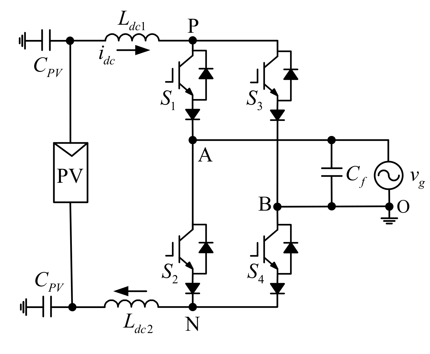
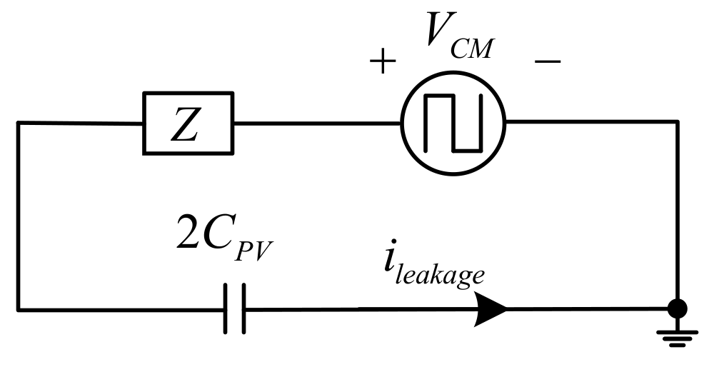
2. Traditional Current Source Inverter

Figure 1 is a schematic of the conventional current-source inverter circuit. Where, Ldc1 and Ldc2 are DC-side inductors, S1S4 are IGBTs (Insulated Gate Bipolar Transistor), Cf is the AC-side filter capacitor, vg is the AC-side voltage, and CPV is the parasitic capacitance between the PV array and the ground. The voltage change across the parasitic capacitance CPV will cause a leakage current, which will affect the grid current.
Figure 1. Conventional current-source inverter.
In order to understand the factors affecting the leakage current, a common-mode loop model, as shown in Figure 2, is established. Where, VCM represents the common-mode voltage (CMV), and Z is the equivalent impedance of the common-mode loop.
V C M = V P O + V N O 2
Z = s L d c 1 L d c 2 L d c 1 + L d c 2
i l e a k a g e = 2 C P V d V C P V d t
V C P V = 1 2 s C P V Z + 1 V C M
where, VCPV represents the voltage across the parasitic capacitance 2CPV. According to Equations (3) and (4),
I l e a k a g e ( s ) = 2 s C P V 2 s C P V Z + 1 V C M
Figure 2. Common-mode model.
According to Equation (2) and Equations (3)–(5), the leakage current Ileakage is dependent on the equivalent common-mode impedance and the rate of the common-mode voltage change. Therefore, reducing the leakage current can be considered from two points, one is to increase the common-mode loop impedance, and the other is to reduce the rate of the common-mode voltage change or to maintain the common-mode voltage constant.
Conventional current-source inverters have four switching states, as shown in Table 1. As shown in Figure 3, the driving signal waveforms of S1 and S3 are changed by low frequency, and the driving signals of S2 and S4 are changed at a high frequency.
Table 1. Current space vectors, switching states and common-mode voltage (CMV).
Figure 3. Gating signals of current-source inverter.
As switch S1 and the switch S4 are turned on, the common-mode voltage can be derived according to Equation (1):
V C M = V P O + V N O 2 = V A O + V B O 2 = v g 2
where, VPO represents the potential of P with respect to O, and VNO represents the potential of N with respect to O.
When the switch S1 and the switch S2 are turned on, the common-mode voltage is:
V C M = V P O + V N O 2 = V A O = v g
As the switch S2 and the switch S3 are turned on, the common-mode voltage is:
V C M = V P O + V N O 2 = V B O + V A O 2 = v g 2
When the switch S3 and the switch S4 are turned on, the common mode voltage is:
V C M = V P O + V N O 2 = V B O = 0
In summary, the switching-frequency common-mode voltage in the system leads to serious leakage current problems of the current-type inverter. In order to effectively suppress the leakage current, this paper will propose a new topology in the next section, which can eliminate the switching common-mode voltage variation for the leakage current attenuation.

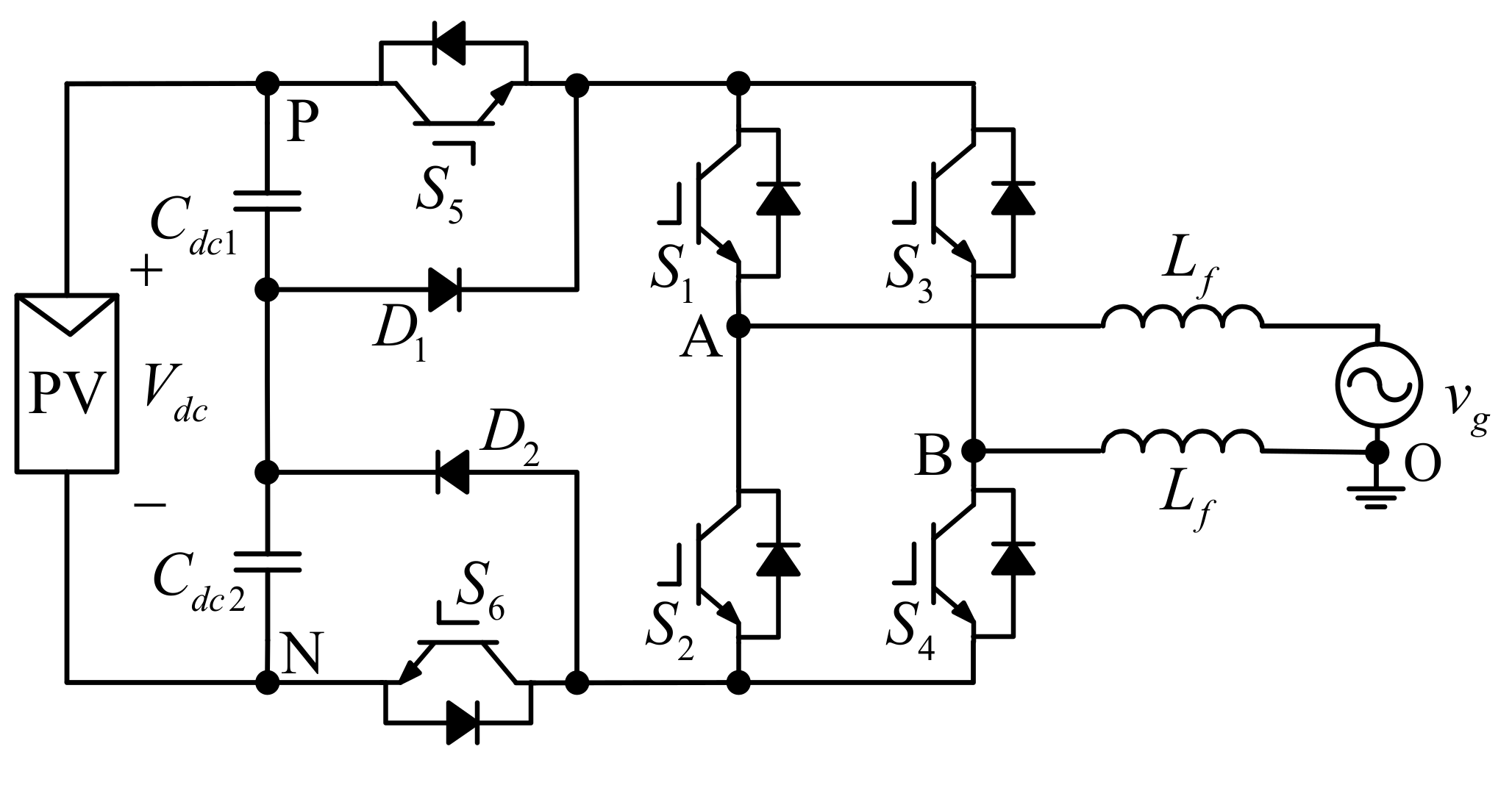
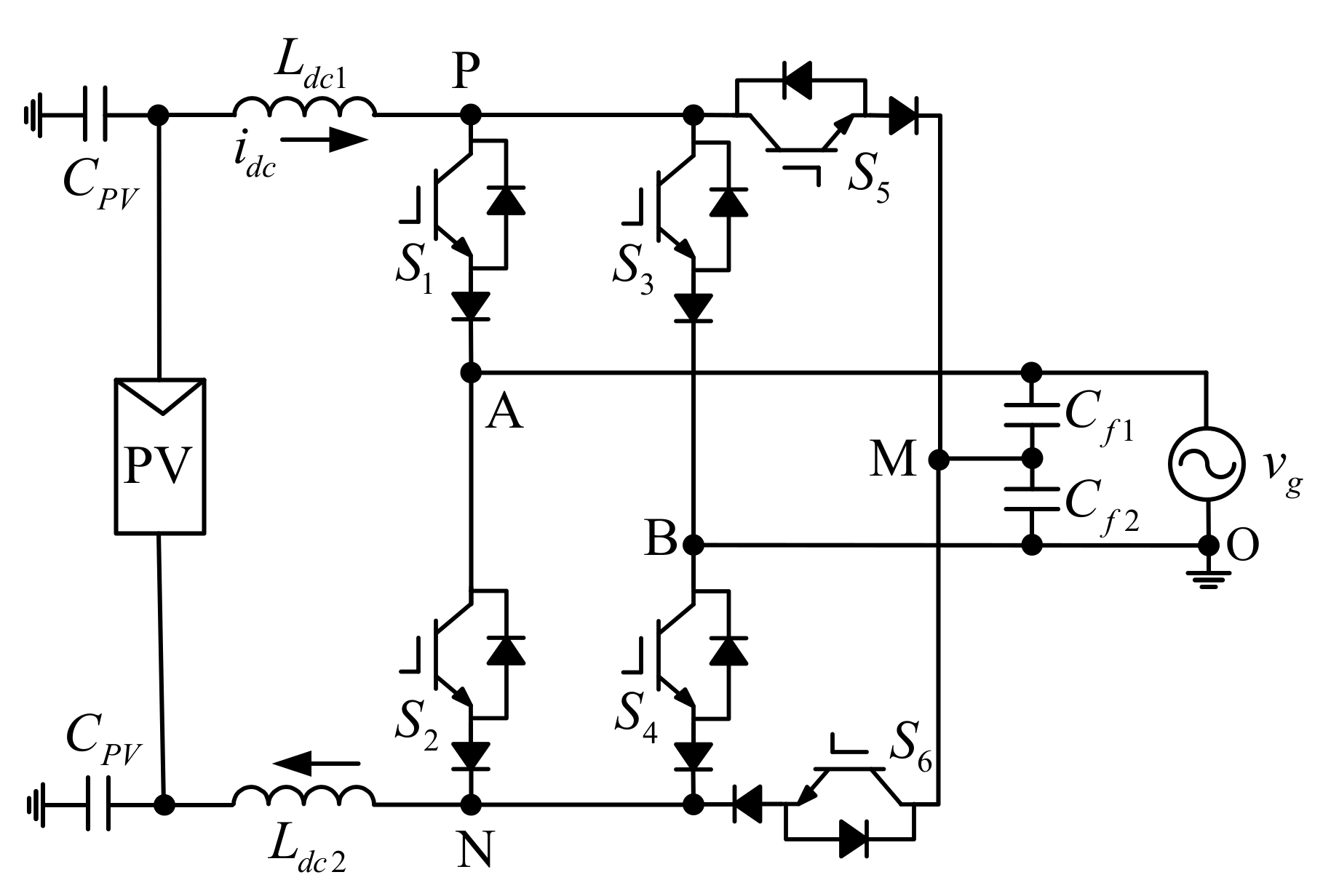
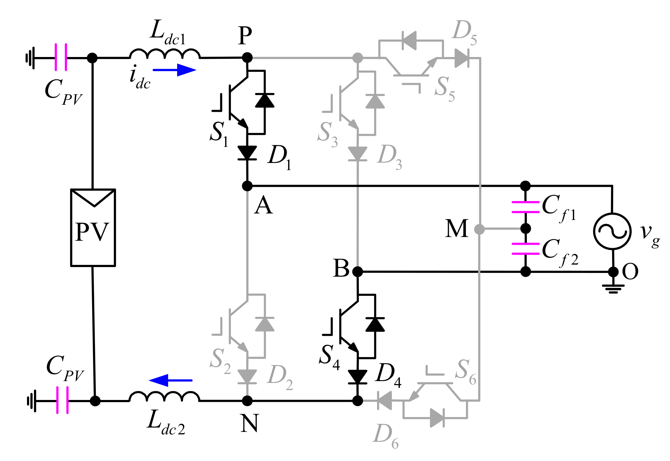
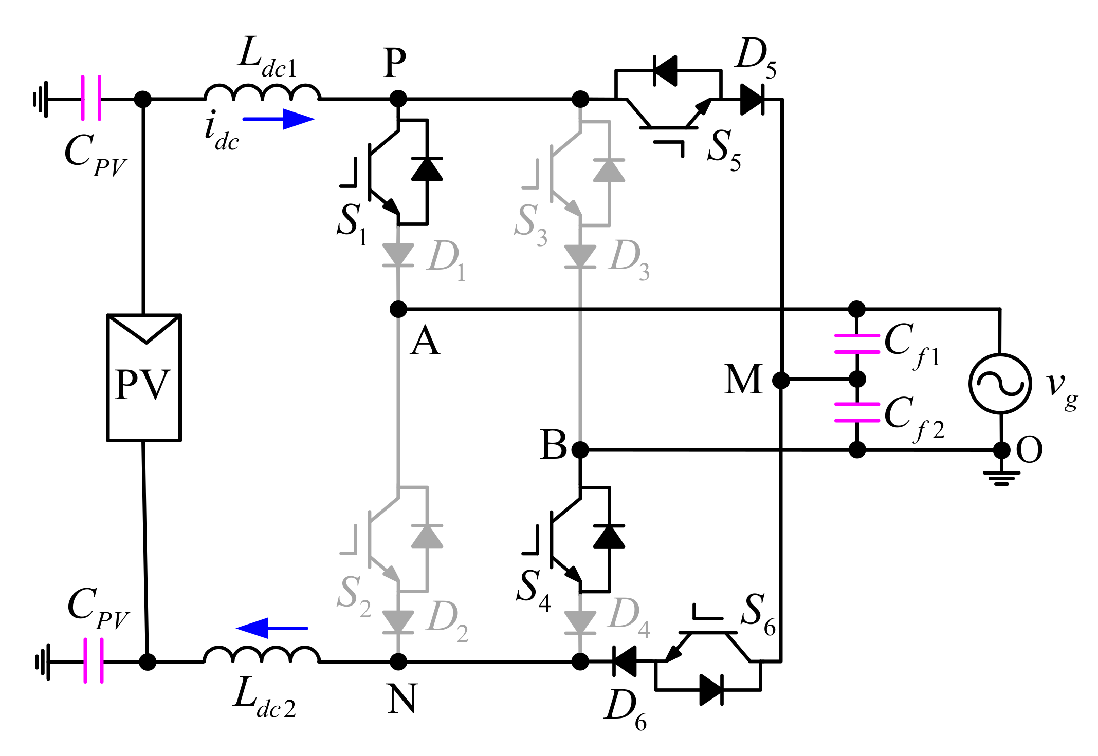
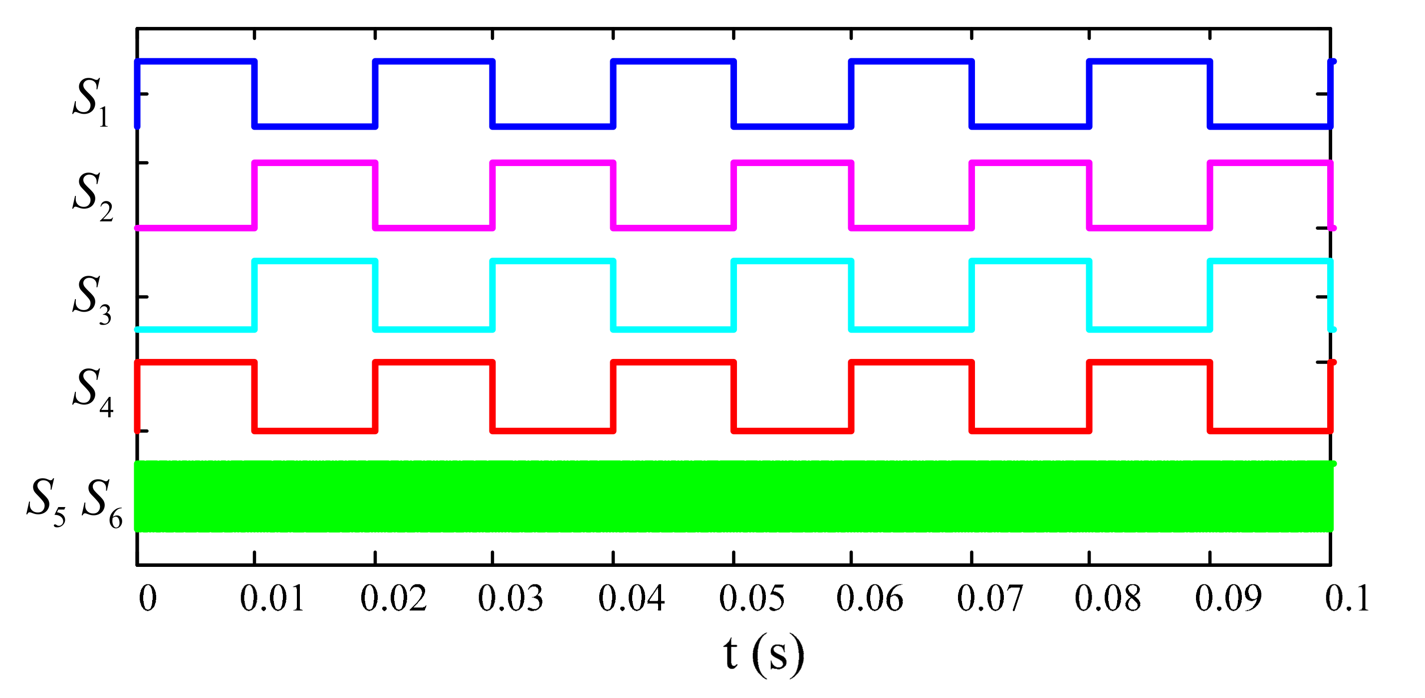
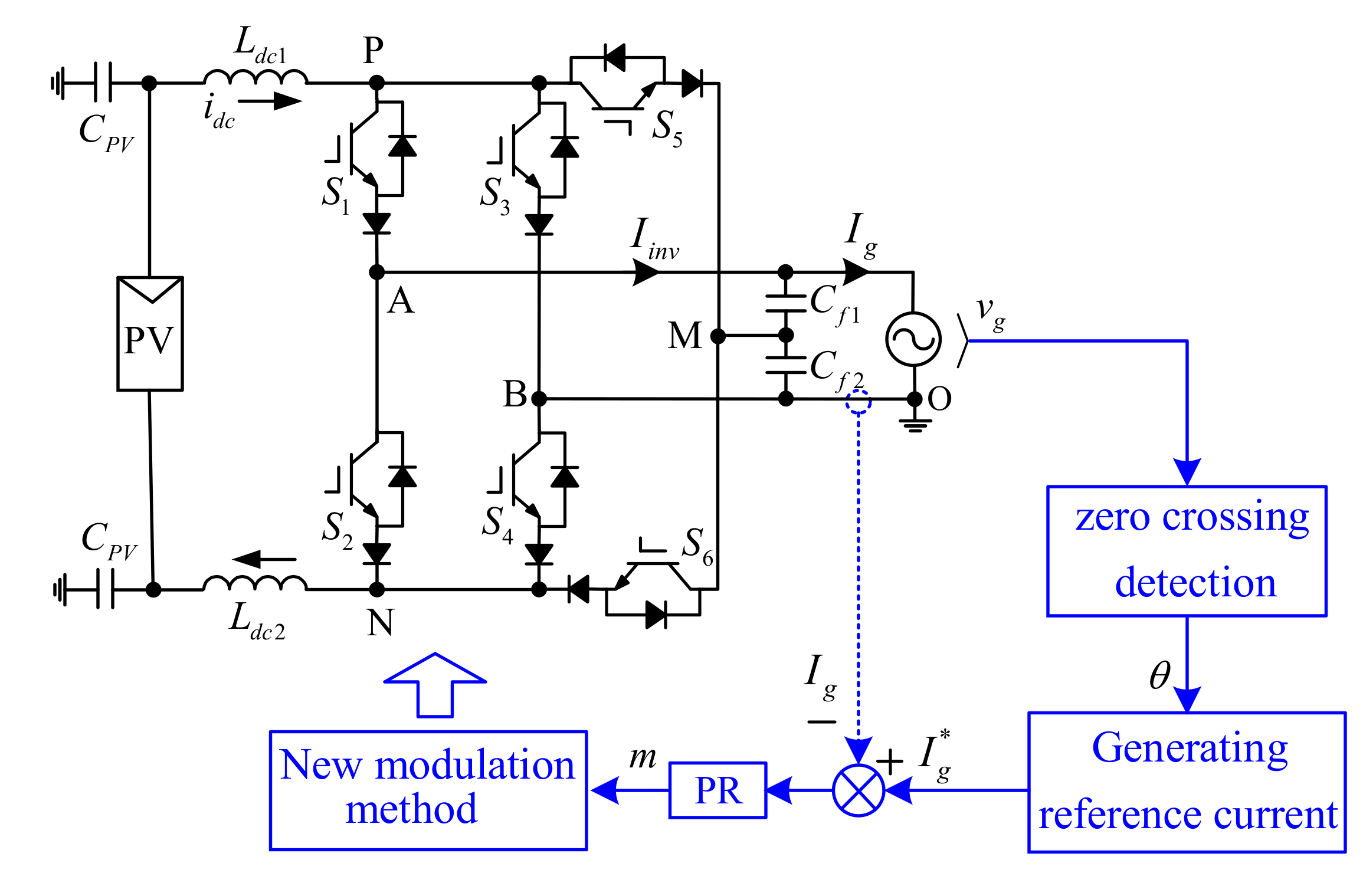
3. New Current-Source Inverter

This section introduces a new current-source inverter topology that can eliminate high-frequency common-mode voltage variation from a topological perspective. As shown in Figure 4, a voltage source DC-bypass inverter is proposed in Reference [23]. It uses the diode to clamp the unchancommon-mode voltage unchanged at Vdc/2, and thus, the leakage current can be suppressed. The corresponding current-type topology is obtained, as illustrated in Figure 5.
Figure 4. Voltage source inverter with DC-side clamping.
Figure 5. New current-source inverter with AC-side clamping.
According to Table 1, the common-mode voltage depends on the grid voltage, and the common-mode voltage variation is from 0 to vg. For eliminating the high-frequency common-mode voltage, the DC-side positive bus P and the negative bus N are clamped at the midpoint of the AC-side filter capacitors during the freewheeling period. According to Equation (1), the common-mode voltage is vg/2 in the freewheeling cycle.
V C M = V P O + V N O 2 = v g 2
During the freewheeling period, the switch S5 and the switch S6 are on to establish a freewheeling path for the DC-side current. The switching states in the active state are the same as that of the conventional current-source inverter. During the half-positive cycle, the switch S1 and the switch S4 are turned on. In the half-negative cycle, the switch S2 and the switch S3 are on. The new current-source inverter switching states and corresponding common-mode voltages are given in Table 2.
Table 2. Current space vectors, switch states and CMV.
It can be seen from Table 2 that the new current-source inverter has three switching states, and the common-mode voltages corresponding to each switching state are the same, which are 0.5vg, and the common-mode voltage frequency is consistent with the fundamental frequency. Since the frequency of the grid voltage vg is smaller than the high switching frequency, the influence of the fundamental-frequency voltage on the switching frequency common-mode characteristics can be ignored. According to Equations (3)–(5), the proposed method eliminates the switching frequency common-mode voltage variation, so that the leakage current is effectively suppressed.
The driving signal waveform of the proposed inverter is shown in Figure 6. The switches S1S6 are high-frequency changes and the switching loss is increased. To solve this problem, a novel modulation method for reducing the switching loss based on the characteristics of the new topology is proposed. Taking the half-positive cycle operating state as an example, the active state I1 and the zero state I0 alternately operate. Figure 7 and Figure 8 are circuit diagrams of the system operating in the active state I1 and the zero state I0, respectively.
Figure 6. Gating signal of new current-source inverter.
Figure 7. Schematic of the active state I1.
Figure 8. Schematic with the active state I0.
According to Figure 8, when the system operates in the zero state, the potential at point A is vg, the potential at point B is 0, the point P and the point N are clamped at point M, and the potential at point M is vg/2. Therefore, in the zero state, if the switch S1 and the switch S4 are in the on state, the diodes D1 and D4 are reversely turned off, and the upper arm and the lower arm are still in the off state, and the circuit is as shown in Figure 9. The switch S1 and the switch S4 can always be in the on state during the half-positive cycle. In a similar manner, for the half-negative cycle, the switch S2 and the switch S3 can always be in the on state. The switching states of the new modulation method can be obtained, as shown in Table 3. Figure 10 shows the gating signals’ waveform when using the new modulation method. It can be seen that the switches S1S4 vary by low frequency, and the switching loss is reduced.
Figure 9. Schematic under new modulation method.
Table 3. Current space vectors, switching states and CMV.
Figure 10. Gating signals with the new modulation.

4. Results

In this section, a system experiment setup was built, and the proposal was compared against the traditional method. The algorithm is realized by the DSP (TMS320F28335) and FPGA (Xilinx XC6SLX9). The experimental parameters are shown in Table 4. Figure 11 shows the control diagram of the proposal. The phase angle θ is detected to generate the reference current. The output m of the PR (Proportional Resonant) regulator is used as the input of the new modulation method. The new modulation method judges the positive or negative of m and selects the corresponding switching sequence. The specific switching sequence selection is shown in Figure 12, where Ts represents the switching period.
Table 4. Experimental parameters.
Figure 11. System control block diagram.
Figure 12. Switching sequence selection for new modulation method.
The experimental results for the conventional current-type inverter are shown in Figure 13. The output current Iinv is unipolar, and the grid current Ig is sinusoidal. Figure 13b shows the voltages VPO, VNO and the common-mode voltage VCM. The leakage current Ileakage waveform is shown in Figure 13c, and the maximum leakage current is 2 A. The switching-frequency variation of the common-mode voltage causes the leakage current to far exceed the 300 mA. As shown in Figure 13d, for the gating signal waveforms of the switches S1S4, the switch S1 and the switch S3 operate at the power frequency, and the switch S2 and the switch S4 operate at a high frequency.
Figure 13. Results with conventional current-type inverter. (a) Output current Iinv, common-mode voltage VCM, grid current Ig; (b) VPO, VNO, common-mode voltage VCM; (c) Leakage current Ileakage, common-mode voltage VCM; (d) Switches S1S4 gating signal waveforms.
The output current Iinv and the grid current Ig are shown in Figure 14a. From Figure 14d, the switches S1-S4 operate in power frequency, which reduces the switching loss. Figure 14b is the experimental result of the voltages VPO, VNO and the common-mode voltage VCM. The common-mode voltage is the half-grid voltage, ignoring the effect of the fundamental-frequency component of the common-mode voltage on the high-frequency common-mode behavior. According to Equation (5), the leakage current is able to be attenuated. The experimental waveform of the leakage current Ileakage is shown in Figure 14c. The maximum value of the leakage current is 144 mA, which meets the standard and is less than 300 mA, which is satisfactory in terms of the VDE-0126-1-1.
Figure 14. Results with new current-source inverter. (a) Output current Iinv, common-mode voltage VCM, grid current Ig; (b) VPO, VNO, common-mode voltage VCM; (c) Leakage current Ileakage, common-mode voltage VCM; (d) Switches S1S6 gating signal waveforms.

5. Conclusions

In this paper, a novel current-source inverter was proposed. Through the principle analysis and experimental research, the following conclusions were drawn. (1) The high-frequency variation of the common-mode voltage of the conventional current-source inverter cannot effectively suppress the leakage current. (2) The topology proposed in this paper can effectively eliminate the high-frequency common-mode voltage of the system, thus effectively suppressing the system leakage current and satisfying the VDE-0126-1-1 standard.

Author Contributions

This paper was a collaborative effort among each of authors.

Funding

This work was supported in part by the Natural Science Foundation of Hebei Province (E2019203563), and the State Key Laboratory of Reliability and Intelligence of Electrical Equipment (EERIKF2018002), Hebei University of Technology.

Conflicts of Interest

The authors declare no conflict of interest.

References

  1. Xiao, G.; Yang, Y.; He, R.; Wang, B.; Blaabjerg, F. Transformerless Z-source four-leg PV inverter with leakage current reduction. IEEE Trans. Power Electron. 2019, 34, 4343–4352. [Google Scholar]
  2. Ji, Y.; Yang, Y.; Zhou, J.; Ding, H.; Guo, X.; Padmanaban, S. Control strategies of mitigating dead-time effect on power converters: An overview. Electronics 2019, 8, 196. [Google Scholar] [CrossRef]
  3. Siwakoti, Y.P.; Blaabjerg, F. Common-ground-type transformerless inverters for single-phase solar photovoltaic systems. IEEE Trans. Ind. Electron. 2018, 65, 2100–2111. [Google Scholar] [CrossRef]
  4. Rojas, C.A.; Aguirre, M.; Kouro, S.; Geyer, T.; Gutierrez, E. Leakage current mitigation in photovoltaic string inverter using predictive control with fixed average switching frequency. IEEE Trans. Ind. Electron. 2017, 64, 9344–9354. [Google Scholar] [CrossRef]
  5. Freddy, T.K.S.; Rahim, N.A.; Hew, W.; Che, H.S. Comparison and analysis of single-phase transformerless grid-connected PV inverters. IEEE Trans. Power Electron. 2014, 29, 5358–5369. [Google Scholar] [CrossRef]
  6. Zeng, H.; Li, Y.; Zhang, B.; Zheng, T.Q.; Hao, R.; Yang, Z. An improved H5 topology with low common-mode current for transformerless PV grid-connected inverter. IEEE Trans. Power Electron. 2019, 34, 1254–1265. [Google Scholar]
  7. Kafle, Y.R.; Town, G.E.; Guochun, X.; Gautam, S. Performance comparison of single-phase transformerless PV inverter systems. In Proceedings of the 2017 IEEE Applied Power Electronics Conference and Exposition (APEC), Tampa, FL, USA, 26–30 March 2017. [Google Scholar]
  8. Xiao, G.; Jia, X. Hardware-based cascaded topology and modulation strategy with leakage current reduction for transformerless PV systems. IEEE Trans. Ind. Electron. 2016, 62, 7823–7832. [Google Scholar]
  9. Yang, B.; Li, W.; Gu, Y.; Cui, W.; He, X. Improved transformerless inverter with common-mode leakage current elimination for a photovoltaic grid-connected power system. IEEE Trans. Power Electron. 2012, 27, 752–762. [Google Scholar] [CrossRef]
  10. Guo, X.; Yang, Y.; Zhu, T. ESI: A novel three-phase inverter with leakage current attenuation for transformerless PV systems. IEEE Trans. Ind. Electron. 2018, 65, 2967–2974. [Google Scholar] [CrossRef]
  11. Zhang, L.; Sun, K.; Xing, Y.; Xing, M. H6 transformerless full-bridge PV grid-tied inverters. IEEE Trans. Power Electron. 2014, 29, 1229–1238. [Google Scholar] [CrossRef]
  12. Dai, H.; Jahns, T.; Torres, R.; Han, D.; Sarlioglu, B. Comparative evaluation of conducted common-mode EMI in voltage-source and current-source inverters using wide-bandgap switches. In Proceedings of the IEEE Transportation Electrification Conference and Expo, Long Beach, CA, USA, 13–15 June 2018. [Google Scholar]
  13. Dai, H.; Jahns, T.M. Comparative investigation of PWM current source inverters for future machine drives using high-frequency wide-bandgap power switches. In Proceedings of the IEEE Applied Power Electronics Conference, San Antonio, TX, USA, 4–8 March 2018. [Google Scholar]
  14. Dai, H.; Jahns, T.; Torres, R.; Liu, M.; Sarlioglu, B.; Chang, S. Development of high-frequency WBG power modules with reverse-voltage-blocking capability for an integrated motor drive using a current-source inverter. In Proceedings of the IEEE Energy Conversion Congress and Exposition, Portland, OR, USA, 23–27 September 2018. [Google Scholar]
  15. Torres, R.A.; Dai, H.; Lee, W.; Jahns, T.M.; Sarlioglu, B. Current-source inverters for integrated motor drives using wide-bandgap power switches. In Proceedings of the 2018 IEEE Transportation Electrification Conference and Expo, Long Beach, CA, USA, 13–15 June 2018. [Google Scholar]
  16. Chen, Y.; Smedley, K. Three-phase boost-type grid-connected inverter. IEEE Trans. Power Electron. 2008, 23, 2301–2309. [Google Scholar] [CrossRef]
  17. Dash, P.P.; Kazerani, M. Dynamic modeling and performance analysis of a grid-connected current-source inverter-based photovoltaic system. IEEE Trans. Sustain. Energy 2011, 2, 443–450. [Google Scholar] [CrossRef]
  18. Wang, Z.; Zou, Z.; Zheng, Y. Design and control of a photovoltaic energy and SMES hybrid system with current-source grid inverter. IEEE Trans. Appl. Supercond. 2013, 23, 5701505. [Google Scholar] [CrossRef]
  19. Anand, S.; Gundlapalli, S.K.; Fernandes, B.G. Transformer-less grid feeding current source inverter for solar photovoltaic system. IEEE Trans. Ind. Electron. 2014, 61, 5334–5344. [Google Scholar] [CrossRef]
  20. Barbosa, G.; Braga, C.; Rodrigues, B.; Teixeira, E. Boost current multilevel inverter and its application on single-phase grid-connected photovoltaic systems. IEEE Trans. Power Electron. 2006, 21, 1116–1124. [Google Scholar] [CrossRef]
  21. Noguchi, T. A new three-level current source PWM inverter and its application for grid connected power conditioner. Energy Convers. Manag. 2010, 51, 1491–1499. [Google Scholar]
  22. Garcia, L.S.; Buiatt, G.M.; de Freitas, L.C.; Coelho, E.; Farias, V.J.; de Freitas, L.C.G. Dual transformerless single-stage current source inverter with energy management control strategy. IEEE Trans. Power Electron. 2013, 28, 4644–4656. [Google Scholar] [CrossRef]
  23. Gonzalez, R.; Lopez, J.; Sanchis, P.; Marroyo, L. Transformerless inverter for single-phase photovoltaic systems. IEEE Trans. Power Electron. 2007, 22, 693–697. [Google Scholar] [CrossRef]

Article Metrics

Citations

Article Access Statistics

Multiple requests from the same IP address are counted as one view.