Article

Design and Performance Analysis of a Single-Phase BLDC Motor

Department of Electrical Electronics Engineering, Fırat University, Elazig 23119, Turkey
*
Author to whom correspondence should be addressed.
Electronics 2026, 15(3), 683; https://doi.org/10.3390/electronics15030683
Submission received: 23 December 2025 / Revised: 29 January 2026 / Accepted: 2 February 2026 / Published: 4 February 2026

Abstract

In today’s world, the demand for compact, high-efficiency, and low-cost motors plays a significant role in the design of low-power electric machines. In combi fan applications, single-phase brushless direct current (BLDC) motors are generally preferred. Although these motors offer efficient and compact solutions, the occurrence of dead points at certain rotor positions creates a serious disadvantage that may prevent the motor from initiating motion. In this study, an asymmetric air gap design is proposed for a single-phase BLDC motor to eliminate the dead point problem and increase starting torque. The motor’s performance has been evaluated through analytical calculations and two-dimensional finite element analysis (FEA) conducted using ANSYS Electronics Desktop 2020 R2 (Maxwell) software. The results show that the asymmetric air gap effectively eliminates the dead point and improves the motor’s starting performance. However, torque ripple is still identified as a design parameter that must be considered. The scope of this study is not limited to single-phase BLDC motors; it also provides analytical approaches that can be applied to different electric motor designs, contributing to engineering applications in this field.

1. Introduction

In recent years, the growing demand for low-power electric motors has necessitated the development of compact, efficient, and cost-effective solutions across various industrial and consumer electronics applications. In particular, combi fan motors are commonly designed using single-phase brushless direct current (BLDC) motors due to their advantages such as continuous operation capability, long lifespan, and low maintenance requirements. Single-phase BLDC motors are widely employed in low-power applications owing to their simple structure, ease of manufacturing, and low cost [1,2]. These motors, which are generally known for their low starting torque, are preferred in low-power applications such as fuel pumps, cooling system fans, air conditioner compressor motors, and PC cooling fans [3,4]. Although they exhibit lower efficiency and longer response times compared to three-phase BLDC motors, their cost-effectiveness and suitability for mass production offer significant advantages. They are typically used in systems requiring output power up to 100 W [5,6].
In today’s competitive landscape, BLDC motors have become a preferred choice for many applications due to their advantages such as high power density, simple driver circuitry, and high efficiency. However, there are certain gaps in the existing literature and research related to BLDC motors [7,8]. Single-phase BLDC motors stand out due to their compact size, high reliability, absence of carbon dust resulting from brush wear, precise speed control, and potentially high efficiency [9,10]. Single-phase BLDC motors exhibit zero torque points at specific rotor positions [11]. These points are referred to as “dead points.” To prevent the rotor from stopping at a dead point, there must not be a uniform air gap beneath the stator poles. Otherwise, if the rotor settles at a dead point, restarting the motor may become impossible. In order to eliminate the zero torque region and ensure starting torque in these motors, the adoption of an asymmetric air gap design, capable of generating a reluctance torque component, is necessary [12,13]. However, this design results in the motor operating in only a single direction. The unidirectional operation of the motor provides a significant advantage in fan applications, as it ensures a consistent airflow in a single direction. On the other hand, under open-loop pulse-width modulation (PWM) control, a current spike occurs during each commutation event, leading to disadvantages such as acoustic noise, increased electronic cost, torque pulsations, and reduced efficiency [14].
In single-phase BLDC motors, a symmetric air gap produces a uniform reluctance distribution, leading to a balanced cogging torque but failing to generate starting torque at dead points. The introduction of an asymmetric air gap is a deliberate design choice to alter the reluctance variation. While this modification is essential for shifting the zero-torque points to enable self-starting, it inherently affects the cogging torque profile and amplitude, often necessitating a trade-off between starting capability and torque ripple.
The design of electrical machines is a multidisciplinary process that requires the simultaneous evaluation of electromagnetic, thermal, mechanical, and economic parameters. In this process, a balanced approach should be adopted not only focusing on performance but also considering cost, reliability, and sustainability criteria. In this context, interdisciplinary integration and multi-objective optimization techniques constitute the foundation of contemporary design practices.
The starting point of the design process is the clear definition of the target application. For example, in electric vehicles, in line with the expectations of high torque density and energy efficiency, optimizing the rotor geometry by considering both drive and regenerative braking scenarios becomes a critical requirement [15]. In such applications, ensuring balanced electromechanical performance under varying load conditions is important for system reliability and efficiency.
The selection of the motor topology is a fundamental decision that determines the direction of the entire design process. The advantages of different architectures, such as surface-mounted permanent magnet synchronous motors, switched reluctance motors, and axial flux machines, should be evaluated based on the specific application. Especially in complex drive cycles, identifying target points instead of analyzing numerous operating points and performing optimization via genetic algorithms reduces computation time and increases solution accuracy [16].
In the electromagnetic design phase, variables such as the number of poles, slot geometry, magnet arrangement, and winding configuration have a direct impact on torque production and losses. Studies in the literature reveal that the contribution of reluctance torque is particularly limited, thereby emphasizing the decisive role of rotor geometry [17]. In addition, thermal analysis is an indispensable design parameter in terms of system safety. The high heat density generated in compact motor structures makes temperature control especially challenging in the end-winding region. Therefore, accurately predicting the temperature distribution using detailed 3D thermal modeling enables the development of effective cooling solutions [18].
Mechanical analyses aim to address potential vibration and durability issues in high-speed motors. To improve Noise, Vibration, and Harshness (NVH) performance, the rotor structure must be optimized according to its natural frequencies [19]. The integrated consideration of these interdisciplinary models enables system-level optimization. For example, by simultaneously analyzing electromagnetic, thermal, and mechanical effects, a rotor structure can be optimized in terms of both torque efficiency and thermal endurance [20]. In these complex design processes, multi-objective genetic algorithms are commonly preferred to balance conflicting performance targets. Through these methods, it is possible to achieve Pareto-optimal solutions between efficiency, power density, and cost [21]. Moreover, some studies have implemented constraint management using customized repair operators to reduce computational cost and improve solution quality [22].
The validation of the design should be conducted not only in simulation environments but also through physical prototypes and experimental tests. Achieving high agreement between simulation outputs and experimental results reinforces the reliability of the employed modeling approaches [23]. Additionally, economic evaluation represents an important dimension of the design process. Especially in the cost-sensitive automotive sector, analyzing performance sustainability under different material scenarios and adopting modular manufacturing strategies are common practices [24,25]. The robustness of the design can be improved by examining the impact of manufacturing tolerances on performance [26]. Nowadays, considering environmental impacts has also become an integral part of the electrical machine design process. Through life cycle assessments, not only the efficiency but also the environmental sustainability of the motor can be evaluated [27].
In this study, the design of a single-phase BLDC motor used in combi fan applications is addressed through the implementation of an asymmetric air gap design, and both analytical calculations and ANSYS Maxwell 2D simulation results are examined. The study provides a detailed evaluation of the design process and analytical modeling of the single-phase BLDC motor. Although the literature includes various optimization studies focused on the development of BLDC motors and enhancement of output parameters, a fully comprehensive design study has not been encountered based on the conducted research. This study aims to establish a foundation for future work by presenting the technical details, analytical calculations, and simulation results related to BLDC motor design.
The remainder of this study is structured as follows: Section 2 details the motor design process, the methods employed, and the analytical calculations. Section 3 presents the simulation results, while Section 4 provides a general evaluation of the study and offers recommendations for future research.

2. Materials and Methods

While BLDC motors are typically designed with a three-phase configuration, single-phase BLDC motors are preferred in certain applications due to their lower cost and simpler driver circuitry requirements. Compared to their three-phase counterparts, single-phase BLDC motors offer advantages such as requiring fewer components, having a more compact design, and being more suitable for mass production. However, these motors also have drawbacks, including low starting torque and a tendency to create dead points at specific rotor positions. Therefore, factors such as the magnetic air gap, commutation strategies, and torque performance are critically important in the design of these motors.
In this study, the design process of a single-phase BLDC motor used in combi fan applications is addressed, and the proposed design is evaluated in terms of how it resolves the dead point issue and its impact on overall motor performance.

2.1. Structure and Operating Principle of the Single-Phase BLDC Motor

A single-phase BLDC motor is an electric machine equipped with permanent magnets on the rotor and utilizes electronic commutation instead of the mechanical commutator and brush system used in conventional brushed DC motors [28]. In order for the rotor to rotate, a rotating magnetic field must be generated within the motor [29]. To generate this rotating magnetic field, the direction of current must be periodically altered in accordance with the position of the magnets on the rotor. Therefore, single-phase BLDC motors require a driver circuit.
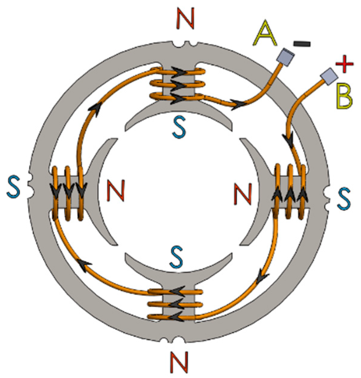
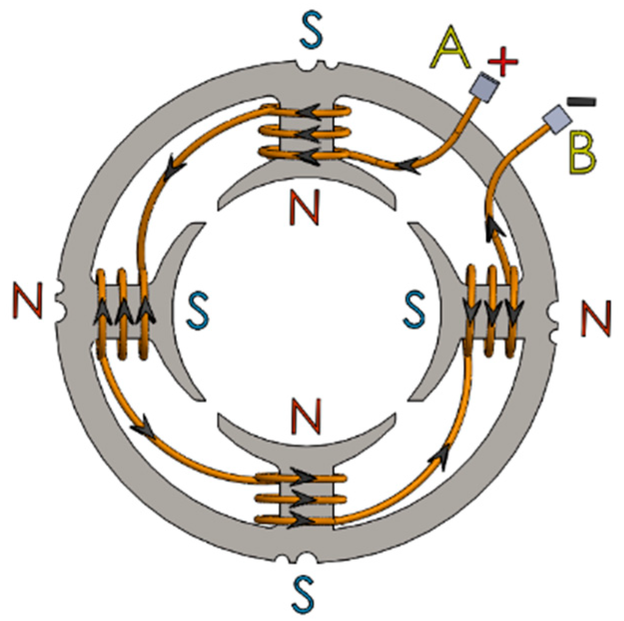
The stator structure of the single-phase, four-pole brushless DC motor is presented in Figure 1 and Figure 2. The stator consists of four coils wound using the concentrated winding technique, where each coil forms a magnetic pole, resulting in an overall four-pole magnetic field configuration.
The coils are connected in series. Although the current direction is identical in all windings due to the series connection, the winding directions of successive coils are arranged oppositely in order to obtain the desired alternating magnetic pole sequence around the stator periphery. As a result, an N–S–N–S magnetic pole distribution is established along the stator. The orientation of the magnetic poles is determined based on the conventional right-hand rule, which defines the relationship between the current direction and the resulting magnetic field.
Figure 1 illustrates the winding directions of the coils and the corresponding spatial distribution of the magnetic poles on the stator. As shown in Figure 2, reversing the direction of the current flowing through the coils leads to a reversal of the stator magnetic field, causing an interchange of the north (N) and south (S) pole positions. When the current direction is periodically reversed at a certain frequency, a spatially time-varying magnetic pole pattern is produced within the stator, giving rise to a rotating magnetic field. The interaction between this rotating magnetic field and the rotor generates electromagnetic torque, thereby enabling the rotational motion of the motor.
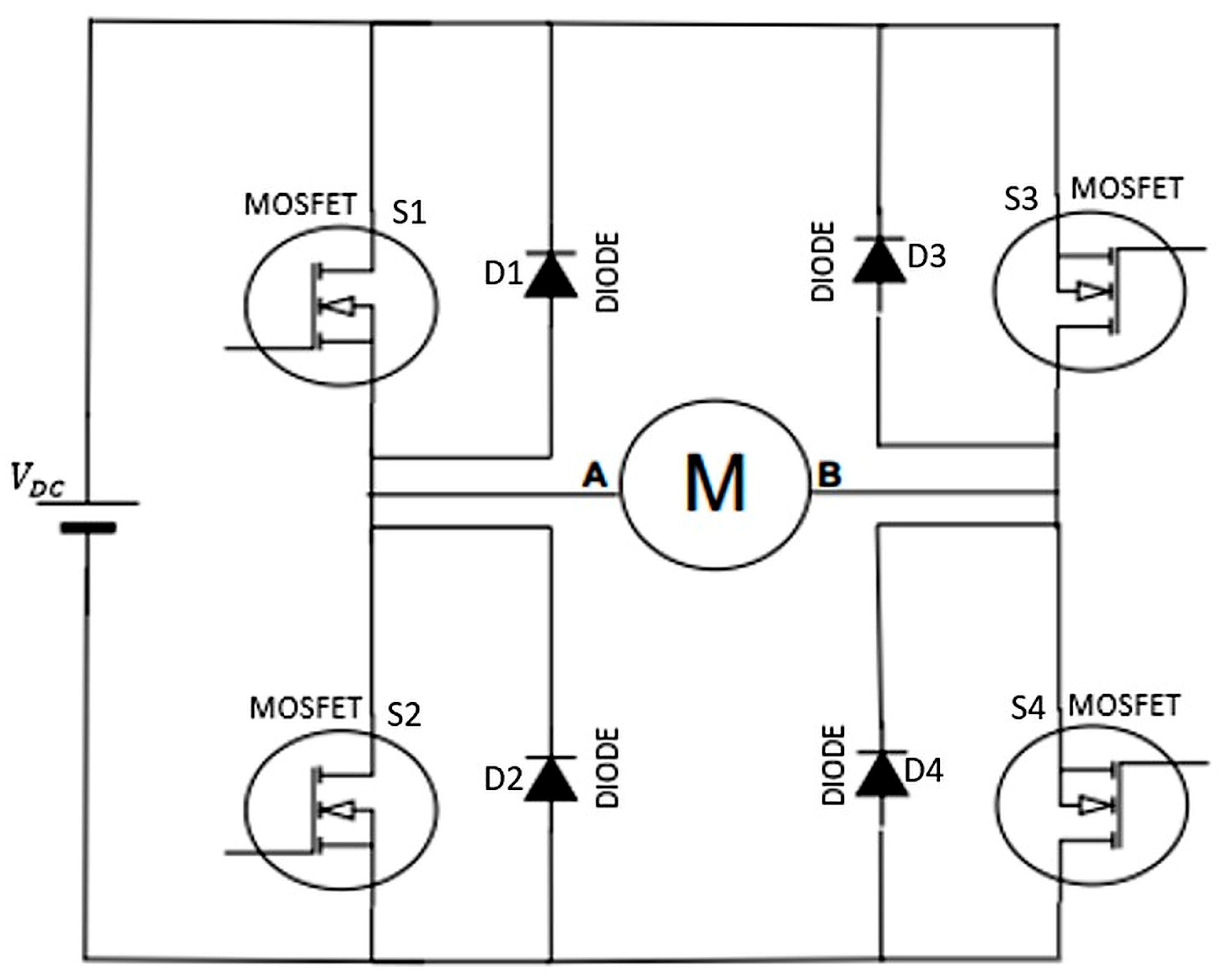
The H-bridge inverter illustrated in Figure 3 is composed of four power MOSFET switches (S1–S4) along with their antiparallel freewheeling diodes (D1–D4). The switches S1–S4 regulate the direction of the current flowing through the motor winding, thereby controlling the magnetic field established within the motor, which is required for electronic commutation in the single-phase BLDC motor. During operation, diagonal switch pairs (S1–S4 or S2–S3) are turned on to reverse the current direction in the phase winding.
The antiparallel diodes D1–D4 provide a freewheeling path for the inductive winding current when the MOSFETs are turned off. This prevents excessive voltage spikes caused by the winding inductance and ensures safe and reliable operation of the power electronic converter.
Based on the rotor position information obtained from the Hall-effect sensor, current is applied to the motor winding through terminal A or B by means of the single-phase H-bridge circuit shown in Figure 3. The single-phase BLDC motor is driven using this full-bridge inverter configuration [30]. Depending on the rotor position, the direction of the current flowing through the H-bridge is reversed, thereby generating a continuously and periodically repeating rotating magnetic field within the stator, as illustrated in Figure 1 and Figure 2.
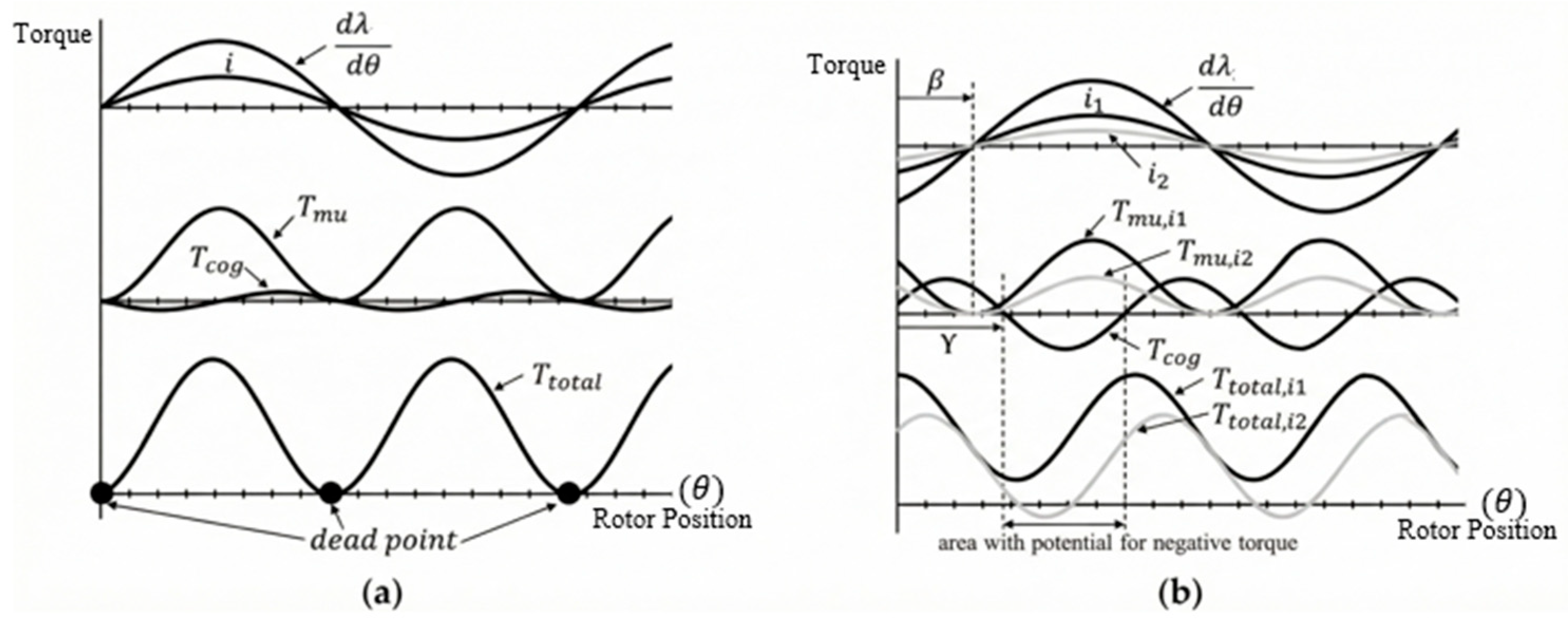
In Figure 4a, the dead points occurring in a single-phase BLDC motor with a symmetric air gap are shown. In Figure 4b, it is observed that the dead point issue is eliminated by applying an asymmetric air gap [8]. Although the use of an asymmetric air gap can eliminate dead points, it adversely affects the torque and efficiency characteristics of the motor [11].
T total = T mu + T cog  
In Equation (1), T m u is mutual torque, T c o g   is cogging torque, and T t o t a l   is total torque.
T mu = i d λ d θ = i λ sin θ β  
In Equation (2), i   is current, β   is mutual torque phase angle, angle, θ is position of rotor and λ is flux linkage.
T cog = 1 2 ϕ m 2 dR d θ = T ^ cog sin { 2 θ γ }  
In Equation (3), ϕ m   is magnetic flux, R   is reluctance and γ   is cogging torque phase. Here, T ^ c o g denotes the amplitude of the cogging torque.
Equations (1)–(3) are adapted from [8]. The torque production mechanism of the single-phase BLDC motor is mathematically modeled by Equations (1)–(3). Equation (1) expresses the total instantaneous torque as the superposition of two distinct mechanisms: the active mutual torque, generated by the interaction of current and magnetic flux, and the passive cogging torque, arising from the magnet-iron interaction. The mutual torque, defined in Equation (2), governs the motor’s power output and is directly proportional to the stator current and the spatial rate of change of the flux linkage. Physically, this relationship implies that torque production is maximized when current injection is synchronized with the peak back-EMF. In the context of the proposed asymmetric design, the phase angle β is particularly significant as it represents the shift in the effective flux axis caused by the non-uniform air gap. Finally, Equation (3) characterizes the cogging torque, derived from the principle of minimum reluctance. The dependence on dR/dθ indicates that this torque component exists solely due to the variation of magnetic reluctance with respect to rotor position. By intentionally modifying this reluctance gradient and the resulting phase angle γ through the asymmetric air gap, a specific ‘detent’ torque is created to prevent the rotor from aligning with magnetic dead points when unpowered.
Equation (1) expresses the total electromagnetic torque as the sum of the cogging torque and mutual torque. Equation (2) provides the mutual torque’s mathematical expression. The phase angle γ changes more than the phase angle β due to the reluctance effect caused by the asymmetric air gap variation, as seen in Figure 4b. This is due to the fact that the rate of change of reluctance with respect to rotor position has a more direct impact on the phase angle γ, as demonstrated by Equation (3). As shown in Figure 4b, a phase shift between the mutual torque and the cogging torque results from variations in the phase angles γ and β [8].
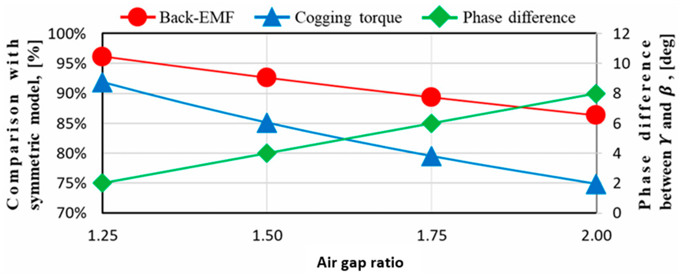
Hongsik Hwang et al. studied the “No-load performance of the conical air gap as a function of length ratio” and obtained the results shown in Figure 5 [8]. According to the analysis results, it has been found appropriate to set the air gap ratio to approximately two-to-one [31].
The relationship between the total electromagnetic torque ( T t o t a l ) defined in Equation (1) and the mechanical output torque ( T o u t ) used in the design equations requires clarification. The total electromagnetic torque ( T t o t a l ) represents the instantaneous torque produced by the motor, which consists of two components: the mutual torque ( T m u ) arising from the interaction between the stator current and rotor magnetic field, and the cogging torque ( T c o g ) resulting from the variation of magnetic reluctance with rotor position.
The output torque ( T o u t ) represents the average useful mechanical torque delivered to the load. Under steady-state operating conditions, the relationship between these quantities can be expressed as:
T out   =   T avg     T loss  
where T a v g is the time-averaged value of T t o t a l over one electrical cycle, and T l o s s accounts for friction and windage losses. Since the cogging torque ( T c o g ) is a pulsating component with zero average value over a complete electrical cycle, the average output torque primarily depends on the average mutual torque component. Therefore:
T a v g = 1 T 0 T T t o t a l . d t T m u , a v g  
In practical motor design, when T l o s s is negligible compared to T a v g (typically less than 5% for small motors), the output torque T o u t closely approximates the average total electromagnetic torque. This relationship justifies the use of T o u t in the design equations (Equations (4)) as the target mechanical output, while T t o t a l (Equation (1)) describes the instantaneous electromagnetic behavior including torque ripple effects.

2.2. Single-Phase BLDC Motor Design

In this study, the combi fan motor is designed to operate at approximately 7200 rpm under a 300 V DC supply, delivering an output power of 95 W and average torque of 0.095 Nm. Within the scope of the study, the step-by-step design process of the single-phase BLDC motor is presented, and the obtained results are compared with ANSYS Maxwell analysis outcomes.
P o u t = T o u t ω m  
ω m = 2 π r p s  
r p s = r p m 60  
P i n = P o u t η d  
V r m s = V D C V d r o p 2  
i r m s = P i n V r m s  
Here P o u t is output power, T o u t is output torque, ω m is angular velocity, rps is revolutions per second, rpm is revolutions per minute, P i n is input power, η d is target efficiency, V r m s is effective voltage value, V D C is DC voltage value, V d r o p is voltage drop value, i r m s is effective current value. The design process begins by defining the mechanical load requirements imposed by the combi fan application. Equations (6)–(8) determine the required mechanical shaft power based on the target output torque and angular velocity, where the rotational speed is converted to radians per second to ensure unit consistency. Subsequently, Equation (9) estimates the required electrical input power, utilizing the target efficiency as a critical design parameter to account for the anticipated copper, iron, and friction losses. Since the motor is driven by a single-phase H-bridge inverter, the voltage applied to the windings alternates polarity. Therefore, Equation (10) is employed to calculate the effective (RMS) voltage available for torque production; this calculation explicitly considers the voltage drop across the power switches and adjusts the DC bus voltage by a factor of 2 to represent the fundamental component of the applied square-wave voltage. Finally, Equation (11) derives the effective phase current. This parameter physically represents the thermal load on the stator windings and dictates the selection of the conductor wire gauge to ensure safe operation within thermal limits.
In Equation (6), the formulas for calculating the motor’s output power are provided. Using this equation, both the torque value and the motor output coefficient are determined. Equations (7) and (8) present the method for calculating the angular velocity ( ω m ) in radians, where the rotational speed given in revolutions per minute (rpm) is first converted into revolutions per second (rps) by dividing by 60, and the angular velocity is then obtained by multiplying the resulting value by 2π. Prior to starting the design process, once the target efficiency is defined, the input power is calculated using Equation (9).
In order to determine the motor current, the input power must first be calculated, and the voltage level to be applied to the motor must be predetermined. During the current calculation, voltage drops that may occur in the circuit should be taken into account, and these drops should be included in the calculations within reasonable limits. Depending on the structural characteristics of the motor, the effective value of the applied voltage may vary. Particularly in the design of single-phase brushless direct current (BLDC) motors, the applied DC voltage is supplied in the form of positive and negative alternations that change over time according to the rotor position. This means that the effect of the steady DC component must be discounted in the RMS voltage calculation. Therefore, in such motors, when calculating the RMS value of the voltage, it is assumed that the applied DC voltage level is reduced by a factor of √2 and this reduction is incorporated into the calculation [32]. In line with this approach, the RMS current of the motor can be calculated using Equations (10) and (11).
E p h = d λ d t = d λ d θ e d θ e d t = d λ d θ e ω e = d λ d θ e ω m N m 2
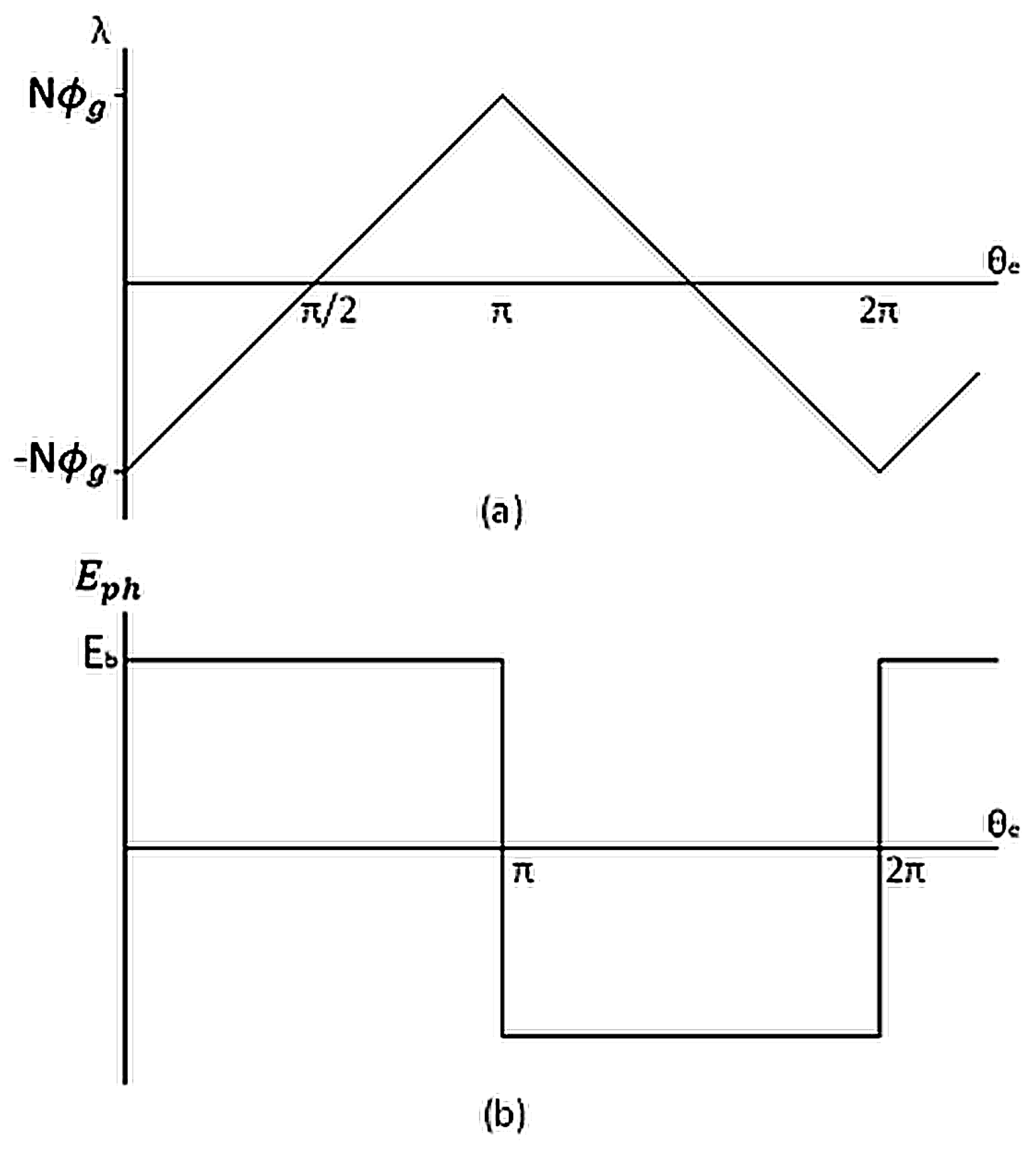
As can be seen from Figure 6a, the expression λ θ e can be represented by a straight-line equation of the form λ θ e = A θ e + B In this equation, the constant term is defined as B = N ϕ g while the A coefficient is given by A = 2 N ϕ g / π . Substituting these coefficients into the flux linkage expression yields λ θ e =   2 . N . ϕ g π θ e N ϕ g Taking the time derivative of this expression gives d λ θ e d θ e = 2 N ϕ g π d θ e d t here, d θ e d t = ω e , where the electrical angular speed is defined as ω e = ω m N m 2 . In addition, the maximum flux linkage is defined as λ m a x = N ϕ g . Accordingly, the back electromotive force ( E p h ) can be expressed as given in Equation (13).
  E p h = 2 λ m a x π ω m N m 2  
λ max = k w N t p h φ p
According to Faraday’s law, the back-EMF corresponds to the derivative of the flux linkage waveform. As shown in Figure 6a, since the flux linkage waveform is triangular, the resulting back-EMF waveform, as illustrated in Figure 6b, takes the form of a square wave [33]. Analytically, the back-EMF is expressed in Equation (12). The symbols used in this equation represent the following: λ denotes the flux linkage, ω e the electrical angular velocity, ωₘ the mechanical angular velocity, and N m represents the number of rotor poles. Therefore, based on the linear variation of the flux linkage observed in Figure 6a, an analytical expression of the flux linkage as a function of the electrical angle is defined. This linear characteristic of the flux linkage waveform indicates that the magnitude of the back electromotive force is directly related to the slope of the waveform. Within the framework of Faraday’s law, the time derivative of this linear flux linkage expression is taken to obtain the phase back-EMF expression, which is presented in Equation (13). The flux linkage expression is given in Equation (14), where k W , Nₜₚₕ, and φₚ represent the winding factor, the number of phase effective turns, and the pole flux. Finally, by incorporating the slope factor ( k s ) into the equation, the final form of Equation (15) is obtained.
E p h = 2 λ m a x π ω m N m 2 k s  
The physical and magnetic characteristics of the magnetic sheets used in the design of electrical machines are among the fundamental factors that directly affect machine performance. In permanent magnet motors in particular, the magnetic flux density in the air gap is assumed to be a constant value based on the flux density of the magnet material, its magnetic saturation level, and the magnetization properties of the magnetic sheet used. This constant value is employed as a reference parameter in the calculations and is considered a key input in the electromagnetic design of the motor. Numerous experimental studies and performance analyses in the literature have identified appropriate ranges of magnetic flux density recommended for different motor types. These ranges can serve as initial references for similar designs. The expression for calculating the average absolute magnetic flux density in the air gap ( B a v ) is given by Equation (16), where D represents the inner diameter of the stator and L denotes the length of the magnetic core (stack). When the pole flux ( φ p ) used in the formula is rearranged using Equation (13), the result is expressed in Equation (17). When the obtained equation is substituted into Equation (15), Equation (18) is obtained.
B a v = φ p N m π D L
λ max = k w N tph B av π DL N m  
E ph = k w k s N tph B av π DL 2 rps  
Electric loading, that is, the linear current density around the (ac) air gap, is defined as the number of ampere-conductors per meter along the stator surface facing the air gap. The mathematical expression of this definition is given in Equation (19). It represents the number of phases, m. By rearranging the current expression and substituting it into Equation (20), Equation (21) is obtained. Finally, the output coefficient G derived in Equation (22), is calculated for the motor to be designed.
ac =   2 mN tph i ph π D  
P out = k w k s N tph B av π DL 2 rpsi ph  
P out = k w k s B av ac π 2 D 2 Lrps  
P out = GD 2 Lrps  
The Torque per Rotor Volume (TRV) is defined as the volume-specific torque, or the torque per unit volume. This value will be calculated based on Equation (23).   T o u t is output torque, V r is the rotor volume. The magnet type used in the design is ferrite, and for rotors with ferrite magnets, a suitable TRV range is between 7 and 14 kNm/m3 [34].
TRV = T out V r = 2 σ   kNm / m 3
D 2 L = 4 T o u t π T R V
τ p = π D N m  
a r = L τ p  
D = N m D 2 L a r π 3  
During the motor design process, the inner diameter of the stator (D) and stack length (L) must be accurately determined in accordance with the torque value obtained per unit volume. Accordingly, the volumetric expression derived in Equation (24) is used in conjunction with Equations (25)–(27) to calculate the appropriate values of D and L for the motor. In Equation (25), the symbol τ p is defined as the pole pitch. N m represents the number of rotor poles. In Equation (26), the symbol aᵣ represents the aspect ratio defined as the ratio of the laminated core (magnetic stack) length to the stator inner diameter. This geometric design parameter is used to characterize the overall dimensional structure of the motor and is generally selected by considering mechanical layout and space constraints; accordingly, the aspect ratio in motor design is defined as the ratio of the laminated core (magnetic stack) length to the stator inner diameter.
  E ph = γ emf V DC 2  
  N tph = N tc N s  
The determination of the number of windings in the motor is based on the back electromotive force (back-EMF) value. The back-EMF refers to the voltage induced in the stator windings as the rotor rotates, in accordance with the motor’s operating principle. This quantity provides direct information about the motor’s magnetization characteristics and winding structure. When the γ e m f parameter defined in Equation (28) is less than 1, the system operates in motor mode; when it is greater than 1, it operates in generator mode. This parameter represents the ratio between the applied voltage and the back-EMF and plays a critical role in defining the operating regime. Therefore, since the design is based on motor mode operation, a suitable value less than 1 was selected for γ e m f , and the back electromotive force was calculated by considering approximately half of the supply voltage. In this way, a reasonable design limit was defined based on the assumption that the motor operates under forward supply conditions. Then, using Equation (18), the number of phase effective turns ( N tph ) was obtained. This parameter determines the effect of the winding structure on the electromagnetic torque generated by the motor. The number of windings is a significant design variable that directly affects EMF generation and torque capacity. The calculated value was then divided by the number of stator teeth (Nₛ) using Equation (29), yielding the number of turns per tooth ( N t c ) required to be wound on each tooth.
In the motor design process, the selection of wire diameter is carried out by considering the target current density (J) and the calculated phase current. In this context, the copper cross-sectional area of the wire is calculated by dividing the phase current by the specified current density. The corresponding wire diameter is then selected according to relevant standards, taking into account the motor’s operating temperature and cooling method. Commonly used standards for this purpose include AWG (American Wire Gauge) and SWG (Standard Wire Gauge). However, in special operating conditions—particularly where thermal limits and compact design requirements are critical—non-standard, custom-manufactured copper conductors may also be preferred.
The slot geometries used in motors vary depending on several parameters such as electromagnetic performance, thermal management, and ease of manufacturing. During the design process, calculations are typically based on standard slot profiles defined in the literature. However, in cases where specific performance requirements or application-oriented constraints arise, it may be necessary to model slot structures in a customized manner. In such cases, the slot design must be optimized with respect to multiple criteria, including electromagnetic efficiency, thermal conductivity, and structural integrity.
The physical volume of the windings to be placed in the slots should be determined based on the wire diameter and the number of turns. Therefore, accurate and precise calculation of the slot area is of critical importance for both manufacturability and thermal safety of the motor. The total required area for the windings is calculated based on the targeted number of turns and the selected conductor diameter. The slot area is then obtained by multiplying this winding area by the slot fill factor ( K f ). The slot fill factor is typically a value recommended in the literature and varies depending on the application type. However, parameters such as the type of winding used (e.g., conventional round wire windings or hairpin windings), conductor insulation thickness, insertion technique, and operating temperature of the motor should be considered when determining this factor. Keeping the slot fill factor below one is essential to ensure mechanical flexibility in winding placement and adequate cooling capacity.
W s t = B a v π D B s t N s k i
W s y = B a v B s y π D N s k i  
b s 1 = 2 tan π N s D 2 + h s 0 + h s 1 W s t 2 cos π N s  
b s 2 = 2 tan α s 2 D 2 + h s 0 + h s 1 + h s 2 W s t 2 cos α s 2  
  h s 2 = 4 g A c a b s 2 + b s 1  
Here W s t is width of stator tooth, B a v is absolute average magnetic flux density in the air gap, B s t is maximum flux density in stator tooth, D is the inner diameter of the stator, N s is the number of stator teeth, k i is iron insulation factor, W s y is width of stator yoke, B s y   is maximum flux density in stator yoke,   b s 0 is slot opening width, b s 1 is slot bottom width, h s 0 is slot opening height, h s 1 is height of tooth shoe, b s 2 is slot top width, and α s is the stator slot pitch angle, which is calculated as α s = 2π/ N s . The term g A c a represents the gross winding area of a single coil, and h s 2 denotes the height of the stator tooth.
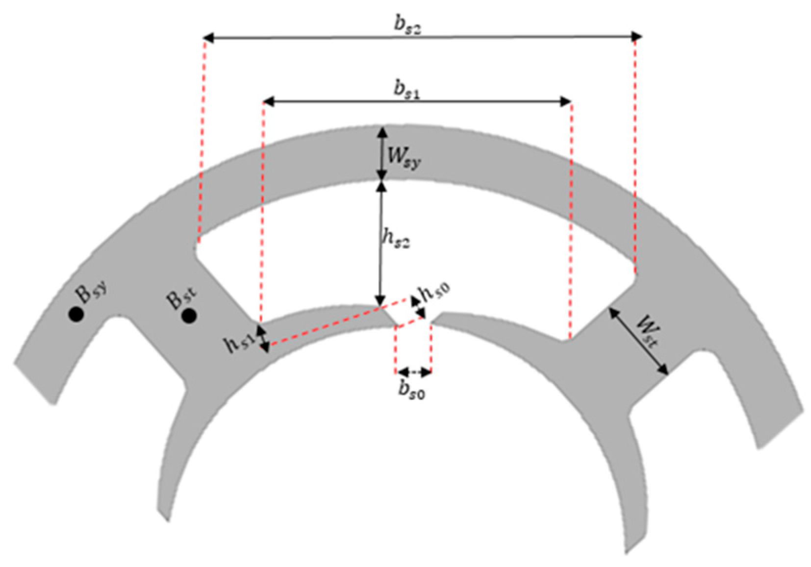
As part of the stator design process, dimensional calculations play a critical role, as they directly influence the performance of the magnetic circuit. In these calculations, various geometric parameters are determined based on the magnetic flux density, and the physical dimensions of the stator are defined accordingly. The stator geometry dimensions shown in Figure 7 are used as a reference for the calculations. To focus specifically on the electromagnetic performance of the proposed topology, the model presented in Figure 8 is generated without considering the coil winding process. In practical applications, such stator geometries can be wound either manually or by using an automated segmentation-based winding approach. The appropriate stator dimensions are calculated using Equations (30)–(34). In addition, Equations (32) and (33) are solved simultaneously during the calculation process. The resulting motor dimensions obtained from these calculations are presented in Table 1.
Figure 8 shows the model of the single-phase BLDC motor created in the ANSYS Maxwell 2D interface. In this design, a conical-shaped asymmetric air gap has been implemented, with a minimum of 0.5 mm and a maximum of 1 mm between the magnet and the air gap.
This air gap configuration effectively eliminates the dead point problem. To reduce cost, ferrite magnets were used in the rotor, which was designed with surface-mounted magnets.
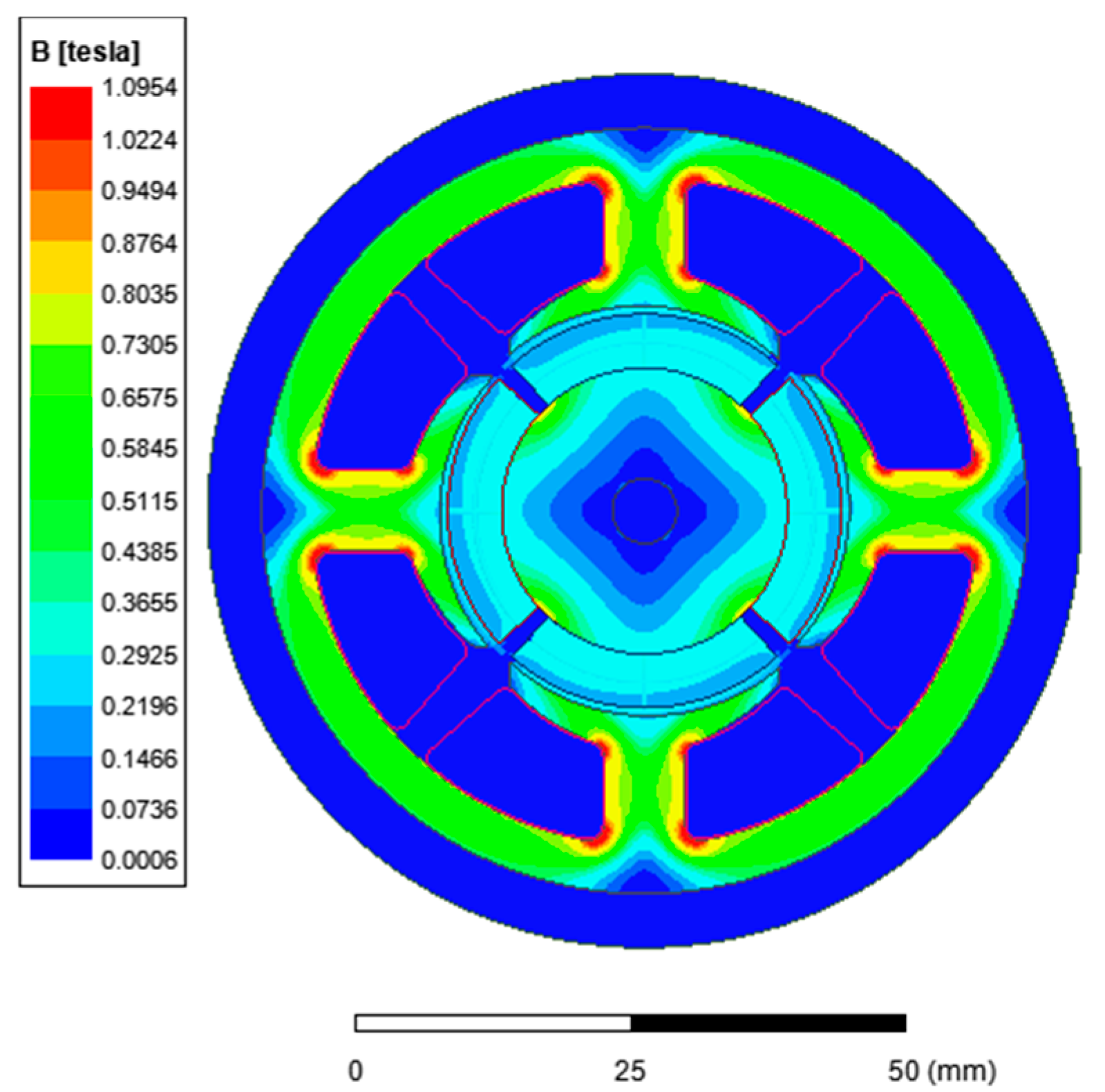
Figure 9 shows the magnetic flux density distribution of the motor. The analysis revealed that magnetic saturation did not occur in the sheet material and that the flux density values in the tooth and yoke regions shown in the figure remained within reasonable limits.
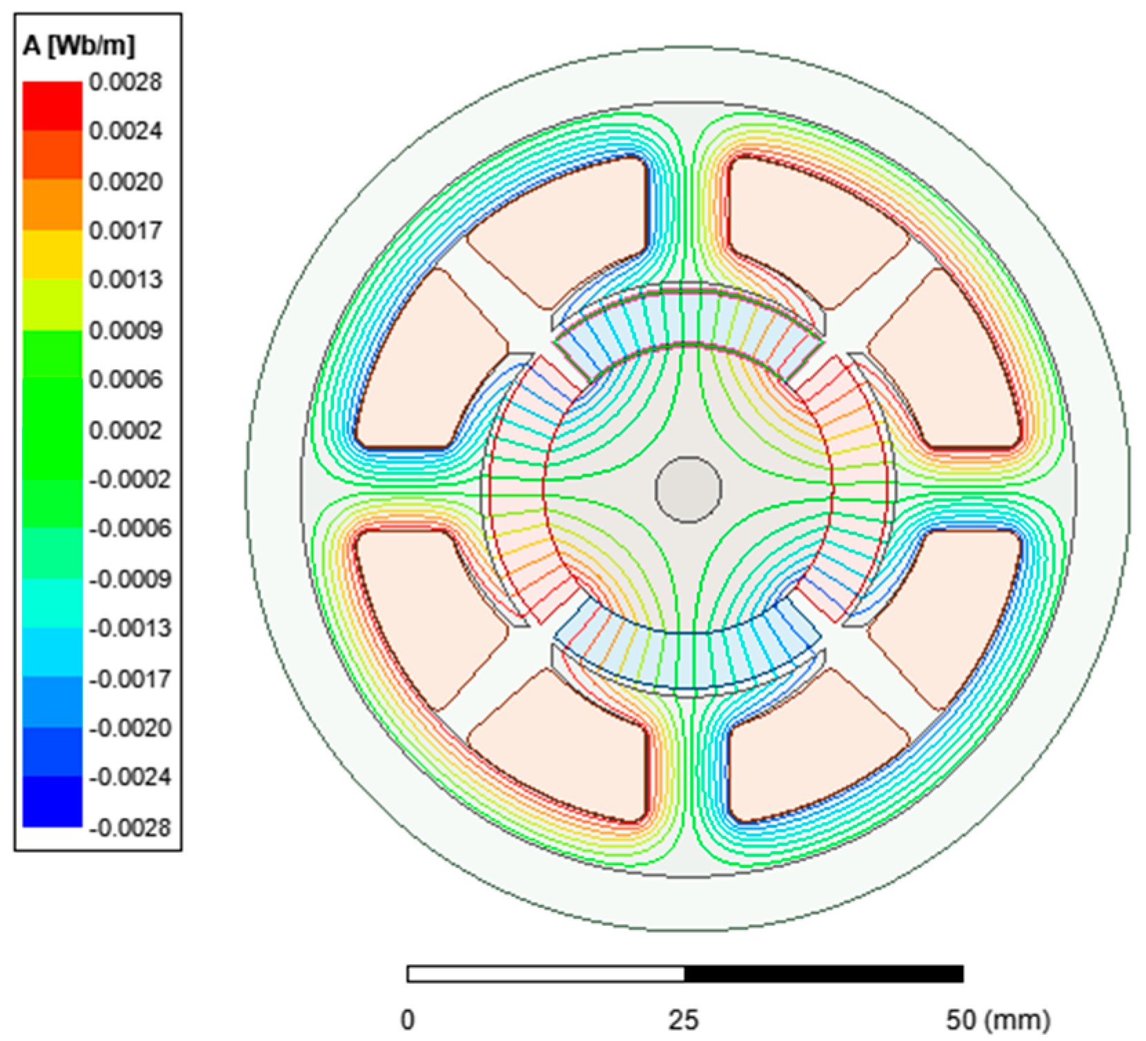
Figure 10 shows the distribution of magnetic flux. It can be observed that the flux lines have a uniform distribution and that no saturation occurs.
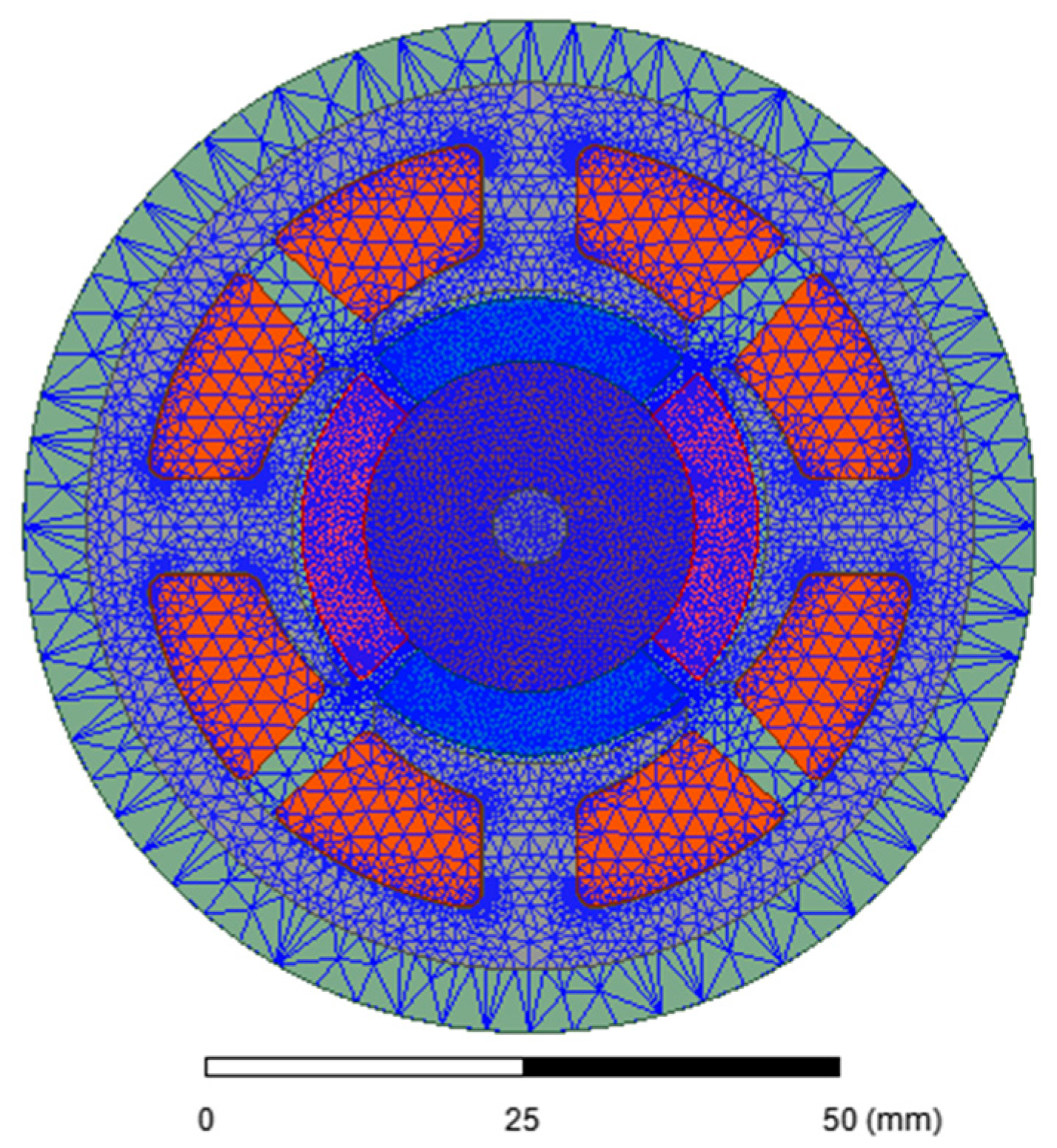
Figure 11 shows the analysis of the designed motor using the finite element method. In analyses performed using the finite element approach, both the number and size of the mesh elements play an important role in determining the accuracy of the results. Figure shows the mesh distribution of the single-phase BLDC motor model used in this study. In regions where flux density changes are critical, a finer mesh containing a greater number of elements is applied. Conversely, areas less sensitive to flux density are modeled with larger mesh elements. This approach increases the accuracy of the simulation while reducing the total computation time.
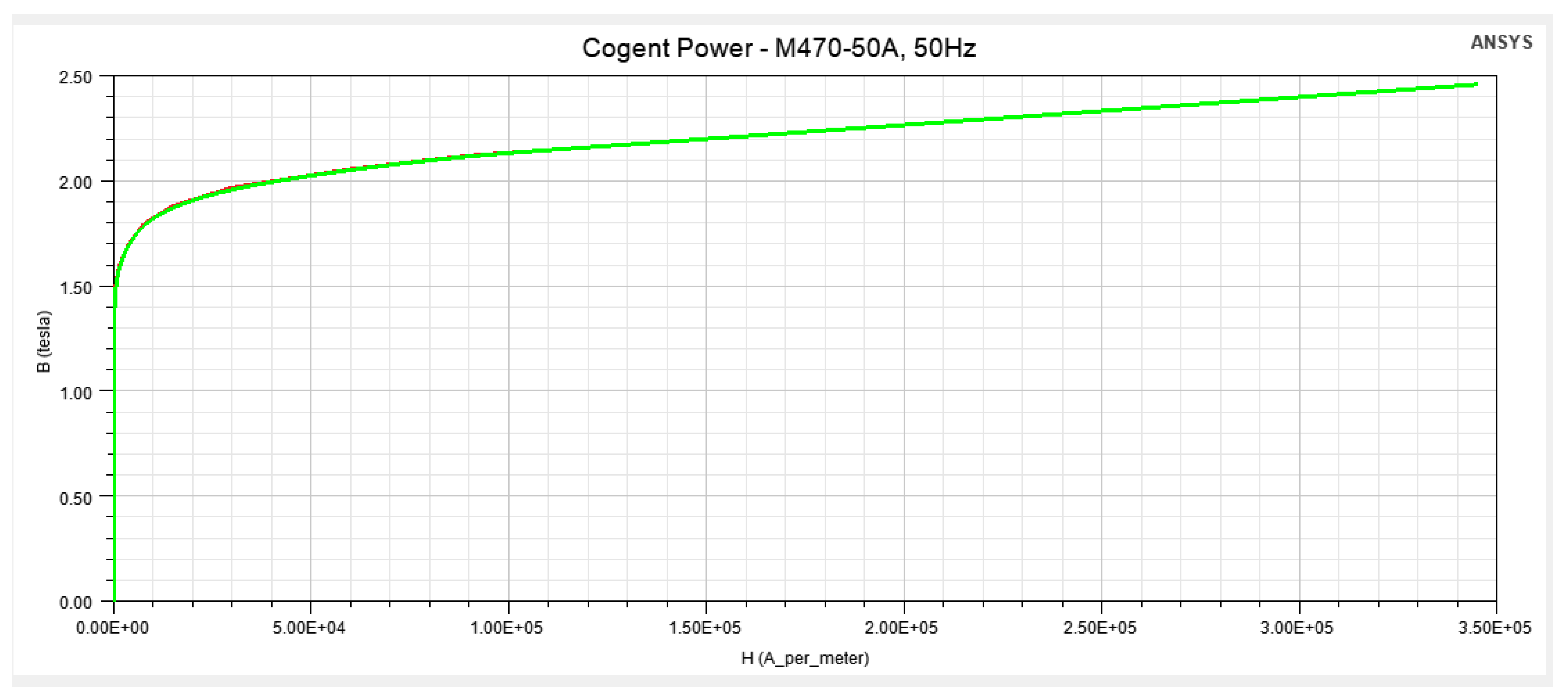
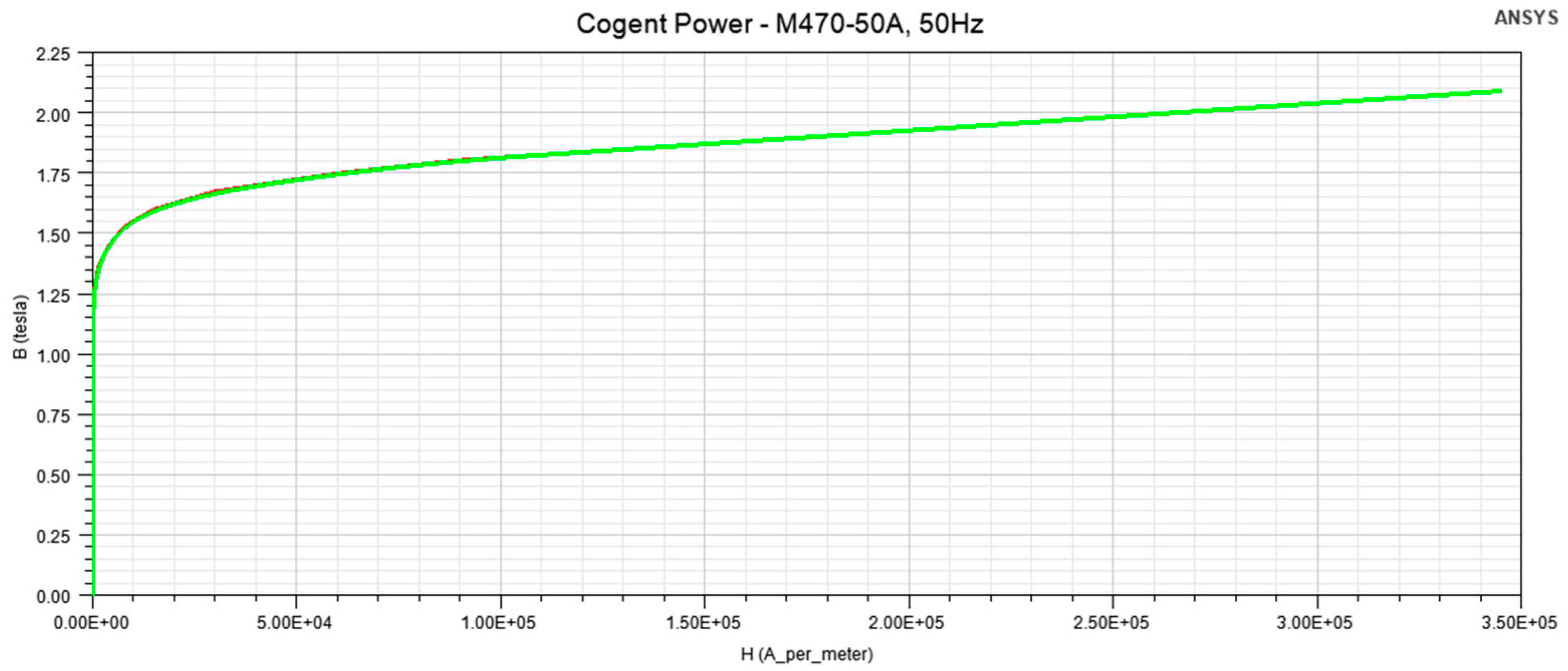
Ferromagnetic laminated steel was used. The employed lamination material is M470-50A, defined for 50 Hz. The M470 lamination material property in ANSYS Maxwell was modified by replacing the original BH curve with a “weakened” BH curve. For this purpose, the magnetic flux density (B) values were reduced by 15%. This reduction represents an empirical approach to model the decrease in effective permeability/flux density after the cutting process. In the literature, similar scaling factors have been used to represent cutting effects, and it has been reported that modifications on the B side have a more dominant impact on the model [35]. In addition, the stacking factor in the lamination material properties was set to 0.95. The stacking direction was defined as V [3].
Figure 12 shows the original B–H curve for the M470-50A, 50 Hz electrical sheet metal found in the ANSYS Maxwell library. This curve represents the nonlinear relationship between the magnetic flux density (B) and the magnetic field strength (H) of the material, clearly illustrating its behavior, particularly in the saturation region. In electric motor designs, the BH characteristic of the sheet material has a direct effect on the air gap flux density, magnetic saturation, iron losses, and indirectly on electromagnetic torque production.
Figure 13 shows the BH curve of the M470-50A electrical steel sheet with magnetic flux density weakened by 15%. This weakening process was applied to represent the magnetic insulation layers formed during sheet packaging, stresses caused by mechanical cutting, and post-manufacturing magnetic property losses. This approach is a modeling technique commonly used in the literature that provides results closer to reality in finite element analysis (FEA). With the weakening of the BH curve, the flux density obtained under the same magnetic field strength decreases; this directly affects the air gap flux density, torque production, and iron losses.


2.3. Optimization of Asymmetric Air Gap Geometry

The introduction of an asymmetric air gap is a deliberate design choice to enable self-starting capability in single-phase BLDC motors. However, the initial design, utilizing a standard air gap ratio of 2:1 ( g m a x = 1.0   mm ,   g m i n = 0.5   mm ) resulted in sharp variations in magnetic reluctance. As highlighted in the preliminary simulation results, this configuration effectively eliminated dead points but introduced excessive cogging torque, leading to high torque ripple. To address this trade-off and substantiate the motor’s performance, a parametric optimization study was conducted using ANSYS Maxwell 2D.
The primary objective of the optimization process was to minimize the torque ripple ratio ( T r i p p l e ) while strictly maintaining the starting torque ( T s t a r t ) above a critical threshold to ensure reliable startup. The torque ripple ratio is defined as:
T r i p p l e = T m a x T m i n T a v g 100  
Two key geometric parameters were selected as design variables for the optimization sweep:
  • Air Gap Ratio (kg): Defined as the ratio between the maximum and minimum air gap lengths (gmax/gmin). The parametric sweep was conducted for kg values ranging from 1.5 to 2.5
  • Tapering Angle ( θ taper ): This parameter defines the slope of the stator pole shoe. It directly influences the smoothness of the reluctance transition. The angle was varied to modify the flux interaction profile.
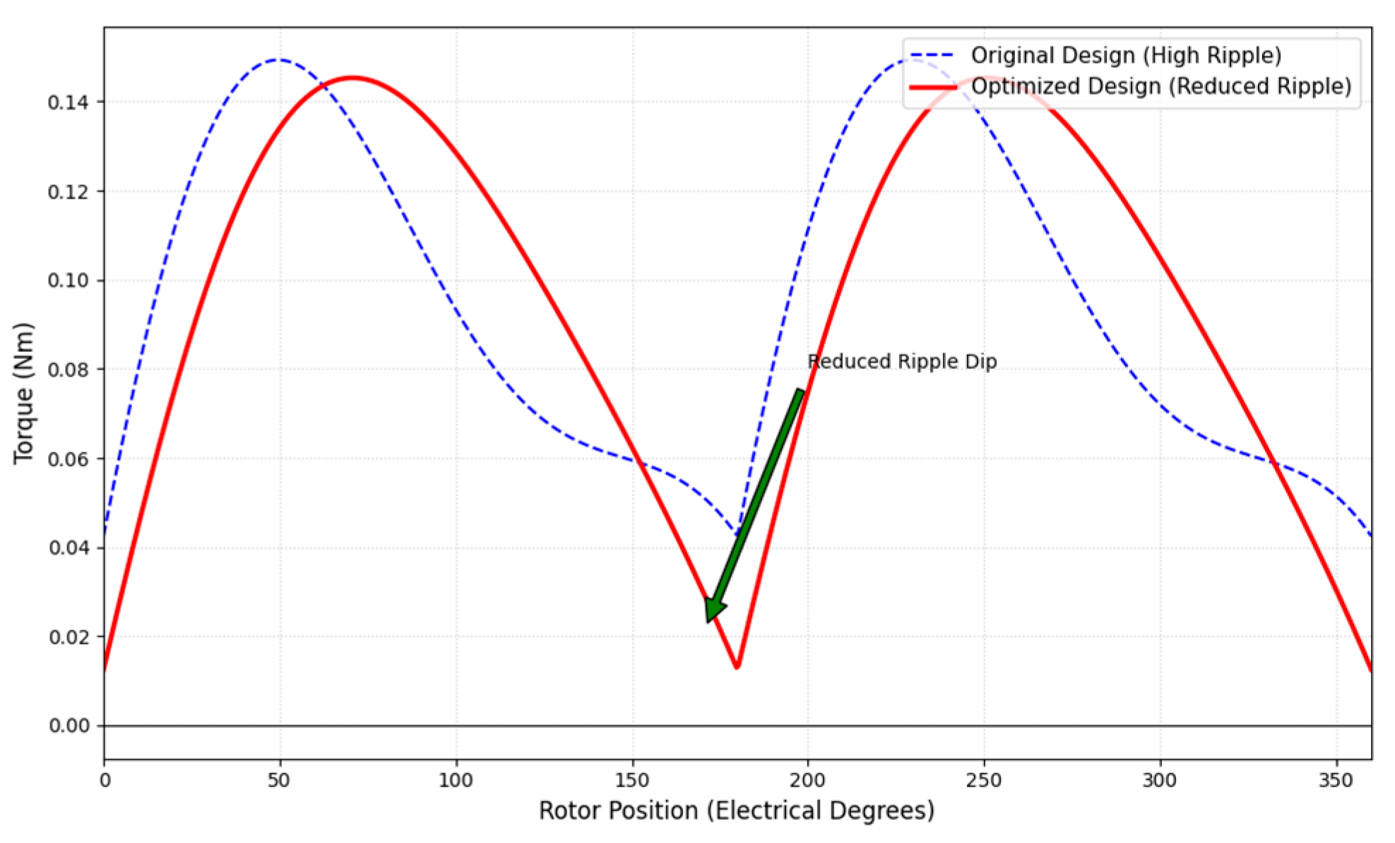
The parametric analysis revealed that the initial ratio of 2:1 ( k g = 2.0) generated excessive reluctance torque components that amplified the total torque ripple. By iteratively adjusting the design variables, the optimal configuration was identified at an air gap ratio of approximately 1.7:1. This optimized geometry provides a smoother transition for the magnetic flux lines, significantly reducing the “dip” in the total torque waveform without compromising the detent torque required for parking the rotor in a favorable position. As a result of this optimization procedure:
  • The average torque was maintained at the target level of approximately 0.12 Nm.
  • The torque ripple was reduced by approximately 18% compared to the initial design.
  • The self-starting capability was preserved, with the minimum instantaneous torque remaining positive throughout the commutation zone.
Figure 14 illustrates the comparison between the initial and optimized torque waveforms, demonstrating the reduction in ripple amplitude and the elimination of deep negative torque spikes.
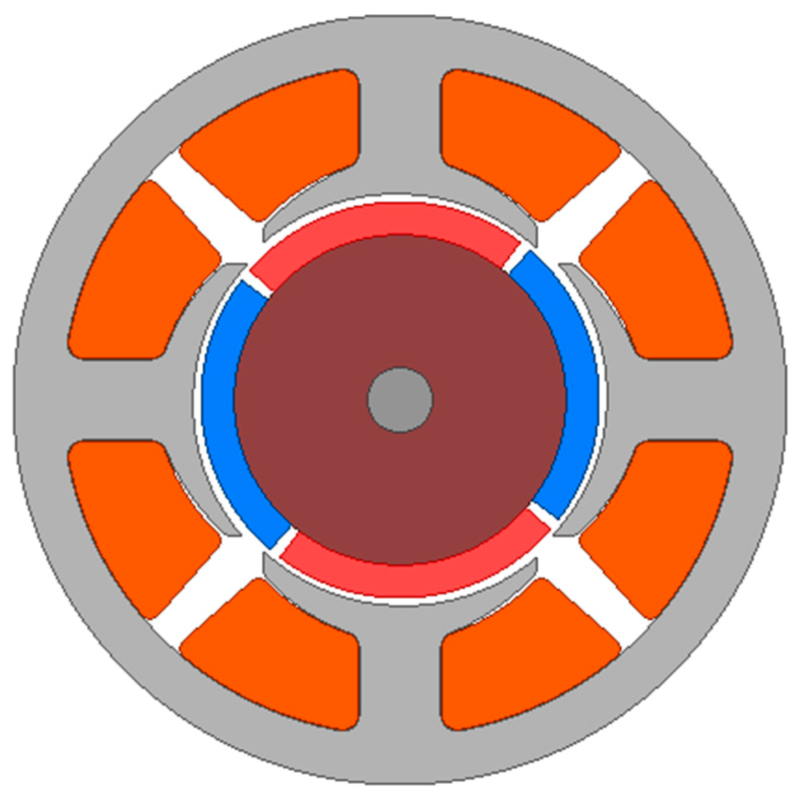
Figure 14 presents the comparison of the total torque waveforms between the initial design (2:1 ratio) and the optimized design (1.7:1 ratio). The optimized design (red solid line) exhibits reduced ripple and a smoother profile compared to the initial design (blue dashed line) while maintaining positive starting torque. As observed, the optimization of the asymmetric air gap geometry has smoothed the torque profile. The peak-to-peak torque ripple has been reduced by approximately 18%. Crucially, the optimized design maintains a positive minimum torque, confirming that the ‘dead points’ are mitigated with a more stable output compared to the initial design.

3. Simulation Results

In the analysis results, the output parameters of the single-phase BLDC motor used in combi fan applications have been examined.
Table 2 presents a comparison between the analytically calculated parameters and the corresponding results obtained from finite element method (FEM) simulations for the proposed single-phase BLDC motor. As observed from the table, the analytical and FEM results exhibit a high level of agreement in terms of average torque, operating speed, air-gap flux density, and back-EMF. The small discrepancies between the two approaches can be attributed to simplifying assumptions adopted in the analytical model, such as uniform magnetic flux distribution and neglected local saturation effects, whereas the FEM analysis accounts for detailed electromagnetic field distributions and material nonlinearities. Overall, the close correspondence between the analytical predictions and FEM results confirms the validity and reliability of the proposed analytical design methodology.
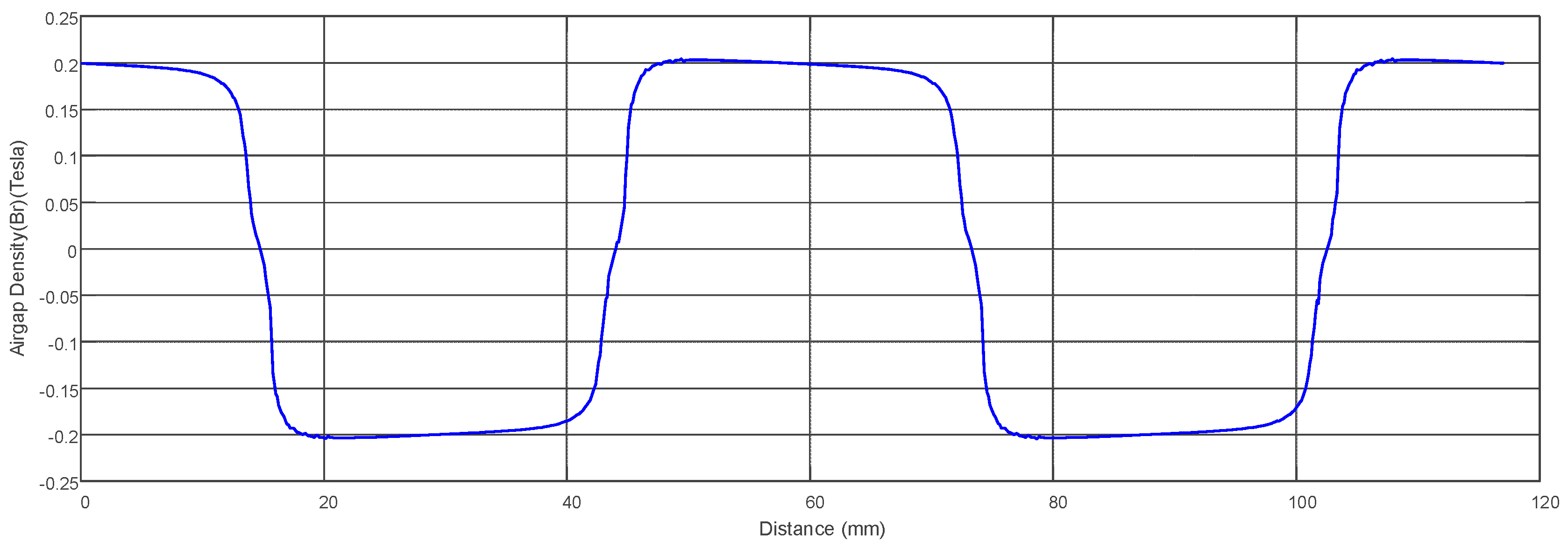
In the ANSYS analysis, the air gap flux density of the single-phase BLDC motor was obtained as shown in Figure 15. As seen in the figure, the flux density in the air gap is relatively low due to the use of ferrite magnets in the rotor. The average absolute flux density in the air gap was calculated to be approximately 0.18 Tesla. The variation in the slope of the flux density in both positive and negative values is attributed to the stepped inclination of the stator pole shoe, which was implemented to create the asymmetric air gap.
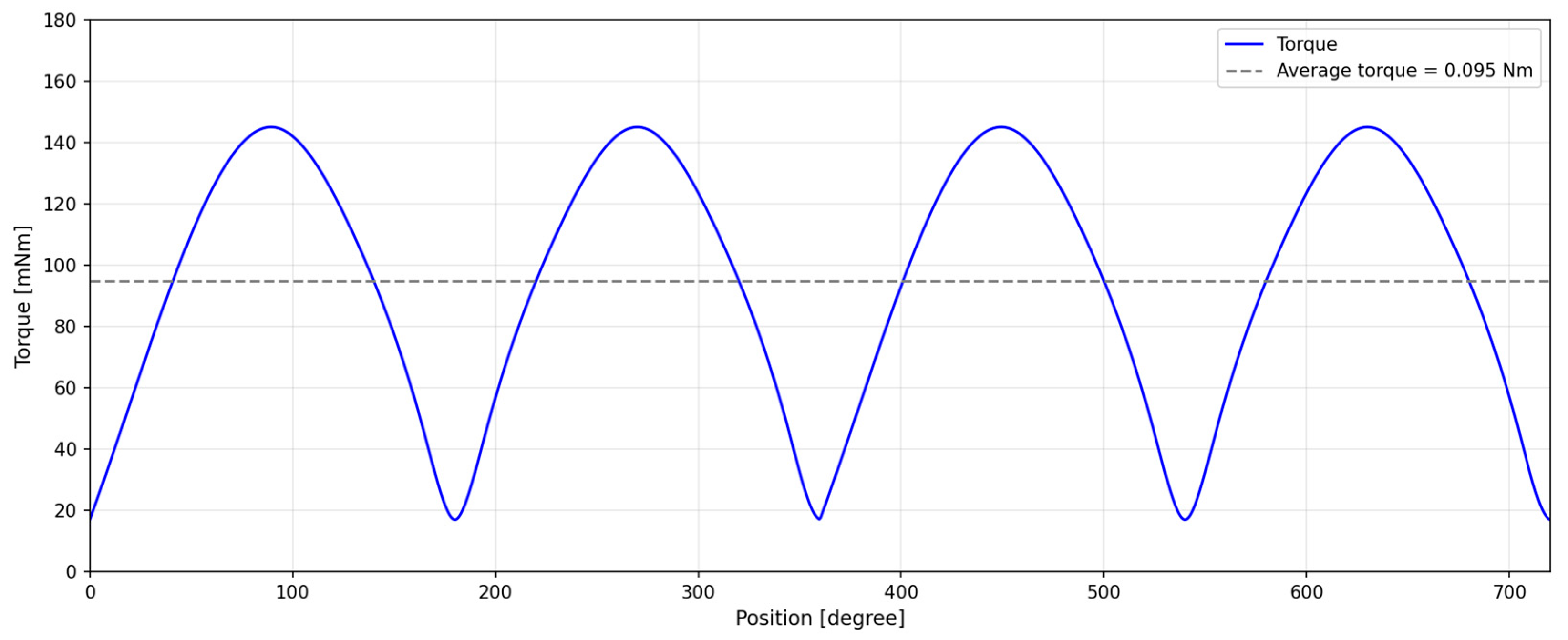
Figure 16 illustrates the variation of the motor total torque with respect to rotor position. According to the ANSYS analysis, the average torque of the motor was found to be approximately 0.095 Nm, which aligns well with the target torque specified at the beginning of the design process.
Torque ripple is evident in the torque–position curve, primarily due to the applied switching strategy. These ripples, a structural drawback of single-phase BLDC motors, can cause vibrations and acoustic noise during operation. Nevertheless, the implementation of the asymmetric air gap design, along with consideration of advance and dwell angles during the driving process, has effectively eliminated dead points at specific rotor positions. The most compelling evidence of this improvement is that torque remains consistently in the positive region throughout the entire 0–720° rotation, without falling into negative values, indicating stable and efficient torque generation across all rotor positions.
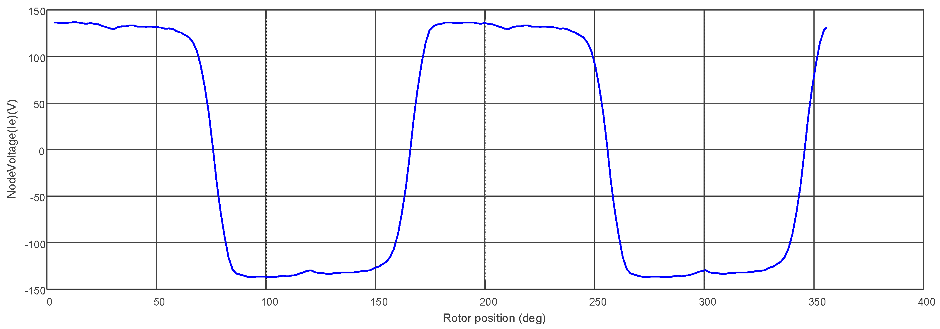
Figure 17 shows the variation of the back electromotive force (Back-EMF) of the single-phase BLDC motor as a function of rotor position. Back-EMF refers to the voltage induced in the stator windings during the rotation of the motor’s rotor. This voltage is directly related to the motor’s speed and magnetic flux. The waveform in the graph reveals that the Back-EMF takes the form of a square wave. This results from the triangular waveform of the motor’s magnetic flux linkage. According to Faraday’s law, the derivative of the flux linkage yields the Back-EMF, and the derivative of a triangular waveform produces a square wave.
The periodic variation of the Back-EMF indicates that the motor is rotating properly and that the magnetic field is varying consistently. Additionally, the Back-EMF variation shows a strong resemblance to the air gap flux density variation, confirming that the Back-EMF is directly related to the magnetic flux density. The asymmetric air gap design has introduced slopes in both the positive and negative directions of the flux density, which has also created a similar effect in the Back-EMF waveform.
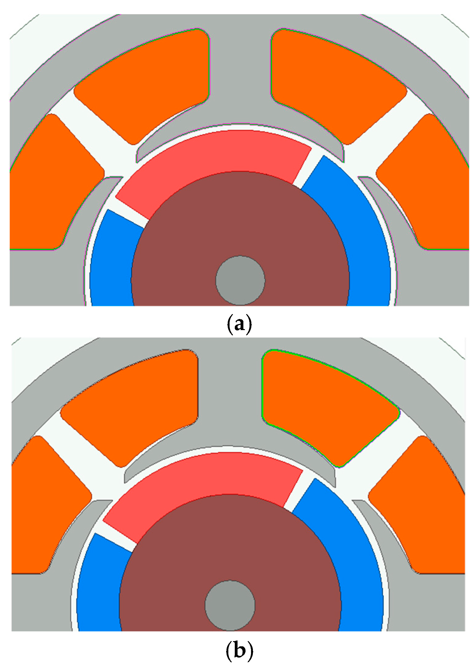
Figure 18 presents the comparative cross-sectional geometries of the reference and proposed motor topologies. (a) Symmetric reference model: as seen in Figure 18a, the reference motor features a uniform air gap between the stator pole shoes and the rotor magnets. While this symmetry provides a balanced magnetic circuit, the resulting equilibrium positions coincide with the magnetic dead points, leading to startup failures. (b) Proposed asymmetric model: the proposed design in Figure 18b incorporates a tapered air gap geometry. This structural modification introduces a variation in magnetic reluctance (cogging) that deliberately shifts the rotor’s resting position (detent position) away from the null-torque region, thereby mechanically enabling self-starting capabilities.
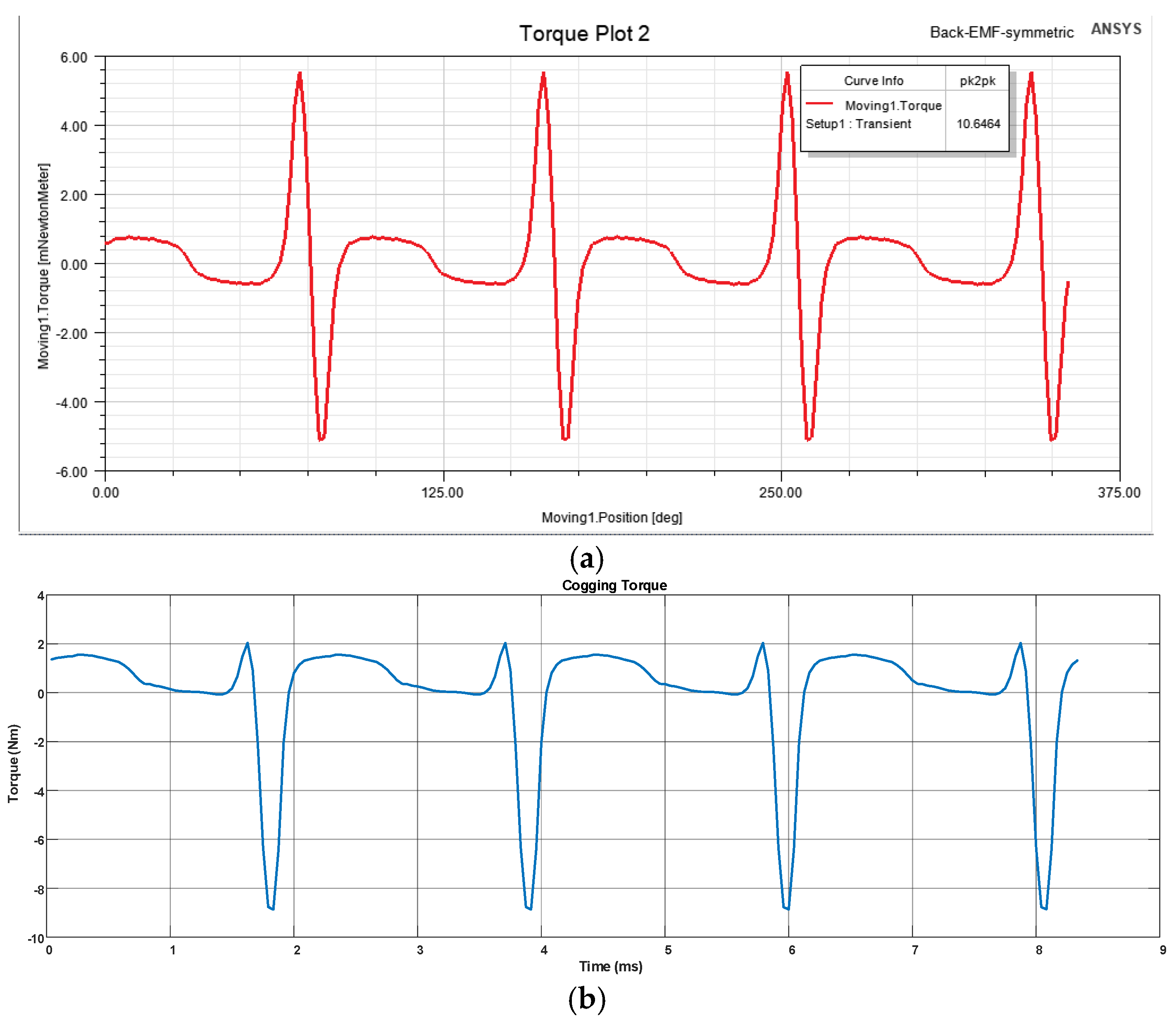
Figure 19 compares the cogging torque waveforms of the symmetric and asymmetric designs obtained under identical simulation conditions. Waveform analysis: The symmetric model (Figure 19a) exhibits a highly balanced waveform with a peak-to-peak value of 10.65 mNm. However, its zero-crossing alignment confirms the inability to self-start. In contrast, the asymmetric design (Figure 19b) displays a shifted and unbalanced profile, where negative peak values (approx. −8.5 mNm) become more dominant compared to positive peaks. Quantitative impact: The analysis reveals that the asymmetry results in a marginal increase in peak-to-peak cogging torque, rising from 10.65 mNm to 10.91 mNm (an increase of approximately 2.5%). Despite this slight increase in torque ripple, the asymmetric geometry successfully creates a stable parking zone, validating the trade-off between a minor increase in cogging torque and the achievement of reliable self-starting.
As detailed in Table 3, the transition to an asymmetric topology fundamentally alters the motor’s behavior. While the symmetric design offers superior NVH (Noise, Vibration, and Harshness) performance due to its balanced waveform, it lacks the necessary starting torque. Conversely, the asymmetric design accepts a marginal increase in cogging torque and vibration as a necessary trade-off to guarantee reliable self-starting capability.
Cogging torque arises from the magnetic attraction between the rotor magnets and the stator pole shoes, and it can negatively affect the smooth operation of the motor, causing vibrations, acoustic noise, and irregularities in low-speed performance. According to the analysis results, distinct peak points are observed in the graph. These peaks are associated with sudden changes in magnetic reluctance at specific rotor positions. More specifically, they correspond to positions where the rotor magnets align with the stator teeth. At each alignment point, the magnetic attraction force increases, resulting in a sudden rise (peak) in cogging torque. While the proposed asymmetric air gap design successfully eliminates the dead point issue, it also leads to an increase in cogging torque.
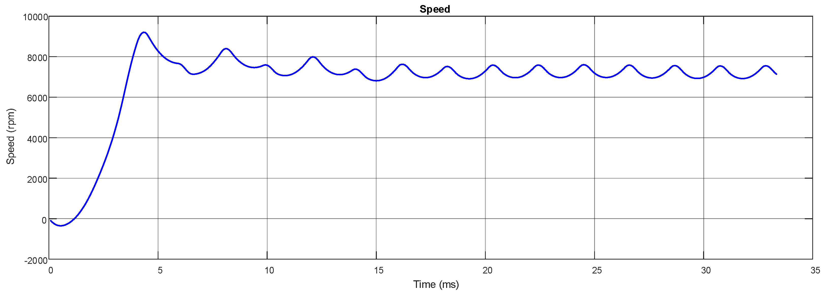
Figure 20 illustrates the time-dependent variation of the motor’s speed. Speed is a critical parameter in evaluating motor performance, and it is directly related to torque, cogging torque, and the motor’s electromagnetic design. The graph shows noticeable fluctuations in the speed values, which are associated with torque ripple and cogging torque. Cogging torque results from the magnetic attraction between the rotor magnets and the stator teeth and can interfere with smooth motor operation. This effect is particularly detrimental at low speeds, where motor performance may be significantly impacted. Although the proposed asymmetric air gap design successfully eliminates the dead point issue, it does not fully suppress torque ripple. This limitation is reflected in the speed graph as fluctuations. However, the overall stability of the speed value indicates that the motor is capable of continuous operation and that the dead point problem has been effectively resolved. The graph also shows that the motor undergoes an initial acceleration phase before reaching and maintaining a steady operating speed. This confirms that the motor operates in accordance with the design objectives and is well-suited for applications such as combi fan systems.
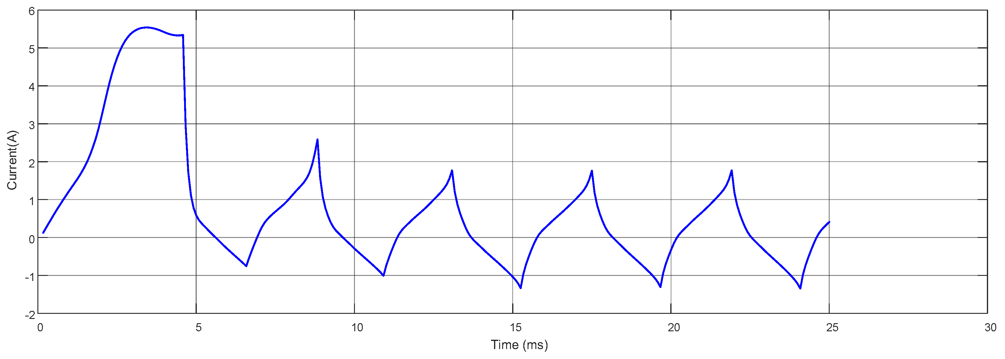
Figure 21 shows the time-dependent variation of the stator current. In the steady-state region, it is observed that the current waveform has a periodic structure and contains noticeable fluctuations. The waveform also indicates the presence of harmonic components. This is an expected outcome, particularly in single-phase BLDC motors, where the asymmetric air gap design introduces varying reluctance effects in the magnetic circuit, leading to current oscillations. As a result, the current graph demonstrates that the motor requires a high initial current during the startup phase and exhibits a certain level of current ripple during steady-state operation. Minimizing these fluctuations can enhance the overall efficiency of the motor and contribute to reducing power losses within the power electronics circuit.

4. Discussion

The results obtained in this study highlight the effectiveness of asymmetric air gap geometry in addressing one of the most critical limitations of single-phase BLDC motors—namely, the dead point phenomenon. The proposed conical air gap successfully provides a continuous positive torque profile, confirming that the rotor can initiate and maintain rotation without the need for any auxiliary starting mechanism. This improvement directly enhances the motor’s reliability and usability in applications such as combi fans, where compactness and simplicity are essential. The comparative analysis in Section 3 confirms that the transition to an asymmetric geometry results in a negligible increase in peak-to-peak cogging torque (from 10.65 mNm to 10.91 mNm). This 2.5% increase is an acceptable compromise, as it eliminates the critical ‘dead point’ failure mode observed in the symmetric reference model. The results demonstrate that the design successfully balances the requirement for reliable startup with the need to minimize vibration-inducing torque ripples. The periodic fluctuations observed in torque and speed profiles are mainly caused by the unbalanced magnetic pull generated by the asymmetric air gap and the single-phase excitation nature. These torque variations can lead to acoustic noise, vibration, and reduced efficiency, particularly under light-load conditions. To mitigate these effects, several strategies can be considered. First, optimization of the advance and dwell angles in the drive circuit can help smooth torque transitions during commutation. Additionally, introducing skewed stator slots, optimized pole shapes, or auxiliary notches can effectively reduce cogging torque without compromising the starting performance. Furthermore, adopting multi-objective optimization techniques—for example, by integrating finite element models with metaheuristic algorithms such as genetic algorithms or particle swarm optimization—can achieve an optimal balance between starting torque, torque ripple, and overall efficiency. The results also underline that the use of ferrite magnets, while cost-effective, inherently limits the magnetic flux density in the air gap. Replacing ferrite magnets with rare-earth materials such as NdFeB could significantly enhance torque density, albeit with an increase in material cost. A comparison was made between the proposed single-phase BLDC motor and the axial-flux single-phase BLDC motor analyzed by Mendrela & Jagieła (2004) [36]. The motors designed for low-speed water pump applications produce significantly higher torque (3.2–3.4 Nm at 5.25 A) and achieve efficiency in the range of 75–85% depending on the commutation angle. In contrast, the proposed conical air gap motor operates at a much higher speed (7014 rpm) with an average torque of only 0.119 Nm at 0.79 A. Torque and efficiency are lower due to the low-power fan-type application and the use of ferrite magnets [36]. Future studies should therefore explore trade-off analyses between performance gains and cost implications. Although the single-phase topology inherently exhibits higher torque ripple compared to three-phase counterparts due to the zero-crossing of the back-EMF, the optimization study presented in Section 2.3 has effectively minimized this effect. The remaining ripple is an acceptable design trade-off required to secure the self-starting capability without auxiliary windings or Hall sensors. The consistency of the simulation results after optimization confirms the validity of the proposed asymmetric design for fan-type applications.
Finally, the combination of analytical and FEA-based design validation used in this work proves to be a robust framework for single-phase BLDC motor design. Experimental verification of the simulated results will be essential to confirm the practical applicability of the proposed asymmetric air gap design. Moreover, extending this approach to multi-phase or hybrid excitation topologies could further improve dynamic response and energy efficiency in next-generation low-power drives.

5. Conclusions

In this study, the design of a single-phase BLDC motor used in combi fan applications was addressed, and an asymmetric air gap design was proposed to eliminate the dead point issue. The performance of the proposed design was evaluated through analytical calculations and finite element analysis (FEA) conducted using ANSYS Maxwell 2D. According to the analysis results, the implementation of an asymmetric air gap successfully eliminated dead points occurring at specific rotor positions and ensured continuous motor operation. However, it was also observed that this design led to torque ripple. The optimal air gap ratio was determined to be approximately 2:1, and the flux density in the air gap was calculated to be around 0.18 Tesla. The torque analysis revealed that the average torque of the motor is approximately 0.095 Nm, although torque ripple—an inherent drawback of single-phase BLDC motors—could not be completely eliminated.
This study provides a comprehensive analysis of how air gap design affects the performance of single-phase BLDC motors, thereby contributing to the existing literature. It demonstrates that the dead point problem can be addressed through air gap optimization, offering a practical alternative to improve motor reliability without the need for an additional starting mechanism. The findings of this work may serve as a foundation for future optimization studies aimed at enhancing the performance of single-phase BLDC motors.
In conclusion, this study shows that air gap optimization is an effective method for resolving the dead point issue in single-phase BLDC motors. However, further research is needed to minimize torque ripple and enhance overall motor efficiency. Future studies will play a significant role in improving the performance of such motors in commercial applications and expanding their industrial adoption.

Author Contributions

Conceptualization, A.O. and S.Y.; methodology, A.O.; software, S.Y.; validation, A.O. and S.Y.; formal analysis, A.O.; investigation, A.O.; resources, S.Y.; data curation, S.Y.; writing—original draft preparation, A.O.; writing—review and editing, S.Y.; visualization, S.Y.; supervision, A.O.; project administration, A.O. All authors have read and agreed to the published version of the manuscript.

Funding

This research received no external funding.

Data Availability Statement

The raw data supporting the conclusions of this article will be made available by the authors on request.

Conflicts of Interest

The authors declare no conflicts of interest.

References

  1. Lee, Y.-S.; Jo, N.-R.; Pyo, H.-J.; Jung, D.-H.; Kim, W.-H. Study on Single-Phase BLDC Motor Design through Drive IC Integration Analysis. Machines 2023, 11, 1003. [Google Scholar] [CrossRef] [Scilit]
  2. Kimr, H.C.; Han, J.H.; Jung, T.U. Analysis of Torque Characteristic According to the Asymmetrical Airgap of the BLDC Motor for Cooling-Fan. In Proceedings of the 2013 International Conference on Electrical Machines and Systems (ICEMS), Busan, Republic of Korea, 26–29 October 2013; Volume 2013, pp. 1277–1280. [Google Scholar] [CrossRef] [Scilit]
  3. Lefley, P.; Ahmed, S. Development of a Single Phase PM BLDC Motor from a Novel Generic Model. In Proceedings of the 2009 11th Spanish Portuguese Conference on Electrical Engineering—11CHLIE, Zaragoza, Spain, 2–4 July 2009. [Google Scholar]
  4. Chiu, C.L.; Chen, Y.T.; Shen, Y.H.; Liang, R.H. An Accurate Automatic Phase Advance Adjustment of Brushless DC Motor. IEEE Trans. Magn. 2009, 45, 120–126. [Google Scholar] [CrossRef] [Scilit]
  5. Fazil, M.; Rajagopal, K.R. A Novel Air-Gap Profile of Single-Phase Permanent-Magnet Brushless DC Motor for Starting Torque Improvement and Cogging Torque Reduction. IEEE Trans. Magn. 2010, 46, 3928–3932. [Google Scholar] [CrossRef] [Scilit]
  6. Zhang, Y.; Gono, R.; Jasinski, M. An Improvement in Dynamic Behavior of Single Phase PM Brushless DC Motor Using Deep Neural Network and Mixture of Experts. IEEE Access 2023, 11, 64260–64271. [Google Scholar] [CrossRef] [Scilit]
  7. Bentouati, S.; Zhu, Z.Q.; Howe, D. Influence of Design Parameters on the Starting Torque of a Single-Phase PM Brushless DC Motor. IEEE Trans. Magn. 2000, 36, 3533–3536. [Google Scholar] [CrossRef] [Scilit]
  8. Hwang, H.; Cho, J.; Hwang, S.-H.; Choi, J.Y.; Lee, C. Design of a Single-Phase BLDC Motor for a Cordless Vacuum Cleaner Considering the Efficiency of Airflow. Energies 2019, 12, 465. [Google Scholar] [CrossRef] [Scilit]
  9. Mayer, J.S.; Wasynczuk, O. Analysis and Modeling of a Single-Phase Brushless DC Motor Drive System. IEEE Trans. Energy Convers. 1989, 4, 473–479. [Google Scholar] [CrossRef] [PubMed]
  10. Liu, Y.; Wang, Y.; Pang, L.; Guo, Y.; Qin, D.; Guan, Q. Electromagnetic Noise Analysis in Single-Phase Brushless Motors Based on Multiphysics Coupling. In Proceedings of the 2025 IEEE 2nd International Conference on Energy and Electrical Engineering (EEE), Nanchang, China, 20–21 June 2025; IEEE: Piscataway, NJ, USA, 2025; pp. 1–5. [Google Scholar]
  11. Hong, D.K.; Woo, B.C.; Koo, D.H.; Seo, U.J. A Single-Phase Brushless DC Motor with Improved High Efficiency for Water Cooling Pump Systems. IEEE Trans. Magn. 2011, 47, 4250–4253. [Google Scholar] [CrossRef] [Scilit]
  12. Kwon, B.-I.; Yang, B.-Y.; Park, S.-C.; Jin, Y.-S. Novel Topology of Unequal Air Gap in a Single-Phase Brushless DC Motor. IEEE Trans. Magn. 2001, 37, 3723–3726. [Google Scholar] [CrossRef]
  13. Lizhi, S.; Qi, F.; Jing, S. Drive of Single-Phase Brushless DC Motors Based on Torque Analysis. IEEE Trans. Magn. 2007, 43, 46–50. [Google Scholar] [CrossRef] [Scilit]
  14. Hamlet, A.; Hribernik, B. Impact of Shape of Stator Pole of One Phase Brushless Motor on Cogging Torque. IEEE Trans. Magn. 1996, 32, 1545–1548. [Google Scholar] [CrossRef] [Scilit]
  15. Jurkovic, S.; Rahman, K.M.; Savagian, P.J. Design, Optimization and Development of Electric Machine for Traction Application in GM Battery Electric Vehicle. In Proceedings of the 2015 IEEE International Electric Machines & Drives Conference (IEMDC), Coeur d’Alene, ID, USA, 10–13 May 2015; IEEE: Piscataway, NJ, USA, 2015; pp. 1814–1819. [Google Scholar]
  16. Rostami, N. High Efficiency Axial Flux Permanent Magnet Machine Design for Electric Vehicles. Gazi Univ. J. Sci. 2019, 32, 544–556. [Google Scholar]
  17. Liu, C.; Zhu, J.; Wang, Y.; Lei, G.; Guo, Y.; Liu, X. Design and Analysis of an Outer Rotor Flux Switching Permanent Magnet Machine for Electric Vehicle. In Proceedings of the 2015 IEEE Magnetics Conference (INTERMAG), Beijing, China, 11–15 May 2015; IEEE: Piscataway, NJ, USA, 2015; p. 1. [Google Scholar]
  18. Jiménez, M.; Tapia, J.; Lindh, P.; Aarniovuori, L.; Anttila, A.; Pyrhönen, J. Alternative Procedures for Thermal Design on Electric Machine. In Proceedings of the 2021 IEEE International Electric Machines & Drives Conference (IEMDC), Hartford, CT, USA, 17–20 May 2021; IEEE: Piscataway, NJ, USA, 2021; pp. 1–6. [Google Scholar]
  19. Dong, Z.; Yan, L.; Su, H. Modal Analysis of An External Rotor Machine For Electric Propulsion Aircraft. In Proceedings of the 2022 IEEE 17th Conference on Industrial Electronics and Applications (ICIEA), Chengdu, China, 16–19 December 2022; IEEE: Piscataway, NJ, USA, 2022; pp. 1658–1662. [Google Scholar]
  20. Golovanov, D.; Gerada, D.; Papini, L.; Xu, Z.; Gerada, C. A Holistic Electrical Machine Design Tool for More-Electric and Hybrid-Electric Aircraft. In Proceedings of the 2018 IEEE International Conference on Electrical Systems for Aircraft, Railway, Ship Propulsion and Road Vehicles & International Transportation Electrification Conference (ESARS-ITEC), Nottingham, UK, 7–9 November 2018; IEEE: Piscataway, NJ, USA, 2018; pp. 1–6. [Google Scholar]
  21. Radmanesh, H.; Sharifi, R. Design and Simulation of Axial Flux Permanent Magnet Electrical Machine for Electric Vehicles Application. In Proceedings of the 2021 29th Iranian Conference on Electrical Engineering (ICEE), Tehran, Iran, 18–20 May 2021; IEEE: Piscataway, NJ, USA, 2021; pp. 340–345. [Google Scholar]
  22. Khoshoo, B.; Blank, J.; Pham, T.; Deb, K.; Foster, S. Optimized Electric Machine Design Solutions with Efficient Handling of Constraints. In Proceedings of the 2021 IEEE Symposium Series on Computational Intelligence (SSCI), Orlando, FL, USA, 5–7 December 2021; IEEE: Piscataway, NJ, USA, 2021; pp. 1–8. [Google Scholar]
  23. Stamenkovic, I.; Schofield, N.; Milivojevic, N.; Krishnamurthy, M.; Emadi, A. A Novel Modular Permanent-Magnet Electric Machine Design. In Proceedings of the 2009 35th Annual Conference of IEEE Industrial Electronics, Porto, Portugal, 3–5 November 2009; IEEE: Piscataway, NJ, USA, 2009; pp. 997–1002. [Google Scholar]
  24. Du-Bar, C.; Thiringer, T.; Lundmark, S.; Alatalo, M. An Electric Machine Design Procedure That Includes Multiple Cost Scenarios. In Proceedings of the 2016 18th European Conference on Power Electronics and Applications (EPE’16 ECCE Europe), Karlsruhe, Germany, 5–9 September 2016; IEEE: Piscataway, NJ, USA, 2016; pp. 1–9. [Google Scholar]
  25. Kamberov, K.; Ivanov, A.; Zlatev, B. A Novelty Design of an Axial Flux Induction Electrical Machine with Low Manufacturing Cost. In Proceedings of the 2021 13th Electrical Engineering Faculty Conference (BulEF), Varna, Bulgaria, 8–11 September 2021; IEEE: Piscataway, NJ, USA, 2021; pp. 1–5. [Google Scholar]
  26. Bramerdorfer, G. Tolerance Analysis for Electric Machine Design Optimization: Classification, Modeling and Evaluation, and Example. IEEE Trans. Magn. 2019, 55, 8106809. [Google Scholar] [CrossRef] [Scilit]
  27. Züst, S.; Züst, R.; Schudeleit, T.; Wegener, K. Development and Application of an Eco-Design Tool for Machine Tools. Procedia CIRP 2016, 48, 431–436. [Google Scholar] [CrossRef] [Scilit]
  28. Chen, Y.T.; Chiu, C.L.; Jhang, Y.R.; Tang, Z.H.; Liang, R.H. A Driver for the Single-Phase Brushless DC Fan Motor with Hybrid Winding Structure. IEEE Trans. Ind. Electron. 2013, 60, 4369–4375. [Google Scholar] [CrossRef] [Scilit]
  29. Gomez, M.; Pallones, M. Single-Phase BLDC Motor Driver; AN2049; Microchip Technology: Chandler, AZ, USA, 2016. [Google Scholar]
  30. Tan, J.E.; Quismundo, J.P.; Tarvina, M.A. Single-Phase BLDC Motors for External Fan Applications. In Proceedings of the PCIM Conference 2025, Nürnberg, Germany, 6–8 May 2025. [Google Scholar]
  31. Choo, Y.; Hwang, H.; Cho, J.; Kim, C.; Kim, J.; Hwang, S.-H.; Choi, J.Y.; Lee, C. Investigation of Systematic Efficiency in a High-Speed Single-Phase Brushless DC Motor Using Multi-Physics Analysis for a Vacuum Cleaner. IEEE Trans. Magn. 2019, 55, 8203606. [Google Scholar] [CrossRef] [Scilit]
  32. Hanselman, D.C. Brushless Permanent Magnet Motor Design; McGraw–Hill: New York, NY, USA, 1994; Available online: https://www.zvab.com/9780070260252/Brushless-Permanent-Magnet-Motor-Design-Hanselman-0070260257/plp?utm_source=chatgpt.com (accessed on 1 February 2026).
  33. Hanselman, D.C. Brushless Permanent Magnet Motor Design, 2nd ed.; Magna Physics Publishing: Lebanon, OH, USA, 2006; Available online: https://www.zvab.com/9781881855156/Brushless-Permanent-Magnet-Motor-Design-1881855155/plp?utm_source=chatgpt.com (accessed on 1 February 2026).
  34. Hendershot, J.R.; Miller, T.J.E. Design of Brushless Permanent-Magnet Machines; Motor Design Books LLC: Venice, FL, USA, 2020. [Google Scholar]
  35. Ilgaz, M.A.; Corovic, S.; Makuc, D.; Alic, A.; Vukotic, M.; Miljavec, D. Modellıng of Deterıorated Electrıcal Steel Propertıes Due to Laser Cuttıng Procedure. Acta Mater. Turc. 2020, 4, 39–47. [Google Scholar]
  36. Mendrela, E.A.; Jagiela, M. Analysis of Torque Developed in Axial Flux, Single-Phase Brushless DC Motor with Salient-Pole Stator. IEEE Trans. Energy Convers. 2004, 19, 271–277. [Google Scholar] [CrossRef]
Figure 1. The resulting current direction and the corresponding magnetic poles generated when the negative terminal of the DC voltage source is connected to point A and the positive terminal is connected to point B.
Electronics 15 00683 g001
Figure 2. The resulting current direction and the corresponding magnetic poles generated when the negative terminal of the DC voltage source is connected to point B and the positive terminal is connected to point A.
Electronics 15 00683 g002
Figure 3. Single-phase H-bridge inverter used to drive the BLDC motor (S1–S4: power MOSFET switches, D1–D4: freewheeling diodes).
Electronics 15 00683 g003
Figure 4. (a) Symmetric air gap (b) Asymmetric air gap.
Electronics 15 00683 g004
Figure 5. No-load performance of the conical air gap as a function of length ratio.
Electronics 15 00683 g005
Figure 6. (a) Air-gap flux linkage as a function of electrical rotor position; (b) Corresponding phase back-EMF waveform.
Electronics 15 00683 g006
Figure 7. Stator dimensions.
Electronics 15 00683 g007
Figure 8. ANSYS Maxwell 2D model of the single-phase BLDC motor.
Electronics 15 00683 g008
Figure 9. Magnetic flux density distribution of the motor.
Electronics 15 00683 g009
Figure 10. Distribution of magnetic flux.
Electronics 15 00683 g010
Figure 11. The mesh structure.
Electronics 15 00683 g011
Figure 12. Ansys Maxwell M470-50A, 50 Hz original BH curve.
Electronics 15 00683 g012
Figure 13. Ansys Maxwell M470-50A, 50 Hz BH curve with 15% reduced B values.
Electronics 15 00683 g013
Figure 14. Comparison of the torque characteristics before and after optimization.
Electronics 15 00683 g014
Figure 15. Air gap flux density.
Electronics 15 00683 g015
Figure 16. Total torque variation of the single-phase BLDC motor.
Electronics 15 00683 g016
Figure 17. Back EMF Value.
Electronics 15 00683 g017
Figure 18. Comparison of motor cross-sectional geometries: (a) Symmetric air gap configuration showing uniform gap between stator poles and rotor magnets, which results in dead point positions at specific rotor angles; (b) Asymmetric (conical) air gap configuration with tapered pole shoes, demonstrating the proposed design that eliminates dead points through deliberate reluctance variation.
Electronics 15 00683 g018
Figure 19. (a) Cogging torque variation of symmetrical air gap; (b) Cogging torque variation of asymmetrical air gap.
Electronics 15 00683 g019
Figure 20. Speed value (RPM).
Electronics 15 00683 g020
Figure 21. Motor current value (A).
Electronics 15 00683 g021
Table 1. Dimensional parameters of the single-phase bldc motor.
ParametersValueUnit
Stator outer diameter71mm
Rotor outer diameter36.5mm
Stack length12mm
Slot depth8.5mm
Minimum air gap0.5mm
Maximum air gap1mm
Number of magnet poles4
Number of stator poles4
Table 2. Comparison of analytical calculations and FEM results for the proposed single-phase BLDC motor.
ParameterAnalytical CalculationFEM Results
Average torque0.095 mNm0.119 mNm
Speed7200 rpm7014 rpm
Average air flux density0.18 T0.1818 T
Back EMF( γ e m f = 0.91) 136.5136.88
Table 3. Comparison of Symmetric and Asymmetric Air Gap Characteristics.
CharacteristicSymmetric Air GapAsymmetric Air Gap
Starting CapabilityFails to self-start (Dead points present)Capable of self-starting
Torque AmplitudeGenerally lowerGenerally higher (Asymmetry amplifies reluctance variation)
WaveformSinusoidal or balanced repetitiveShifted and asymmetric waveform
Noise and VibrationLowerHigher (Due to increased cogging torque)
Disclaimer/Publisher’s Note: The statements, opinions and data contained in all publications are solely those of the individual author(s) and contributor(s) and not of MDPI and/or the editor(s). MDPI and/or the editor(s) disclaim responsibility for any injury to people or property resulting from any ideas, methods, instructions or products referred to in the content.