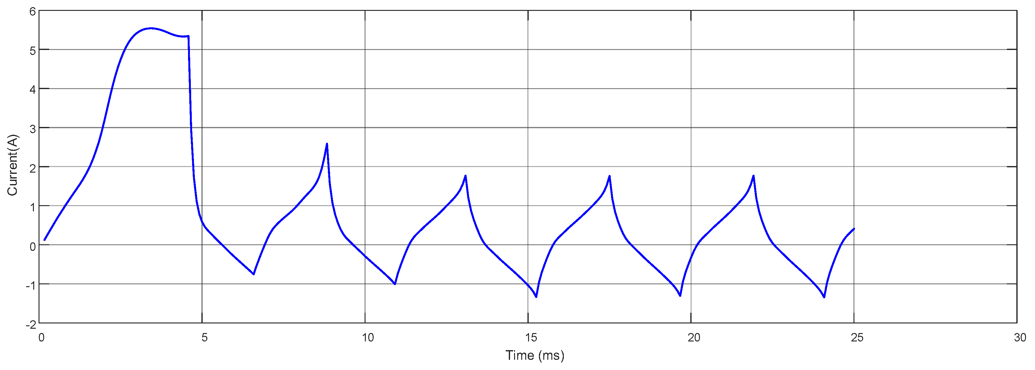
While BLDC motors are typically designed with a three-phase configuration, single-phase BLDC motors are preferred in certain applications due to their lower cost and simpler driver circuitry requirements. Compared to their three-phase counterparts, single-phase BLDC motors offer advantages such as requiring fewer components, having a more compact design, and being more suitable for mass production. However, these motors also have drawbacks, including low starting torque and a tendency to create dead points at specific rotor positions. Therefore, factors such as the magnetic air gap, commutation strategies, and torque performance are critically important in the design of these motors.
In this study, the design process of a single-phase BLDC motor used in combi fan applications is addressed, and the proposed design is evaluated in terms of how it resolves the dead point issue and its impact on overall motor performance.
2.1. Structure and Operating Principle of the Single-Phase BLDC Motor
A single-phase BLDC motor is an electric machine equipped with permanent magnets on the rotor and utilizes electronic commutation instead of the mechanical commutator and brush system used in conventional brushed DC motors [
28]. In order for the rotor to rotate, a rotating magnetic field must be generated within the motor [
29]. To generate this rotating magnetic field, the direction of current must be periodically altered in accordance with the position of the magnets on the rotor. Therefore, single-phase BLDC motors require a driver circuit.
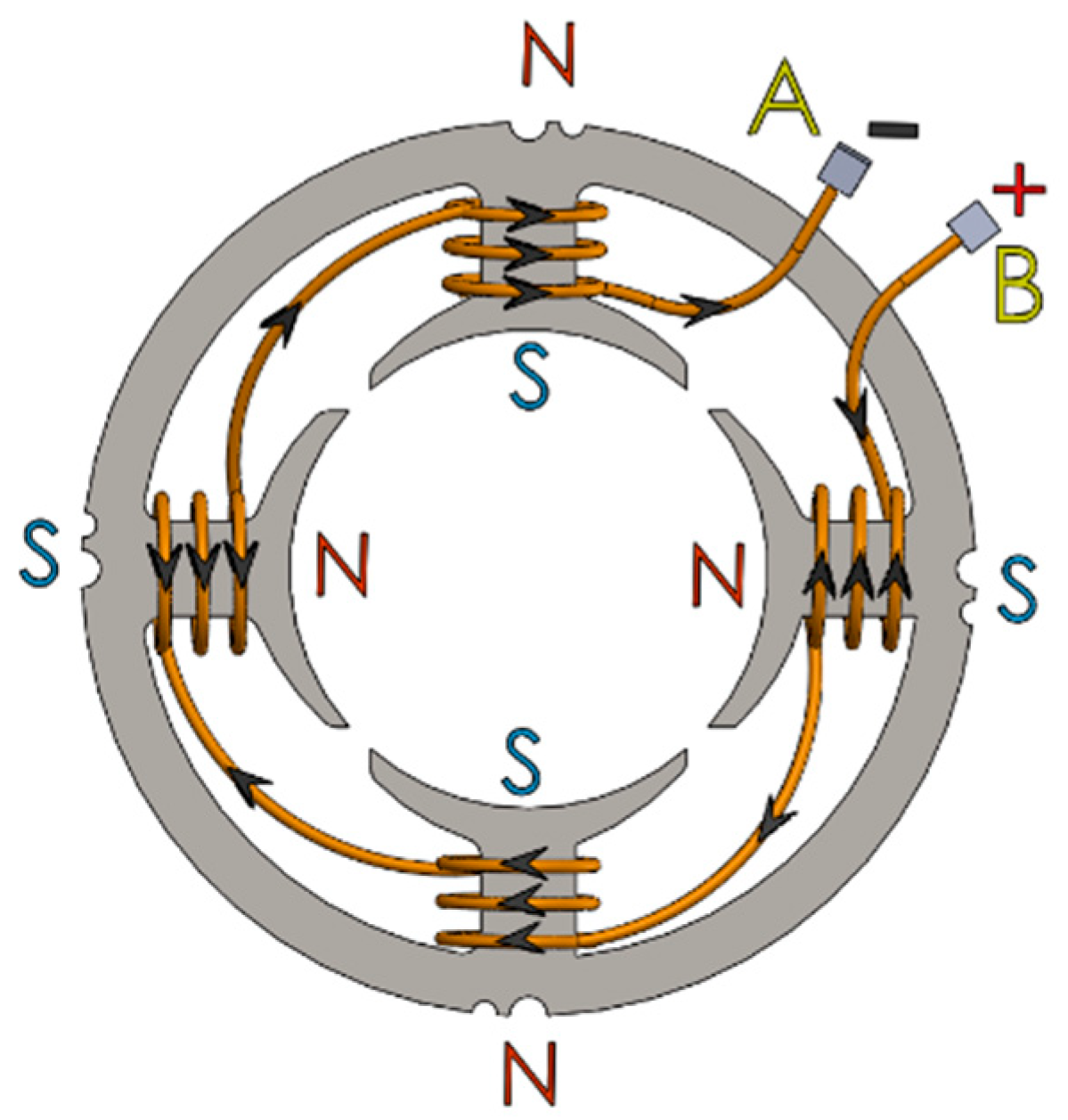
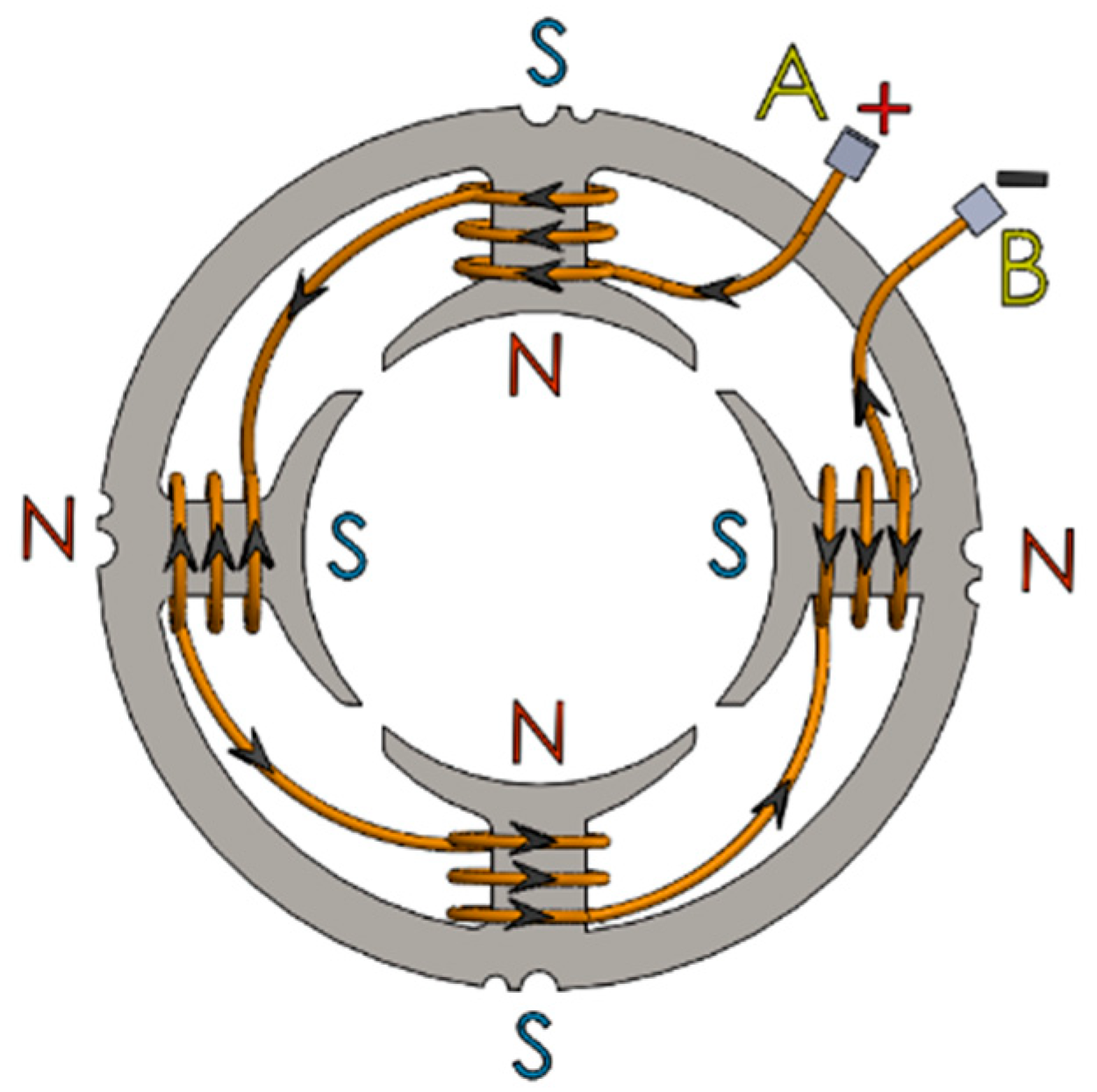
The stator structure of the single-phase, four-pole brushless DC motor is presented in
Figure 1 and
Figure 2. The stator consists of four coils wound using the concentrated winding technique, where each coil forms a magnetic pole, resulting in an overall four-pole magnetic field configuration.
The coils are connected in series. Although the current direction is identical in all windings due to the series connection, the winding directions of successive coils are arranged oppositely in order to obtain the desired alternating magnetic pole sequence around the stator periphery. As a result, an N–S–N–S magnetic pole distribution is established along the stator. The orientation of the magnetic poles is determined based on the conventional right-hand rule, which defines the relationship between the current direction and the resulting magnetic field.
Figure 1 illustrates the winding directions of the coils and the corresponding spatial distribution of the magnetic poles on the stator. As shown in
Figure 2, reversing the direction of the current flowing through the coils leads to a reversal of the stator magnetic field, causing an interchange of the north (N) and south (S) pole positions. When the current direction is periodically reversed at a certain frequency, a spatially time-varying magnetic pole pattern is produced within the stator, giving rise to a rotating magnetic field. The interaction between this rotating magnetic field and the rotor generates electromagnetic torque, thereby enabling the rotational motion of the motor.
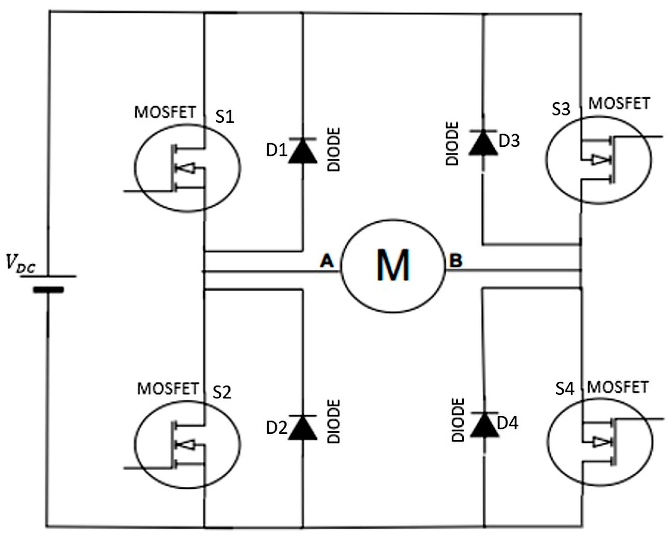
The H-bridge inverter illustrated in
Figure 3 is composed of four power MOSFET switches (S1–S4) along with their antiparallel freewheeling diodes (D1–D4). The switches S1–S4 regulate the direction of the current flowing through the motor winding, thereby controlling the magnetic field established within the motor, which is required for electronic commutation in the single-phase BLDC motor. During operation, diagonal switch pairs (S1–S4 or S2–S3) are turned on to reverse the current direction in the phase winding.
The antiparallel diodes D1–D4 provide a freewheeling path for the inductive winding current when the MOSFETs are turned off. This prevents excessive voltage spikes caused by the winding inductance and ensures safe and reliable operation of the power electronic converter.
Based on the rotor position information obtained from the Hall-effect sensor, current is applied to the motor winding through terminal A or B by means of the single-phase H-bridge circuit shown in
Figure 3. The single-phase BLDC motor is driven using this full-bridge inverter configuration [
30]. Depending on the rotor position, the direction of the current flowing through the H-bridge is reversed, thereby generating a continuously and periodically repeating rotating magnetic field within the stator, as illustrated in
Figure 1 and
Figure 2.
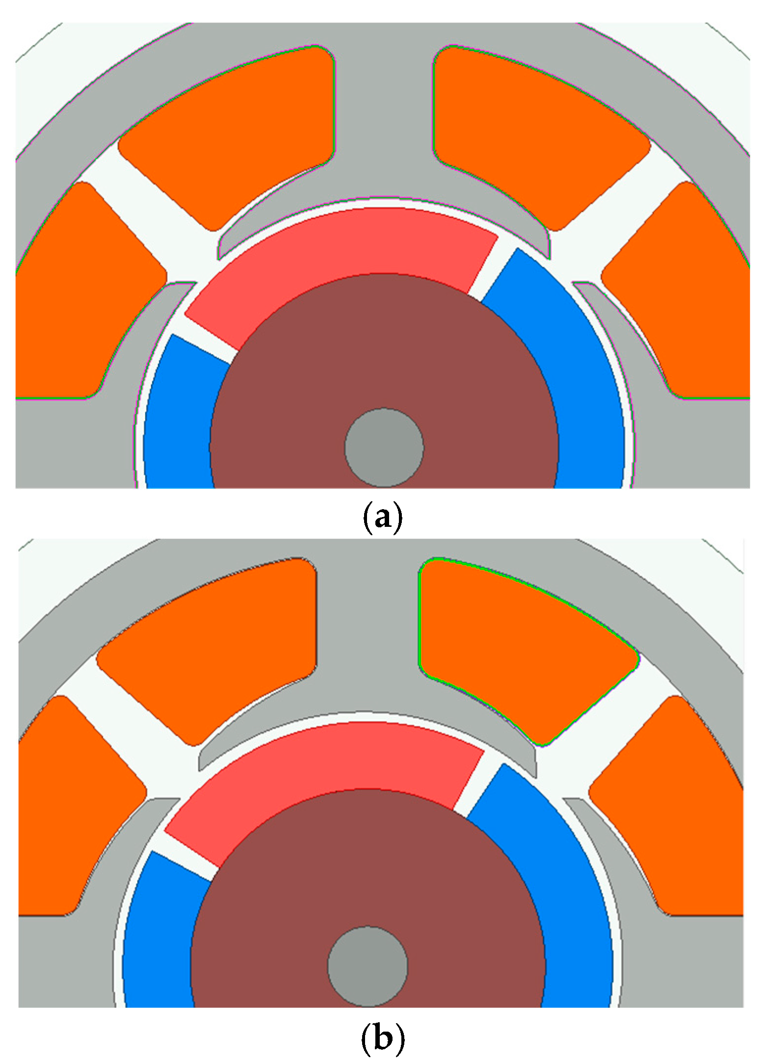
In
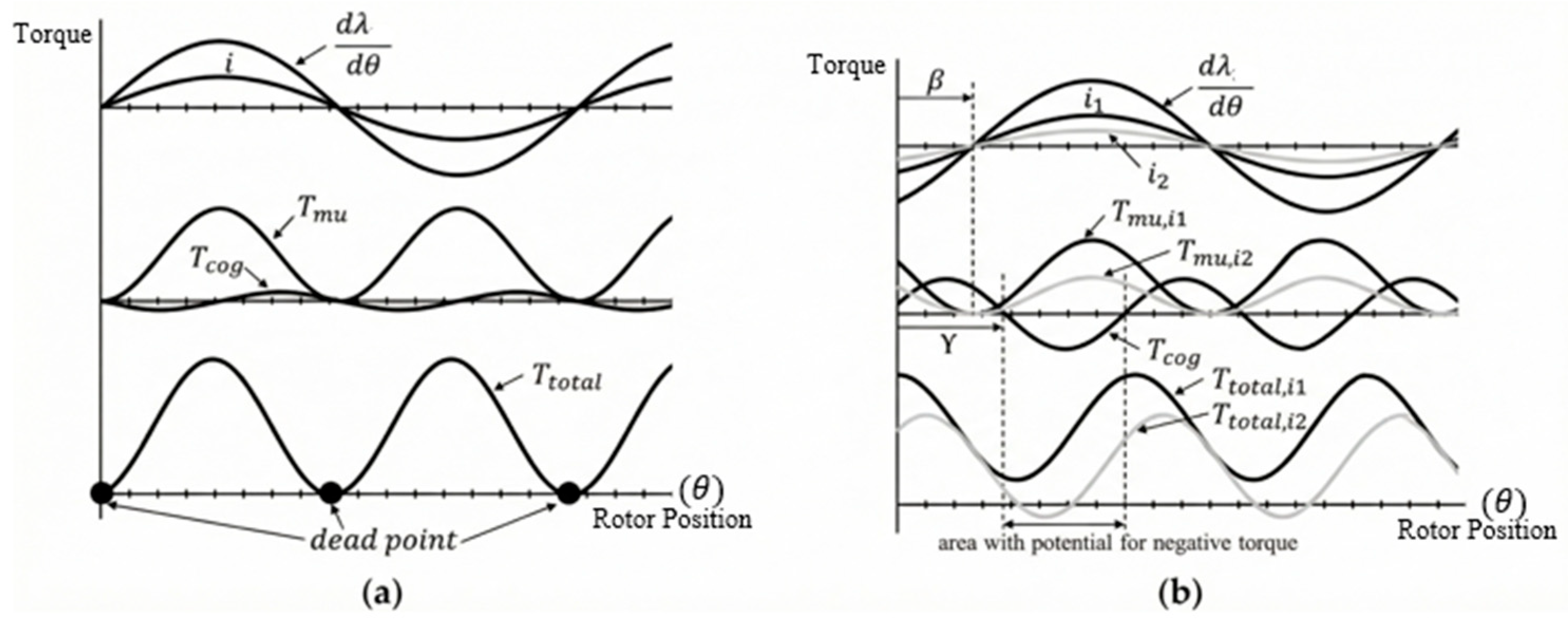
Figure 4a, the dead points occurring in a single-phase BLDC motor with a symmetric air gap are shown. In
Figure 4b, it is observed that the dead point issue is eliminated by applying an asymmetric air gap [
8]. Although the use of an asymmetric air gap can eliminate dead points, it adversely affects the torque and efficiency characteristics of the motor [
11].
In Equation (1),
is mutual torque,
is cogging torque, and
is total torque.
In Equation (2),
is current,
is mutual torque phase angle, angle, θ is position of rotor and
is flux linkage.
In Equation (3), is magnetic flux, is reluctance and is cogging torque phase. Here, denotes the amplitude of the cogging torque.
Equations (1)–(3) are adapted from [
8]. The torque production mechanism of the single-phase BLDC motor is mathematically modeled by Equations (1)–(3). Equation (1) expresses the total instantaneous torque as the superposition of two distinct mechanisms: the active mutual torque, generated by the interaction of current and magnetic flux, and the passive cogging torque, arising from the magnet-iron interaction. The mutual torque, defined in Equation (2), governs the motor’s power output and is directly proportional to the stator current and the spatial rate of change of the flux linkage. Physically, this relationship implies that torque production is maximized when current injection is synchronized with the peak back-EMF. In the context of the proposed asymmetric design, the phase angle β is particularly significant as it represents the shift in the effective flux axis caused by the non-uniform air gap. Finally, Equation (3) characterizes the cogging torque, derived from the principle of minimum reluctance. The dependence on dR/dθ indicates that this torque component exists solely due to the variation of magnetic reluctance with respect to rotor position. By intentionally modifying this reluctance gradient and the resulting phase angle γ through the asymmetric air gap, a specific ‘detent’ torque is created to prevent the rotor from aligning with magnetic dead points when unpowered.
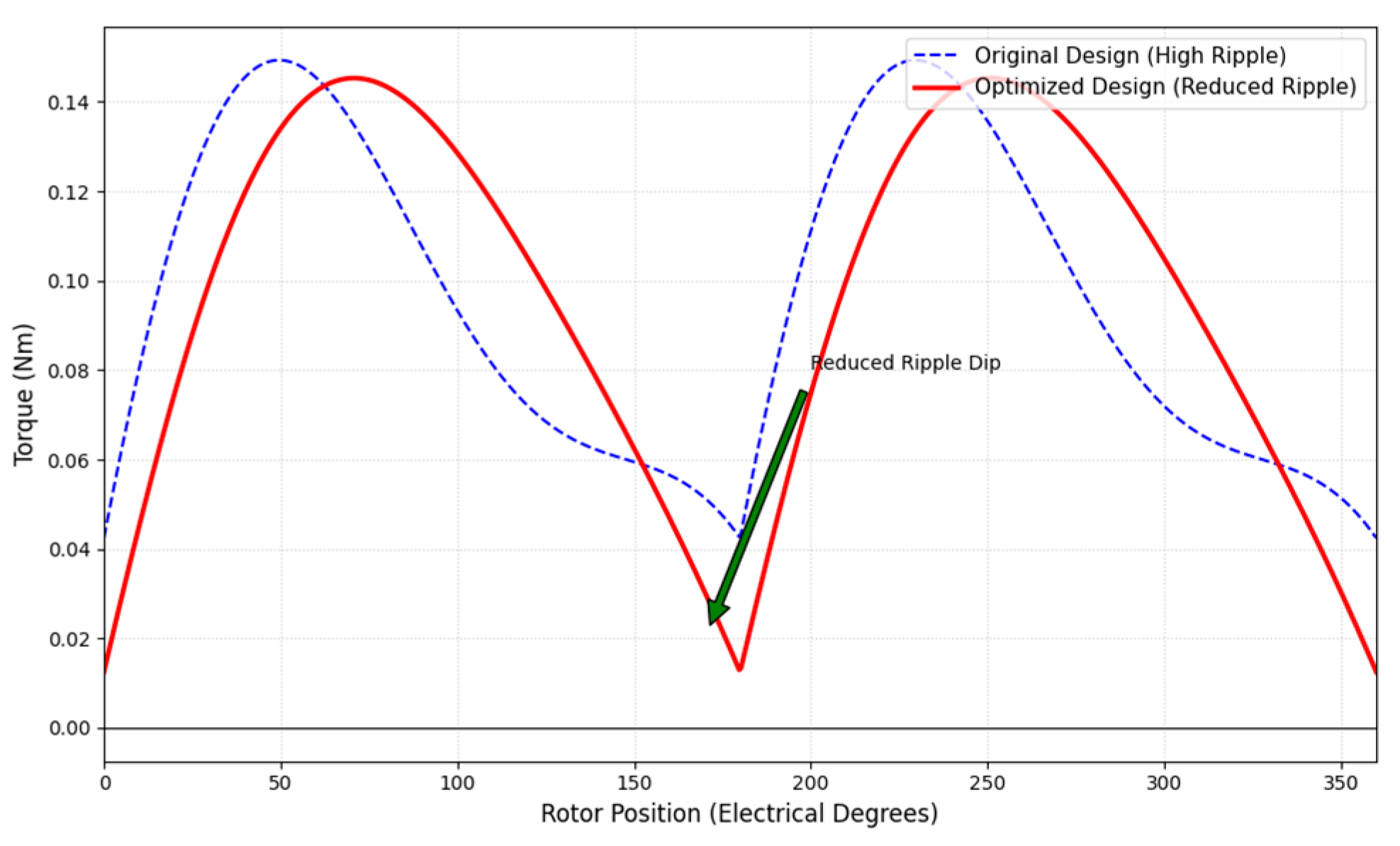
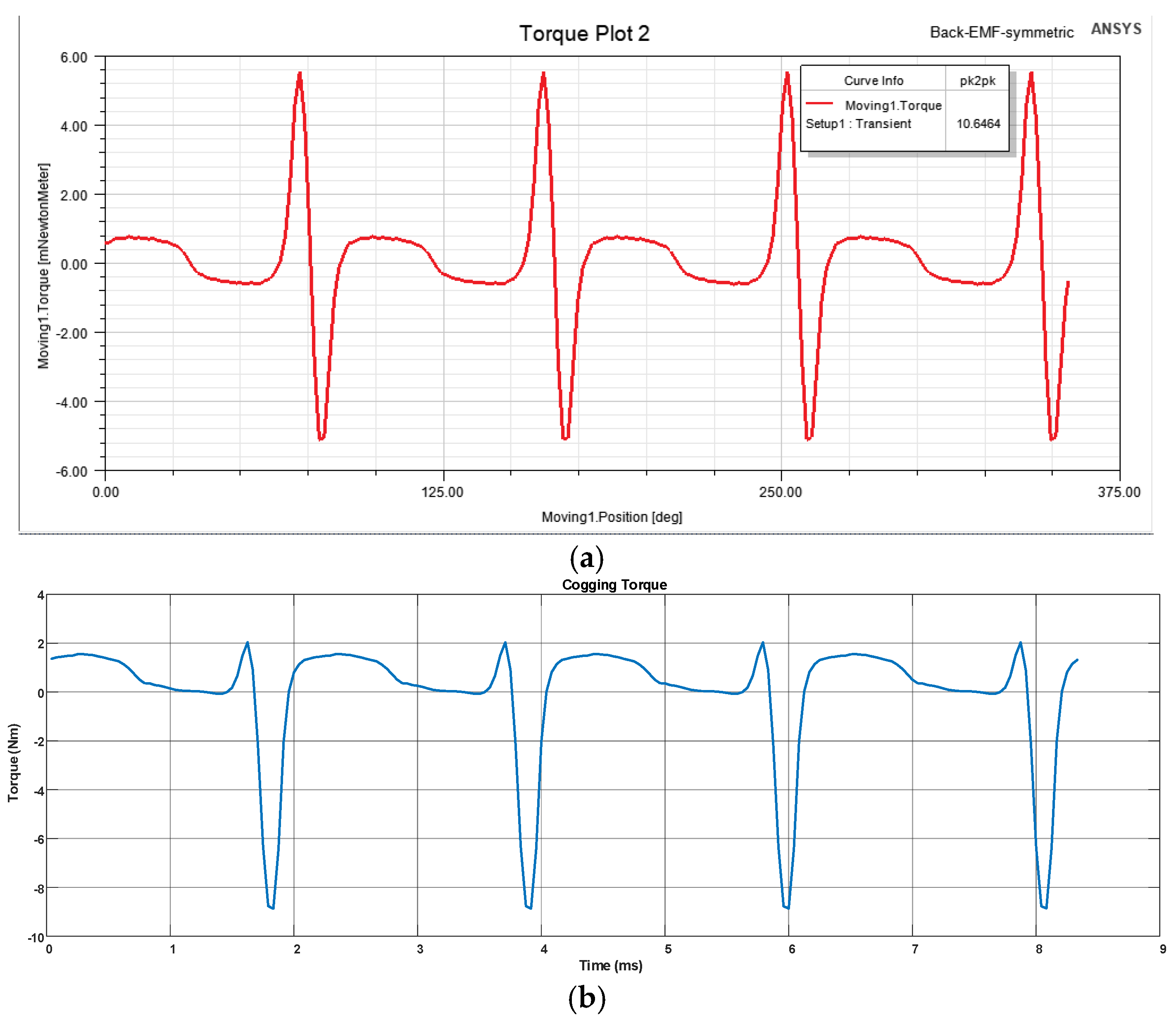
Equation (1) expresses the total electromagnetic torque as the sum of the cogging torque and mutual torque. Equation (2) provides the mutual torque’s mathematical expression. The phase angle γ changes more than the phase angle β due to the reluctance effect caused by the asymmetric air gap variation, as seen in
Figure 4b. This is due to the fact that the rate of change of reluctance with respect to rotor position has a more direct impact on the phase angle γ, as demonstrated by Equation (3). As shown in
Figure 4b, a phase shift between the mutual torque and the cogging torque results from variations in the phase angles γ and β [
8].
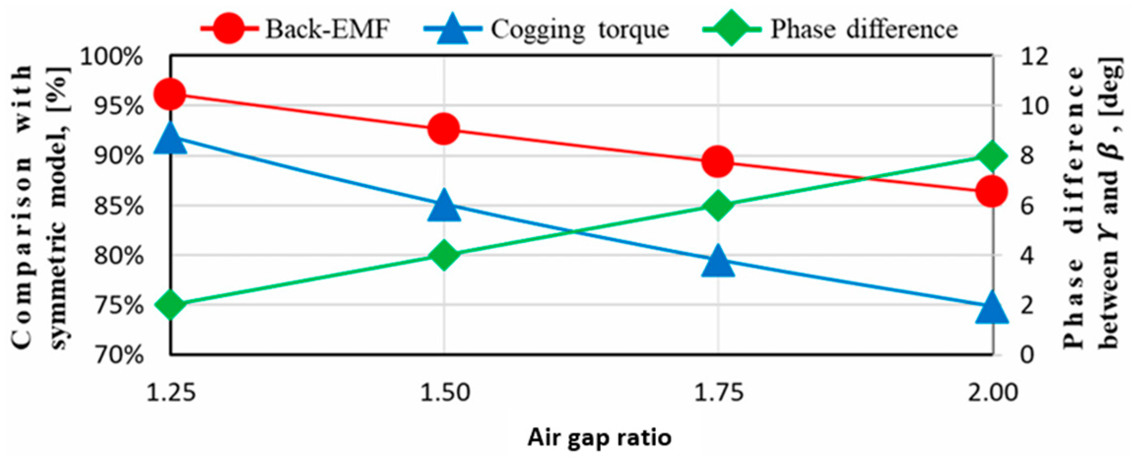
Hongsik Hwang et al. studied the “No-load performance of the conical air gap as a function of length ratio” and obtained the results shown in
Figure 5 [
8]. According to the analysis results, it has been found appropriate to set the air gap ratio to approximately two-to-one [
31].
The relationship between the total electromagnetic torque () defined in Equation (1) and the mechanical output torque () used in the design equations requires clarification. The total electromagnetic torque () represents the instantaneous torque produced by the motor, which consists of two components: the mutual torque () arising from the interaction between the stator current and rotor magnetic field, and the cogging torque () resulting from the variation of magnetic reluctance with rotor position.
The output torque (
) represents the average useful mechanical torque delivered to the load. Under steady-state operating conditions, the relationship between these quantities can be expressed as:
where
is the time-averaged value of
over one electrical cycle, and
accounts for friction and windage losses. Since the cogging torque (
) is a pulsating component with zero average value over a complete electrical cycle, the average output torque primarily depends on the average mutual torque component. Therefore:
In practical motor design, when is negligible compared to (typically less than 5% for small motors), the output torque closely approximates the average total electromagnetic torque. This relationship justifies the use of in the design equations (Equations (4)) as the target mechanical output, while (Equation (1)) describes the instantaneous electromagnetic behavior including torque ripple effects.
2.2. Single-Phase BLDC Motor Design
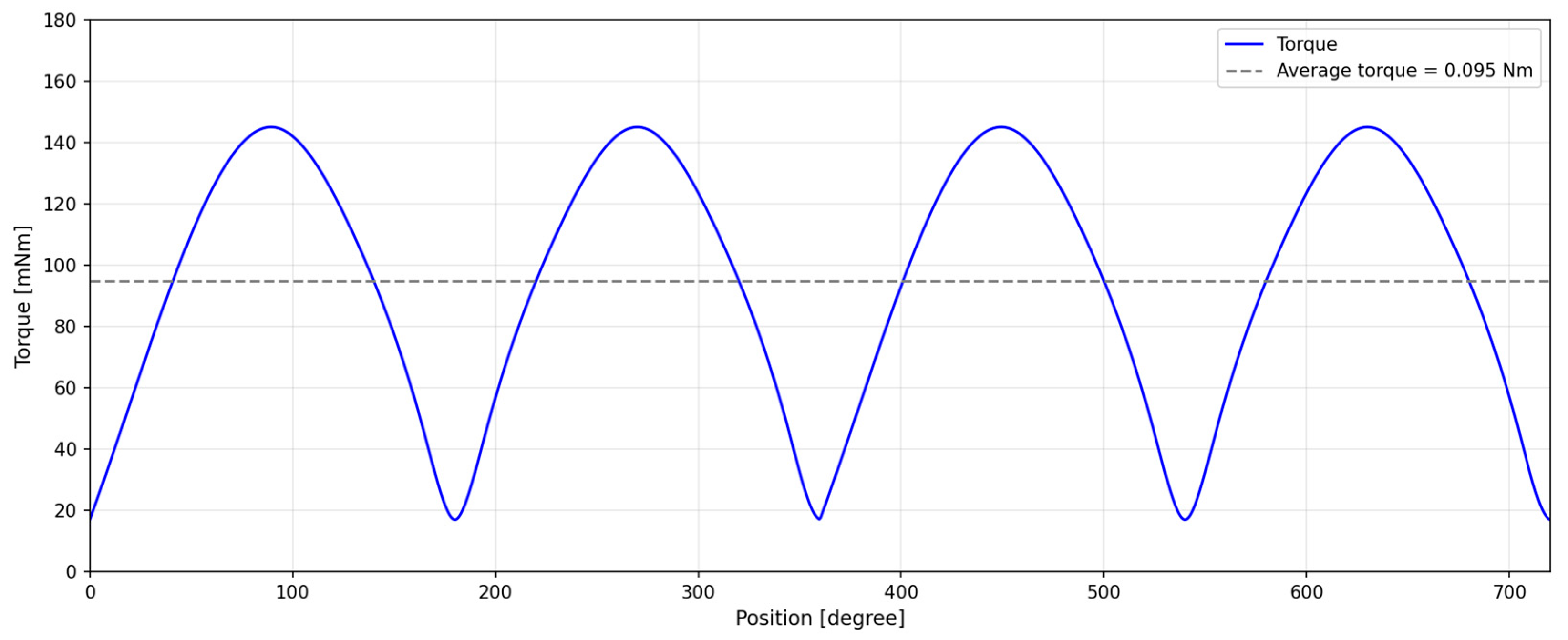
In this study, the combi fan motor is designed to operate at approximately 7200 rpm under a 300 V DC supply, delivering an output power of 95 W and average torque of 0.095 Nm. Within the scope of the study, the step-by-step design process of the single-phase BLDC motor is presented, and the obtained results are compared with ANSYS Maxwell analysis outcomes.
Here is output power, is output torque, is angular velocity, rps is revolutions per second, rpm is revolutions per minute, is input power, is target efficiency, is effective voltage value, is DC voltage value, is voltage drop value, is effective current value. The design process begins by defining the mechanical load requirements imposed by the combi fan application. Equations (6)–(8) determine the required mechanical shaft power based on the target output torque and angular velocity, where the rotational speed is converted to radians per second to ensure unit consistency. Subsequently, Equation (9) estimates the required electrical input power, utilizing the target efficiency as a critical design parameter to account for the anticipated copper, iron, and friction losses. Since the motor is driven by a single-phase H-bridge inverter, the voltage applied to the windings alternates polarity. Therefore, Equation (10) is employed to calculate the effective (RMS) voltage available for torque production; this calculation explicitly considers the voltage drop across the power switches and adjusts the DC bus voltage by a factor of to represent the fundamental component of the applied square-wave voltage. Finally, Equation (11) derives the effective phase current. This parameter physically represents the thermal load on the stator windings and dictates the selection of the conductor wire gauge to ensure safe operation within thermal limits.
In Equation (6), the formulas for calculating the motor’s output power are provided. Using this equation, both the torque value and the motor output coefficient are determined. Equations (7) and (8) present the method for calculating the angular velocity () in radians, where the rotational speed given in revolutions per minute (rpm) is first converted into revolutions per second (rps) by dividing by 60, and the angular velocity is then obtained by multiplying the resulting value by 2π. Prior to starting the design process, once the target efficiency is defined, the input power is calculated using Equation (9).
In order to determine the motor current, the input power must first be calculated, and the voltage level to be applied to the motor must be predetermined. During the current calculation, voltage drops that may occur in the circuit should be taken into account, and these drops should be included in the calculations within reasonable limits. Depending on the structural characteristics of the motor, the effective value of the applied voltage may vary. Particularly in the design of single-phase brushless direct current (BLDC) motors, the applied DC voltage is supplied in the form of positive and negative alternations that change over time according to the rotor position. This means that the effect of the steady DC component must be discounted in the RMS voltage calculation. Therefore, in such motors, when calculating the RMS value of the voltage, it is assumed that the applied DC voltage level is reduced by a factor of √2 and this reduction is incorporated into the calculation [
32]. In line with this approach, the RMS current of the motor can be calculated using Equations (10) and (11).
As can be seen from
Figure 6a, the expression
can be represented by a straight-line equation of the form
In this equation, the constant term is defined as
while the A coefficient is given by
Substituting these coefficients into the flux linkage expression yields
Taking the time derivative of this expression gives
here,
=
, where the electrical angular speed is defined as
. In addition, the maximum flux linkage is defined as
Accordingly, the back electromotive force (
) can be expressed as given in Equation (13).
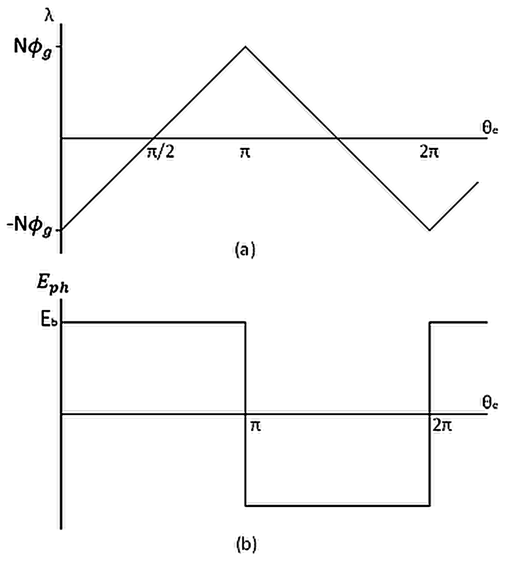
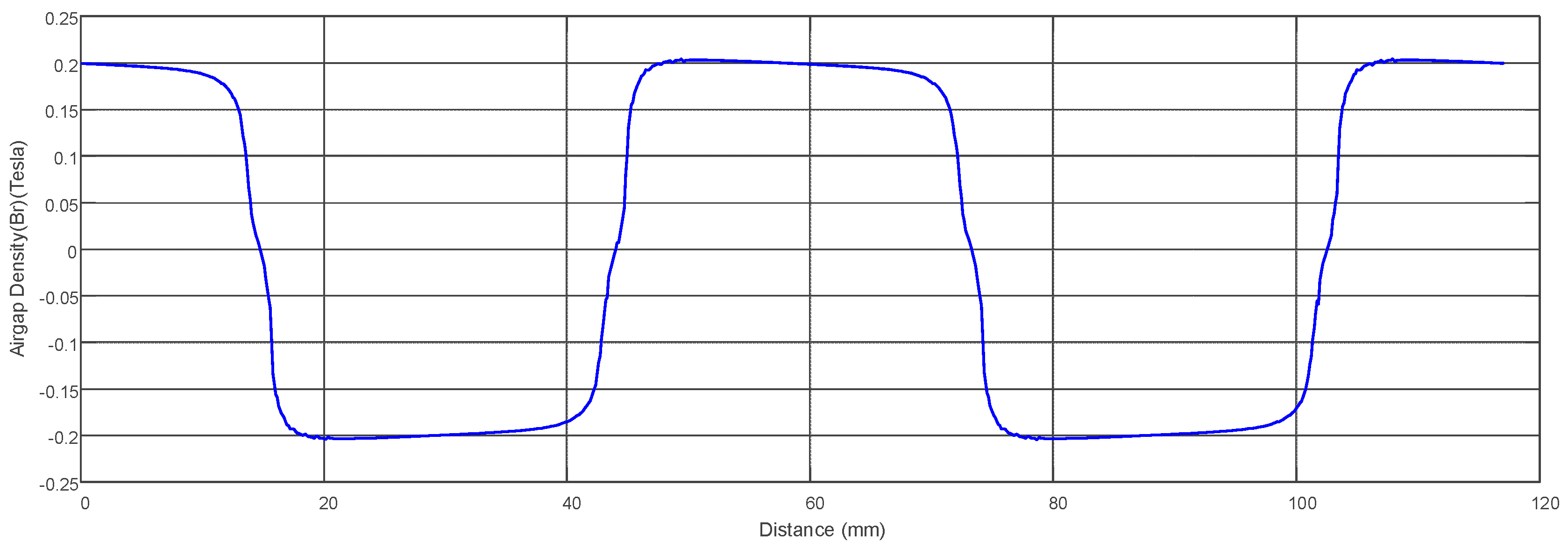
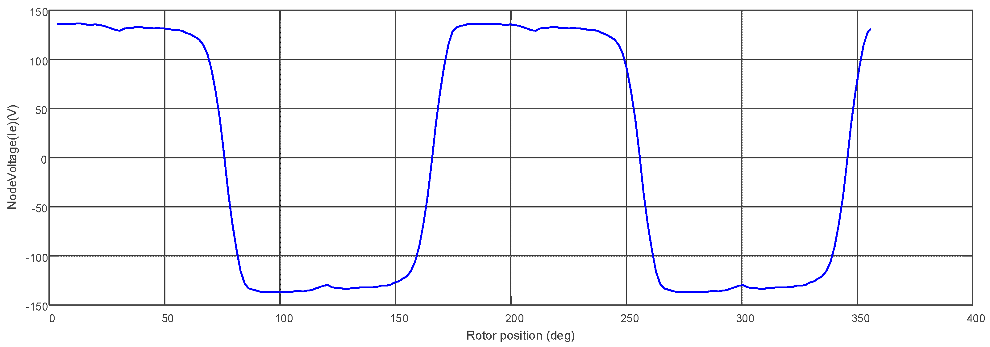
According to Faraday’s law, the back-EMF corresponds to the derivative of the flux linkage waveform. As shown in
Figure 6a, since the flux linkage waveform is triangular, the resulting back-EMF waveform, as illustrated in
Figure 6b, takes the form of a square wave [
33]. Analytically, the back-EMF is expressed in Equation (12). The symbols used in this equation represent the following: λ denotes the flux linkage,
the electrical angular velocity, ωₘ the mechanical angular velocity, and
represents the number of rotor poles. Therefore, based on the linear variation of the flux linkage observed in
Figure 6a, an analytical expression of the flux linkage as a function of the electrical angle is defined. This linear characteristic of the flux linkage waveform indicates that the magnitude of the back electromotive force is directly related to the slope of the waveform. Within the framework of Faraday’s law, the time derivative of this linear flux linkage expression is taken to obtain the phase back-EMF expression, which is presented in Equation (13). The flux linkage expression is given in Equation (14), where
, Nₜₚₕ, and φₚ represent the winding factor, the number of phase effective turns, and the pole flux. Finally, by incorporating the slope factor (
) into the equation, the final form of Equation (15) is obtained.
The physical and magnetic characteristics of the magnetic sheets used in the design of electrical machines are among the fundamental factors that directly affect machine performance. In permanent magnet motors in particular, the magnetic flux density in the air gap is assumed to be a constant value based on the flux density of the magnet material, its magnetic saturation level, and the magnetization properties of the magnetic sheet used. This constant value is employed as a reference parameter in the calculations and is considered a key input in the electromagnetic design of the motor. Numerous experimental studies and performance analyses in the literature have identified appropriate ranges of magnetic flux density recommended for different motor types. These ranges can serve as initial references for similar designs. The expression for calculating the average absolute magnetic flux density in the air gap (
) is given by Equation (16), where D represents the inner diameter of the stator and
L denotes the length of the magnetic core (stack). When the pole flux (
) used in the formula is rearranged using Equation (13), the result is expressed in Equation (17). When the obtained equation is substituted into Equation (15), Equation (18) is obtained.
Electric loading, that is, the linear current density around the (ac) air gap, is defined as the number of ampere-conductors per meter along the stator surface facing the air gap. The mathematical expression of this definition is given in Equation (19). It represents the number of phases, m. By rearranging the current expression and substituting it into Equation (20), Equation (21) is obtained. Finally, the output coefficient G derived in Equation (22), is calculated for the motor to be designed.
The Torque per Rotor Volume (TRV) is defined as the volume-specific torque, or the torque per unit volume. This value will be calculated based on Equation (23).
is output torque,
is the rotor volume. The magnet type used in the design is ferrite, and for rotors with ferrite magnets, a suitable TRV range is between 7 and 14 kNm/m
3 [
34].
During the motor design process, the inner diameter of the stator (D) and stack length (L) must be accurately determined in accordance with the torque value obtained per unit volume. Accordingly, the volumetric expression derived in Equation (24) is used in conjunction with Equations (25)–(27) to calculate the appropriate values of D and L for the motor. In Equation (25), the symbol
is defined as the pole pitch.
represents the number of rotor poles. In Equation (26), the symbol aᵣ represents the aspect ratio defined as the ratio of the laminated core (magnetic stack) length to the stator inner diameter. This geometric design parameter is used to characterize the overall dimensional structure of the motor and is generally selected by considering mechanical layout and space constraints; accordingly, the aspect ratio in motor design is defined as the ratio of the laminated core (magnetic stack) length to the stator inner diameter.
The determination of the number of windings in the motor is based on the back electromotive force (back-EMF) value. The back-EMF refers to the voltage induced in the stator windings as the rotor rotates, in accordance with the motor’s operating principle. This quantity provides direct information about the motor’s magnetization characteristics and winding structure. When the parameter defined in Equation (28) is less than 1, the system operates in motor mode; when it is greater than 1, it operates in generator mode. This parameter represents the ratio between the applied voltage and the back-EMF and plays a critical role in defining the operating regime. Therefore, since the design is based on motor mode operation, a suitable value less than 1 was selected for , and the back electromotive force was calculated by considering approximately half of the supply voltage. In this way, a reasonable design limit was defined based on the assumption that the motor operates under forward supply conditions. Then, using Equation (18), the number of phase effective turns () was obtained. This parameter determines the effect of the winding structure on the electromagnetic torque generated by the motor. The number of windings is a significant design variable that directly affects EMF generation and torque capacity. The calculated value was then divided by the number of stator teeth (Nₛ) using Equation (29), yielding the number of turns per tooth () required to be wound on each tooth.
In the motor design process, the selection of wire diameter is carried out by considering the target current density (J) and the calculated phase current. In this context, the copper cross-sectional area of the wire is calculated by dividing the phase current by the specified current density. The corresponding wire diameter is then selected according to relevant standards, taking into account the motor’s operating temperature and cooling method. Commonly used standards for this purpose include AWG (American Wire Gauge) and SWG (Standard Wire Gauge). However, in special operating conditions—particularly where thermal limits and compact design requirements are critical—non-standard, custom-manufactured copper conductors may also be preferred.
The slot geometries used in motors vary depending on several parameters such as electromagnetic performance, thermal management, and ease of manufacturing. During the design process, calculations are typically based on standard slot profiles defined in the literature. However, in cases where specific performance requirements or application-oriented constraints arise, it may be necessary to model slot structures in a customized manner. In such cases, the slot design must be optimized with respect to multiple criteria, including electromagnetic efficiency, thermal conductivity, and structural integrity.
The physical volume of the windings to be placed in the slots should be determined based on the wire diameter and the number of turns. Therefore, accurate and precise calculation of the slot area is of critical importance for both manufacturability and thermal safety of the motor. The total required area for the windings is calculated based on the targeted number of turns and the selected conductor diameter. The slot area is then obtained by multiplying this winding area by the slot fill factor (
). The slot fill factor is typically a value recommended in the literature and varies depending on the application type. However, parameters such as the type of winding used (e.g., conventional round wire windings or hairpin windings), conductor insulation thickness, insertion technique, and operating temperature of the motor should be considered when determining this factor. Keeping the slot fill factor below one is essential to ensure mechanical flexibility in winding placement and adequate cooling capacity.
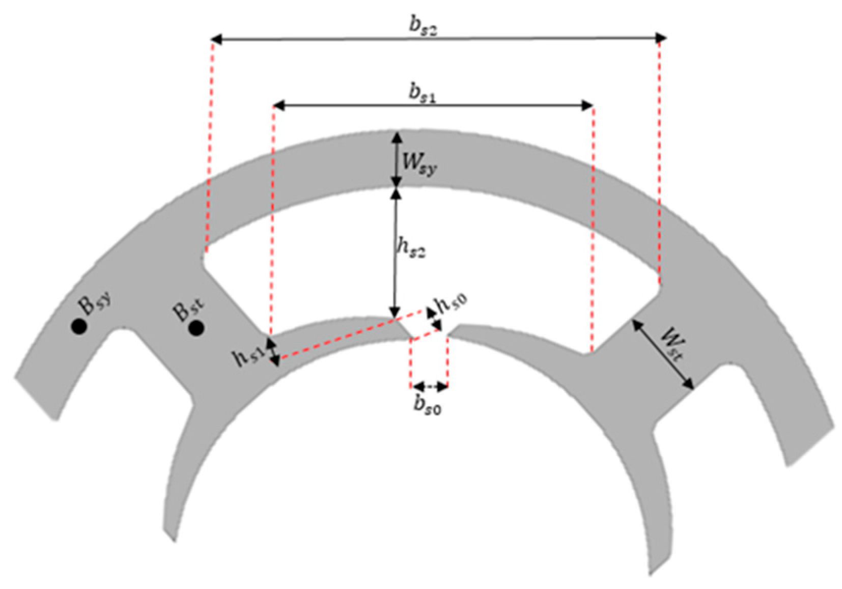
Here is width of stator tooth, is absolute average magnetic flux density in the air gap, is maximum flux density in stator tooth, D is the inner diameter of the stator, is the number of stator teeth, is iron insulation factor, is width of stator yoke, maximum flux density in stator yoke, is slot opening width, is slot bottom width, is slot opening height, is height of tooth shoe, is slot top width, and is the stator slot pitch angle, which is calculated as = 2π/. The term represents the gross winding area of a single coil, and denotes the height of the stator tooth.
As part of the stator design process, dimensional calculations play a critical role, as they directly influence the performance of the magnetic circuit. In these calculations, various geometric parameters are determined based on the magnetic flux density, and the physical dimensions of the stator are defined accordingly. The stator geometry dimensions shown in
Figure 7 are used as a reference for the calculations. To focus specifically on the electromagnetic performance of the proposed topology, the model presented in
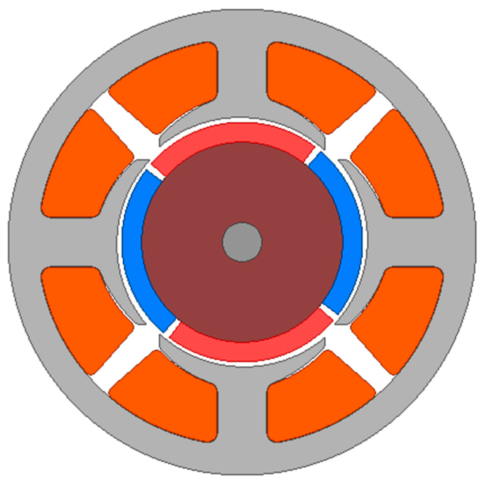
Figure 8 is generated without considering the coil winding process. In practical applications, such stator geometries can be wound either manually or by using an automated segmentation-based winding approach. The appropriate stator dimensions are calculated using Equations (30)–(34). In addition, Equations (32) and (33) are solved simultaneously during the calculation process. The resulting motor dimensions obtained from these calculations are presented in
Table 1.
Figure 8 shows the model of the single-phase BLDC motor created in the ANSYS Maxwell 2D interface. In this design, a conical-shaped asymmetric air gap has been implemented, with a minimum of 0.5 mm and a maximum of 1 mm between the magnet and the air gap.
This air gap configuration effectively eliminates the dead point problem. To reduce cost, ferrite magnets were used in the rotor, which was designed with surface-mounted magnets.
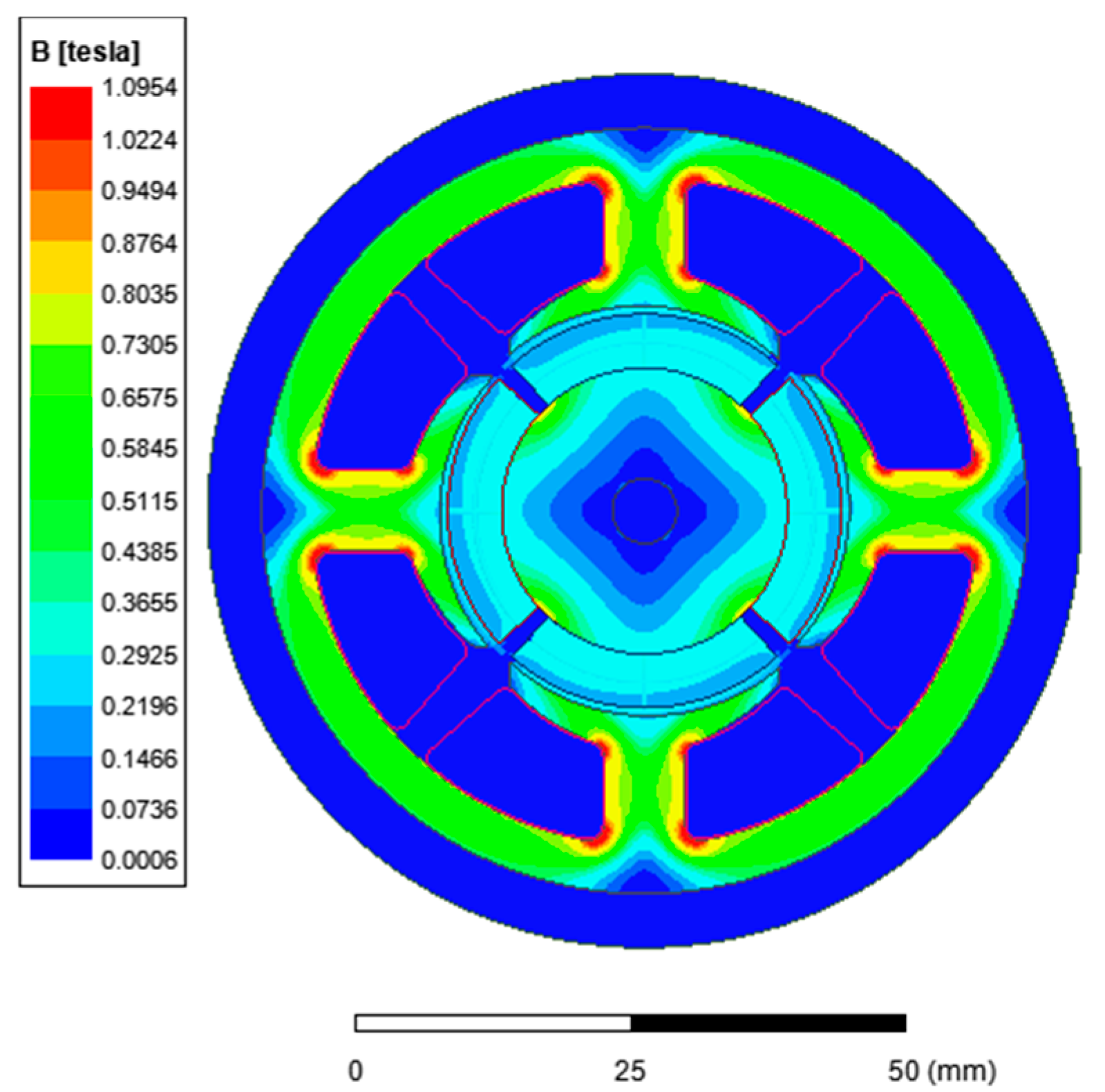
Figure 9 shows the magnetic flux density distribution of the motor. The analysis revealed that magnetic saturation did not occur in the sheet material and that the flux density values in the tooth and yoke regions shown in the figure remained within reasonable limits.
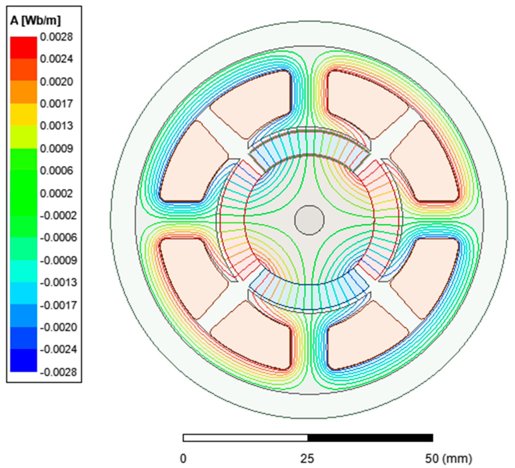
Figure 10 shows the distribution of magnetic flux. It can be observed that the flux lines have a uniform distribution and that no saturation occurs.
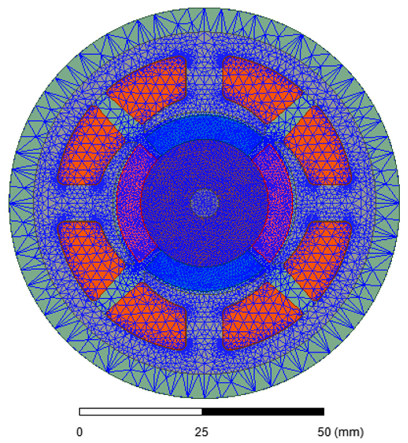
Figure 11 shows the analysis of the designed motor using the finite element method. In analyses performed using the finite element approach, both the number and size of the mesh elements play an important role in determining the accuracy of the results. Figure shows the mesh distribution of the single-phase BLDC motor model used in this study. In regions where flux density changes are critical, a finer mesh containing a greater number of elements is applied. Conversely, areas less sensitive to flux density are modeled with larger mesh elements. This approach increases the accuracy of the simulation while reducing the total computation time.
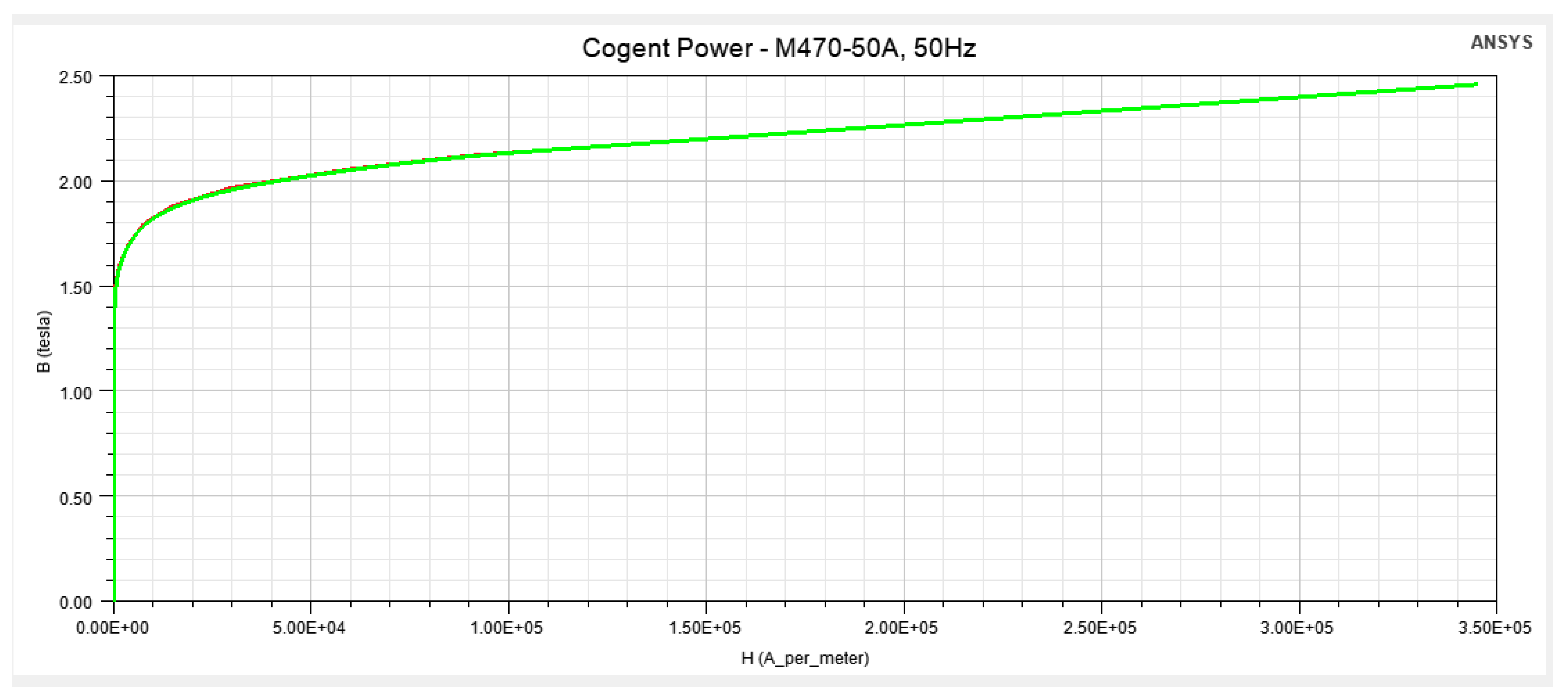
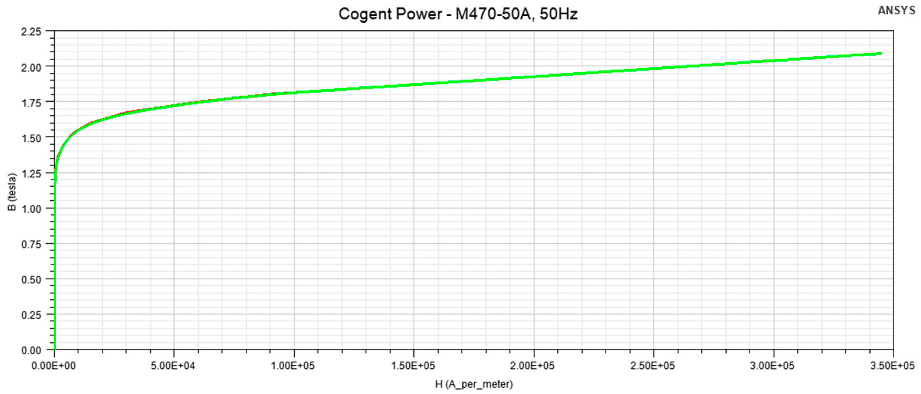
Ferromagnetic laminated steel was used. The employed lamination material is M470-50A, defined for 50 Hz. The M470 lamination material property in ANSYS Maxwell was modified by replacing the original BH curve with a “weakened” BH curve. For this purpose, the magnetic flux density (B) values were reduced by 15%. This reduction represents an empirical approach to model the decrease in effective permeability/flux density after the cutting process. In the literature, similar scaling factors have been used to represent cutting effects, and it has been reported that modifications on the B side have a more dominant impact on the model [
35]. In addition, the stacking factor in the lamination material properties was set to 0.95. The stacking direction was defined as V [
3].
Figure 12 shows the original B–H curve for the M470-50A, 50 Hz electrical sheet metal found in the ANSYS Maxwell library. This curve represents the nonlinear relationship between the magnetic flux density (B) and the magnetic field strength (H) of the material, clearly illustrating its behavior, particularly in the saturation region. In electric motor designs, the BH characteristic of the sheet material has a direct effect on the air gap flux density, magnetic saturation, iron losses, and indirectly on electromagnetic torque production.
Figure 13 shows the BH curve of the M470-50A electrical steel sheet with magnetic flux density weakened by 15%. This weakening process was applied to represent the magnetic insulation layers formed during sheet packaging, stresses caused by mechanical cutting, and post-manufacturing magnetic property losses. This approach is a modeling technique commonly used in the literature that provides results closer to reality in finite element analysis (FEA). With the weakening of the BH curve, the flux density obtained under the same magnetic field strength decreases; this directly affects the air gap flux density, torque production, and iron losses.