Abstract
Image inpainting infers the missing areas of a corrupted image according to the information of the undamaged part. Many existing image inpainting methods can generate plausible inpainted results from damaged images with the fast-developed deep-learning technology. However, they still suffer from over-smoothed textures or textural distortion in the cases of complex textural details or large damaged areas. To restore textures at a fine-grained level, we propose an image inpainting method based on a hierarchical VQ-VAE with a vector credibility mechanism. It first trains the hierarchical VQ-VAE with ground truth images to update two codebooks and to obtain two corresponding vector collections containing information on ground truth images. The two vector collections are fed to a decoder to generate the corresponding high-fidelity outputs. An encoder then is trained with the corresponding damaged image. It generates vector collections approximating the ground truth by the help of the prior knowledge provided by the codebooks. After that, the two vector collections pass through the decoder from the hierarchical VQ-VAE to produce the inpainted results. In addition, we apply a vector credibility mechanism to promote vector collections from damaged images and approximate vector collections from ground truth images. To further improve the inpainting result, we apply a refinement network, which uses residual blocks with different dilation rates to acquire both global information and local textural details. Extensive experiments conducted on several datasets demonstrate that our method outperforms the state-of-the-art ones.
1. Introduction
Previous image inpainting methods have used a learning-free strategy, which can be classified into two groups: diffusion-based approaches and patch-based approaches. The diffusion-based approaches iteratively spread valid information from the outside of the inpainting domain toward the inside based on partial differential equations and variational methods. The patch-based approaches fill in the missing areas with patches from known areas, and the patches should have the most similarity with surrounding known areas of missing regions. However, these methods cannot restore semantic information and complex textural details.
To acquire the semantic information of missing regions, many deep-learning-based methods restore damaged areas using the learned data distribution and semantic information through training on large-scale datasets. They use an encoder–decoder framework to restore damaged regions. To obtain global information on images, some of them apply attention-based modules or transformer blocks in their networks.
For further obtaining fine-grained inpainted results, many two-stage inpainting networks, multistage inpainting networks, or progressive inpainting frameworks are proposed. Two-stage or multistage networks usually first produce coarse inpainted results; for example, they first only restore structural information, edges, or images with a small receptive field. Then, these intermediate results are used as input for the next stage to generate the final result. Progressive inpainting approaches gradually reconstruct missing regions from the boundary to the center of holes.
All the aforementioned learning-based methods use learned data distributions and undamaged parts of images to reconstruct missing parts. However, for large damaged areas or insufficient prior knowledge from existing parts, these methods cannot restore satisfying results. To avoid degradation and better take advantage of prior knowledge from ground truth images, we propose a hierarchical VQ-VAE-based image inpainting method, which can take prior knowledge from ground truth images to promote the image inpainting process. It first trains a hierarchical VQ-VAE with ground truth images to obtain two codebooks and two vector collections. The two codebooks contain prior knowledge from ground truth images, and the two vector collections pass through the decoder of the hierarchical VQ-VAE to generate corresponding high-fidelity outputs. Then, we design an encoder using corresponding damaged images as input to generate two vector collections approximating the two vectors produced before with the help of the two codebooks to generate the inpainted result through the decoder mentioned before. Finally, to further enhance the inpainted result obtained by the hierarchical VQ-VAE, a multidilation-rate inpainting module with different dilation rates is designed to use the output of the hierarchical VQ-VAE as its input to acquire the final inpainted result. The damaged image restored by the hierarchical VQ-VAE and multidilation-rate inpainting module in sequence is shown in Figure 1. The main contributions of this work are as follows:
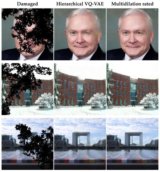
Figure 1.
Image inpainting examples. The first column is damaged images, the second column is images inpainted by the hierarchical VQ-VAE, and the third is images refined by the multidilation-rate inpainting module.
- (1)
- We used ground truth images to train a hierarchical VQ-VAE-based network to update two codebooks and obtain two vector collections, which can generate corresponding high-fidelity outputs through a decoder. The codebooks contain global and local information on ground truth images, so they can provide necessary information for another encoder to restore images;
- (2)
- We introduced a vector credibility mechanism to promote the encoder that uses damaged images as input to generate two vector collections approximating the ones from the ground truth images. Then, they are passed through the decoder to derive inpainted images;
- (3)
- We adopt a refinement network with residual blocks that use convolutional layers with various dilation rates to further enhance the final output.
2. Related Works
Image inpainting has been a hot topic for more than twenty years and can be divided into two classes: learning-based image inpainting and learning-free image inpainting. For learning-based image inpainting, the technology predates the application of deep-learning methods; previous image inpainting methods [1,2,3,4] used learning-free inpainting models. However, these learning-free inpainting models cannot restore semantic information or complex textures, and the current state-of-the-art image inpainting methods apply deep-learning technology. Therefore, in this section, we will introduce and summarize learning-based image inpainting methods.
2.1. Learning-Based Image Inpainting
In recent years, deep-learning methods have been widely used in image inpainting themes, which can extract semantic information and textural details through training on large-scale datasets and then use the learned information to restore damaged images. Pathak et al. [5] first applied a deep-learning method for image inpainting. Pathak et al. [5] utilized an encoder–decoder and trained it with adversarial loss and pixel-wise reconstruction loss. Iizuka et al. [6] introduced both local and global discriminators to improve the method described in [5]. Liu et al. [7] designed a partial convolutional network to fill in irregularly shaped holes, where the partial convolutional layers must contain one more valid pixel. To acquire better inpainted results, they also applied L1 loss, perceptual loss, style loss, and the total variation in the training process. Lian et al. [8] employed a dual-feature encoder to obtain structural and textural features and then used skip connection to guide its corresponding decoder to reconstruct the structural information and textural information. Zeng et al. [9] designed a series of AOT blocks, which splits the kernel convolutional layer into multiple sub-kernel layers with various dilation rates. Among them, the convolutional layers with large receptive fields can acquire global information, and the convolutional layers with small receptive fields can obtain local textural details.
2.2. Transformer- or Attention-Based Image Inpainting
For obtaining global information and strengthening the relationship between distant pixels and inpainting areas, some image inpainting themes [10,11,12,13] apply attention-based inpainting models or transformer blocks [8,14,15,16] to gain global information on known regions, which will be beneficial to the inpainted effect. Yang et al. [11] adopted an attention mechanism to transform patches from known regions to unknown regions. This method uses the local textural loss to ensure that each patch in the missing hole is similar to its corresponding patch in known regions. Yu et al. [10] designed a generative network with some contextual attention layers. The contextual attention layers substitute each patch in the hole for weighted patches outside the hole, which take the similarity as the weight value. Zhao et al. [17] utilized several transformer blocks as encoders and a CNN as a decoder for blind image inpainting. The transformer blocks along with the cross-layer dissimilarity prompt (CDP) obtain the global contextual information and identify contaminated regions. The CNN utilizes the output of the previous transformer blocks as input to further reconstruct the textural details. Liu et al. [18] employed an encoder to convert masked images to non-overlapped patch tokens and then the UQ–transformer handled the patch tokens and obtained the prediction from the codebook; finally, the decoder obtained the final inpainting results. Miao et al. [16] employed an inpainting transformer (ITrans) network to propose an encoder–decoder network together with global and local transformers to inpaint damaged images. The global transformer propagated the encoded global representation from the encoder to the decoder, and the local transform extracted low-level textural details.
2.3. Multistage Image Inpainting
To generate fine-grained textural details, many image inpainting themes [19,20,21] adopt two or more stages to inpaint damaged images. Nazeri et al. [22] used a Canny detector to gain the edges of both damaged images and undamaged images and then an edge generator used this edge information to produce the edges of damaged regions; finally, a completion network obtained the final inpainted result based on the restored edges. Ren et al. [23] used smoothed images without edges to train a structure reconstructor, which generated the structures of the missing areas and then a texture generator employed the reconstructed structures with an appearance flow to generate the final restored images. Huang et al. [24] designed a two-stage approach based on a novel atrous pyramid transformer (APT) for image inpainting. The inpainting method first uses several layers of APT blocks to restore the semantic structures of images and then a dual spectral transform convolutional (DSTC) module is applied to work together with the APT to infer the textural details of damaged areas. Quan et al. [25] proposed a framework that decouples the inpainting process into three stages. The framework first uses an encoder–decoder with a skip connection to obtain a coarse inpainted result and then a shallow network with a small receptive field to restore the local textures. Finally, a U-Net-like architecture with a large receptive field obtains the final inpainted result. Some works [26,27,28] introduced progressive inpainting themes. Zhang et al. [28] used four inpainting modules to fill in missing regions from the boundary of the missing regions to the center. But it cannot restore irregular missing regions. Guo et al. [26] used eight inpainting blocks with the same structure to inpaint corrupted areas in sequence. Each inpainting block fills in a part of the missing areas, and the output of a block is used as the input for the next block during the inpainting process. Li et al. [27] used a series of RFR modules to iteratively fill in damaged areas and update masks simultaneously and then compute the average output of these modules to gain an intermediate output; finally, the intermediate output passed through a series of convolutional layers to obtain the final result.
2.4. VQ-VAEs in Image Inpainting
Recently, VQ-VAEs have been widely used in image generation and image inpainting. Van et al. [29] first proposed the VQ-VAE model and used it in image generation. They encoded ground truth images with an encoder and then quantized them to a vector collection, which comprises a series of discrete vectors. Each vector is replaced by the most similar one in a codebook. After all the vectors in the collection are replaced by the ones in codebooks, the vector collection is passed through a decoder to obtain the corresponding high-fidelity images. Van et al. [29] trained the encoder, the decoder, and the codebook so that the codebook contained information on ground truth images and could be used to generate high-fidelity images through the decoder. To acquire better generated results, Razavi et al. [30] let ground truth images pass through two encoders in sequence, and the quantized vectors were replaced by two codebooks in sequence. Then, the corresponding two vector collections were merged together and passed through a decoder to gain the corresponding high-fidelity images. Peng et al. [31] applied a VQ-VAE-based method for image inpainting. They used ground truth images to train a VQ-VAE model and acquire a codebook containing information on the ground truth images. Then, another VQ-VAE model was used to inpaint damaged images, which used damaged images to produce vector collections, and the vectors in the vector collection were replaced by the vectors in the codebook according to the most similarity, the least similarity, and the th similarity, finally gaining different vector collections. These collections passed through a decoder to obtain k inpainted results. Zheng et al. [32] also trained a VQ-VAE with ground truth images to obtain a codebook containing ground truth image information. Then, this method passed a damaged image through another VQ-VAE encoder to generate a vector collection and then replace the generated vector with the previously generated codebook; after that, the replaced vector was inferred through a transformer. Finally, the decoder generated the restored image.
3. Methodology
We propose an image inpainting framework based on a hierarchical VQ-VAE, and the inpainting framework includes two submodules:
- 1.
- A hierarchical VQ-VAE inpainting module. As shown in Figure 2a, the ground truth images pass through two encoders to gain two vector collections and two codebooks. The vector collections are fed to a decoder to acquire corresponding high-fidelity images. The two codebooks guide the corrupted image to generate two vector collections approximating the previous image and then generate the restored results through the decoder;
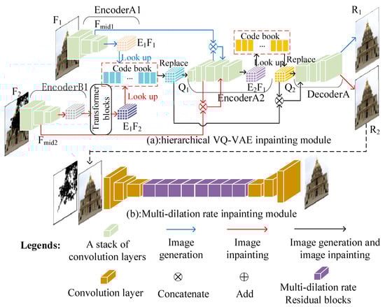 Figure 2. The overview of the network architecture; the output of the hierarchical VQ-VAE is used as the input for the multidilation-rate inpainting module.
 - 2.
- A multidilation-rate inpainting module. As shown in Figure 2b, this module comprises an encoder–decoder framework and residual blocks containing convolutional layers with various dilation rates.
In this section, we introduce the architecture of the VQ-VAE and then demonstrate how the hierarchical VQ-VAE inpainting module inpaints damaged images and finally explain how the multidilation-rate inpainting module further improves the result quality.
3.1. Vector-Quantized Variational Autoencoder (VQ-VAE)
As shown in Figure 2, our image inpainting framework is based on the VQ-VAE model; therefore, we first introduce the architecture of the VQ-VAE. The architecture of the VQ-VAE is shown in Figure 3 and is used in image generation, and we demonstrate it in the following steps:
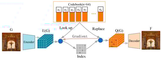
Figure 3.
The architecture of the VQ-VAE.
- 1.
- The ground truth images, denoted as , are fed to an encoder and then flattened into a vector collection, denoted as , which comprises a series of 64-dimensional vectors;
- 2.
- For each vector in , we look up the most similar vector with it among all the vectors in the codebook. Then, the vector in is replaced by the vector in the codebook, as shown in Equation (1).
- 3.
- After all the vectors in are replaced by the vectors in the codebook, becomes another vector collection, denoted as . is passed through a decoder to obtain the high-fidelity images corresponding to the ground truth image, .
To let the VQ-VAE generate high-fidelity images, the encoder, the decoder, and the codebook need to be trained; we define the loss function in Equation (2) to train the encoder and decoder. In Equation (2), is used to train both the encoder and decoder, and is designed to train the encoder, which forces to approximate the codebook, where the operator refers to the stop-gradient operation, and is a hyperparameter controlling the proportion of the loss function.
We also need to update the vectors of the codebook to let the codebook approximate . Instead of adopting the gradient back propagation and loss function, we use the exponential moving average to update codebooks in every training iteration process, and it can be described by the following equations, where denotes the number of vectors in replaced by in the th training iteration. denotes the sum of the vectors in replaced by in the th training iteration, and is a decay parameter.
3.2. Hierarchical VQ-VAE Inpainting Module
The process of the hierarchical VQ-VAE inpainting module about restoring corrupted images can be divided into two steps: training the module with ground truth images and training the module with damaged images. We will discuss it in the following two steps:
- 1.
- Training with ground truth images. The objectives for training the hierarchical VQ-VAE inpainting module with ground truth images are image generation and updating codebooks, which contain global and local information on ground truth images, respectively. The hierarchical VQ-VAE training process is shown in Figure 2a, which adopts a blue arrow and a black arrow to indicate this process. We discuss the process as follows: The ground truth images, denoted as , are fed to EncoderA1, to generate the intermediate output, , and final output, . The vectors in vector collection are replaced by vectors in the codebook and then become another vector collection, , as mentioned in Section 3.1. and pass through EncoderA2 to obtain vector collection , like before. and contain the global information and local details of ground truth images, respectively; they concatenate together and pass through DecoderA to gain high-fidelity images, denoted as . Finally, we train EncoderA1, EncoderA2, and DecoderA and update the codebooks so that they can provide global and local information on ground truths;
- 2.
- Training with damaged images. As mentioned before, the vector collections, and , can generate high-fidelity images, in which the differences with ground truth images are hard to see. Therefore, we try to use damaged images as input to generate two vector collections, which approximate and , and these two vector collections pass through DecoderA to obtain high-fidelity images as the inpainted result. We design EncoderB1, which has a similar architecture with EncoderA1 and uses damaged images as input, to generate the intermediate output, , which approximates . Then, we design the loss function, as shown in Equation (6), to train EncoderA1, forcing to approximate , where denotes the mask, (0 for missing pixels; 1 otherwise), which is down-sampled 4 times, because and both do so. ⨀ denotes the Hadamard product as follows:
In addition, we design a series of transformer blocks to infer the vector collection produced by EncoderB1 and let the inferred vector collection, , approximate , as shown in Figure 2. We can utilize the L1 loss function in Equation (6), but without the mask information, to train EncoderB1 and the transformer blocks to force to approximate . However, the effect after training is not so good; therefore, we design a vector credibility mechanism in the loss function to promote the approximation of . The vector credibility mechanism can be described as follows.
As shown in Figure 2, the training process of the VQ-VAE with ground truth images forces the vectors in the vector collection and the codebook to be close to each other. After the training process, a batch of ground truth images passes through the encoder to generate a vector collection; for each vector in the vector collection, we look up the most similar vector in the codebook to replace it and compute the distance between the vector in the vector collection and the vector in the codebook. We use the maximal distance among the vector collection as a threshold value, and the vector collection replaced by the codebook vectors can represent the batch of ground truth images. After that, when damaged images pass the VQ-VAE, if a vector from the damaged images is a longer distance than the threshold away from the previously replaced vector collection (The vector that is the most similar vector in the previously replaced vector collection is looked up, and the distance is computed.), that vector can be regarded as being far away from the batch of ground truth images, and we add a weight to the vector in the loss function to promote the closeness of that vector to the vector from the ground truth images and vice versa. The details for applying the vector credibility mentioned above to promote the approximation of can be demonstrated in the following steps:
- 1.
- As shown in Figure 2, the ground truth images,, pass through EncoderA1 to generate the vector collection, ; meanwhile, the corresponding damaged images, , pass through EncoderB1 to obtain the vector collection, . We denote as the th vector in . For each , we look up a vector, , which is the closest to in the codebook to take the place of it. We describe this process as follows in Equation (7):
- 2.
- We define the L2 distance between and as the distance between and its corresponding vector in the codebook, where is the most similar vector to in all the vectors in the codebook. We compute the maximal distance among all the vector in vector collection and then denote as the maximal distance as follows in Equation (8):
- 3.
- After all the vectors in have been replaced by vectors in the codebook, becomes another vector collection, . We denote as the th vector in . For each vector in , we look up a vector, , in , which has the most similarity with the vector among all the vectors in . We also define the L2 distance between and as the distance between and . The vector collection contains information on ground truth images; therefore, if is a long distance away from , will have low credibility, and if is a short distance away from , will have high credibility. We let the vector in , which has a longer distance than , have a high weight in the loss function to promote that vector’s closeness to the ground truth images. We design a vector collection, , as having the same weight as . We denote as the th vector in . Each vector in is initialized as follows in Equation (9):
- 4.
- We define the loss function as follows in Equation (10), with a vector credibility mechanism to force to approximate :
Equations (6) and (10) are loss functions to force to approximate and to approximate . If is close to and they are both replaced by vectors in the same codebook, the ground truth images and their corresponding damaged images will obtain the same vector collection, . Futhermore, if is close to , the ground truth images and their corresponding damaged images will gain the same vector collections, and . Finally, and , generated by ground truth images or damaged images, pass through DecoderA and will obtain the same results. From the above-mentioned analysis, if we try to force and , which are generated by damaged images, to approximate the corresponding and , which are produced by ground truth images, the damaged images will obtain high-fidelity images as inpainted results through EncoderB1, EncoderA2, and DecoderA2. In Figure 2, the red arrow and black arrow show the process to inpaint damaged images.
There are two advantages in computing the loss of the vector collection between and . First, although there still exist slight differences in the vectors in and , after training, sometimes, they may all be replaced by the same vectors in the codebook. As a result, the slight differences between the vectors will be removed. Second, in the cases of areas of large damaged regions and little-known information, the codebooks provide a lot of prior information for image inpainting by virtue of their containment of information on undamaged images, which is conducive to the reconstruction of damaged images.
3.3. Multidilation-Rate Inpainting Module
In Section 3.2, we forced to approximate and to approximate . However, there are still differences between and and between and , which cause blurriness or degradation in the result. In this section, we propose a multidilation-rate inpainting module to solve this problem. The architecture of the multidilation-rate inpainting module is shown in Figure 2b. It consists of an encoder, a decoder, and a stack of multidilation-rate residual blocks. Each multidilation-rate residual block has convolutional layers with various dilation rates. The overview of a multidilation-rate residual block is shown in Figure 4. The input feature map is , passing through four convolutional layers with different dilation rates to generate four output feature maps with fewer channels. The feature maps are concatenated as the new feature map, , which has the same size and number of channels as . is passed through a convolutional layer and added by to form the final output, . The convolutional layers in the residual block with high dilation rates have a larger receptive field for global information. The ones with low dilation rates concentrate on local details, which can relieve the blurriness caused by the hierarchical VQ-VAE. Therefore, the multidilation-rate inpainting module can maintain global information and structures from previous modules while maintaining clear textures.
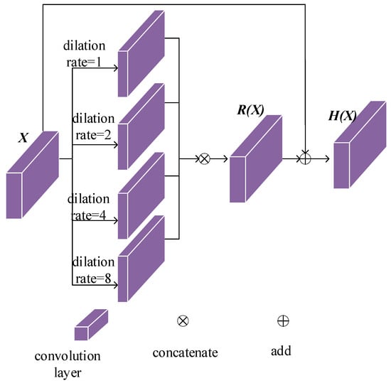
Figure 4.
The overview of a multidilation-rate residual block.
3.4. Loss Functions
To define the loss functions, which are used to train the multidilation-rate inpainting module, we denote as input images, as output images, as ground truth images, and as a mask (0 for missing areas and 1 for known areas). We first define the loss and loss in Equations (11) and (12), respectively, where , and are the channel’s size, the height, and the width of .
We define the perceptual loss, as shown in Equation (13), and define in Equation (14), which set inpainted areas from and others from . In Equation (13), denotes feature maps from the th activation map of the ImageNet-pretrained VGG-19, and we set .
We further introduce the style loss, as shown in Equation (15), where denotes the Gram matrix operation.
We also used the TV loss as follows:
The overall loss for the multidilation-rate inpainting module is as follows:
4. Experiments and Discussion
In this section, we will introduce the implementation details of our framework and the mask generation process. Then, we will compare our method with four state-of-the-art methods. Finally, we will discuss our ablation study.
4.1. Datasets and Implementation Details
Our network architecture is shown in Figure 2, and the number of transformer blocks in Figure 2a is four. The number of multidilation-rate residual blocks in Figure 2b is eight. We use two NVIDIA RTX 3090s to train the network with -sized images and masks with a batch size equal to six. The model is optimized using an Adam optimizer with and because the Adam optimizer combines the advantages of momentum and RMSprop and because its effectiveness has been verified by a large number of deep neural networks, especially transformers.
In this work, three public datasets, which are widely used for image inpainting tasks, are adopted to evaluate the proposed model, including Places2 [33], CelebA [34], and Paris StreetView [35]. In the hierarchical VQ-VAE inpainting module, the ground truth and the corresponding damaged images are from the same image datasets; therefore, the codebook generated by the ground truth images can provide useful information to restore damaged images.
We design a program to draw masks with a certain proportion of the elements filled with the integer 1 (integer 0 for damaged pixels and integer 1 for undamaged pixels). The program first draws a mask image filled with the integer 1 and picks a pixel, , at random to set it at 0. Then, the program chooses a pixel, , in four adjacencies of to become 0; after that, a pixel, , in the 4-neighborhood of , is also set at 0. We repeat this process until the proportion of 0s reaches the threshold. We produce masks from proportions of 0s from 10% to 60%. We generate 200 mask images for each certain proportion of 0s. Therefore, we totally generate masks. We show some mask images in Figure 5.
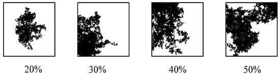
Figure 5.
Mask examples with different ratios.
4.2. Comparisons
4.2.1. Qualitative Comparisons
We compare our method with four state-of-the-art methods developed in the last 4 years: FRRN [26], AOT [9], ITrans [16], and LG [25]. Figure 6, Figure 7 and Figure 8 show the quantitative comparisons of our method with four others for Places2, CelebA, and Paris StreetView.
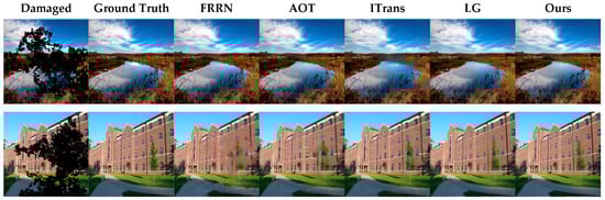
Figure 6.
Comparison for Places2.
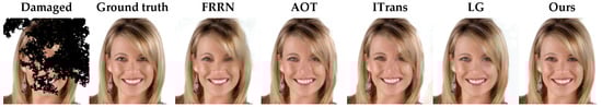
Figure 7.
Comparison for CelebA.
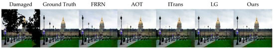
Figure 8.
Comparison for Paris StreetView.
From the second row in Figure 6, our method can maintain more textural details of the wall and windows than LG, AOT, and FRRN. In the first row in Figure 6, our method obtains the object’s integrity better than AOT and ITrans. As shown in Figure 7, our method can obtain a better hair texture than FRRN, AOT, and ITrans. As shown in Figure 8, our method can acquire the correct colors and textures of the grass and building better than the other four methods.
4.2.2. Quantitative Comparisons
We also compare our approach quantitatively, in terms of the structural similarity index (SSIM) [36], peak signal-to-noise ratio (PSNR), Fréchet inception distance (FID) [37], and learned perceptual image patch similarity (LPIPS) [38], with the four aforementioned methods. Table 1, Table 2 and Table 3 give the quantitative results obtained with different ratios of irregular masks for Paris StreetView, Places2, and CelebA, respectively. According to these data, our method outperforms the other four methods.

Table 1.
Quantitative comparison for Paris StreetView.
Table 2.
Quantitative comparison for Places2.
Table 3.
Quantitative comparison for CelebA.
4.3. Ablation Studies
4.3.1. Evaluating the Performance of Multidilation-Rate Inpainting Module
To evaluate the effectiveness of the multidilation-rate inpainting module in our network, we design ablation studies, which compare only the hierarchical VQ-VAE and the whole network. The quantitative comparisons are shown in Table 4 and Table 5 in terms of the PSNR and SSIM for Paris StreetView. The qualitative comparison is shown in Figure 9.
Table 4.
Comparison between the whole network and only the hierarchical VQ-VAE in terms of PSRN.
Table 5.
Comparison between the whole network and only the hierarchical VQ-VAE in terms of SSIM.
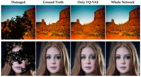
Figure 9.
Comparison between the whole network and only the hierarchical VQ-VAE.
4.3.2. Contribution of Different Dilation Rates in the Multidilation-Rate Residual Block
The multidilation-rate residual block with various dilation rates is a part of the multidilation-rate inpainting module. The multidilation-rate residual block adopts convolutional layers with dilation rates of 1, 2, 4, and 8 to acquire both global and local information to restore damaged images. To evaluate the contribution of the combination of convolutional layers with various dilation rates, we conducted four groups of ablation studies at single dilation rates, which are 1, 2, 4, and 8. The four groups of ablation studies are compared for our method, which combines dilation rates of 1, 2, 4, and 8 in residual blocks. The comparison results are shown in Table 6 in terms of the mask ratio of 30–40% for Paris StreetView. From Table 6, the combination of dilation rates 1, 2, 4, and 8 outperforms the other four inpainting themes, which just adopt a single dilation rate.
Table 6.
Comparison of our method with other methods, which adopt a single dilation rate. ↑ means the higher, the better; ↓ means the lower, the better.
5. Conclusions
In this paper, we propose an image inpainting network architecture, which comprises two modules: a hierarchical VQ-VAE module and a multidilation-rate inpainting module. The hierarchical VQ-VAE module uses ground truth images as input to obtain two codebooks and two vector collections through training. The vector collections are passed through a decoder for high-fidelity outputs corresponding to the ground truth images. Then, we design an encoder similar to the hierarchical VQ-VAE module, as well as a series of transformer blocks to infer damaged images with the help of the two codebooks, and a vector credibility mechanism to generate two vector collections approximating the aforementioned ones. The collections obtain high-fidelity outputs as the inpainted result. To relieve blurriness and to improve the final quality, we also designed a multidilation-rate inpainting module. Extensive quantitative and qualitative comparisons demonstrate the superiority of our approach in obtaining inpainting results.
Meanwhile, we also found some problems in the experiment. Our image inpainting approach needs to adopt masks as a direction to indicate the damaged areas of corrupted images. However, in many cases, it is difficult to accurately identify damaged areas, and the process for indicating damaged areas of masks is time-consuming. At present, some image inpainting methods do not require masks to restore damaged images, and these methods are called “blind image inpainting”. In the future, we will improve our approach to let inpainting themes obtain satisfactory inpainted results without masks.
Author Contributions
C.L.: conceptualization, methodology, software, formal analysis, investigation, data curation, writing—original draft preparation, writing—review and editing, and visualization. D.X.: software, investigation, resources, data curation, writing—review and editing, supervision, project administration, and funding acquisition. K.C.: resources, writing—review and editing, and visualization. All authors have read and agreed to the published version of the manuscript.
Funding
This research was supported in part by the National Natural Science Foundation of China, grants number 62162068 and 62061049, in part by the Yunnan Province Ten Thousand Talents Program and Yunling Scholars Special Project, grant number YNWR-YLXZ-2018-022, and in part by the Joint Fund of the Yunnan Provincial Science and Technology Department–Yunnan University’s “Double First Class” Construction, grant number 2019FY003012.
Data Availability Statement
Data are contained within the article.
Conflicts of Interest
The authors declare no conflicts of interest.
References
- Shen, J.; Kang, S.H.; Chan, T.F. Euler’s elastica and curvature-based inpainting. SIAM J. Appl. Math. 2003, 63, 564–592. [Google Scholar] [CrossRef]
- Criminisi, A.; Pérez, P.; Toyama, K. Region filling and object removal by exemplar-based image inpainting. IEEE Trans. Image Process. 2004, 13, 1200–1212. [Google Scholar] [CrossRef] [PubMed]
- Chan, T.F.; Shen, J. Nontexture Inpainting by Curvature-Driven Diffusions. J. Vis. Commun. Image Represent. 2001, 12, 436–449. [Google Scholar] [CrossRef]
- Kawai, N.; Sato, T.; Yokoya, N. Image inpainting considering brightness change and spatial locality of textures and its evaluation. In Proceedings of the Advances in Image and Video Technology: Third Pacific Rim Symposium, PSIVT 2009, Tokyo, Japan, 13–16 January 2009; Proceedings 3. Springer: Berlin/Heidelberg, Germany, 2009; pp. 271–282. [Google Scholar]
- Pathak, D.; Krahenbuhl, P.; Donahue, J.; Darrell, T.; Efros, A.A. Context encoders: Feature learning by inpainting. In Proceedings of the IEEE Conference on Computer Vision and Pattern Recognition, Las Vegas, NV, USA, 27–30 June 2016; pp. 2536–2544. [Google Scholar]
- Iizuka, S.; Simo-Serra, E.; Ishikawa, H. Globally and locally consistent image completion. ACM Trans. Graph. ToG 2017, 36, 1–14. [Google Scholar] [CrossRef]
- Liu, G.; Reda, F.A.; Shih, K.J.; Wang, T.C.; Tao, A.; Catanzaro, B. Image inpainting for irregular holes using partial convolutions. In Proceedings of the European Conference on Computer Vision (ECCV), Munich, Germany, 8–14 September 2018; pp. 85–100. [Google Scholar]
- Lian, J.; Zhang, J.; Liu, J.; Dong, Z.; Zhang, H. Guiding image inpainting via structure and texture features with dual encoder. Vis. Comput. 2023, 1–15. [Google Scholar] [CrossRef]
- Zeng, Y.; Fu, J.; Chao, H.; Guo, B. Aggregated contextual transformations for high-resolution image inpainting. IEEE Trans. Vis. Comput. Graph. 2022, 29, 3266–3280. [Google Scholar] [CrossRef] [PubMed]
- Yu, J.; Lin, Z.; Yang, J.; Shen, X.; Lu, X.; Huang, T.S. Generative image inpainting with contextual attention. In Proceedings of the IEEE Conference on Computer Vision and Pattern Recognition, Salt Lake City, UT, USA, 18–23 June 2018; pp. 5505–5514. [Google Scholar]
- Yang, C.; Lu, X.; Lin, Z.; Shechtman, E.; Wang, O.; Li, H. High-resolution image inpainting using multi-scale neural patch synthesis. In Proceedings of the IEEE Conference on Computer Vision and Pattern Recognition, Honolulu, HI, USA, 21–26 July 2017; pp. 6721–6729. [Google Scholar]
- Song, Y.; Yang, C.; Lin, Z.; Huang, Q.; Li, H.; Kuo, C.C.J. Contextual-based image inpainting: Infer, match, and translate. In Proceedings of the European Conference on Computer Vision (ECCV), Munich, Germany, 8–14 September 2018; pp. 3–19. [Google Scholar]
- Xiang, H.; Min, W.; Wei, Z.; Zhu, M.; Liu, M.; Deng, Z. Image inpainting network based on multi-level attention mechanism. IET Image Process. 2024, 18, 428–438. [Google Scholar] [CrossRef]
- Esser, P.; Rombach, R.; Ommer, B. Taming transformers for high-resolution image synthesis. In Proceedings of the IEEE/CVF Conference on Computer Vision and Pattern Recognition, Nashville, TN, USA, 20–25 June 2021; pp. 12873–12883. [Google Scholar]
- Zheng, C.; Cham, T.J.; Cai, J.; Phung, D.Q. Bridging global context interactions for high-fidelity image completion. In Proceedings of the IEEE/CVF Conference on Computer Vision and Pattern Recognition, New Orleans, LA, USA, 18–24 June 2022; pp. 11512–11522. [Google Scholar]
- Miao, W.; Wang, L.; Lu, H.; Huang, K.; Shi, X.; Liu, B. ITrans: Generative image inpainting with transformers. Multimed. Syst. 2024, 30, 21. [Google Scholar] [CrossRef]
- Zhao, H.; Gu, Z.; Zheng, B.; Zheng, H. Transcnn-hae: Transformer-cnn hybrid autoencoder for blind image inpainting. In Proceedings of the 30th ACM International Conference on Multimedia, Lisboa, Portugal, 10–14 October 2022; pp. 6813–6821. [Google Scholar]
- Liu, Q.; Tan, Z.; Chen, D.; Chu, Q.; Dai, X.; Chen, Y.; Liu, M.; Yuan, L.; Yu, N. Reduce information loss in transformers for pluralistic image inpainting. In Proceedings of the IEEE/CVF Conference on Computer Vision and Pattern Recognition, New Orleans, LA, USA, 18–24 June 2022; pp. 11347–11357. [Google Scholar]
- Qiu, J.; Gao, Y.; Shen, M. Semantic-SCA: Semantic structure image inpainting with the spatial-channel attention. IEEE Access 2021, 9, 12997–13008. [Google Scholar] [CrossRef]
- Zeng, Y.; Lin, Z.; Lu, H.; Patel, V.M. CR-fill: Generative image inpainting with auxiliary contextual reconstruction. In Proceedings of the IEEE/CVF International Conference on Computer Vision, Montreal, QC, Canada, 10–17 October 2021; pp. 14164–14173. [Google Scholar]
- Wang, T.; Ouyang, H.; Chen, Q. Image inpainting with external-internal learning and monochromic bottleneck. In Proceedings of the IEEE/CVF Conference on Computer Vision and Pattern Recognition, Nashville, TN, USA, 20–25 June 2021; pp. 5120–5129. [Google Scholar]
- Nazeri, K.; Ng, E.; Joseph, T.; Qureshi, F.; Ebrahimi, M. Edgeconnect: Generative image inpainting with adversarial edge learning. arXiv 2019, arXiv:1901.00212. [Google Scholar]
- Ren, Y.; Yu, X.; Zhang, R.; Li, T.H.; Liu, S.; Li, G. Structureflow: Image inpainting via structure-aware appearance flow. In Proceedings of the IEEE/CVF International Conference on Computer Vision, Seoul, Republic of Korea, 27 October–2 November 2019; pp. 181–190. [Google Scholar]
- Huang, M.; Zhang, L. Atrous Pyramid Transformer with Spectral Convolution for Image Inpainting. In Proceedings of the 30th ACM International Conference on Multimedia, Lisboa, Portugal, 10–14 October 2022; pp. 4674–4683. [Google Scholar]
- Quan, W.; Zhang, R.; Zhang, Y.; Li, Z.; Wang, J.; Yan, D.-M. Image inpainting with local and global refinement. IEEE Trans. Image Process. 2022, 31, 2405–2420. [Google Scholar] [CrossRef] [PubMed]
- Guo, Z.; Chen, Z.; Yu, T.; Chen, J.; Liu, S. Progressive image inpainting with full-resolution residual network. In Proceedings of the 27th ACM International Conference on Multimedia, Nice, France, 21–25 October 2019; pp. 2496–2504. [Google Scholar]
- Li, J.; Wang, N.; Zhang, L.; Du, B.; Tao, D. Recurrent feature reasoning for image inpainting. In Proceedings of the IEEE/CVF Conference on Computer Vision and Pattern Recognition, Seattle, WA, USA, 13–19 June 2020; pp. 7760–7768. [Google Scholar]
- Zhang, H.; Hu, Z.; Luo, C.; Zuo, W.; Wang, M. Semantic image inpainting with progressive generative networks. In Proceedings of the 26th ACM International Conference on Multimedia, Seoul, Republic of Korea, 22–26 October 2018; pp. 1939–1947. [Google Scholar]
- Van Den Oord, A.; Vinyals, O. Neural discrete representation learning. Adv. Neural Inf. Process. Syst. 2017, 30, 6309–6318. [Google Scholar] [CrossRef]
- Razavi, A.; Van den Oord, A.; Vinyals, O. Generating diverse high-fidelity images with vq-vae-2. Adv. Neural Inf. Process. Syst. 2019, 32. [Google Scholar] [CrossRef]
- Peng, J.; Liu, D.; Xu, S.; Li, H. Generating diverse structure for image inpainting with hierarchical VQ-VAE. In Proceedings of the IEEE/CVF Conference on Computer Vision and Pattern Recognition, Nashville, TN, USA, 20–25 June 2021; pp. 10775–10784. [Google Scholar]
- Zheng, C.; Song, G.; Cham, T.J.; Cai, J.; Phung, D.Q.; Luo, L. High-quality pluralistic image completion via code shared vqgan. arXiv 2022, arXiv:2204.01931. [Google Scholar]
- Zhou, B.; Lapedriza, A.; Khosla, A.; Oliva, A.; Torralba, A. Places: A 10 million image database for scene recognition. IEEE Trans. Pattern Anal. Mach. Intell. 2017, 40, 1452–1464. [Google Scholar] [CrossRef] [PubMed]
- Liu, Z.; Luo, P.; Wang, X.; Tang, X. Deep learning face attributes in the wild. In Proceedings of the IEEE International Conference on Computer Vision, Santiago, Chile, 7–13 December 2015; pp. 3730–3738. [Google Scholar]
- Doersch, C.; Singh, S.; Gupta, A.; Sivic, J.; Efros, A.A. What makes paris look like paris? ACM Trans. Graph. 2012, 31, 103–110. [Google Scholar] [CrossRef]
- Wang, Z.; Bovik, A.C.; Sheikh, H.R.; Simoncelli, E.P. Image quality assessment: From error visibility to structural similarity. IEEE Trans. Image Process. 2004, 13, 600–612. [Google Scholar] [CrossRef] [PubMed]
- Heusel, M.; Ramsauer, H.; Unterthiner, T.; Nessler, B.; Hochreiter, S. Gans trained by a two time-scale update rule converge to a local nash equilibrium. Adv. Neural Inf. Process. Syst. 2017, 30. [Google Scholar] [CrossRef]
- Zhang, R.; Isola, P.; Efros, A.A.; Shechtman, E.; Wang, O. The unreasonable effectiveness of deep features as a perceptual metric. In Proceedings of the IEEE Conference on Computer Vision and Pattern Recognition, Salt Lake City, UT, USA, 18–23 June 2018; pp. 586–595. [Google Scholar]
Disclaimer/Publisher’s Note: The statements, opinions and data contained in all publications are solely those of the individual author(s) and contributor(s) and not of MDPI and/or the editor(s). MDPI and/or the editor(s) disclaim responsibility for any injury to people or property resulting from any ideas, methods, instructions or products referred to in the content. |
© 2024 by the authors. Licensee MDPI, Basel, Switzerland. This article is an open access article distributed under the terms and conditions of the Creative Commons Attribution (CC BY) license (https://creativecommons.org/licenses/by/4.0/).