Abstract
This manuscript proposed a compact slipring based on inductive power transfer (IPT) technology for multi-axis robot manipulators. Compared with conventional solutions, the minimum axial length of the proposed magnetic coupling assembly in the IPT based slipring makes it possible to integrate in-robot joint actuators (electrical motors) with high power and torque densities. Additionally, the voltage transfer characteristic of the wireless slipring system is investigated to provide stable and reliable output voltage in the presence of arbitrary motor speeds and load conditions. A 100-W slipring prototype is designed for a practical three-axis robot arm. The simulation and experimental results clearly verify the system feasibility and effectiveness. The maximum efficiency of 90.3% at an 800 kHz operating frequency is achieved.
1. Introduction
Multi-axis robot manipulators can move fast with high accuracy and reliability, as well as replace humans in high-risk and highly repetitive work, such as in high temperatures and harsh environments that pose a threat to human health. Therefore, they are widely applied in welding, painting, handing, grinding, and polishing, etc.
The power cable is a conventional and widely-used method to transfer electrical power for all robot joint actuators (e.g., permanent magnet synchronous motor, PMSM), as shown in Figure 1. Its major shortcoming is the restriction of the angle of rotation. Additionally, there is the risk of the cable becoming twisted, thereby resulting in disconnection. These problems can be solved by using mechanical sliprings. Mechanical wear and tear, however, are inevitable between the stationary brush and the rotating metallic ring, which will cause significant temperature to rise and electric spark [1]. This means that potential safety hazards, such as low power supply reliability, high maintenance costs, and limited lifetime, are all pending issues, which restrict its application.
Figure 1.
The methods of transferring electrical power between different robot joint actuators, e.g., power cable, mechanical slipring, and wireless slipring.
The wireless power transfer (WPT) technique [2,3,4,5] is a promising solution method due to its outstanding advantages of no exposed electrical and mechanical contacts between the power transmitter (primary) side and the receiver (secondary) side. For a wireless slipring assemble, the contactless magnetic coupler is essential and critical [6,7,8,9,10,11,12,13,14,15,16,17]. A coaxial inductive power transfer (IPT) based wireless slipring, as shown in Figure 2a, has been developed by PowerbyProxi Ltd. and installed as a trial for wind turbine pitch control [11]. In such a design, the stationary primary is fixed to a housing, while the rotor secondary is mounted on the motor rotor shaft by non-magnetic and non-conductive material (e.g., plastic or fiber glass). Additionally, A. Abdolkhani et al. [13] proposed a face-to-face IPT-based slipring as shown in Figure 2b. Both above manufactures, however, suffer from low coupling coefficient, thereby resulting in limited power transfer capability. In [14,15], an improved coupling design method is proposed by optimizing the structure of ferrite cores. In addition, a sandwiched wireless slipring system with double stators shown in Figure 2c is presented in [16,17], which can improve the coupling factor by 24.6% [16]. Furthermore, the output power is increased by four times and the ferrite cores can be omitted at the rotor secondary side compared with the sliprings shown in Figure 2a,b.
Figure 2.
Conventional wireless sliprings. (a) Coaxial, (b) face-to-face, and (c) sandwiched layout.
The electrical motors are usually designed to be short and thick in order to obtain a low-speed high-torque characteristic in the applications of quadruped robotics and multi-axis robotic arms. For the conventional IPT couplers, however, long axial length in mechanical structures makes them difficult to integrate into motors with high power and torque densities. This paper proposed a coaxial and coplanar wireless slipring configuration with minimum axial length. A practical three-axis robotic manipulator is designed. More specifically, Section 2 introduces the proposed wireless slipring and analyzes the voltage transfer characteristic of the IPT-based slipring system. The theoretical analysis is validated through a 100-W IPT-based slipring system at 800 kHz in Section 3. Section 4 concludes the contribution of this paper.
2. System Structure and Circuit Analysis
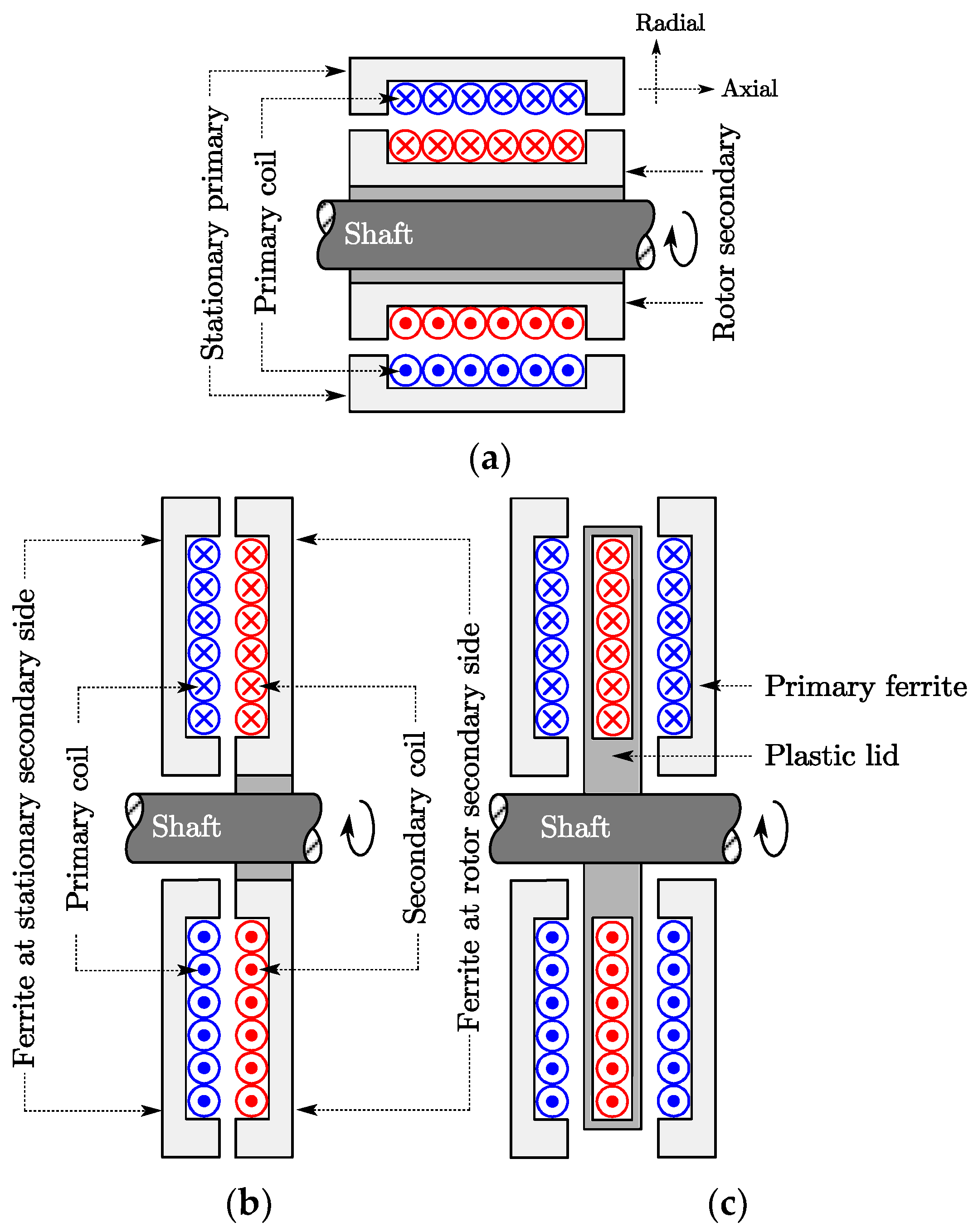
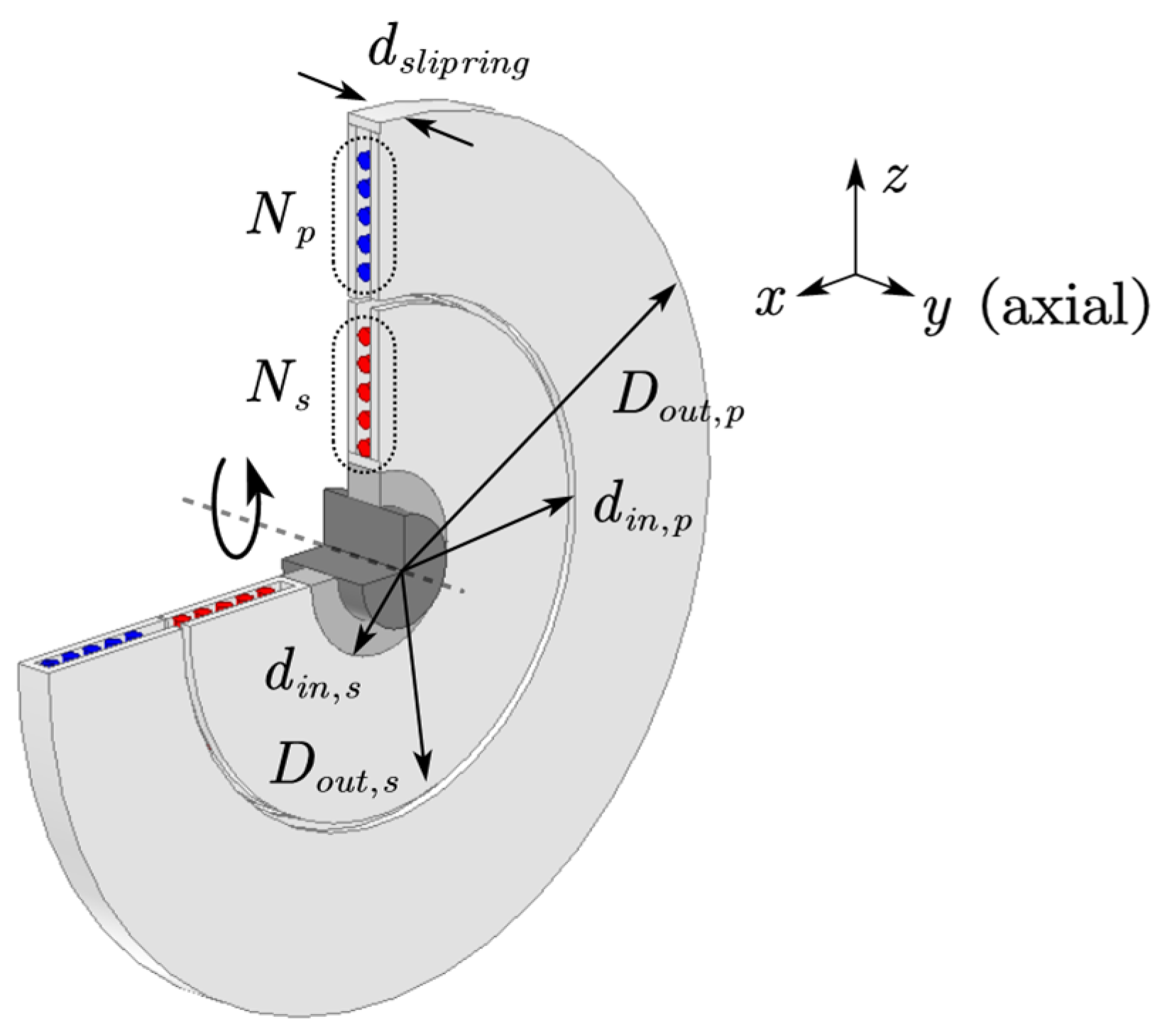
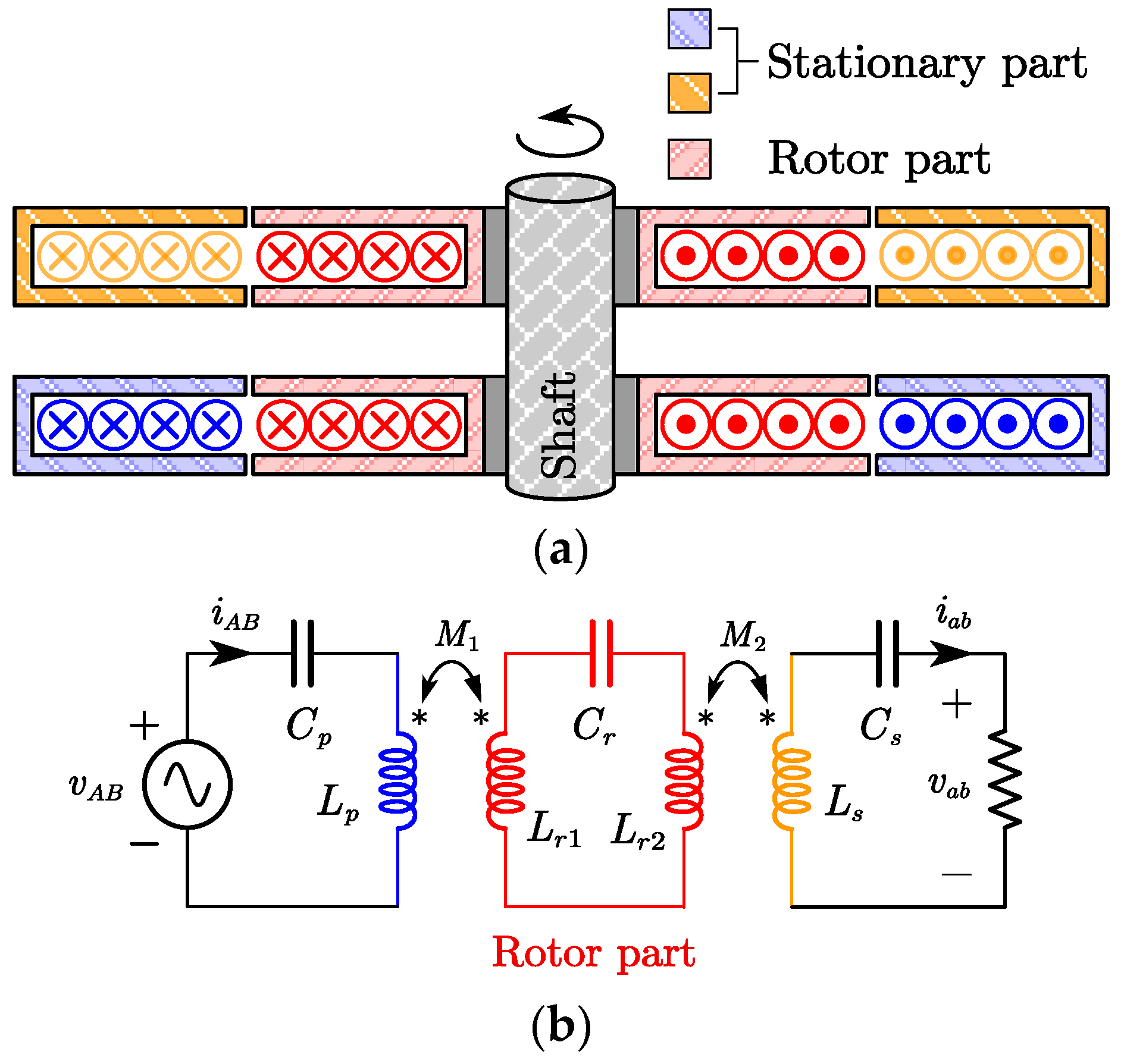
2.1. Mechanical Structure of the Proposed Wireless Slipring
The proposed IPT-based wireless slipring in this paper is shown in Figure 3. It composes a magnetic coupler, compensation networks at both primary and secondary sides, and a high-frequency inverter and a rectifier. Among them, the three-dimensional finite element method (3D FEM) model of the magnetic coupling assembly is shown in Figure 4. Compared with the conventional configurations shown in Figure 2, the stationary primary and the rotor secondary are coaxial and coplanar. This means that the minimum axial length is its outstanding advantage in the mechanical structure.
Figure 3.
The proposed IPT-based wireless slipring system.
Figure 4.
3D FEM model of the proposed wireless slipring.
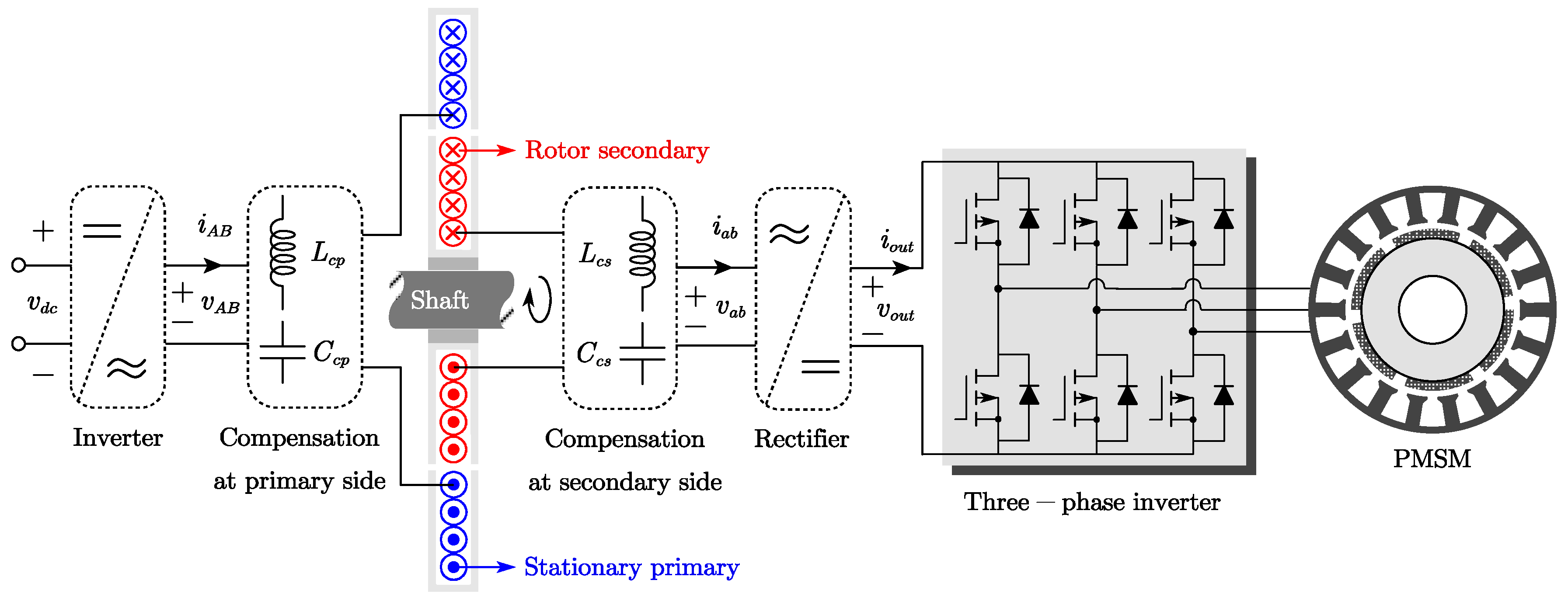
2.2. Circuit Analysis
From Figure 3, the proposed IPT-based wireless slipring system can be modeled as Figure 5a. Here, the wireless slipring has the essence of a loosely coupled transformer (or an IPT coupler). The single-phase H-bride inverter and full-wave diode rectifier are applied. The most widely-used SS (Series–Series) compensation topology [2,3,4] is adopted to improve system power transfer capability and decrease voltage–ampere (VA) rating. The self-inductances of the IPT coupler are represented by , for the primary coil, and , for the secondary coil. M is the mutual inductance. and represent the compensation capacitors at the primary and secondary sides, respectively. A frequency domain equivalent circuit is adopted and only the fundamental component is considered in this paper for simplicity. In this way, the SS compensated wireless slipring system is further derived as Figure 5b. Here, the RMS value of the input voltage is given by ( represents the mean value of the input DC voltage) and the equivalent load on the secondary side is set as ( is the load resistance). Additionally, one defines
here, represents the system operating frequency.
Figure 5.
(a) An IPT-based slipring with SS compensation topology and (b) its equivalent circuit.
In this paper, the IPT-based wireless slipring is applied to drive permanent magnet synchronous motors (PMSM) in the robotic arm, as shown in Figure 3. So, the constant DC output voltage (e.g., 24 V or 48 V) with independent rotor speeds and load conditions should be designed.
According to the Kirchhoff’s voltage theorem, the output voltage of Figure 5b is
The input impedance is given by
From Equation (4), when
the load-independent output voltage can be achieved, and is simplified as
Substituting Equation (6) into Equation (7), also equals
Then, the output power is expressed as
Additionally, under the resonant condition of Equation (6), system input impedance can be deduced as
From (10), the input impedance is inductive at any load conditions. It means ZVS (zero voltage switching) soft switching operation is achieved for the MOSFET-based H-bridge inverter, which will decrease its switching losses.
3. Design and Experimental Evaluations
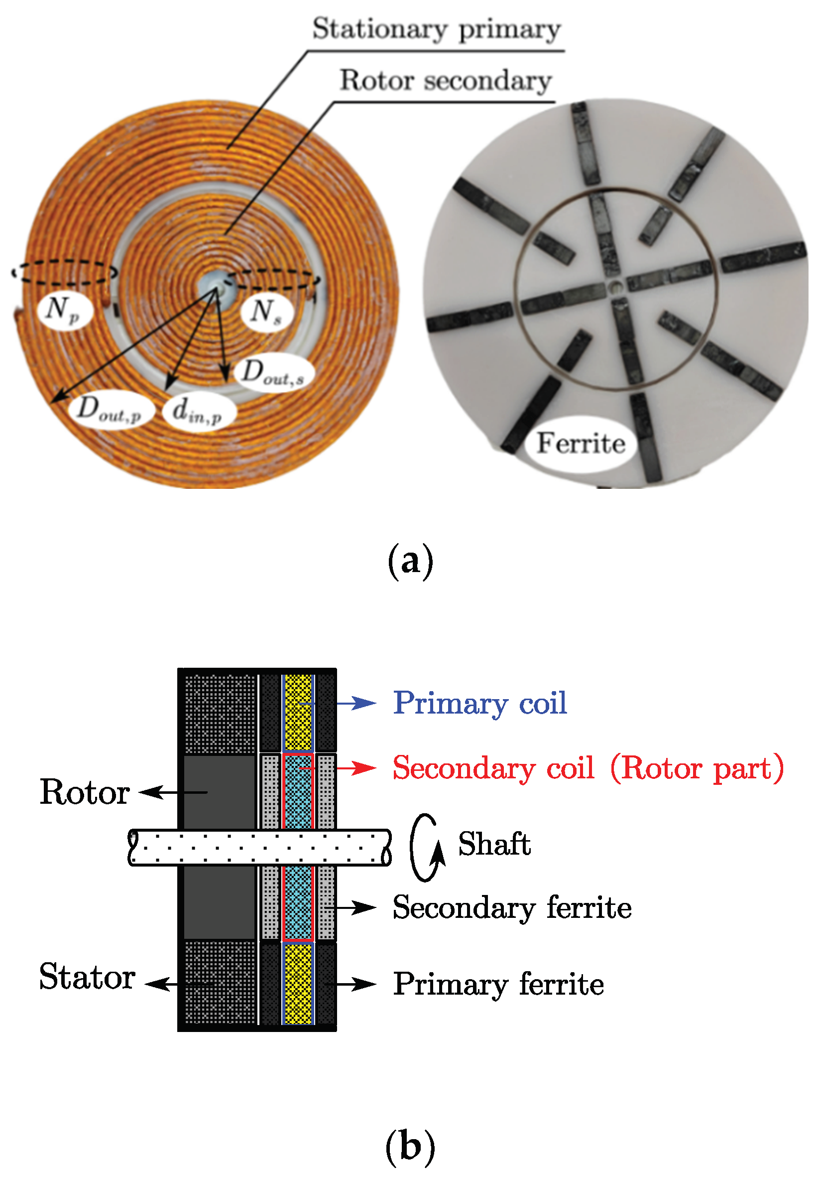
3.1. System Design
To verify above theoretical analysis, a 100-W laboratory level experimental setup and a practical three-axis robotic arm are designed. The IPT-based wireless slipring prototype is shown in Figure 6. Here, the 0.025 × 2500 stranded Litz wire for both primary and secondary coils and the FERROXCUBE 3F46 ferrite shielding are utilized. It should be pointed out that the sandwiched structure is adopted for the coupler and the coils are laid out on the middle layer. To achieve a high coil quality factor, we have chosen the operating frequency to be around 800 kHz. Silicon Carbide (SiC) MOSFETs C2M0080120D are applied to implement the input full-bridge inverter. Additionally, SiC diodes IDW30G65C are adopted at the full-wave rectifier. The dimension of the magnetic coupling structure and the designed system parameters are detailed in Table 1.
Figure 6.
The prototype of the proposed wireless slipring. (a) vertical view and (b) left view.
Table 1.
System Parameters.
Substituting system parameters shown in Table 1 into Equations (6) and (8), the compensation capacitors, and , are calculated, which are 2.09 nF and 10.98 nF, respectively.
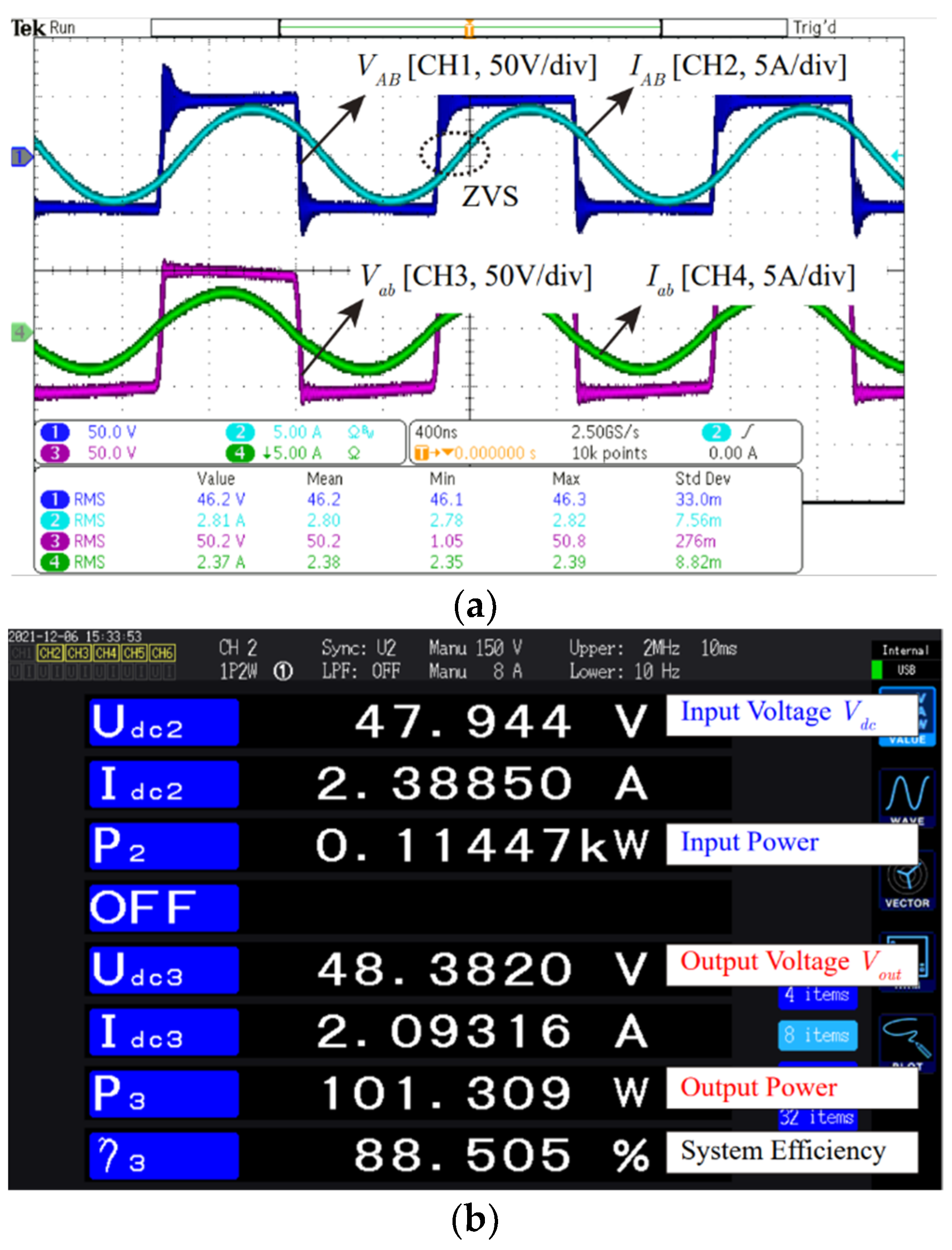
3.2. Experimental Results
Figure 7 represents the measured , , and by HIOKI IM3536 LCR meter. Obviously, the system has good self-inductances and coupling factor stability under the rotating condition. According to Equations (7) and (8), it will ensure that the system has approximate constant output voltage.
Figure 7.
The measured , , and of the IPT coupler.
Figure 8 shows the measured waveforms of the IPT-based slipring system when the output power is 100 W (rated output power). The input voltage, , always slightly lags behind the input current , which means that ZVS operation is achieved for the MOSFET-based inverter and verifies the correctness of Equation (10).
Figure 8.
Experimental waveforms of the input voltage , input current , output voltage , and output current when the system operates at the rated power.
A HIOKI PW6001 power analyzer is applied to measure the efficiency from DC power source to load, which is defined as , and the output DC voltage , which are shown in Figure 9 and Figure 10. As shown in Figure 9, the maximum efficiency of 90.3% is obtained at the rated power condition. Additionally, the constant output voltage of 48 V is approximately achieved at different load conditions, which is also demonstrated by Figure 11. Figure 9, Figure 10 and Figure 11 verify the correctness of Equations (7) and (8).
Figure 9.
Measured efficiency from DC power source to load by power analyzer.
Figure 10.
Measured efficiency and output voltage of the IPT system.
Figure 11.
Dynamic behavior of the IPT-based slipring with different output powers.
In addition, to verify the dynamic characteristics of the proposed IPT-based slipring system, a two-axis robot manipulator is designed, as shown in Figure 12a. The simplified diagram of the test setup design is presented in Figure 12b. Two identical wireless sliprings shown in Figure 6 are mounted on the same shaft and their rotor windings (red part) are connected together. According to Equations (6) and (7) and Table 1, the compensation capacitors , , and shown in Figure 12b are 2.09 nF, 5.49 nF, and 2.09 nF, respectively. In such a design, the measured , , , and are shown in Figure 13a at 1000 RPM (revolutions per minute) of the rotor part. The constant output voltage of 48 V is approximately achieved in the presence of rotor speeds, as shown in Figure 13b. From Figure 13b, additionally, the system efficiency, with respect to the output power of 100 W, is up to 88.5%.
Figure 12.
(a) Two-axis robot arm and (b) its circuit model.
Figure 13.
(a) Experimental waveforms of , , , and , and (b) the system efficiency of the two-axis robot arm.
The proposed IPT-based wireless slipring is applied to a three-axis robot manipulator, as shown in Figure 14. It operates stably without the limitation of the rotation angle and speed and has been applied in industry.
Figure 14.
(a) 3D structure and (b) experimental prototype of the three-axis robot manipulator.
4. Conclusions
This paper proposed a coaxial and coplanar IPT-based wireless slipring for multi-axis robot arms. The minimum axial length in mechanical structure is the outstanding advantage compared with conventional solutions. Its 3D FEM model is presented, and the output voltage characteristic is analyzed. A 100-W laboratory level experimental prototype and a practical three-axis robot manipulator are implemented. The experimental results show that the constant output voltage of 48 V is achieved in the presence of arbitrary electrical motor speeds and load conditions. The maximum efficiency from the DC power source to load is up to 90.3%.
Author Contributions
Investigation, C.S.; Methodology, L.C.; Project administration, J.L. All authors have read and agreed to the published version of the manuscript.
Funding
This research received no external funding.
Conflicts of Interest
The authors declare no conflict of interest.
References
- Brown, L.; Kuhlmann-Wilsdorf, D.; Jesser, W. Testing and Evaluation of Metal Fiber Brush Operation on Slip Rings and Commutators. IEEE Trans. Compon. Packag. Technol. 2008, 31, 485–494. [Google Scholar] [CrossRef]
- Patil, D.; McDonough, M.K.; Miller, J.M.; Fahimi, B.; Balsara, P.T. Wireless Power Transfer for Vehicular Applications: Overview and Challenges. IEEE Trans. Transp. Electrif. 2018, 4, 3–37. [Google Scholar] [CrossRef]
- Dai, J.; Ludois, D.C. A Survey of Wireless Power Transfer and a Critical Comparison of Inductive and Capacitive Coupling for Small Gap Applications. IEEE Trans. Power Electron. 2015, 30, 6017–6029. [Google Scholar] [CrossRef]
- Hui, S.Y.R.; Zhong, W.; Lee, C.K. A Critical Review of Recent Progress in Mid-Range Wireless Power Transfer. IEEE Trans. Power Electron. 2014, 29, 4500–4511. [Google Scholar] [CrossRef] [Green Version]
- Jayalath, S.; Khan, A. Design, Challenges, and Trends of Inductive Power Transfer Couplers for Electric Vehicles: A Review. IEEE J. Emerg. Sel. Top. Power Electron. 2021, 9, 6196–6218. [Google Scholar] [CrossRef]
- Hagen, S.; Tisler, M.; Dai, J.; Brown, I.P.; Ludois, D.C. Use of the Rotating Rectifier Board as a Capacitive Power Coupler for Brushless Wound Field Synchronous Machines. IEEE J. Emerg. Sel. Top. Power Electron. 2022, 10, 170–183. [Google Scholar] [CrossRef]
- Wu, X.; Su, Y.; Hu, A.P.; Qing, X.; Hou, X. Multiobjective Parameter Optimization of a Four-Plate Capacitive Power Transfer System. IEEE J. Emerg. Sel. Top. Power Electron. 2021, 9, 2328–2342. [Google Scholar] [CrossRef]
- Lee, J.-Y.; Huang, L.; Chen, C. Design and implementation of contactless maglev rotating power transfer system with new rotary inductive coupled structure. In Proceedings of the 2016 IEEE 8th International Power Electronics and Motion Control Conference (IPEMC-ECCE Asia), Hefei, China, 22–26 May 2016; pp. 2442–2449. [Google Scholar]
- Abou Houran, M.; Li, X.; Yang, X.; Chen, W.; Hassan, A.; Samizadeh, M.; Karami, B. Design of Coaxial WPT Coils for Linear and Rotational Movement-Based Applications. In Proceedings of the 2020 IEEE 9th International Power Electronics and Motion Control Conference (IPEMC2020-ECCE Asia), Nanjing, China, 29 November–2 December 2020; pp. 3288–3292. [Google Scholar]
- He, G.; Chen, Q.; Ren, X.; Wong, S.; Zhang, Z. Modeling and Design of Contactless Sliprings for Rotary Applications. IEEE Trans. Ind. Electron. 2019, 66, 4130–4140. [Google Scholar] [CrossRef]
- Robertson, D.; Bhargava, K.; Mishriki, F.; Ren, S.S.; Walton, R.; Lecias, E.S. Contactless Power Transfer System. U.S. Patent No. 9,646,763, 9 May 2017. [Google Scholar]
- Zhang, Y.; Yang, J.; Jiang, D.; Li, D.; Qu, R. Design, manufacture, and Test of a Rotary Transformer for Contactless Power Transfer System. IEEE Trans. Magn. 2021, 58, 8400206. [Google Scholar] [CrossRef]
- Abdolkhani, A.; Hu, A.P. Face to Face Through-hole Contactless Slipring System for Rotary Applications. Int. J. Adv. Res. Electr. Electron. Instrum. Eng. 2013, 2, 4277–4286. [Google Scholar]
- Abdolkhani, A.; Hu, A.P. Improved Coupling Design of Contactless Slipring for Rotary Applications. IEEE J. Emerg. Sel. Top. Power Electron. 2015, 3, 288–295. [Google Scholar] [CrossRef]
- Song, K.; Ma, B.; Yang, G.; Jiang, J.; Wei, R.; Zhang, H.; Zhu, C. A Rotation-Lightweight Wireless Power Transfer System for Solar Wing Driving. IEEE Trans. Power Electron. 2019, 34, 8816–8830. [Google Scholar] [CrossRef]
- Abdolkhani, A.; Hu, A.P.; Nair, N.C. A Double Stator Through-hole Type Contactless Slipring for Rotary Wireless Power Transfer Applications. IEEE Trans. Energy Convers. 2014, 29, 426–434. [Google Scholar]
- Raminosoa, T.; Wiles, R.H.; Wilkins, J. Novel Rotary Transformer Topology With Improved Power Transfer Capability for High-Speed Applications. IEEE Trans. Ind. Appl. 2020, 56, 277–286. [Google Scholar] [CrossRef]
Publisher’s Note: MDPI stays neutral with regard to jurisdictional claims in published maps and institutional affiliations. |
© 2022 by the authors. Licensee MDPI, Basel, Switzerland. This article is an open access article distributed under the terms and conditions of the Creative Commons Attribution (CC BY) license (https://creativecommons.org/licenses/by/4.0/).