Article

SSOR Preconditioned Gauss-Seidel Detection and Its Hardware Architecture for 5G and beyond Massive MIMO Networks

1
Computer Science Department, Fitchburg State University, Fitchburg, MA 01420, USA
2
Department of Computer Science and Engineering, University of North Texas, Denton, TX 76203, USA
*
Author to whom correspondence should be addressed.
These authors contributed equally to this work.
Electronics 2021, 10(5), 578; https://doi.org/10.3390/electronics10050578
Submission received: 2 January 2021 / Revised: 23 February 2021 / Accepted: 24 February 2021 / Published: 1 March 2021
(This article belongs to the Special Issue MIMO for Next Generation Wireless Systems)

Abstract

:
With the limitedness of the sub-6 GHz bandwidth, the world is exploring a thrilling wireless technology known as massive MIMO. This wireless access technology is swiftly becoming key for 5G, B5G, and 6G network deployment. The massive MIMO system brings together antennas at both base stations and the user terminals to provide high spectral service. Despite the fact that massive MIMO offers astronomical benefits such as low latency, high data rate, improved array gain, and far better reliability, it faces several implementation challenges due to the hundreds of antennas at the base station. The signal detection at the base station during the uplink is one of the critical issues in this technology. Detection of user signal becomes computationally complex with a multitude of antennas present in the massive MIMO systems. This paper proposes a novel preconditioned and accelerated Gauss–Siedel algorithm referred to as Symmetric Successive Over-relaxation Preconditioned Gauss-Seidel (SSORGS). The proposed algorithm will address the signal detection challenges associated with massive MIMO technology. Furthermore, we enhance the convergence rate of the proposed algorithm by introducing a novel Symmetric Successive Over-relaxation preconditioner (SSOR) scheme and an initialization scheme based on the instantaneous channel condition between the base station and the user. The simulation results show that the proposed algorithm referred to as Symmetric Successive Over-relaxation Preconditioned Gauss-Seidel (SSORGS) provides optimal BER performance. At BER = 10 3 , over the range of SNR, the SSORGS algorithm performs better than the traditional algorithms. Additionally, the proposed algorithm is computationally more efficient than the traditional algorithms. Furthermore, we designed a comprehensive hardware architecture for the SSORGS algorithm to find the interrelated components necessary to build the actual physical system.

1. Introduction

With globalization, wireless data traffic has seen a tremendous surge over the past two decades. To cope up with this colossal increment in wireless data traffic, the cellular base station is deployed within a few hundred-meter distance. Along with cellular broadband, state-of-the-art technologies such as the Internet of Things (IoT), smart cities, mobile cloud, smart vehicular communication, Augmented Reality (AR), Virtual Reality (VR), and Mixed Reality (MR) are also adding to the increasing data traffic. A complete wirelessly joined globe is anticipated in the next few decades, predominantly depicted by the colossal increase in users, increased wireless data traffic, connectivity, and a great collection of wireless applications. Recent research has shown that by the end of 2024, the total traffic per month will be higher than 130 billion gigabytes. The 5G, beyond 5G (B5G), and 6G networks will be carrying the majority of this load [1].
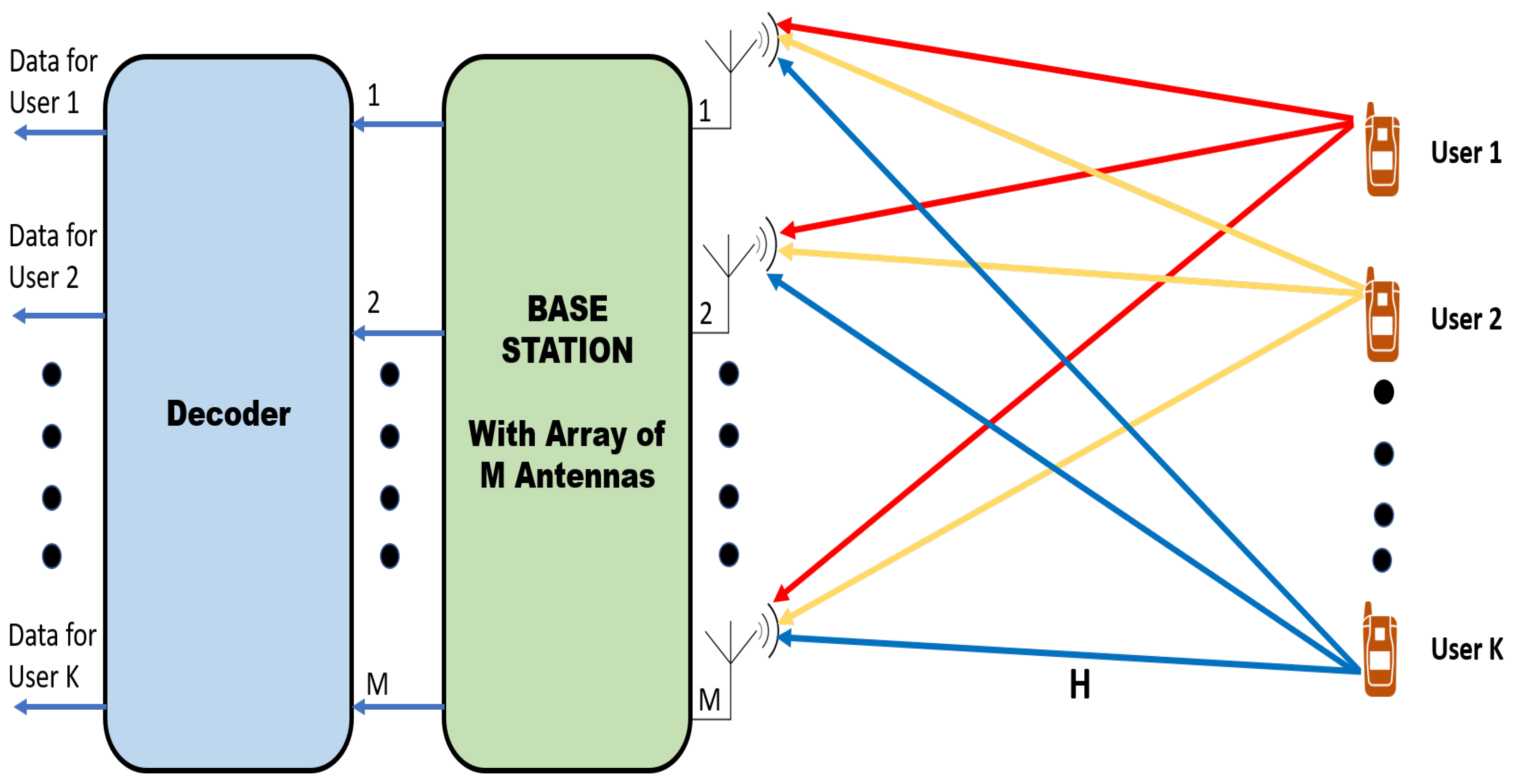
The 5G, B5G, and 6G networks are envisioned to address these globally rising demands in wireless information traffic. With the development of massive MIMO, an intriguing wireless access technology, there are some promises to supply the needs of these indispensable demands. Massive MIMO is contemplated as the breakthrough technology for the future generation 5G, B5G, and 6G networks. Massive MIMO technology is an upgraded version of prevalent MIMO technology. Currently, MIMO technology is an essential element on HSPA+ (3G), WiMAX, 4G Long Term Evolution (4G LTE), IEEE 802.11n (Wi-Fi), and IEEE 802.11ac (Wi-Fi) technology. Massive MIMO, to serve the tens of users, uses hundreds of base station antennas simultaneously [2,3,4,5]. The pivotal benefit of the massive MIMO is the array gain that it attains due to the thousands of the base station antenna [5]. The hundreds of antenna elements at the base station assists in focusing energy on a confined region which helps this technology to achieve benefits such as high spectral efficiency and increased data rate. During the downlink, the 3D beams radiated from the base station becomes more narrower and directed towards the intended user. These narrow beams reduce the interference to the neighboring users and improve the throughput for the intended user [6]. A massive MIMO downlink and uplink system are shown in Figure 1. Apart from high energy and spectral efficiency, massive MIMO also provides superior data rate, low power consumption, ultra-low latency, robustness to interference and jamming, strengthened security [7].

1.1. Relevant Prior Art and Motivation

Despite the fact that massive MIMO provides tremendous advantages for future generation networks, it faces numerous implementation challenges created by the multitude of base station antenna elements. Uplink signal detection is one of the underlying issues in massive MIMO deployment. With a large number of antennas, there arises an issue of computational complexity and poor error performance. Apart from that, all the user signals transmitted by tens and hundreds of users simultaneously at the base station superimposes thereby creating unwanted interference. This adds more complexity in separating user signals transmitted by different users.
Various algorithms have been proposed to discover an optimal detector by both academia and industry research for massive MIMO uplink signal detection. Still, a need for a near-optimal solution is imminent. The near-optimal solution should be designed to boost the error performance with acceptable computational complexity. Several linear and non-linear detectors have been proposed. The linear detectors such as Maximum Likelihood (ML), Zero Forcing (ZF), and  Minimum Mean Square Error (MMSE) have been considered for massive MIMO signal detection [8,9,10]. ML detection provides optimal performance, but it is computationally infeasible for a system such as massive MIMO involving thousands of antennas. The ZF method provides the mitigation of the inter-antenna interference. However, for a channel with ill-conditioned matrices, more noise is added, which reduces the optimal performance [11]. Compared to the ZF detector, the  MMSE detector provides superior error performance. This is because MMSE takes noise power into account during the signal detection at the base station [12]. All the linear detection methods include intricate matrix inversion, and for a system with hundreds of antenna terminals such as massive MIMO, computational complexity increases dramatically. The algorithm presented in [13] combines the ZF and MMSE algorithm with the Successive Interference Cancellation (SIC) method. The combined algorithms were called ZF-SIC and MMSE-SIC and were designed to reduce the interference from formerly detected symbols. However, the performance was far from near-optimal in the combined algorithms. Apart from these linear detectors, several non-linear detectors were also considered for a massive MIMO system. The non-linear detectors such as Sphere Decoder (SD) provide the appropriate error performance. Another non-linear detector known as SIC provides acceptable error performance. However, for these non-linear detectors, computational complexity was still the biggest issue for a system with a greater number of antennas, making them inefficient to be used in massive MIMO systems [14,15]. Several iterative methods were also taken into consideration for a massive MIMO system. Neumann Series Approximation (NSA) [16], Approximate Message Passing (AMP) [17], Jacobi method [18], and Richardson method [19] were presented, but the complexity was reduced moderately when compared to the traditional linear and non-linear methods. The popular iterative methods such as Gauss–Seidel (GS) [20], Least-square regression selection [21], Jacobi [22], and Conjugate Gradient (CG) [23] were taken into account for massive MIMO detection. Still, the near-optimal result was far from acceptable. Several other methods such as Huber fitting-based ADMM (Alternating Direction Method of Multipliers) and conventional ADMM method [24] were also considered recently for uplink signal detection, but for a system with a large number of antennas, these algorithms do not provide a good trade-off between the error and the complexity. Recently, various optimal algorithm are designed for the uplink signal detection [25,26,27,28,29,30].
In this paper, we present a novel preconditioned and accelerated Gauss-Siedel method to address the concerns in massive MIMO uplink signal detection. The convergence of the proposed algorithm is enhanced by introducing a novel Symmetric Successive Over-relaxation preconditioner (SSOR) scheme and an initialization scheme based on the instantaneous channel condition between the base station and the user. The proposed algorithm is referred to as Symmetric Successive Over-relaxation Preconditioned Gauss–Seidel (SSORGS). The results from the matlab simulation show that the proposed SSORGS algorithm provides an optional BER performance. Apart front the BER performance, the proposed SSORGS algorithm has achievable computational complexity. Additionally, a comprehensive hardware architecture is designed for the the proposed SSORGS algorithm. This hardware design will find the interrelated components necessary to build the actual physical system.

1.2. Contributions

The key contributions of this work are summarized as follows:
  • We study the uplink signal detection issue in the massive MIMO system. We propose an efficient iterative algorithm and its hardware architecture referred to as SSORGS to address the signal detection problem in the massive MIMO systems.
  • We analyze the error performance and time complexity of the proposed SSORGS algorithm. We compare the performance of the SSORGS algorithm with the conventional algorithms such as CG, GS, ZF, MMSE, and ML.
  • The results from the matlab simulation show that the proposed SSORGS algorithm outperforms the traditional iterative algorithms. The algorithm achieves near-optimal BER performance with acceptable computational complexity.

1.3. Paper Outline

The remainder of the paper is structured as follows: Section 2 lays out the system model adapted for conducting the simulations. Additionally, Section 2 also presents the proposed SSORGS algorithm. The simulation setup and numerical results are presented in Section 3. Furthermore, the analysis of the simulation is discussed in Section 3. Section 4 describes the designed hardware architecture. Additionally, in Section 4, we compute the computational complexity of the proposed SSORGS algorithm and compare the complexity with the traditional MIMO detection algorithms. The Section 5 summarizes this work by outlining the key ideas and the future work.

1.4. Notations

In this paper, the lower-case letters denote column vectors, and upper-case letters denote matrices. The inverse and transpose of the matrix are represented by ( . ) 1 and ( . ) respectively. The hermitian transpose is represented by ( . ) H . The  CN ( 0 , V ) denote the circular symmetric complex Gaussian distribution with zero mean and co-variance V, and  C M denote the space of M-element complex vectors. I M denotes the M × M identity matrix.

2. System Model and Proposed Algorithm

2.1. System Model

We took into account M antennas equipped at the base station in a massive MIMO uplink system in a single cell system as shown in Figure 2. These M antennas are continuously communicating with N (M ≫ N) single-antenna users at the same time. The data from the user terminal is transmitted via the uplink channel, including the pilot signal. The uplink signal transmission in a massive MIMO system is shown in Figure 3.
The most commonly used Rayleigh fading channel model is considered between the BS and the user terminals. Rayleigh fading channel is accurate model to represent the channel with multi-path propagation. This model assumes that the magnitude of a signal that has passed through communication channel will fade randomly, according to a Rayleigh distribution, and it is seen as the most appropriate model for modeling wireless signal propagation. For  σ > 0 , and  y > 0 , the Rayleigh distribution is a continuous distribution with the probability density function:
f ( y ; σ ) = y σ 2 exp y 2 2 σ 2
To reduce the effect of Inter-Symbol Interference, we assumed a long cyclic prefix and each users bit streams are represented into a constellation point [21,24]. The user signal received at the base station:
y = H x + n u p l i n k
where x C N is the signal or pilot signal transmitted by the user, H is the channel matrix, and y C M is the signal received at the base station. Each element of vector H C M × N have unit variance and zero mean. In addition, each element is i.i.d (independent and identically distributed), i.e., H CN ( 0 , 1 ) . The  n u p l i n k C M is the noise at the receiver with added interference, where n u p l i n k = n u p l i n k i n t e r f e r e n c e + n n o i s e . The interference added in the noise is variable as it may get affected by the channel vector H. The user signal x estimated by the linear detector MMSE is:
x = ( H H H + N 0 E s I ) 1 H H y
where N 0 E s is the ratio of the signal power and noise power. Equation (3) can be represented as:
x = A 1 B
where A = ( H H H + N 0 E s I ) and B = H H y . We can reinterpret Equation (4) as the linear equation to avoid the computationally complex matrix inversions. The overall complexity of the algorithm is considerably reduced if we can eliminate the complex matrix inversion in the algorithm. The linear equation representation of Equation (4) is given as:
B = A x
To apply the preconditioner in the above uplink system, we need to make matrix A sparse. Making the matrix sparse will speed up data processing and save a significant amount of memory. Additionally, the sparse matrix does not perform unnecessary low-level arithmetic; thus, they improve the execution time.
A ^ = s p a r s e ( A )
Using Equation (6) in Equation (5):
B = A ^ x
Now, Lets consider splitting of matrix A on to upper, lower, and diagonal matrix as:
A ^ = D U L
where D represents a diagonal matrix, U represents an upper triangular matrix, and  L represents a lower triangular matrix. Then, the Equation (8) can be solved using conventional GS method as:
x i + 1 = ( D U ) 1 ( B + L x i )
where the approximated user signal during the i t h iteration is x i . If the matrix H is a Hermitian positive definite matrix, then for any initial value of x, the Equation (9) converges. The initial value of x is denoted by x 0 . To make Equation (9) converge faster, preconditioning is applied before the iteration. Preconditioning transforms the system into a simple equivalent mathematical form, which can be solved using an iterative method. We applied SSOR preconditioning to accelerate the convergence of the proposed algorithm. To improve the convergence, an identical preconditioned system for (4) can be created to apply the preconditioner. The identical system is presented as:
P 1 Y = P 1 A ^ x   ( w h e r e   P A ^ )
where the preconditioner matrix P is positive definite and symmetric. The preconditioner will estimate A ^ 1 as | | I P 1 A ^ | | < 1 [31]. In this work, SSOR preconditioner is applied to precondition our initial system. The SSOR preconditioner is given as:
M S S O R = 1 r ( 2 r ) ( D r L ) D 1 ( D r U )
where r is the relaxation parameter. In massive MIMO systems this relaxation parameter can be approximated by Equation (12) [32]:
r = 2 1 + 2 1 1 + N M 2 1
Here the relaxation parameter only depends on the number of base station antennas (M) and the number of users (N) of the massive MIMO system. The convergence of this optimal relaxation parameter is presented in [32]. Since the relaxation parameter depends only upon the number of base station antennas and the number of users, the relaxation parameter value is constant once the massive MIMO configuration has been fixed. Thus, we do not have to compute the relaxation parameter M S S O R even if the channel conditions change with time. Since the relaxation parameter is only computed once for each configuration, we avoid its computation during each algorithm iteration, making it computationally efficient.
For additional acceleration and convergence, we introduced an initialization scheme to instantiate the user signal x. Usually, a zero vector is used as an initial solution x 0 in conventional iterative methods such as the GS method. The initial solution with a zero vector is far from the final solution. Thus, it requires more number of iterations to reach the final solution. The number of increased iteration increases computational complexity and decreases the convergence rate. Due to the large number of antennas in the massive MIMO systems, each iteration has a very high computational cost. Thus, finding the optimal solution with fewer iterations is crucial for implementing massive MIMO for 5G, B5G, and 6G networks. The proposed initial solution is simple, and it only depends on the received signal and the matrices computed during preconditioning. The estimated initial solution is approximated as:
x 0 = ( D L U ) 1 B
The diagonal, upper, and lower triangular matrix values were already determined during the computation of the preconditioner. Thus, the proposed initial solution does not add extra complexity to the system. Also, this factor is computed only once outside of the algorithm iteration to reduce complexity.

2.2. Proposed Algorithm

This section summarizes the proposed SSORGS algorithm. The step-wise summary of proposed SSORGS algorithm is presented in Algorithm 1. The accelerator and preconditioner applied in the method improve the convergence rate. The faster convergence of an algorithm reduces the number of iteration required to reach the final solution. The low number of iteration reduces the complexity of the algorithm noticeably. Besides, the hardware architecture designed for the SSORGS algorithm identifies the necessary elements and the relationships between those components. The primary inputs given to the system are y, H, N 0 , E s , N, and M, where y is the composite signal at the base station, N 0 is the complex noise variance per receive antenna (noise power), E s is the average symbol energy (signal power), and N is the number of users simultaneously communicating with the base station, M is the number of antennas at the base station, and H is the channel matrix. All the matrix-vector multiplication is done during the preprocessing. Since preprocessing is done outside of the iteration loop, doing complex calculations outside of the loop reduces the complexity of the algorithm. A = ( H H H + N 0 E s I ) is the gramian matrix, where N 0 is noise power and E s is the signal power. To boost the rate of convergence of the proposed algorithm, SSOR preconditioning is applied to the matrix A. This preconditioning is done in advance of computing the diagonal matrix, lower triangular matrix, and an upper triangular matrix. We need these upper triangular, lower triangular, and diagonal matrix during the user signal x-update. We also designed a novel initialization matrix x 0 presented in Equation (13). This initializer will further enhance the convergence rate for the proposed SSORGS algorithm. This Equation (13) is used the initialize the user signal x i . The GS method is presented in Equation (9). This equation is used during algorithm iteration to estimate the user signal x i . The advantage of using the proposed method is the simplicity. We do not have to compute any complex matrix operation or matrix inversion at any point during the user signal estimation. This feature makes this algorithm way less complicated compared to the conventional iterative, linear, and non-linear algorithms used for signal detection in massive MIMO. The complete details of all the computations performed in Algorithm 1 are presented in Section 2.1.
Algorithm 1 SSORGS Algorithm Proposed for Massive MIMO Uplink Singal Detection
Inputs: y , H , N 0 , E s , N , M
Pre-processing:
  •     A = N 0 E s I + ( ( H H ) H )
  •     B = ( H H ) y
  •     A ^ = s p a r s e ( A )
  •     C o m p u t e :
        U = u p p e r ( A ^ )
        D = d i a g o n a l ( A ^ )
        L = l o w e r ( A ^ )
  •     r = 2 1 + 2 1 1 + N M 2 1
  •     M S S O R = 1 r ( 2 r ) ( D r L ) D 1 ( D r U )
  •     A ˜ = ( M S S O R ) 1 A ^
  •     B ˜ = ( M S S O R ) 1 B
  •     C o m p u t e :
        U ˜ = u p p e r ( A ˜ )
        D ˜ = d i a g o n a l ( A ˜ )
        L ˜ = l o w e r ( A ˜ )
  •     x 0 = ( D ˜ L ˜ U ˜ ) 1 B ˜
  •       for i = 1 t o i m a x do
  •           x i + 1 = [ ( D ˜ U ˜ ) 1 ( L ˜ x i + B ˜ ) ]
  •       End for
Output: x i

3. Simulation Setup and Simulation Results

3.1. Simulation Setup

This section presents the simulation setup used to evaluate the performance of the proposed SSORGS algorithm. To assess the performance of the proposed algorithm, we compare it with traditional massive MIMO uplink detection algorithms. A massive MIMO system is considered with 16 to 512 BS antenna terminals. These base station antenna terminals are concurrently communicating with single-antenna users. We assumed that 16 users are communicating with the base station at a time. The bandwidth is considered to be 20 MHz. We considered the Rayleigh Fading channel model between the user terminals and the base station. Rayleigh fading channel is a standard statistical model to represent the channel with multi-path propagation. This model is seen as the most appropriate model for modeling wireless signal propagation [33,34]. Different modulation schemes are used during the simulation. The modulation schemes used during the simulations are 64-QAM (Quadrature Amplitude Modulation), 16-QAM, QPSK (Quadrature Phase Shift Keying), and Binary Phase Shift Keying (BPSK). The simulations were executed in Matlab under Windows OS, with a 1.5 GHz Intel Core i5 processor and 8GB of RAM. All the simulation parameters are shown in Table 1.

3.2. Simulation Results

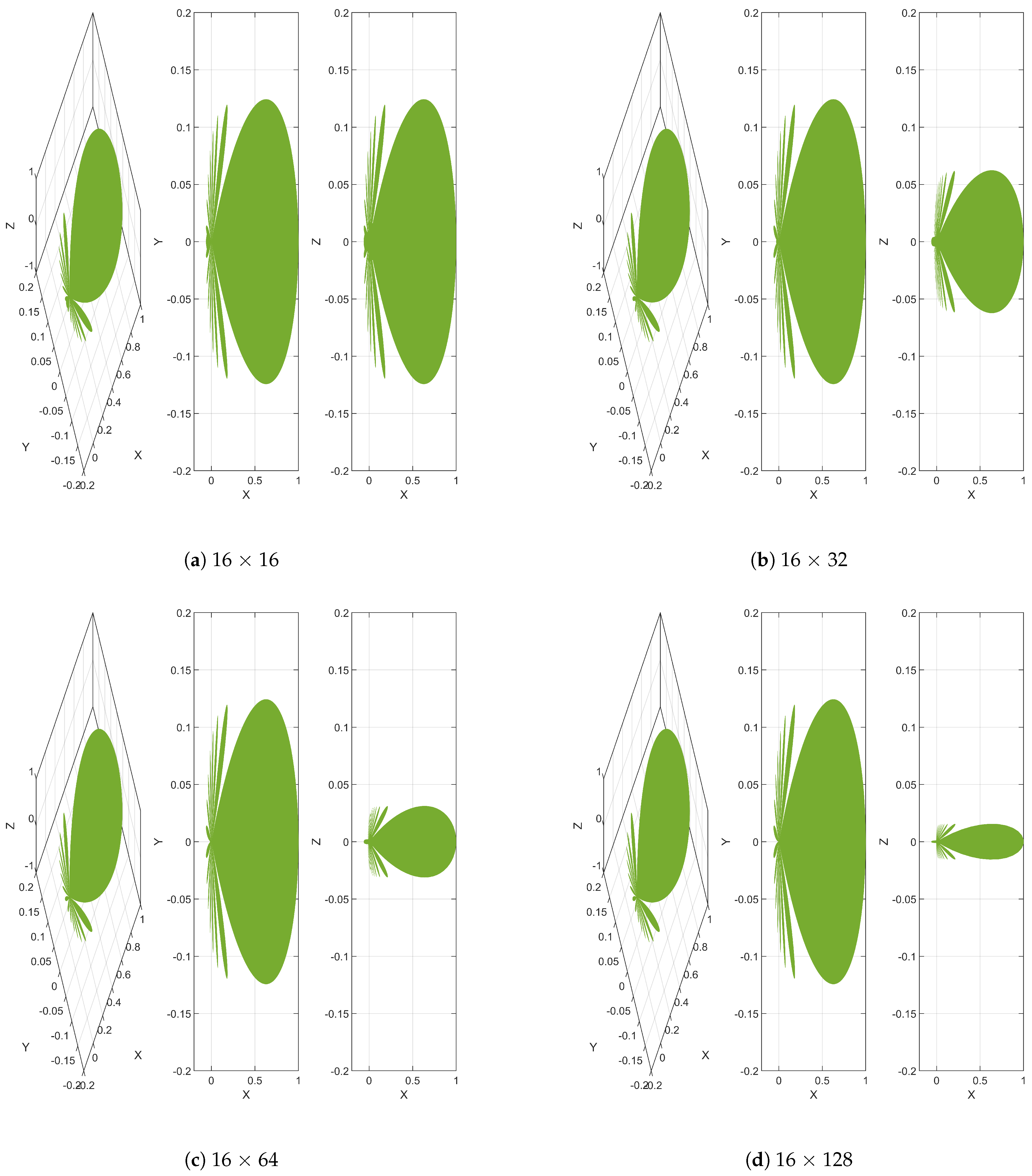
This section presents the overall simulation results and analysis of the performance of the proposed SSORGS algorithm. Figure 4 shows the antenna beam pattern with different antenna configurations that we used in our simulations. We can see that with the increase in the number of antennas, antenna directivity increases. With a 16 base station antenna configuration as shown in Figure 4a, the signal will spread in a wider direction. Thus, the users at the edge of the cell will receive lower signal strength, whereas unintended users near the antenna will receive higher signal strength. For the unintended users, this higher signal strength actually becomes interference as the signal is not intended for them. If we increase the number of the base station antenna to 32, the beams become narrower. These narrow beams are spatially focused toward the user. Still, with the 32 antenna configuration as shown in Figure 4b, we will have substantial side lobes near the antenna, which will cause interference to the unintended users. With further increase in base station antenna (64 and 128 antenna configuration), the beams became more narrower and focused toward the users.
With 64 and 128 antenna configuration, the users at the edge of the cell are also receiving higher signal strength. In a system with 64 and 128 antennas, we can see that the side lobes are almost diminished; thus, there will be little to no interference to the unintended users.

3.3. BER Performance

The proposed SSORGS algorithm’s error performance was estimated with various antenna configurations and modulation schemes. Then, the performance was compared with conventional iterative MIMO detection algorithms. For any communication system, BER is defined as the “ratio of the number of error bits transmitted to the total number of bits transmitted during a specific time” [35]. The ML algorithm is the optimal algorithm that provides theoretically maximum performance. ML is used as the benchmark for assessing the performance of massive MIMO detection algorithm measurement for every algorithm has to achieve.
Figure 5 shows the BER performance of the proposed SSORGS algorithm changing base station antenna. This experiment was conducted with 16QAM modulation and 16 users. As shown in Figure 5a, with the 16 base station antenna configuration, the proposed SSORGS algorithm’s performance surpass the traditional CG and GS algorithm. The BER performance was closing the optimal value with a higher value of SNR. Figure 5b shows the BER performance of the proposed algorithm with a base station equipped with 32 antennas. The BER performance of the proposed algorithm outperformed the traditional algorithms, and it was found to be near-optimal. With the further increase in base station antenna as shown in Figure 5c,d, the proposed algorithm performed even better, and the performance was closing the optimal ML algorithm. It should also be noted that the BER performance for every algorithm simulated has improved largely with the increasing number of the antenna at the base station. This is due to beamforming that happens due to the array gain provided by thousands of antenna terminals at the base station. With the increase in the number of antennas, antenna directivity increases, which improves the signal received by the intended user and reduces the interference.
We then assessed the proposed SSORGS algorithm’s performance by increasing the number of antennas at the base station. We did this simulation with just 16 single antenna users using 16-QAM modulation. The error performance of the SSORGS algorithm with various antenna configuration is shown in Figure 6. We achieved 4.8 dB gain at BER = 10 3 by growing the base station antenna from 32 to 64. An additional 3.9 dB gain was achieved when the antenna number was increased to 128. Thus, the error performance of the algorithm was improved drastically by increasing the number of antennas at the base station. The higher number of antennas improves the link reliability through spatial diversity and provides more degrees of freedom in the spatial domain. Massive MIMO also makes efficient use of beamforming techniques to improve SNR, latency, and error performance. The beamforming simply allows the base station to adjust the radiation pattern. This adjustment by the base station improves the spectral efficiency of the system as it allows more users to send the information at the same time [7,36].
We then conducted a simulation by applying different modulation schemes. This simulation was conducted with 16 base station antennas and 16 user terminals. For these simulations, we used four different modulation schemes: 64-QAM, 16-QAM, QPSK, and BPSK. We can see the result of the simulation in Figure 7. At BER = 10 3 , a gain of 6 dB was achieved when we changed the modulation scheme from 64QAM to 16QAM. An additional 7 dB gain was achieved when the modulation scheme was changed to QPSK from 16-QAM. Thus, the BER performance for the proposed detection algorithms deteriorates when we increase the modulation order. This is due to the fact that the higher-order modulations have more number of symbols. The more the symbols are close to each other in the constellation diagram, the more likely it is that noise will corrupt the signal. This error can only be avoided by increasing the transmission power. Although the higher modulation order has poor error performance, they provide a higher data rate since more bits are transmitted simultaneously. Thus, for applications where we require a higher data rate and do not care much about error performance, higher modulation order is useful. Thus, modulation order becomes an all-important design factor to consider in massive MIMO systems.

4. Hardware Architecture and Complexity Analysis

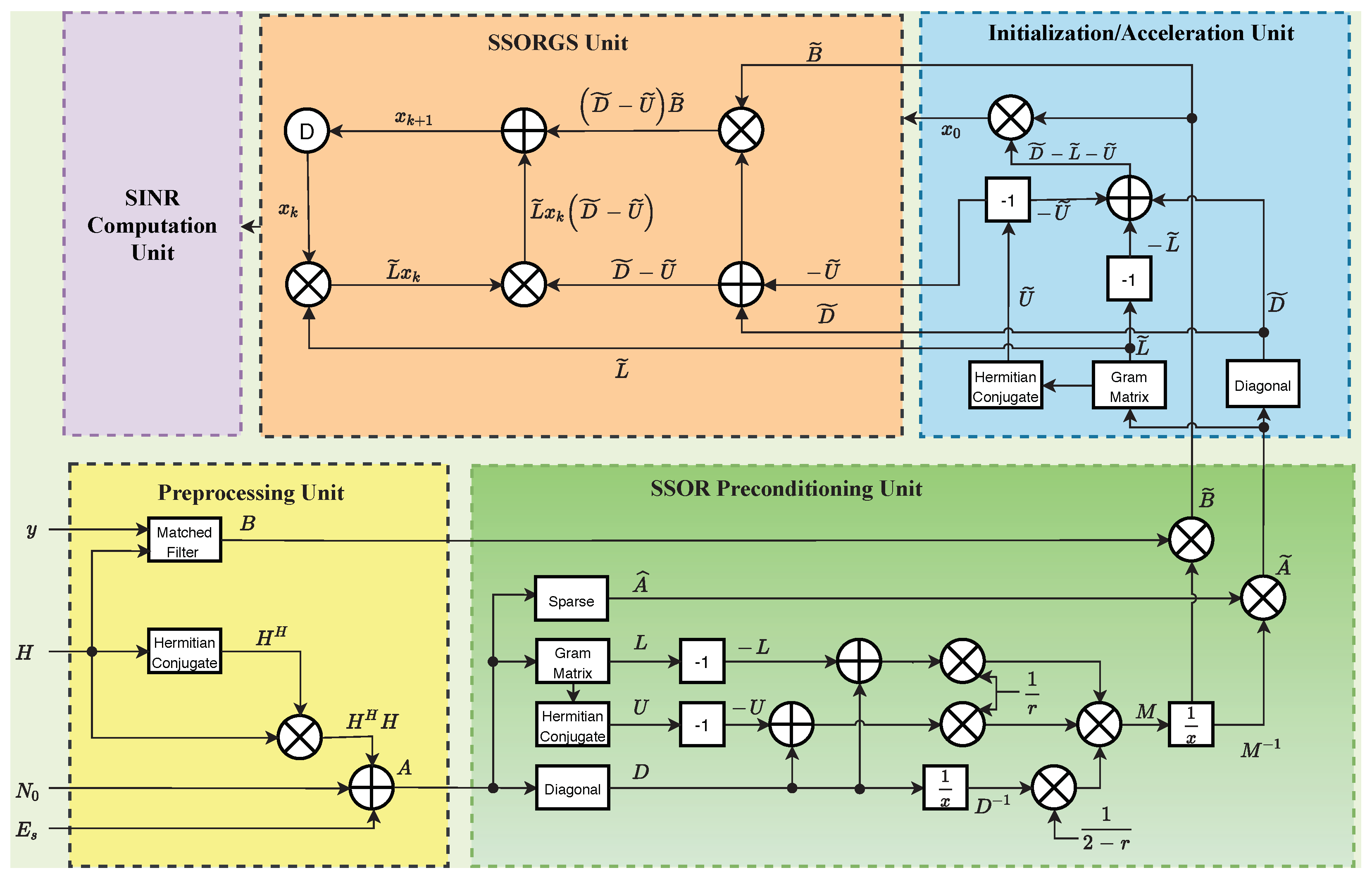
The hardware architecture designed for the SSORGS algorithm is analyzed in this section. We compared the computational complexity of the SSORGS algorithm and the traditional detection algorithms. Figure 8 shows the hardware architecture for the proposed SSORGS massive MIMO detection algorithm. The designed hardware architecture has five different units to do different tasks independently. The five units in the design are the preprocessing unit, initialization/acceleration unit, SSOR preconditioning unit, SSORGS unit, and SINR computation unit. This hardware needs several inputs to function. Some of the major functional inputs to the hardware are channel matrix H, average symbol energy E s , the received signal at the base station y, and noise variance per receive antenna N 0 . The first unit preprocessing unit takes all the inputs and does the preprocessing required before the iteration begins. Most of the complex computations required during the iteration are computed during preprocessing, which reduces the overall complexity of the proposed algorithm. Complex operations such as gram matrix calculation and matrix-vector multiplications are done during the preprocessing. The SSOR preconditioning unit applies the SSOR preconditioner to the gram matrix to improve the algorithm’s convergence. The upper triangular, lower triangular, and diagonal matrices are computed in this unit, required during the x-update of the proposed SSORGS algorithm. The initialization/acceleration unit further improves the algorithm’s convergence by applying the proposed novel initialization scheme. The user signal that will be estimated by the algorithm is initialized with the initial solution generated by this unit. This initial solution uses the diagonal, upper, and lower triangular matrix. The diagonal, upper, and lower triangular matrices were already determined in the preconditioning unit. Thus, the proposed initial solution does not add extra complexity to the algorithm. Finally, the user signal is estimated at the SSORGS method unit. This is the unit that detects all the different signals sent by the users. Then we have the SINR computation unit, which simply computes the SNR for every user signal that has been detected.
Since we are dealing with a generous number of antennas in the massive MIMO systems, evaluating the complexity of the system becomes indispensable before it can be used in real-world scenarios. For all the iterative algorithms such as the proposed SSORS algorithm, computational complexity is majorly resting on the number of complex iterations. To assess the performance of the proposed SSORGS algorithm, we computed the worst-case time complexity of the system. The complexity was then compared with the conventional iterative algorithms. The renowned Big O notation was used to evaluate the work’s worst-case scenario. Big O is the most common metric for calculating the time complexity of the iterative algorithms [37,38,39]. The Big O complexity of the SSORGS algorithms was in the order of O ( i N 2 ) . Here i is the number of complex iteration during the user signal estimation. The proposed algorithm converges in a relatively fewer iteration. The proposed algorithm’s computational complexity is almost similar to the conventional iterative algorithms such as GS and CG. The computational complexity of the CG and GS are also in the order of O ( i N 2 ) . The traditional massive MIMO algorithms such as ZF and MMSE have computational complexity in order of O ( M N 2 ) [40]. The number of antennas at the base station is significantly higher than the number of iterations in the proposed algorithm ( M i ).
Thus, the computational complexity of the proposed SSORGS algorithm is much lower when compared to traditional algorithms such as ZF and MMSE. The complexity performance of the traditional massive MIMO uplink signal detection algorithm and the proposed SSORGS algorithm are summarized in Table 2.

5. Conclusions

Massive MIMO technology is an emerging wireless access technology used in 5G, B5G, and6G networks. Given the pressing need for an efficient uplink signal detection method in massive MIMO systems, a limited amount of research has been conducted to find an algorithm that can provide near-optimal performance with acceptable complexity. This paper introduces an efficient uplink signal detection algorithm for detecting user signals at the base station in massive MIMO systems. The proposed algorithm provides an exceptional balance between the system complexity and the BER performance. Thus, the proposed algorithm is an appropriate candidate to be used in a massive MIMO system. The proposed SSORGS algorithm uses a novel initialization scheme and the SSOR preconditioner to accelerate the convergence and improve its performance. The hardware architecture presented in the paper reveals all the interrelated physical elements required to design the system physically. The results from all the simulations demonstrate that the proposed SSORGS algorithm attains optimal error performance and performs way better than the traditional algorithms for massive MIMO systems. At BER = 10 3 , over the range of SNR, the SSORGS algorithm performs better than the traditional algorithms such as Gauss–Seidel and Conjugate Gradient algorithm. At the same BER of = 10 3 , we achieved 8.7 dB by increasing the base station antenna from 32 to 128. The change in modulation order from 64-QAM to QPSK achieved the gain of 13 dB at BER value = 10 3 . The computational complexity of the proposed algorithm is significantly better when compared to conventional detection algorithms. The proposed SSORGS algorithm has remarkably better performance with the larger number of the base station antenna and lower modulation order. The benefits that the proposed algorithm provides makes it a suitable candidate for massive MIMO signal detection. Thus, the algorithm may help us realize the immense applications that 5G, B5G, and 6G networks can provide.
In the future, we are planning to test the design with multi-antenna user terminals and with a higher number of base station antennas. It would be fascinating to see the use of machine learning and deep learning technology for signal detection in massive MIMO systems. There are many hurdles and challenges still on the way for this developing wireless technology. Other than signal detection issues, there are several other challenges such as pilot signal contamination, energy efficiency, and convergence with older infrastructure. These challenges should be studied further to achieve the promising advantages of 5G, 6G, and beyond networks.

Author Contributions

Conceptualization, R.C., R.A., U.K.D. and M.R.; methodology, R.C., R.A., U.K.D. and M.R.; software, R.C., R.A., U.K.D. and M.R.; validation, R.C., R.A., U.K.D. and M.R.; formal analysis, R.C., R.A., U.K.D. and M.R.; investigation, R.C., R.A., U.K.D. and M.R.; resources, R.C., R.A., U.K.D. and M.R.; data curation, R.C., R.A., U.K.D. and M.R.; writing—original draft preparation, R.C., R.A., U.K.D. and M.R.; writing—review and editing, R.C., R.A., U.K.D. and M.R.; visualization, R.C., R.A., U.K.D. and M.R.; supervision, R.C., R.A., U.K.D. and M.R.; project administration, R.C., R.A., U.K.D. and M.R.; funding acquisition, R.C., R.A., U.K.D. and M.R. All authors have read and agreed to the published version of the manuscript.

Funding

This research received no external funding.

Conflicts of Interest

The authors declare no conflict of interest.

Abbreviations

The following abbreviations are used in this manuscript:
MIMOMultiple-input multiple-output
SSORSuccessive Over-relaxation preconditioner
SSORGSSymmetric Successive Over-relaxation Preconditioned Gauss–Seidel
BERBit Error Rate
M2MMachine to machine
ARAugmented Reality
VRVirtual Reality
MRMixed Reality
3GPP3rd Generation Partnership Project
HSPA+High speed packet access
WiMAXWorldwide interoperability for microwave access
LTELong term evolution
ZFZero-Forcing
IoTInternet of things
MLMaximum Likelihood
MMSEMinimum mean square error
SICSuccessive interference cancellation
NSANeumann Series Approximation
GSGauss Seidel
CGConjugate Gradient
ADMMAlternating Direction Method of Multipliers
CSIChannel State Information

References

  1. Mobile Data Traffic Outlook. Ericsson.com. 2019. Available online: https://www.ericsson.com/en/mobility-report/reports/june-2019/mobile-data-traffic-outlook (accessed on 23 October 2019).
  2. Marzetta, T.L. Massive MIMO: An Introduction. Bell Labs Tech. J. 2015, 20, 11–22. [Google Scholar] [CrossRef]
  3. Rusek, F.; Persson, D.; Lau, B.K.; Larsson, E.G.; Marzetta, T.L.; Edfors, O.; Tufvesson, F. Scaling up MIMO: Opportunities and Challenges With Very Large Arrays. IEEE Signal Process. Mag. 2013, 30, 40–60. [Google Scholar] [CrossRef] [Green Version]
  4. Larsson, E.G.; Tufvesson, F.; Edfors, O.; Marzetta, T.L. Massive MIMO for Next Generation Wireless Systems. IEEE Commun. Mag. 2014, 52, 186–195. [Google Scholar] [CrossRef] [Green Version]
  5. Chataut, R.; Akl, R. Optimal pilot reuse factor based on user environments in 5G Massive MIMO. In Proceedings of the 2018 IEEE 8th Annual Computing and Communication Workshop and Conference (CCWC), Las Vegas, NV, USA, 8–10 January 2018; pp. 845–851. [Google Scholar]
  6. Popovski, P.; Stefanović, Č.; Nielsen, J.J.; De Carvalho, E.; Angjelichinoski, M.; Trillingsgaard, K.F.; Bana, A.S. Wireless Access in Ultra-Reliable Low-Latency Communication (URLLC). IEEE Trans. Commun. 2019, 67, 5783–5801. [Google Scholar] [CrossRef] [Green Version]
  7. Chataut, R.; Akl, R. Massive MIMO Systems for 5G and beyond Networks—Overview, Recent Trends, Challenges, and Future Research Direction. Sensors 2020, 20, 2753. [Google Scholar] [CrossRef] [PubMed]
  8. Liang, Y.C.; Pan, G.M.; Bai, Z.D. Asymptotic performance of MMSE receivers for large systems using random matrix theory. IEEE Trans. Inf. Theory 2007, 53, 4173–4190. [Google Scholar] [CrossRef]
  9. Gustafsson, O.; Bertilsson, E.; Klasson, J.; Ingemarsson, C. Approximate Neumann Series or Exact Matrix Inversion for Massive MIMO? In Proceedings of the 2017 IEEE 24th Symposium on Computer Arithmetic (ARITH), London, UK, 24–26 July 2017; pp. 62–63. [Google Scholar]
  10. Ghacham, S.; Benjillali, M.; Guennoun, Z. Low-complexity detection for massive MIMO systems over correlated Rician fading. In Proceedings of the 2017 13th International Wireless Communications and Mobile Computing Conference (IWCMC), Valencia, Spain, 26–30 June 2017; pp. 1677–1682. [Google Scholar]
  11. Torres, P.; Charrua, L.; Gusmao, A. On the Uplink Detection Performance in MU-MIMO Broadband Systems with a Large Number of BS Antennas. In Proceedings of the OFDM 2014—18th International OFDM Workshop 2014 (InOWo’14), Essen, Germany, 27–28 August 2014; pp. 1–8. [Google Scholar]
  12. Gao, X.; Dai, L.; Ma, Y.; Wang, Z. Low-complexity near-optimal signal detection for uplink large-scale MIMO systems. Electron. Lett. 2014, 50, 1326–1328. [Google Scholar] [CrossRef] [Green Version]
  13. Kim, Y.; Seo, J.H.; Kim, H.M.; Kim, S. Soft linear MMSE detection for coded MIMO systems. In Proceedings of the 2013 19th Asia-Pacific Conference on Communications (APCC), Denpasar, Indonesia, 29–31 August 2013; pp. 657–660. [Google Scholar]
  14. Jeon, Y.; Lee, N.; Hong, S.; Heath, R.W. One-Bit Sphere Decoding for Uplink Massive MIMO Systems With One-Bit ADCs. IEEE Trans. Wirel. Commun. 2018, 17, 4509–4521. [Google Scholar] [CrossRef] [Green Version]
  15. Elghariani, A.; Zoltowski, M. Successive interference cancellation for large-scale MIMO OFDM. In Proceedings of the 2015 IEEE International Conference on Electro/Information Technology (EIT), Dekalb, IL, USA, 21–23 May 2015; pp. 657–661. [Google Scholar]
  16. Zhang, C.; Yang, Y.; Zhang, S.; Zhang, Z.; You, X. Residual-based detections and unified architecture for massive MIMO uplink. arXiv 2018, arXiv:1802.05982. [Google Scholar] [CrossRef] [Green Version]
  17. Chataut, R.; Akl, R. Efficient and low complex uplink detection for 5G massive MIMO systems. In Proceedings of the 2018 IEEE 19th Wireless and Microwave Technology Conference (WAMICON), Sand Key, FL, USA, 9–10 April 2018; pp. 1–6. [Google Scholar]
  18. Zhou, J.; Ye, Y.; Hu, J. Biased MMSE Soft-Output Detection Based on the Jacobi Method in Massive MIMO. In Proceedings of the IEEE International Conference on Communiction Problem-Solving, Beijing, China, 5–7 December 2014; pp. 442–445. [Google Scholar]
  19. Kang, B.; Yoon, J.; Park, J. Low-complexity massive MIMO detectors based on Richardson method. ETRI J. 2013, 39, 326–335. [Google Scholar] [CrossRef]
  20. Wu, Z.; Zhang, C.; Xue, Y.; Xu, S.; You, X. Efficient architecture for soft-output massive MIMO detection with Gauss-Seidel method. In Proceedings of the IEEE Circuits and Systems (ISCAS), Montreal, QC, Canada, 22–25 May 2016; pp. 1886–1889. [Google Scholar]
  21. Chataut, R.; Akl, R.; Dey, U.K. Least Square Regressor Selection Based Detection for Uplink 5G Massive MIMO Systems. In Proceedings of the 2019 IEEE 20th Wireless and Microwave Technology Conference (WAMICON), Cocoa Beach, FL, USA, 8–9 April 2019; pp. 1–6. [Google Scholar]
  22. Gao, X.; Dai, L.; Hu, Y.; Wang, Z.; Wang, Z. Matrix Inversion-Less Signal Detection Using SOR Method for Uplink Large-Scale MIMO Systems. In Proceedings of the IEEE Global Communications Conference, Austin, TX, USA, 8–12 December 2014; pp. 3291–3295. [Google Scholar]
  23. Yin, B.; Wu, M.; Cavallaro, J.R.; Studer, C. VLSI design of large-scale soft-output mimo detection using conjugate gradients. In Proceedings of the IEEE Circuits and Systems (ISCAS), Lisbon, Portugal, 24–27 May 2015; pp. 1498–1501. [Google Scholar]
  24. Chataut, R.; Akl, R. Huber Fitting based ADMM Detection for Uplink 5G Massive MIMO Systems. In Proceedings of the 2018 9th IEEE Annual Ubiquitous Computing, Electronics & Mobile Communication Conference (UEMCON), New York, NY, USA, 8–10 November 2018; pp. 33–37. [Google Scholar]
  25. Liu, L.; Peng, G.; Wang, P.; Zhou, S.; Wei, Q.; Yin, S.; Wei, S. Energy- and Area-Efficient Recursive-Conjugate-Gradient-Based MMSE Detector for Massive MIMO Systems. IEEE Trans. Signal Proc. 2020, 68, 573–588. [Google Scholar] [CrossRef]
  26. Ke, M.; Gao, Z.; Wu, Y.; Gao, X.; Schober, R. Compressive Sensing-Based Adaptive Active User Detection and Channel Estimation: Massive Access Meets Massive MIMO. IEEE Trans. Signal Proc. 2020, 68, 764–779. [Google Scholar] [CrossRef] [Green Version]
  27. Li, L.; Hou, H.; Meng, W. Convolutional Neural Network Based Detection Algorithm for Uplink Multiuser Massive MIMO Systems. IEEE Access 2020, 8, 64250–64265. [Google Scholar] [CrossRef]
  28. Demir, Ö.T.; Björnson, E. Channel Estimation in Massive MIMO Under Hardware Non-Linearities: Bayesian Methods Versus Deep Learning. IEEE Open J. Commun. Soc. 2020, 1, 109–124. [Google Scholar] [CrossRef] [Green Version]
  29. Jeon, Y.; Lee, N.; Poor, H.V. Robust Data Detection for MIMO Systems With One-Bit ADCs: A Reinforcement Learning Approach. IEEE Trans. Wirel. Commun. 2020, 19, 1663–1676. [Google Scholar] [CrossRef]
  30. Chataut, R.; Akl, R. Channel Gain Based User Scheduling for 5G Massive MIMO Systems. In Proceedings of the 2019 IEEE 16th International Conference on Smart Cities: Improving Quality of Life Using ICT & IoT and AI (HONET-ICT), Charlotte, NC, USA, 6–9 October 2019. [Google Scholar]
  31. Fasshauer, G. Class Lecture, Topic: “Preconditioning”. In 477/577 NLA, Department of Applied Mathematics; Illinois Institute of Technology: Chicago, IL, USA, 2006. [Google Scholar]
  32. Bjorck, A. Numerical Methods in Matrix Computations; Springer International: Berlin/Heidelberg, Germany, 2016. [Google Scholar]
  33. John, G.P. Digital Communications, 3rd ed.; McGraw–Hill Book Co.: Singapore, 1995; pp. 767–768. ISBN 978-0-07-113814-7. [Google Scholar]
  34. Sklar, B. Rayleigh Fading Channels in Mobile Digital Communication Systems Part I: Characterization. IEEE Commun. Mag. 1997, 35, 90–100. [Google Scholar] [CrossRef]
  35. Valenta, V. Error Performance of BPSK and QPSK in Stellite Communicartions. Available online: https://www.fekt.vut.cz/conf/EEICT/archiv/sborniky/EEICT_2005_sbornik/01-Bakalarske_projekty/01-Elektronika/08-xvalen07.pdf (accessed on 23 October 2019).
  36. Kumar Bhatti, V.B.; Eneyeq, T.K. A Refinement of Gauss-Seidel Method for Solving of Linear System of Equations. Int. J. Contemp. Math. Sci. 2011, 6, 117–121. [Google Scholar]
  37. A Beginner’s Guide to Big O Notation. 2009. Available online: https://rob-bell.net/2009/06/a-beginners-guide-to-big-o-notation (accessed on 23 October 2019).
  38. Chataut, R.; Akll, R.; Robaei, M. Accelerated and Preconditioned Refinement of Gauss-Seidel Method for Uplink Signal Detection in 5G Massive MIMO Systems. In Proceedings of the 2020 10th Annual Computing and Communication Workshop and Conference (CCWC), Las Vegas, NV, USA, 6–8 January 2020; pp. 0083–0089. [Google Scholar]
  39. Chataut, R.; Akl, R. Efficient and Low-Complexity Iterative Detectors for 5G Massive MIMO Systems. In Proceedings of the 2020 16th International Conference on Distributed Computing in Sensor Systems (DCOSS), Marina del Rey, CA, USA, 25–27 May 2020; pp. 442–449. [Google Scholar]
  40. Lyu, S.; Ling, C. Hybrid Vector Perturbation Precoding: The Blessing of Approximate Message Passing. IEEE Trans. Signal Process. 2019, 67, 178–193. [Google Scholar] [CrossRef] [Green Version]
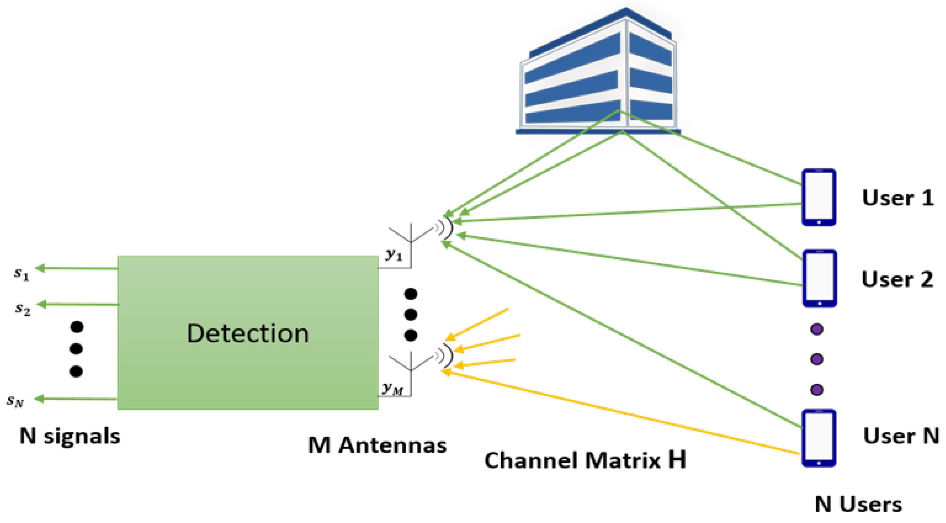
Figure 1. A Massive MIMO uplink system M base station antennas ( M > > N ) and N single antenna users with channel matrix H. All the user signal are superimposed at the base station.
Electronics 10 00578 g001
Figure 2. A Single Cell Massive MIMO uplink system M base station antennas and K single antenna users.
Electronics 10 00578 g002
Figure 3. A typical massive MIMO uplink operation with K single antenna users, M base station antenna ( M > > K ) , and channel matrix H. The uplink signal from simultaneously communicating users are superimposed at the base station. The decoder then separates the superimposed signals into individual data streams.
Electronics 10 00578 g003
Figure 4. Beam Pattern with different antenna configuration. (a) 16 base station antenna and 16 single antenna users. (b) 32 base station antenna and 16 single antenna users. (c) 64 base station antenna and 16 single antenna users. (d) 128 base station antenna and 16 single antenna users.
Electronics 10 00578 g004
Figure 5. Bit error rate (BER) performance of proposed SSORGS algorithm with 16 user terminals, 16QAM modulation and changing base station antenna. (a) 16 user terminals and 16 base station antenna. (b) 16 user terminals and 32 base station antenna. (c) 16 user terminals and 64 base station antenna (d) 16 user terminals and 128 base station antenna.
Electronics 10 00578 g005
Figure 6. BER performance of proposed SSORGS algorithm with various base station antenna configuration. This simulation was conducted with 16 user terminals and 16-QAM modulation configuration.
Electronics 10 00578 g006
Figure 7. BER performance of proposed SSORGS algorithm by switching the modulation order. This simulation was conducted with 16 user terminals (N) and 16 base station antennas (M) configuration.
Electronics 10 00578 g007
Figure 8. The proposed hardware architecture with all the required components designed for the SSORGS algorithm.
Electronics 10 00578 g008
Table 1. Simulation Parameters.
ParameterValue
Carrier Frequency3.7 GHz
System Bandwidth20 MHz
Signal to Noise Ratio0 dB–25 dB
Antenna Numbers at Base Station16–256
Channel ModelRayleigh Fading Channel Model (Uncorrelated)
Signal Variance2
Users16 Single Antenna Users
Frame duration10 ms
Sub-frame duration1 ms
Slot duration0.5 ms
Variance in NoiseChanges with SNR
Modulation Scheme64-QAM, 16-QAM, QPSK, BPSK
Table 2. Complexity comparison for proposed SSORGS algorithm.
AlgorithmComplexity
ZF O ( M N 2 )
MMSE O ( M N 2 )
GS O ( i N 2 )
CG O ( i N 2 )
SSORGS O ( i N 2 )
Publisher’s Note: MDPI stays neutral with regard to jurisdictional claims in published maps and institutional affiliations.