1. Introduction
Since 1957, when the space age started, rockets and satellites have been sent to space for several missions of telecommunication, remote sensing, navigation, meteorology, climate research and human-space exploration. Most of these objects have lost their originally activity over time, but still orbiting out of control around the Earth or reentering the atmosphere as space debris [
1]. In fact, nowadays only about 24% of the cataloged objects are satellites (less than a third of which are operational), and about 18% spent upper stages and mission-related objects [
2]. Both active satellites and space debris in orbit around the Earth, are defined as resident space objects.
Space debris represent a serious risk for every active satellites or spacecraft, because collisions between in-orbit objects can occur from every direction with speed up to 10 km/s. The fragments created by a collision can generate a cascading process, known as the “Kessler syndrome,” in which each collision between objects generates more space debris, which increases the probability of further collisions and consequently it could create new debris [
2,
3,
4]. Moreover, during the re-entering process, most space debris burn up in the atmosphere, but larger objects can reach the ground intact. The monitoring of all resident space objects is necessary to protect valuable space assets and, consequently, characterizing them is an essential task for space objects classification and risk assessment. In this context, the availability of efficient techniques for accurate estimation of motion and orbit parameters is extremely important.
In general, the most densely populated orbit is the Low Earth Orbit (LEO), between 200 km and 2000 km of altitude, where pieces of debris are denser than meteoroids. The United States Strategic Command (USSTRATCOM), which benefits from its Space Surveillance Network (SSN) [
5], maintains the largest database in the world of catalogued objects in LEO [
6], with about 24,000 trackable objects with sizes greater than 10 cm [
7]. Periodically, about every 8 h, the United States Joint Space Operations Center (JSpOC) analyzes the data collected by the SSN and performs orbit determination using its software based on Simplified General Perturbation 4 (SGP4), with the aim to create a file with a universal suitable format as well-known as the Two-Line Element set (TLE), which contains the orbital parameters of the object under consideration [
8,
9]. Public release of the TLE catalog has been accomplished for many years, first through NASA, and more recently through the Space-Track web site [
10]. In addition, Celestrak has maintained a web site for obtaining the TLE catalog for several decades [
11].
In 2015, with the aim to align with the United States, the European Commission started a dedicated framework for European Space Surveillance and Tracking (EUSST) in the space situational awareness program [
12]. The SST services assess the risk of in-orbit collisions and uncontrolled re-entry of space debris into the Earth’s atmosphere, and detect and characterize in-orbit fragmentations. Within this framework, a network of dedicated sensors (radars, telescopes and lasers) has been designed. Lasers and optical telescopes are employed for observations in Medium Earth Orbit (MEO), between 2000 km and 35,786 km of altitude, and in Geosynchronous Equatorial Orbit (GEO), above 36,000 km. Whereas, the principal technique used for the LEO debris monitoring is based on radar systems.
The analysis of the state-of-the-art shows that Europe can count on a large network of radar sensors with different technical features. The European Incoherent Scatter Scientific Association (EISCAT), for instance, operates three incoherent scatter radar systems, at 224 MHz, 931 MHz in Northern Scandinavia and one at 500 MHz on Svalbard [
13,
14]. All the EISCAT radars work in beam-parking mode and they are able to provide a peak power of few Megawatts, with a duty cycle of about 10–20% [
14]. Germany has available a powerful L-band bi-static radar composed of the FGAN Tracking and Imaging Radar (TIRA), located near Bonn, as transmitter antenna, and the Max Planck Institute Effelsberg Radio Telescope, as receiver system [
15]. In this configuration, the radar works in beam-parking mode and can transmit up to 2 MW peak power pulses, permitting the detection of objects with size down to 1 cm [
16]. In addition, the German Space Administration (DLR) is developing the German Experimental Surveillance and Tracking Radar (GESTRA), a close-monostatic pulsed phased array working in L-band (in the frequency range 1280–1400 MHz), able to carry out digital beamforming and designed to observe space objects up to 3000 km of altitude [
17,
18]. On the French side, the main radar employed all day for space surveillance in survey mode is the Grand Réseau Adapté à la Veille Spatiale (GRAVES), a military bi-static phased array radar operating at 143.05 MHz in continuous wave (CW) mode, located in Dijon [
19]. As concerns Spain, the Spanish Space Surveillance and Tracking (S3T) system is currently equipped with two radars: the Monostatic Space Surveillance Radar (MSSR), a close-monostatic L-band radar, located in the Santorcaz military naval base, and the new S3T Surveillance Radar (S3TSR) [
20]. In the United Kingdom, the Chilbolton Advanced Satellite Tracking Radar (CASTR) was developed starting from the Chilbolton radar, a fully steerable antenna, with a 25 m reflector, operating in S-band (at 3 GHz) with a peak power of 700 kW, located near Winchester (Hampshire). The CASTR is able to efficiently observe objects with Radar Cross Section (RCS) greater than 0.5 m
2 in LEO [
21]. All these European systems, although they present different technologies, are able to collect important information about space objects, such as slant-range and Doppler shift measurements.
Italy is also part of the EUSST program and has available two bi-static radars, based on a radio telescope as receiver, that operate in survey and tracking mode, respectively. They are the BIRALES system [
22] (Bi-Static Radar for LEO Survey), and the BIRALET system [
23] (Bi-Static Radar for LEO Tracking). Both bi-static radars have the same transmitter, named the Radio Frequency Transmitter (TRF) that works in the P-band at 410–415 MHz and supplies a transmitting power up to 10 kW. BIRALES is used for monitoring the space environment in survey mode. The receiver of the BIRALES radar is the Northern Cross Radio Telescope, located in the Medicina Radio Astronomical Station, near Bologna, in Northern Italy. The Northern Cross is a multi-beam system that performs Doppler shift, illumination time and received signal-to-noise ratio (SNR) measurements. It permits an estimation of the angular track of the object, that transits through its field of view, analyzing the beams illumination sequence. This innovative configuration allows the sensor to collect fundamental data useful to perform initial orbit determination [
24].
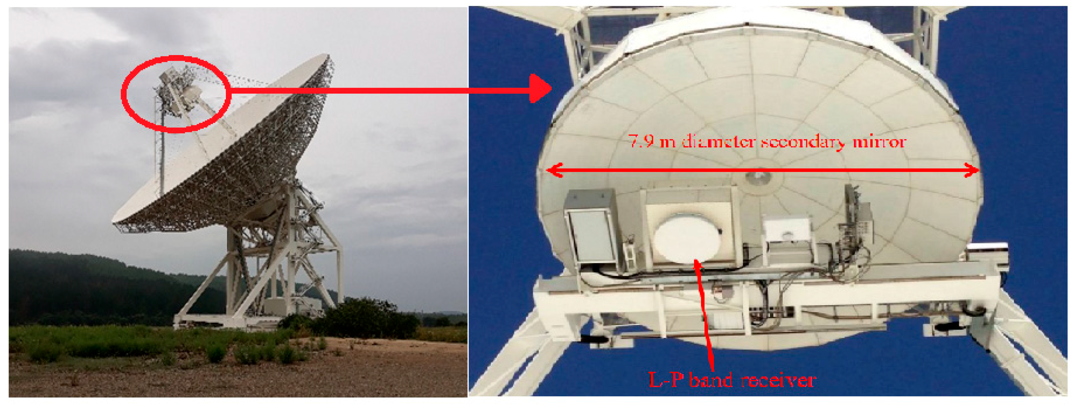
BIRALET, on the other hand, allows the space environment monitoring in both beam-parking and tracking modes. The receiver of the BIRALET radar is the Sardinia Radio Telescope (SRT), a 64-m dish fully steerable wheel-and-track antenna, located near San Basilio (Cagliari, Sardinia, Italy). It represents a flexible instrument utilized for radio astronomy research and space science, developed to operate in a large frequency range between 300 MHz and 110 GHz [
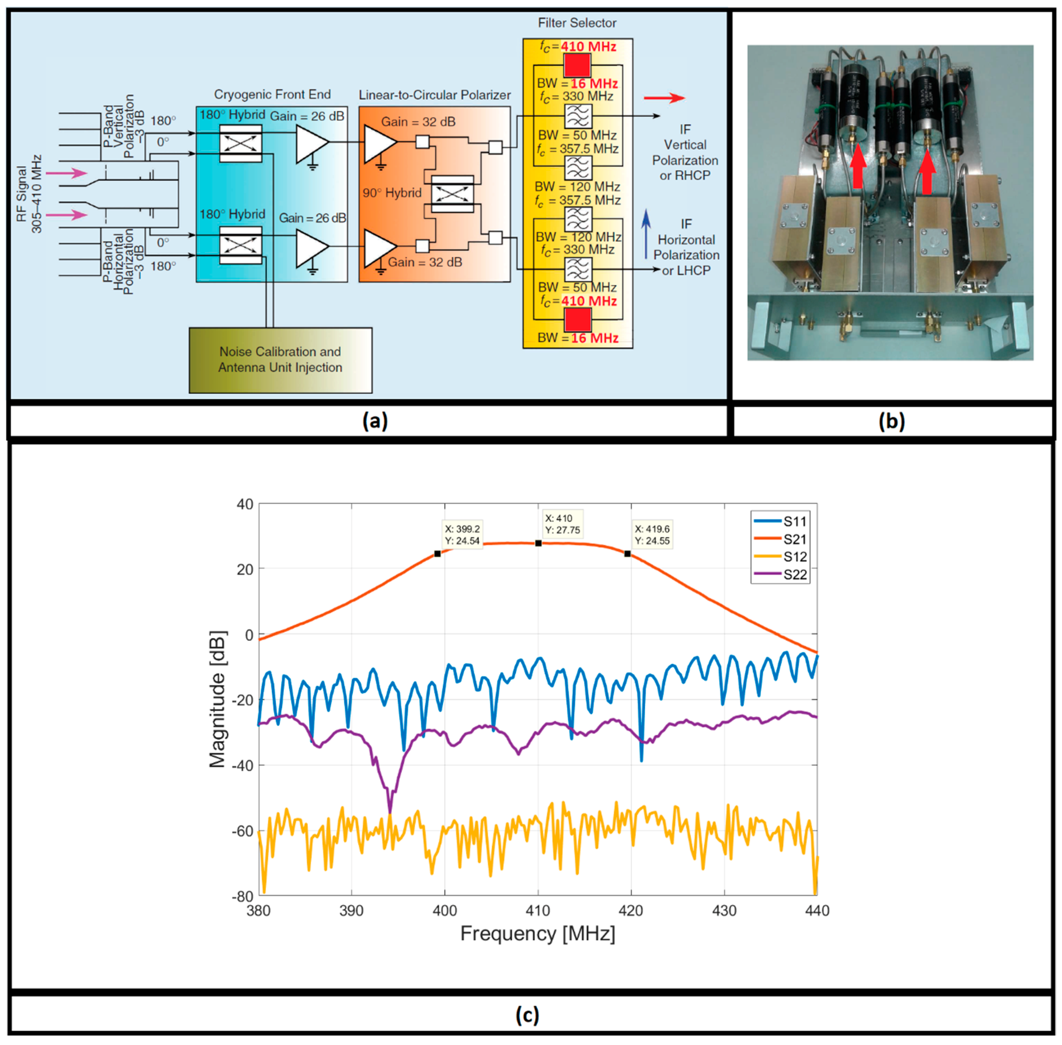
25]. The antenna is a multi-reflector system with a quasi-Gregorian configuration, with a 64-m parabolic primary mirror and a 7.9 m elliptical secondary mirror. The telescope has three other mirrors (two with a diameter of 2.9 m and one with a diameter of 3.9 m), which provide the Beam Wave-Guide (BWG) system. Thanks to these reflectors, the system has available six focal positions (the primary focus, the Gregorian focus, and the four BWG foci) and it is able to host up to twenty remotely controllable receivers and to observe the sky with high efficiency in the frequency range between 0.3–116 GHz. Since the TRF antenna operates in P-band, the SRT front-end used for space debris monitoring is the P-band receiver, which is installed in the primary focus of the telescope. Compared to the early years when SRT was used for space debris measurement campaign [
26], where the back-end was based on a spectrum analyzer [
27] with its limitations (i.e., the slow frequency sweeps for low resolution bandwidths and the resulting lack of the real-time data storage function), the system was upgraded with a dedicated channel, that guarantees a more efficient data collection during the observations of space objects. The (then) new dedicated channel consisted of a back-end, with its acquisition chain, based on the Red Pitaya electronic board [
23,
25,
27]. Whereas, the configuration with the spectrum analyzer remained available for maintenance and testing operations, where it was necessary to view immediately the echo radar in the instrument display, without a post-processing function. Both these back-ends performed only Doppler shift measurements, with an accuracy of few dozens of Hertz. However, a fundamental aspect for orbit determination processes is represented by also slant-range measurements. In fact, the combined use of Doppler shift and slant-range measurement would grant both an increase in the object state estimate accuracy and a reduction in the estimate uncertainty [
25]. For this reason, and with the aim to align with the others European radars involved in operations of space surveillance and tracking, the BIRALET system has recently been improved with the development of a new ad hoc back-end based on the National Instrument USRP-2954R board [
28], in order to measure both the slant-range and the Doppler shift, simultaneously. As concerns the receiving system of BIRALET, this new back-end replaced therefore the former based on the Red Pitaya board, that did not include, due to its limited performances [
23], an ad-hoc software for processing slant-range measurements and therefore it performed only Doppler shift, with an accuracy of few tens of Hertz. The new back-end has been developed with the aim to maintain a distance error lesser than 100 m and a Doppler shift error up to 50 Hz, according to the EUSST program requirements.
In this paper, the front-end and the new back-end of the Italian BIRALET radar are described. In particular, a detailed description of the new transmitting and the new receiving systems are presented, focusing on the architecture, implemented on the USRP-2954R board (NI, Austin, TX, USA), to perform Doppler shift and distance measurements. Finally, the results of several validation campaigns are presented, comparing the measured values with the estimated ones.
3. The Receiver Acquisition Chain and the Ad Hoc Back-End of the BIRALET Radar
Since 2014 [
26], SRT is employed in space situational awareness activities and consequently it has been equipped with a dedicated channel for space debris observations. This channel might have three main configurations on the basis of the utilized back-end. In fact, three back-ends based respectively on the spectrum analyzer, the Red Pitaya board and the new National Instrument USRP-2954R board (NI, Austin, TX, USA), are available [
27]. Each configuration needs of a dedicated acquisition chain in order to carry the RF signal from the SRT feed to the back-end. With respect to the two previous back-ends (the spectrum analyzer and the Red Pitaya board) that performs only Doppler shift measurements, a new ad hoc back-end was necessary in order to permit also slant-range measurements. This characteristic represents a fundamental aspect for orbit determination processes because the combined use of Doppler and range measurement would grant both an increase in the object state estimate accuracy and a reduction in the estimate uncertainty [
25].
For this reason, an ad hoc architecture based on the National Instrument USRP-2954R board [
28] has been developed for both the transmitting and the receiving system. Thanks to its high performances and its completeness in terms of kind of measurements that can perform (i.e., the Doppler shift and the slant-range, simultaneously), the new back-end replaced the old back-ends and it has become the main signal acquisition system of the BIRALET radar. The USRP-2954R board is a 10 MHz to 6 GHz Tunable RF Transceiver that contains a GPS-disciplined oscillator (GPSDO), which enables you to lock the internal clocks to a GPS reference signal, synchronize using GPS timing information, and query GPS location information [
28]. The main features of the board in transmitting and receiving mode are reported in [
28].
The transmitter architecture of the TRF antenna and the kind of transmitting waveform is described in
Section 3.1. The receiver architecture of the SRT dedicated back-end is described in
Section 3.2.
3.1. Transmitter Architecture of the TRF Antenna Based on the USRP-2954R Board
As mentioned above, the new back-end of the BIRALET radar, funded and developed under the European Space Surveillance and Tracking (EUSST) program [
12], is based on a National Instrument USRP-2954R board. The same USRP-2954R board has been installed on both the TRF and SRT antennas in order to transmit a well-known signal (that will be explained in more detail below) which permits slant-range and Doppler shift measurements, simultaneously, according to the EUSST program requirements.
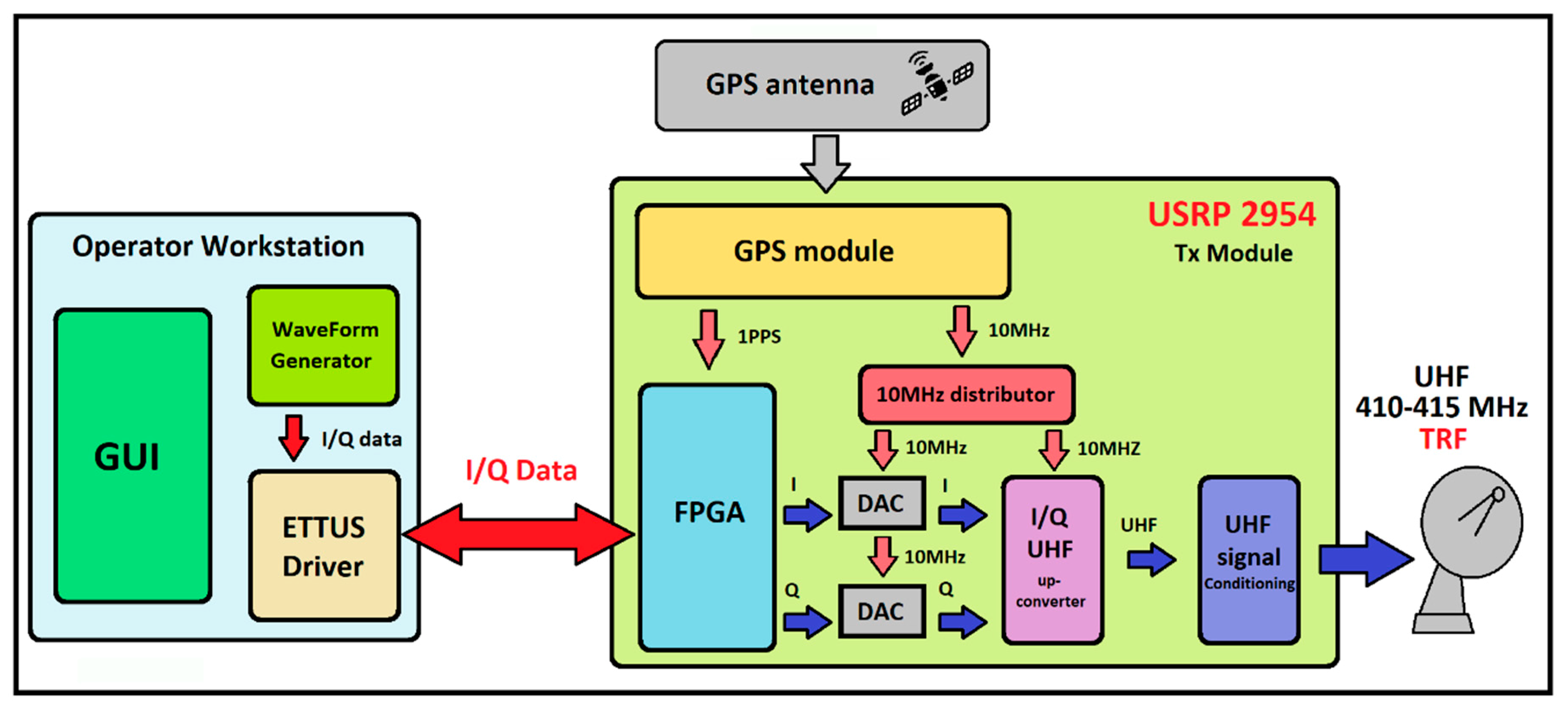
In detail, the USRP-2954R board is part of the transmitter architecture, which is shown in
Figure 4, with the aim of generating the I/Q samples of the waveform to send out. The waveform is chosen by the operator, using the Operator workstation with a dedicated Graphical User Interface (GUI) and a waveform generator (see
Figure 4), on the basis of the specifications required by the observation scenario. The I/Q samples are then converted into an analogue signal by two 16-bit DACs and up-converted by the I/Q up-converter chip, in order to have a signal in the frequency range 410–415 MHz, indicated as ultra-high frequency (UHF) signal in the block diagram of
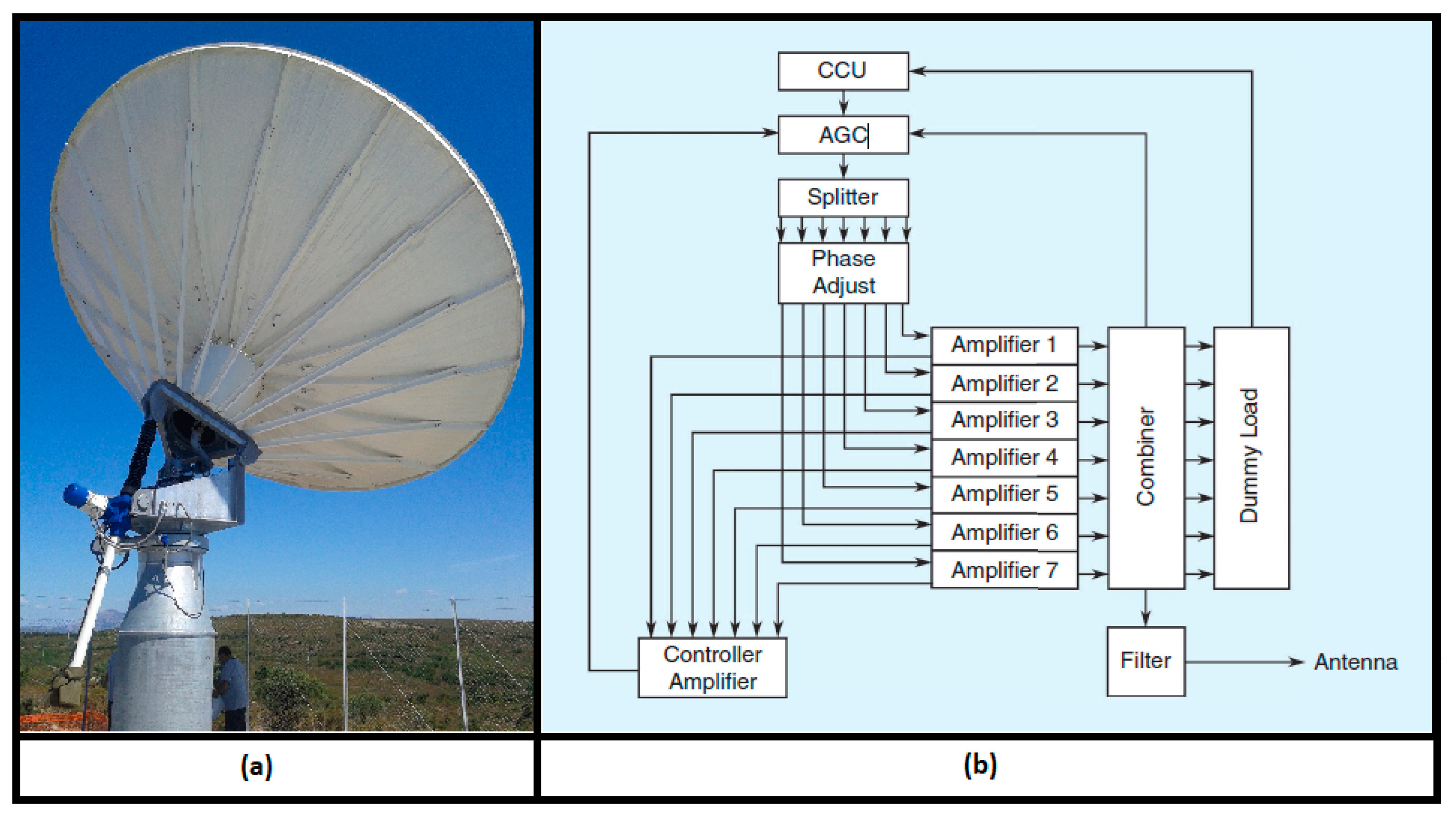
Figure 4. This UHF signal is then amplified thanks to the up to 10 kW power amplifier of TRF, described in
Section 2.1 (see
Figure 1b). Finally, the UHF signal is transmitted towards the expected target position (considering the antenna pointing coordinates predicted propagating the TLE with the SGP4 software [
9]).
The overall performances of the radar are also determined by the synchronization accuracy of the TRF and SRT systems. The receiver and the transmitter are synchronized in time and frequency using the GPS one pulse per second (1 PPS) and the 10 MHz reference signals of the GPSDO module of the USRP-2954R board. In particular, the 10 MHz signal is used as reference for all down-conversions and sampling frequency generation (ensuring no drift between transmitter and receiver). On the other hand, the 1 PPS signal is used to start the acquisition/generation between receiver/transmitter, simultaneously. The GPSDO module of the USRP-2954R board guarantees a maximum error of 10−7 s, that means 30 m in distance, according to the EUSST program specifications.
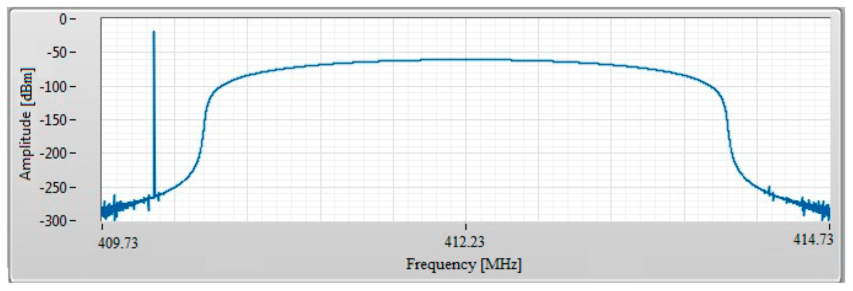
The system has been developed with the aim to detect debris at a maximum range of 3000 km with an accuracy of about 30 m (as explained in the previous lines) and to perform also Doppler shift measurements with an accuracy of few Hertz. For this reason, the waveform transmitted by TRF is a mixed signal composed of a frequency modulation continuous wave (FMCW) signal, known better as chirp, plus a CW tone, with an overall bandwidth of 5 MHz, as shown in
Figure 5.
In particular, the transmitted signal is set to a central frequency of 412.23 MHz, with the CW tone generated with an offset frequency of −2.145 MHz from the central one. Regarding the chirp, it is a down-chirp in the range between 410.43 MHz and 414.03 MHz, with a pulse repetition interval (PRI) of 20 ms and a pulse repetition frequency (PRF) of 50 Hz. This guarantees a slant-range measurement of objects at distances up to 3000 km, as shown by the following formula [
32]:
where
c is the speed of light and d is the maximum range, in this case equal to 3000 km. This value of PRF prevents the possibility of Doppler measurements using only a pulsed signal, because typical space debris Doppler shift values in LEO are in the range of a few kilohertz (in P-band), values greater than our PRF. For this reason, the system transmits a mixed signal based on the chirp plus the CW tone, in order to work as a pulsed radar (for slant-range measurements) and as a CW radar (for Doppler shift measurements).
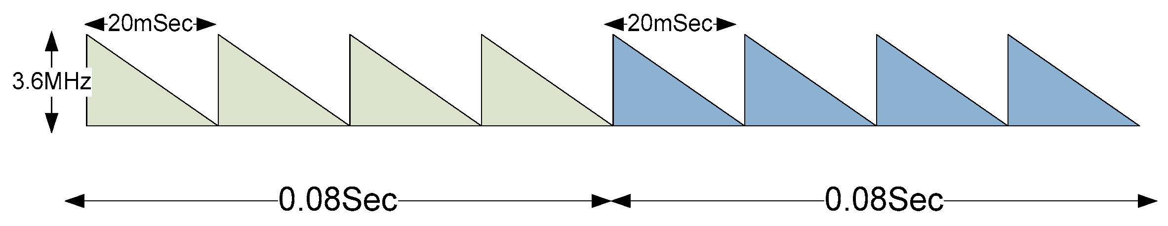
A sampling frequency of 5 MS/s is used and the maximum RMS transmitting power is, as mentioned above, equal to 10 kW, with a 100% duty cycle. Using a 100% duty cycle allows to use the whole energy of the transmitter (there is no coupling between transmitter and receiver) and the 50 Hz PRF permits to measure the range without ambiguities (the Doppler information, to compensate the range error, is extracted from the CW tone). The choice of a 3.6 MHz chirp allows to exploit all the available bandwidth, maximizing the range resolution and reserving a small portion of the band for the CW tone useful for Doppler extraction. This guarantees to measure a maximum Doppler shift of more than 100 kHz, which can be considered more than sufficient, given the expected target speed in LEO with the used carrier at about 410 MHz.
In order to maximize the signal-to-noise ratio (SNR) for the range extraction, a matched filter has been implemented with the aim of performing a pulse compression. The inter-pulse integration is also used by the addition of four chirps (see
Figure 6). This aspect means that a measurement of the target range and Doppler shift is performed every 80 ms (the step between each measure is four pulses: 20 ms × 4 = 80 ms). Finally, both range and Doppler shift measurements are time stamped with a millisecond accuracy, allowing precise target trajectory prediction.
3.2. Receiver Architecture of the SRT Dedicated Back-End Based on the USRP-2954R Board
As mentioned above, the same National Instrument USRP-2954R board has been also utilized in the receiver antenna of the BIRALET radar: the SRT system. This new back-end replaced the former based on the Red Pitaya board, that did not include, due to its limited performances [
23], an ad-hoc software for measuring also slant-range and therefore it performed only Doppler shift, with an accuracy of few tens of Hertz. A dedicated acquisition chain is necessary in order to carry the RF signal from the SRT feed to the USRP-2954R board, as shown in
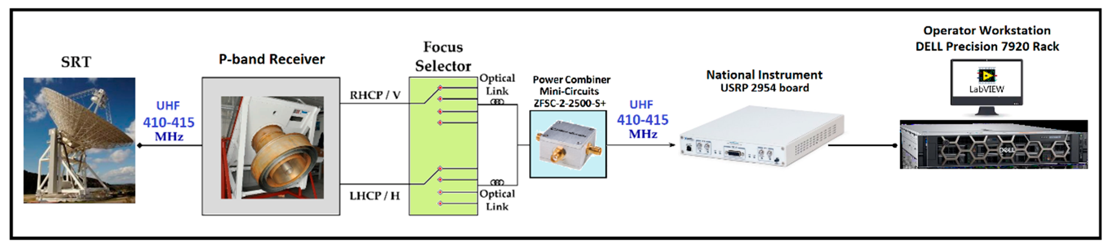
Figure 7. Analyzing this acquisition chain, it is clear that the RF signal (the UHF radar echo at 410–415 MHz, in space debris observations) is detected by the SRT antenna thanks to its P-band receiver, described in
Section 2.2. After the P-band receiver block, the RF signal comes into the focus selector block, which enables to set the antenna focus necessary for the observation (the primary focus in the case of space debris observations with the P-band receiver) and provides an overall gain of about 20 dB. From the top of the primary focus, the UHF radar echo is then transported to a shielded room at ground level, due to a 500 m optical link. After that, the two polarization channels of the P-band receiver are combined using a Power Combiner (ZFSC-2-2500-S+ model from Mini-Circuits (Mini-Circuits, Brooklyn, NY, USA) [
33]) and subsequently the combined UHF signal at 410–415 MHz is processed by the USRP-2954R board.
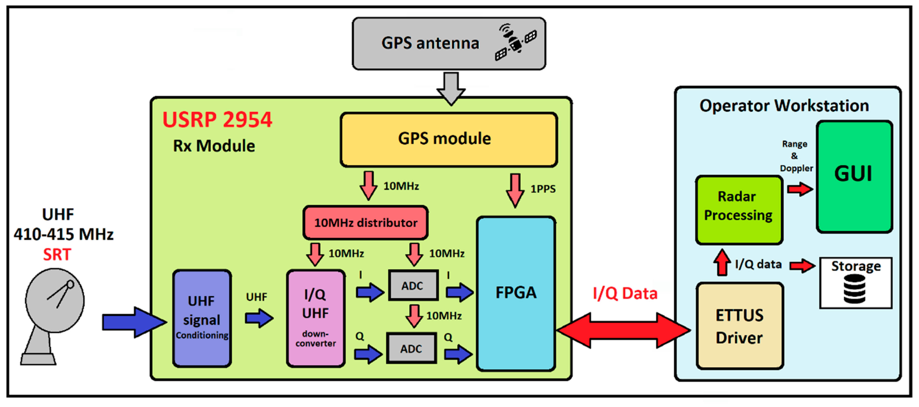
The receiver architecture is shown in
Figure 8, where the receiving chain depicted in
Figure 7 is summarized with the SRT logo. In particular, the UHF signal enters in the USRP-2954R board and it is down converted to the board baseband (10 MHz to 6 GHz, as reported in [
28]) by an I/Q down converter chip and finally digitalized by two 14-bit ADCs. The I/Q signals are then sent to the DELL Precision 7920 Rack (see
Figure 7) Operator workstation for processing. The workstation is equipped with the ETTUS drivers of the USRP-2954R board, a LabView Radar processing program and a dedicated user-friendly GUI. The processing task can be done both in real-time mode or in offline mode, by using the real time stored I/Q samples. This feature is extremely useful for testing purposes and for analyzing further improvements of the radar processing chain.
The LabView Radar processing program is developed in order to perform the pulse compression technique and, consequently, to extract slant-range and Doppler shift measurements of the detected target. As mentioned in
Section 3.1, a matched filter is implemented for correlating the well-known transmitted signal, or template, with the unknown received signal to detect the presence of the template in the unknown signal. The matched filter is the optimal linear filter for maximizing the SNR in the presence of additive stochastic noise.
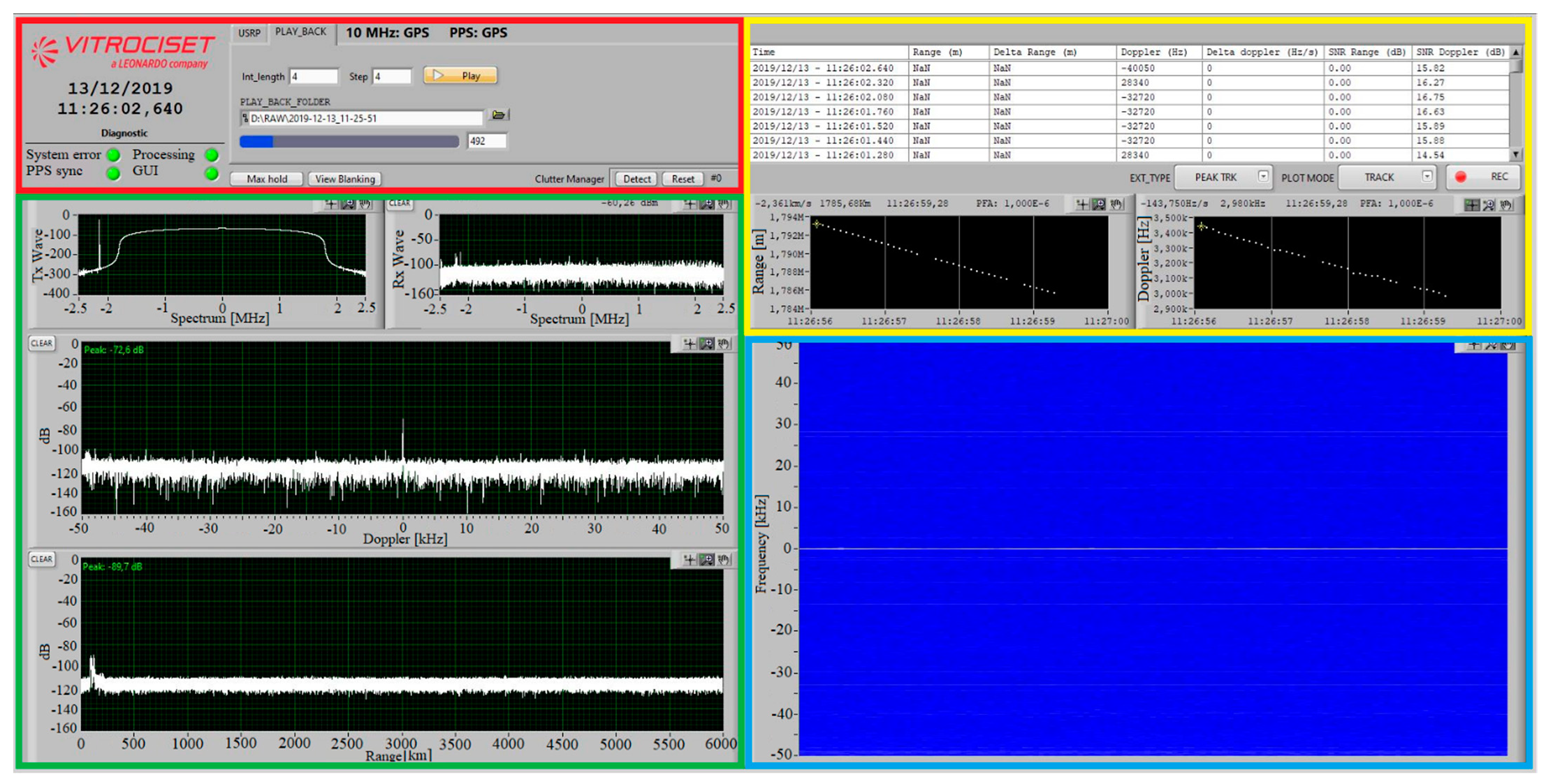
A screenshot of the Operator workstation GUI is shown in
Figure 9. The GUI is composed of four main blocks (see
Figure 9): the control panel and status display (red block), the 2D plots (green block), the slant-range and Doppler shift extractor (yellow block) and the spectrogram plot (blue block).
In detail, the control panel and status display (red block) allows two operating modes: USRP mode (data elaboration in real-time) and playback mode (data elaboration in post-processing). However, both operating modes save data in real-time. In addition, the epoch stamp and four diagnostic leds are available in the red block. These diagnostic leds indicate when there are system errors, the state of the data processing, the state of the 1PPS synchronization and the update state of the GUI plots. There are also available some functions for 2D plots, such as the max hold function and the view blanking function (which permits a graphical filtering of undesired signals).
The 2D plots section (green block) is composed of four plots:
Tx wave plot: graphical representation of the transmitted signal (both frequency and time domains are available);
Rx wave plot: graphical representation of the received signal (both frequency and time domains are available);
Doppler plot: graphical representation of the received signal versus the frequency variation (in this plot, it is unavoidable to view the transmitting carrier, given the baseline between TRF and SRT of only 20 km);
Range plot: graphical representation of the received signal versus the distance variation.
In the slant-range and Doppler shift extractor (yellow block) section, observation data (epoch, range, Doppler and received SNR) are listed in a table. In addition, there are two 2D plots for range and Doppler representations versus time variation, respectively.
Finally, a spectrogram of the observation window is available in the blue block (spectrogram plot).
4. Results of Space Objects Measurement Campaigns
A validation campaign of the new system, based on the USRP-2954R board, was performed with the goal to assess the BIRALET radar performances. Targeted observations were performed, between 13 December 2019 and 9 October 2020, by pointing the system towards calibration objects from the International Laser Ranging Service (ILRS) database, which provides the positional state of the satellites with an accuracy of around a centimeter, and other NORAD target objects, for which the expected range and Doppler shift values were estimated using the available TLEs. The population and related TLEs were retrieved from the Space-Track website [
9,
10,
11]. In these calibration campaigns, the BIRALET radar detected 37 objects.
All the observations were made in beam-parking mode, waiting for the objects to cross the Field of View (FOV) of our radar, with a transmission power of about 5 kW. The list of the scheduled passages and measurement results for the debris, complete with the detection time for each object, the estimated RCS, the estimated and measured slant-range and Doppler shift values, is reported in
Table 2.
Before the observations, a forecasting campaign was made in order to obtain the azimuth and elevation pointing coordinates and to predict the slant-range and the Doppler shift frequency projected onto the line of sight of the radar. An algorithm based on the reading of the TLEs provides these pieces of information and consequently it simulates the passages of the objects. In detail, after establishing a temporal window for the observation, for each catalogued object of the list available on the Space-Track web site [
10], the software propagates its TLE by means of the SGP4 dynamical model and computes possible passages that could be detected by BIRALET. After that, it is possible to choose the desired passage, by selecting the objects passage epoch and their azimuth and elevation pointing coordinates, in order to perform the validation observation. A passage is considered detectable if the constraints on the receiver and transmitter minimum elevation are satisfied, and the detected SNR is larger than an imposed threshold (typically 6 dB). For each detectable passage, the software provides a list of time epochs and required pointing directions, i.e., SRT and TRF azimuth and elevation, and the estimated values of the Doppler shift and the slant-range. For the considered simulations, the TLE propagated with the SGP4 dynamical model represents the real dynamics of the system. After the measurement campaign, it is possible to compare the measured Doppler shift and slant-range with the estimated values and investigate if the observation was successful. This aspect can be considered true when the object is detected and its measured parameters match the EUSST requirements (distance error lesser than 100 m and Doppler shift error up to 50 Hz).
As described in
Section 3.2, the Operator workstation GUI provides all observation information, i.e., the measured slant-range and Doppler shift. In addition, several plots are available in order to show the measured values to the user, immediately.
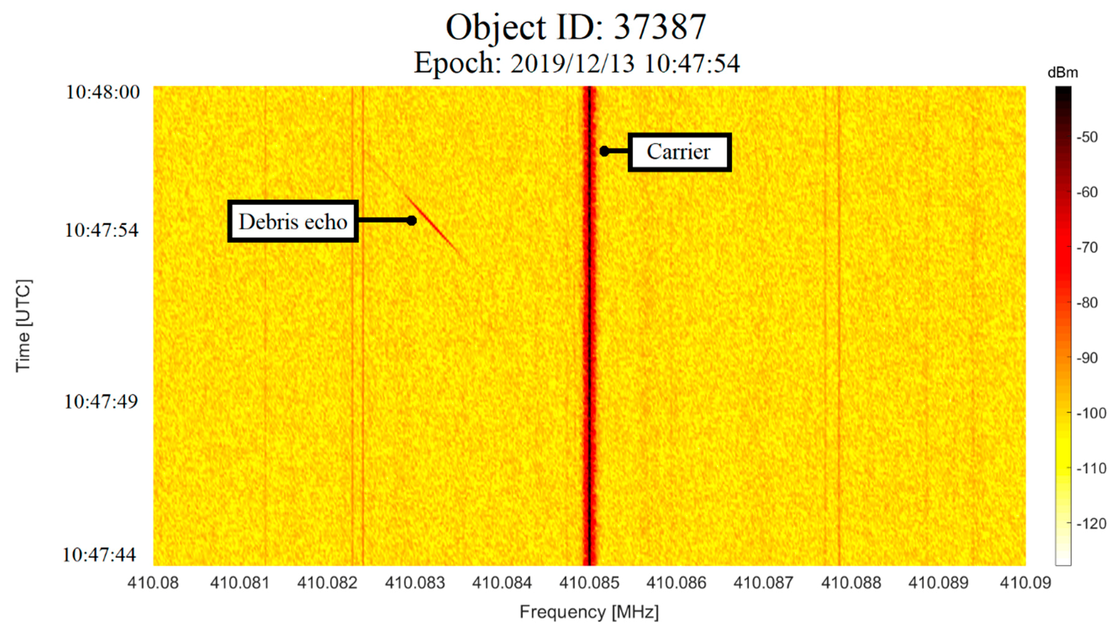
Purely by way of example, the spectrogram of the entire observation window for the object ID 37387, detected on December 13, 2019 at 10:47:54 UTC, is shown in
Figure 10. Due to the relative close proximity of TRF with the SRT antenna (baseline between the two antennas of about 20 km), the receiving antenna (SRT) of the BIRALET radar was able to receive the carrier frequency (410.085 MHz), which is clearly visible in the image (
Figure 10). Additionally, in the spectrogram (
Figure 10), it is recognizable the frequency swipe of the debris echo, due to its high velocity, as it moves toward the receiver position (when the echo is located to the left of the carrier, which implies a negative Doppler shift). In this case, the measured Doppler shift is equal to −1740 Hz.
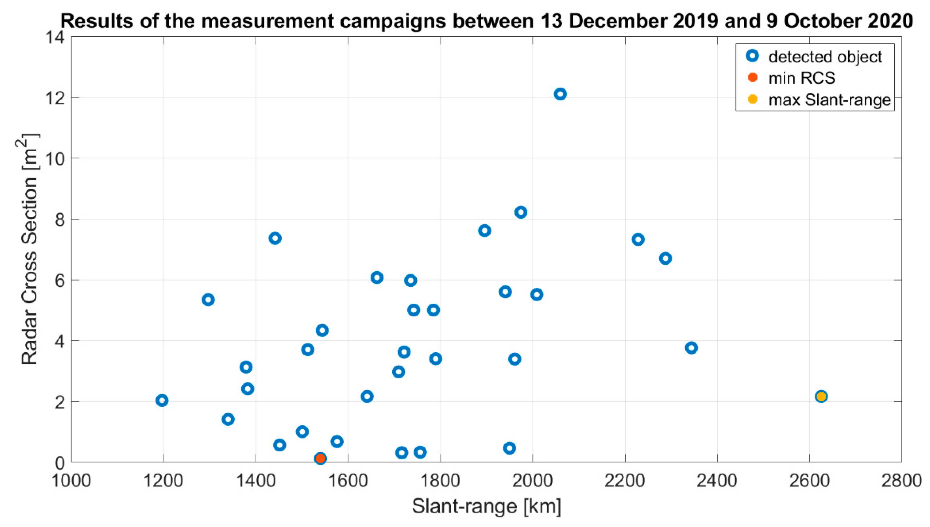
In
Figure 11, the results of the all validation measurement campaigns are summarized. In particular, the whole known RCS observed objects are indicated considering their measured slant-range as a function of their RCS. Analyzing the results (
Figure 11), it is possible to see that the smaller object (ID object 39427 with a RCS of 0.1199 m
2), indicated with a red point, was detected at a slant-range of about 1500 km (1540.158 km, to be exact, as reported in
Table 2). This represents a great result, for the BIRALET radar, which demonstrates its high performances in small space debris observations with RCS lesser than 1 m
2. This aspect is confirmed by 6 other objects with RCS lesser than 1 m
2 (see
Table 2 and
Figure 11), detected at distances between about 1400 and 2000 km.
The most distant object was detected at a slant-range of about 2600 km (2624.938 km as listed in
Table 2). It is the object with ID object 1328 and a RCS of 2.16 m
2 and it is highlighted with a yellow point in
Figure 11.
The rest of the observed objects has RCSs from 1 m2 to about 12 m2 and they were detected at distances between about 1200 and 2400 km.
5. Discussion
A calibration measurement of the receiver chain was performed before starting the observation campaigns, with the aim to investigate the received signal delay. In this way, the time error and consequently the range error, caused by the receiver chain from the P-band receiver to the dedicated backend based on the USRP-2954R board (see
Figure 7), was compensated. After this important calibration, a set of 37 objects were detected between 13 December 2019 and 9 October 2020 to compare measured Doppler shift and slant-range with the data available from the associated accurate ephemerides and results of the TLEs propagation using SGP4. The transmitting power of TRF was set to 5 kW.
As mentioned above, the EUSST program requires a distance error lesser than 100 m and a Doppler shift error up to 50 Hz. In order to meet these requirements, the ad-hoc system based on the USRP-2954R board has been developed for the BIRALET radar. In the validation measurement campaigns, 37 objects were detected at various distances in the range between 1200 km and 2600 km, as stated above. With the aim to validate the system, the slant-range error and the Doppler shift error have been evaluated considering the absolute value of the subtraction between the estimated value and the measured value.
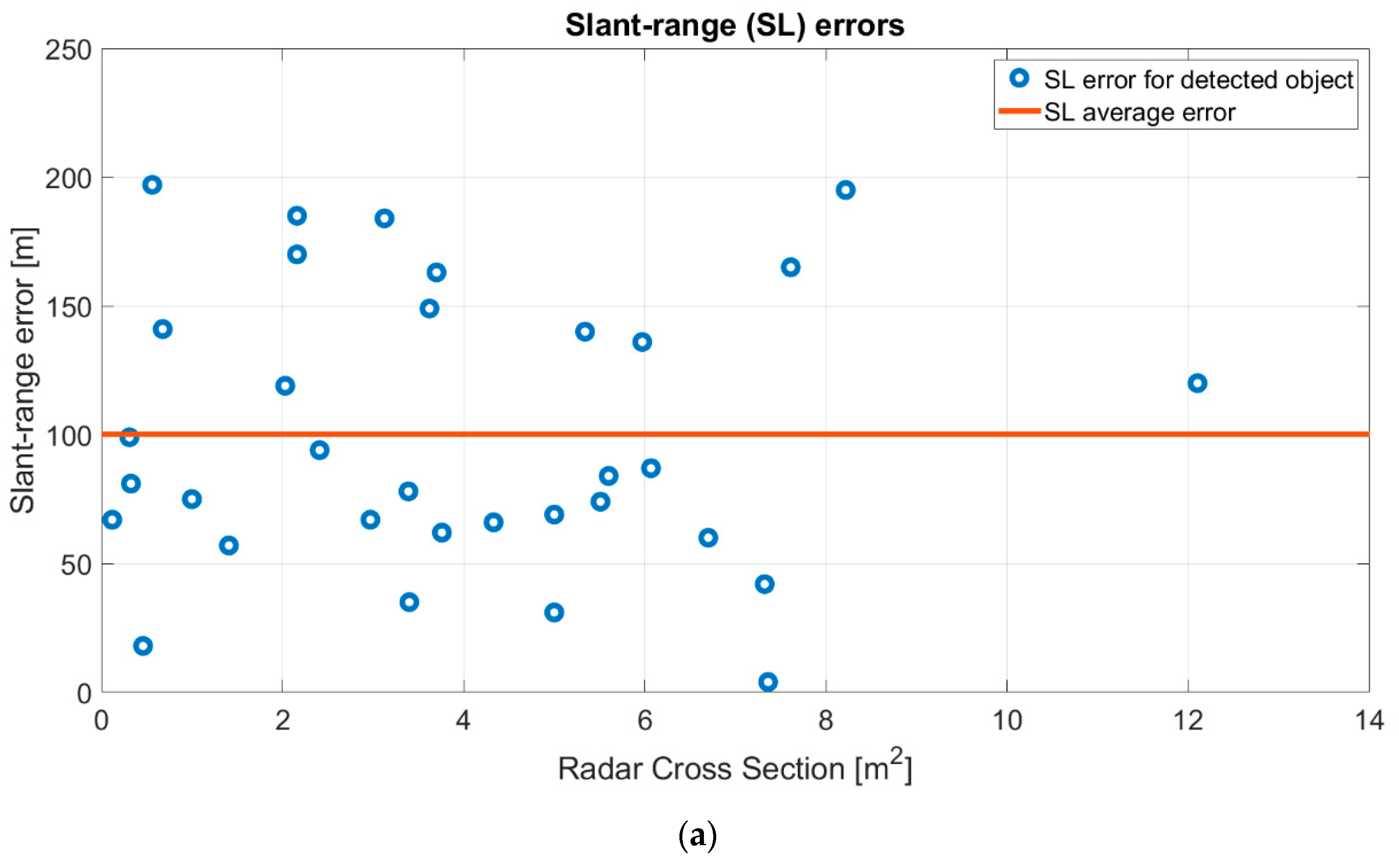
The slant-range error for each debris is reported in the graphical representation of
Figure 12a. The red line represents the slant-range average error for all detected objects, which is equal to 100.189 m with a calculated standard deviation of 54 m, which is in line with the EUSST requirements. In detail, 20 known RCS objects were observed with a slant-range error lesser than the average error. This represents a significant result that certifies the acceptable performances of the BIRALET radar in the EUSST program. Regarding observed debris with a slant-range error greater than the average error, their TLE could be inaccurate at the moment of the forecast campaign with a consequently pointing coordinates calculation error. The positive aspect is represented by the detection of the objects and the consequently data collection about them, useful for a new characterization of the object position.
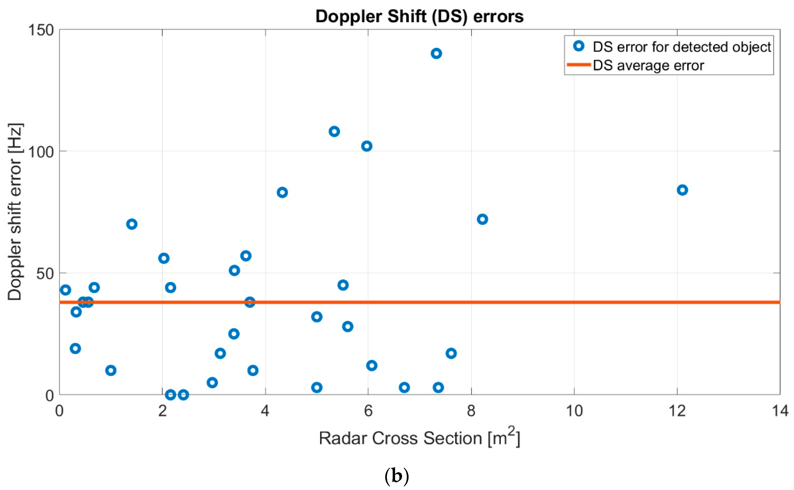
The Doppler shift errors, on the other hand, are represented in
Figure 12b. The average Doppler shift error is equal to 37.95 Hz, with a calculated standard deviation of 33.3 Hz, and it is depicted with the red line in
Figure 12b. The majority of the observed objects were detected with a Doppler shift error that respects the EUSST requirements.
6. Conclusions and Future Work
The BIRALET system is a bi-static radar that collects useful data for space debris studies under the EUSST program. In this paper, a new ad-hoc back-end for the BIRALET radar has been developed and presented, with the aim to perform slant-range and Doppler shift measurements, simultaneously. The BIRALET system is composed of the TRF antenna as transmitter, that permits, thanks to its new back-end based on USRP-2954R board, to transmit a mixed signal (CW tone plus FMCW signal) in order to perform range and Doppler shift measurements. The receiver is the SRT antenna, equally equipped with a new dedicated back-end based on the same USRP-2954R board.
Validation measurement campaigns were done in beam-parking mode in order to investigate on the system performances. The results, with the detection of 37 objects between 13 December 2019 and 9 October 2020, confirm that the measurements collected by the BIRALET radar, after calibration and bias correction, are accurate and comply with the EUSST requirements (i.e., a slant-range accuracy of 100 m and a Doppler shit error up to 50 Hz). In particular, the system was able to detect resident space objects with various RCSs, from 0.1199 m2 to 12.1 m2, at distances between about 1200 km and 2600 km, with an average slant-range error of 100.189 m, with a standard deviation of 54 m, and an average Doppler shift error of 37.95 Hz, with a standard deviation of 33.3 Hz.
An improvement of the system could be done by increasing the integration time (increasing the number of integrated pulses of
Figure 6) or changing the transmitted waveform. Many tests could be done by tuning the system parameters, and by processing the real time stored I/Q samples offline. Further measurements and processing refinements will be made in the next future, in order to try improving the system performances. The evaluation will be tested on coverage and accuracy, using several targets with different RCSs and orbiting at several altitudes.
Furthermore, since BIRALET is tested in beam-parking mode until now, waiting for the objects to cross the field view of the radar, one future work is represented by tracking mode observations, where the radar will follow the target. Thanks to this observation mode, BIRALET will have the possibility to observe the same object during its motion, in the whole time window of its visibility. In this way, a larger amount of data will be collected, such as the pointing coordinates (object position in the time window), the measured range and the measured Doppler shift, between the beginning epoch and the end epoch of the observation time period. These data will permit to graph the object trajectory as a function of the time and, consequently, to have also information about its 3D velocity respect to the observation position.
One of the physical limitations of the current BIRALET system could be the relatively low mechanical pointing speed of the SRT (0.85 deg/s in azimuth, 0.5 deg/s in elevation, as listed in
Table 1) and the availability of only one beam, resulting in a limited FOV (HPBW of 0.8 degrees, as reported in
Table 1). Space debris, with angular speeds greater than the maximum antenna angular movement, cannot be tracked. In addition, it proves impossible to measure the object trajectory direction with only one beam, as the case of the actual P-band BIRALET radar. Imaging the sky with a multi-beam receiver would increase the telescope field of view and survey speed, allowing the coverage of a greater portion of the sky in less time [
34]. One way to do it, as a future project, would be to develop a C-band Phased Array Feed (PAF) as receiver for the primary focus of the SRT system. The choice of the C-band guarantees an improvement of the antennas gain and consequently the possibility to detect objects at greater distance still. A PAF is made up of closely packed antenna elements that, by spatially sampling the focal plane, can synthesize multiple independent beams. Beam shapes and directions are controlled electronically by weighting the amplitudes and phases of the signals applied to the individual antennas by a beam-former [
35,
36,
37,
38]. Consequently, through the beam-forming process, PAFs are able to synthesize multiple beams and optimize each of them, enhancing aperture efficiency as well as effective FOV. The beam shapes and side lobes can be modified in real time and be set to minimize their response, in relation to undesired radio frequency interferences.


