Abstract
Autonomous unmanned aerial vehicles work seamlessly within the GPS signal range, but their performance deteriorates in GPS-denied regions. This paper presents a unique collaborative computer vision-based approach for target tracking as per the image’s specific location of interest. The proposed method tracks any object without considering its properties like shape, color, size, or pattern. It is required to keep the target visible and line of sight during the tracking. The method gives freedom of selection to a user to track any target from the image and form a formation around it. We calculate the parameters like distance and angle from the image center to the object for the individual drones. Among all the drones, the one with a significant GPS signal strength or nearer to the target is chosen as the master drone to calculate the relative angle and distance between an object and other drones considering approximate Geo-location. Compared to actual measurements, the results of tests done on a quadrotor UAV frame achieve location accuracy in a robust environment inside the exact GPS longitude and latitude block as GPS-only navigation methods. The individual drones communicate to the ground station through a telemetry link. The master drone calculates the parameters using data collected at ground stations. Various formation flying methods help escort other drones to meet the desired objective with a single high-resolution first-person view (FPV) camera. The proposed method is tested for Airborne Object Target Tracking (AOT) aerial vehicle model and achieves higher tracking accuracy.
1. Introduction
Only Global Positioning System (GPS)-based navigational modules can lead to flight instability if the GPS sensor is obstructed/faulty/jammed during the flight period. GPS drone navigation with computer vision, Radio Frequency (RF), or sensor-based navigation support technology can increase stability and reduce the chance of flight failure. Many vision-based sensors and modules are in usage in combination with GPS. Nowadays, computer vision has become a part of data analysis and navigation. However, computer vision-based methods need high-end data compiler units on-board or separate ground station-based data processing and control units. A simple, user-oriented, and flexible drone navigation system design is a desirable goal. A survey conducted on computer vision for aerial vehicles [1] refers to different navigation methods like visual localization and mapping with three-dimensional (3D) modeling, obstacle detection, and aerial target tracking. Such computer vision-based systems force drones and surveillance systems to increase the ease and accuracy of reliable output. In the visual localization and mapping method, the system builds a three-dimensional point cloud model for position estimation and localization with pre-existing data sets in any unknown environment [2,3], relying on the stereo camera and sensors like Light Detection and Ranging (LiDAR). Data storage and comparison with real-time data need significant processing capability. Visual localization and mapping depend on illumination conditions and require higher processing time in dense and complex environments. An overall security apparatus starting from the stealth monitoring IoT device [4], indoor navigated robotic agent for indoor surveillance, and target tracking-based drone system provides a new age solution for any organization.
The GPS signal-based navigation systems have limitations of multi-path reflectivity in an indoor environment. A Received Signal Strength Index (RSSI)-based indoor navigation method is helpful in path planning and localization of the robotic system in indoor environment using wireless nodes. Using the Random Forest-based classification method, this RSSI-based indoor navigation system is implementable on aerial vehicles [5]. This method, which has been tested on ground robots, has achieved higher accuracy compared to other RF-based navigation methods. The RSSI values of different wireless nodes are measured along with link quality at different positions to map the area. A neural network-based prediction model identifies the agent’s current position inside the mapping area [6]. The accuracy of GPS-based navigation techniques deteriorates in environments such as urban areas, indoor places, or forests. The best way to reduce such errors is to combine the information obtained by GPS and the drone’s internal localization system as proposed by Yoo et al. [7] and Beard et al. [8]. However, the data received rely on the signals from external satellites and the number of satellites.
A computer vision-based navigation method suggested by Kim et al. selects the region of interest and tracks to navigate the drone in GPS navigation denied-areas for surveillance missions [9] with an onboard aerial camera facing downwards. In this method, morphological operations and template matching methods aid the calculations over the x and y planes. Elsewhere, a real-time vision system for autonomous cargo transfer between two platforms is developed with a camera positioned parallel to the ground for ellipse tracking and detection [10]. Researchers also explore the integration of Internet of Things (IoT) and drone computing methods. One of them is a cloud-based IoT system that helps to track and follow an object [11], but it requires uninterrupted internet connectivity and object velocity. Chen et al. [12] calculate an object tracking-based relative position estimation of a drone with the help of Euclidean space equation, GPS, and Inertial Measurement Unit (IMU) data. The selection of a GPS receiver affects the performance of the drone kinematics. Wing et al. [13] analyze the GPS receiver performance and conclude that the expected accuracy is 5 m in the open sky, 10 m in closed conditions, and 7 m in forest areas.
Taha and Shoufan have reviewed recent articles on drone detection and object classification with machine learning techniques and methods like computer vision, radar, and radio-frequency [14]. There are limitations like a radar-based drone detection technique with a small radar cross section, but the vision-based detection technique needs a line of sight and wide field of view camera modules. A RF-based drone tracking module needs the skill to detect the RF signatures. Cichella et al. proposed a method to enable several fixed-wing vehicles to move around a moving ground object [15]. The RF-based navigation techniques identify the change in the received signal strength, which can not provide a solution of precision landing. Lin et al. proposed a vision-based landing system for an aerial platform to visualize a target with its specific size and shape [16]. An on-board visual sensor performs edge detection using line segmentation, feature point mapping, and clustering, and filtering removes noise. Fu et al. proposed a visual algorithm for long-term object following [17]. Yang et al. [18] experimentally found that collision avoidance is up to five times faster with the Convolutional Neural network (CNN) network as compared to the existing methods.
Object detection-based navigation methods need to identify all objects in the image and track the object of interest among them in a limited amount of time, requiring high computational power. Object detection also has noise due to the target motion, weather conditions, camera installation error, or vibration during flight by motors, which is challenging, especially with the detection of moving target objects. Image processing-based neural networks need training to track specific objects. Rozantsev et al. [19] provide a public dataset of drones to train a system for object detection and collision avoidance using machine learning-based collision-free swarm formation. The drones take the images as input and use the convolution neural network to predict three-dimension velocity commands. The follower drone needs a single direction visual input to follow a leader drone [20].
Karam et al. suggested an object detection and tracking system using SURF (Speeded-up Robust Features), SIFT (Scale-invariant Feature Transform), and FAST (Features from Accelerated Segment Test) algorithms to monitor cars from different altitudes and angles through a down-pointing camera [21]. Detecting small targets from a first-person view (FPV) camera is challenging. Wang et al. proposed a super-resolution (SR) and CNN-based method to detect small objects [22], but the CNN-based object detection algorithm comes with thresholding problems. In some applications, object recognition (like a person, animal, or vehicle) is the central aspect for which Nguyen et al. proposed a way to track multiple humans using drone images and Region-based Convolutional Neural Networks (R-CNN) [23,24]. Choi et al. proposed an object tracking solution with the mean shift vector divided into eight categories and the calculation of the sum of the density map for the new area [25]. Zhang et al. suggested TrackletNet Tracker (TNT)-based object tracking using multi-view stereo vision technique [26]. With advanced processors, it is possible to identify an object, but the associated frame processing delay leads to drone navigation delay. In our approach, the operation is easy to process in real-time, and it also has the benefit of selecting a specific target to follow.
Specific pattern-based navigation methods help track specific custom patterns to localize position in an unknown environment. A computer vision-based pattern recognition with CNN for position estimation is implemented to find target orientation, color, object edges, and center in order to provide the decision to the controller [27,28]. An external piloting-based drone movement method has difficulty in implementation. Based on controller design, the drone control is either a user-centric or drone-centric piloting [29]. In cinematography using multiple drones, the main task is to distinguish different objects with distinct combinations of drone images in meaningful orders. Formation plays a crucial role in getting various shots to capture any motion. Computer vision-based drone navigation facilitates precision landing. It can be Deep Neural Network (DNN)- and marker-based [30] or pattern-based (12.83 and 25.41 fps (frame per second) for 720 pixel resolution) [31]. Truong et al. [32] proposed super-resolution image reconstruction using deep learning to enhance low resolution and blurred images. In indoor flights, Eckert et al. presented a collision-avoidance system using low-cost infrared, ultrasonic, and optical sensors [33].
In our previous work [34], we presented object tracking and detection with facial detection classification in small and low-power areas and extend this work to drone computer vision-based image processing for surveillance in low power requirements (up to 1 W, 300 mAh). The research gap in these studies is the instantaneous selection flexibility of the target. In this paper, the area of interest selection is a tool to select any number of targets for tracking by a robust and accurate CSRT (Channel and Spatial Reliability Tracker) [35]. Lukežič et al. [36] introduces the concept for channel and space reliability for Discriminative Correlation Filter (DCF) tracking. In addition, they provide a learning technique to efficiently and seamlessly integrate the filtering and the tracking processes. The spatial confidence map adapts the filter support for the object’s tracking part, extending the search area to help in tracking non-rectangular objects. Confidence values reflect the quality of the channels used by trained filters as local weighting coefficients. This proposed method is suitable for low-cost computing hardware like the Raspberry pi3 modules.
Grau et al. demonstrated that the employment of a monocular camera-based Simultaneous Localization and Mapping (SLAM) approach offers an alternative method of navigation in GPS-limited or denied environments [37]. The metric scale measurement error is generated due to the absence of sensors in combination with the camera module. The experiments were carried out by the authors of [37] using a customized drone equipped with a down-facing camera, an ultrasonic range finder, and flight controller sensors. The flight data are analyzed on the ground station using the MAVLink (Micro Air Vehicle Link) protocol on a laptop. The recorded grayscale ( pixels resolution) frame dataset is processed offline to predict the drone path and map the unknown area. This article demonstrates that, as compared to other navigation systems, the employment of visual sensor-based navigation methods is the most cost-effective, energy-efficient, scalable, and innovative [38]. According to Munguia et al., a visual sensor-based cooperative navigation system for multiple drones can operate in a GPS-denied environment [39]. According to the authors of the cited article, under the cooperative method, one drone should be inside the field of vision of another drone to examine the common object. The relative distance is determined in both drone cameras using a shared landmark, and positions are estimated using computer simulations.
The proposed method is intended for small-sized UAVs with minimal onboard hardware. Differential Global Positioning System (DGPS) is not useful for surveillance in restricted remote areas or dense forest regions where there is no high place (such as highlands) to install, but it is suitable for land mapping and surveys where there is a flat or high site to install. The DGPS must be deployed on a stationary platform, despite portability. This technology (DGPS) is restrictive due to government prohibitions in specific locations of numerous countries. Therefore, DGPS is not a realistic option for monitoring. The proposed method is a solution for multiple UAV navigation and surveillance in unexplored areas that employs a selective target tracking computer vision-based technology that is cost-effective and precise. The contributions are listed below.
- i.
- The proposed navigation algorithm can be implemented on multiple drones without modification.
- ii.
- Flexibility of target selection as per user demand (by selecting Region of Interest (RoI)) and real-time target tracking without processing delay.
- iii.
- The algorithm gives more accurate position coordinates of moving/stationary objects compared to a single GPS-based navigation technique.
For algorithm implementation on multiple drones or formations, all the drones are equipped with the same camera module with the same focal length and configured to the exact image resolution for capturing. In addition, identical telemetry modules are installed on all drones. Changes to the uncalibrated camera module result in errors in parameter measurements and formation. Individual drones use onboard computing units; therefore, adding or removing drones from the formation does not affect system performance. Target selection is based on RoI, and all drones are connected to the ground station to do so. Individual drones should be close to one other and moving in the same direction for template matching-based target selection from the master drone image RoI. If the images are not protected, anyone with network access can obtain real-time frames. Following frame encryption, the key is transmitted to the ground station through a separate encrypted link. This key is only valid once per flight. As a result, the ground station with the key can access the frames, pick the target, and track. Because of security concerns, the algorithm must include an encryption and decryption module.
Section 2 describes sensor-based drone navigation techniques and challenges. Section 3 presents the working of the proposed object tracking-based navigation technique and hardware implementation. Section 4 analyzes the results of the individual drones and compares the system accuracy with GPS-only navigation. Conclusions and future work are in Section 5.
2. LiDAR-Vision Sensor Comparison for Localization and Area Mapping
The existing methods map the area using LiDAR or stereo vision camera to get estimated positions of any moving objects like car [40], robots, or drones in an unknown environment. This sensor module can measure the distance from a drone to other objects, like walls, trees, vehicles, etc., in real-time. For estimation of the short path, the area scanning is the first step. The agent (drone/robot) compares the real-time position data with the database to localize its position in that area. This method is known as simultaneous localization and mapping (SLAM). The agent gets its position, velocity, and estimated short-distance path. In LiDAR, the relative time between the transmitted laser pulse and the reflected pulses illuminated from the object’s surface gets calculated [41]. The embedded module processes the data for mapping and localization. Based on the reflected pulse timing, the embedded unit senses the object’s position in the mapped area. In a stereo vision camera, a three-dimensional model is generated from the depth values measured for the images. To estimate the position in a 3D model, the agent compares the real-time images with the database [42]. This technique can be useful in GPS-denied areas to locate and navigate any agent. The stereo vision camera has its limitations, like the accuracy of measurement is restricted by the power of the generated Infrared (IR) signal, which, compared to daylight, is generally relatively low, such that it contains the reflected signal. Another critical issue with images of Time of Flight (ToF) depth is movement flutter induced by camera or object movement [43]. The sensor size, power consumption, operating environment, data processing, and cost of sensors parameters limit the drone applications. A comparison of different methods and their respective sensors shown in Table 1 indicate that the existing techniques are complex and challenging to implement in smaller-sized drones.

Table 1.
Sensor comparison.
With SLAM using sensor-based technique limitation, a novel method using pre-existing hardware on the drone (like Inertial Measurement Unit (IMU) and camera module) can be a new area of exploration. Computer vision is a viable solution for this problem, including object tracking-based drone formation and the known landmark-based position estimation. Accuracy of GPS coordinates depends on the sensors. The assessment of the GPS location of moving objects is a challenging task. Furthermore, the drone formation around the moving object in real-time needs additional efforts. For instance, if a drone has to land on a particular area near a building, the GPS location for that building and the nearby region is the same. The SLAM algorithm needs more computational and operating power. The sensor also adds its own weight reducing the net flight time of the drone. Because costing, precision in a real-time environment, range, and use of power are restricted to previously existing sensor-based navigation processes, the computer-based target tracking approach is introduced.
3. Proposed Multi-Drone Navigation System Algorithm for Object Tracking
The proposed computer vision-based object tracking can estimate the distance, angle, and velocity of a target selected based on a region of interest. In the proposed system, the modules communicate through the Secure Shell (SSH) protocol and telemetry end-to-end connection systems shown in Figure 1.

Figure 1.
End-to-end communication between individual drone and ground station.
The individual drones are connected through a secure data connection to transfer live frames to the ground station to monitor the embedded system processes. Following encryption, the processed frames are sent to the ground station. Before visualizing the frames, they are decoded using the key transferred by the onboard embedded device. The ground control and monitoring station stores the drone’s processed frames and flight logs on a laptop connected to cloud using the same image cryptography based on the Rubik’s Cube Principle approach, but with a different key [44]. The frames displayed at the monitoring station are processed by an object detection and recognition algorithm, which can assist the user in analyzing other targets. The outcomes are displayed on the monitoring screen. For reduced delays, the onboard computer on the drone handles all parameter estimate procedures while the ground station picks the RoI for tracking. The ground control station, on the other hand, is capable of processing frames. Therefore, we will have an image cryptography delay in parameter estimation by processing the frames at the ground. In any scenario, for moving targets and with estimates processed at the ground station, the accuracy of the drone target estimation would deteriorate. As a result, the ground station’s image processing will not give real-time parameter estimation. The ground station is simply utilized to choose the RoI target broadcast to individual drones for tracking. The first delay in encryption and information transmission is minor because the drones are not executing the tracking operation, and the processing memory is vacant. Therefore, the drone’s onboard computer should perform the parameter estimate (distance and angle) after selecting the RoI.
In the Python programming language-based system, the overall encryption/decryption process takes microseconds for execution. The conversion process timing is essential because individual images in frames include a microsecond delay each that adds a few seconds (≈1–2 s) delay in few frames during the transmission. There is no effect on the system’s accuracy because the drone is transmitting preprocessed information to the ground station. The processed frames are sent to the ground station through a wireless network link operating at 2.4 GHz. Wi-Fi repeaters can help extend the range up to 100 m. However, after testing, we discovered that the use of Wi-Fi repeaters does not improve the manufacturer’s range. As a result, we used a 4G link with the embedded unit to connect it to the ground station over an SSH network. In addition, we used a 433 MHz telemetry unit to monitor the flying characteristics and position of the drone in real-time.
The encryption–decryption process delay varies because the drone uses the same processing unit with limited power capabilities for object tracking, localization, navigation, image encryption, and transmission. The decryption process in the ground station gets processed by a high processing power laptop with an individual Graphical Processing Unit (GPU). Therefore, the decryption timing will always be less than the encryption timing. The cryptographic process does not affect target tracking because the receiving ground station only senses it. The frame displayed over the ground station appears after the event has passed, as the delay accumulates. The frame encryption latency at the drone transmission end is minimized by relieving the processing device’s utilized cache memory at regular intervals.
The onboard computer selection happens on specific parameters such as power utilization, processing capabilities, and flexibility to integrate flight controller and camera unit. For cloud data access, the image needs decrypting with the same key for further processing like object recognition—detection and facial detection and recognition. The processed data from drones are helpful to take action over drone formation by users. The newly calculated positions (with encryption) are transferred to the drone to set a new formation position. Field of view for individual drones are indicated by colored square boxes centered with respective drones as illustrated in Figure 2.
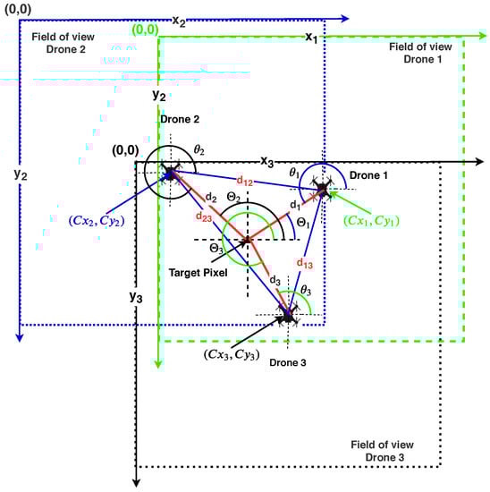
Figure 2.
Two-dimensional conceptual diagram for parameter measurements between the image centers of the target and the drones.
In image processing, pixel values are counted from the image’s top-left corner. For better clarity, the image width is represented as the X-axis, while the image height is shown as the Y-axis. In this case, we have three drones in a triangular configuration, and the target is within the formation. Colored dotted lines show individual drone fields of view. Individual drone distances to the target center are denoted as (, , and ) and individual drone distances as (, , and ). Objects outside the field of vision of an image are not tracked for RoI-based target selection. This paper provides a unique and straightforward computer vision-based localization and formation method for multiple aerial vehicles. Individual images provided by the different drones are examined. Multiple drones are located based on a common target-based localization method. For clarity, the notations used in this paper are defined in Table 2.
Table 2.
List of notations.
Figure 3 illustrates the complete system flow of object tracking based navigation system. The number of pixels required to cover a certain (1m) distance for a specific camera module is estimated prior to hardware implementation. The program adapts the pixel variable value based on the altitude calculated by the drone’s IMU. Images get represented in a two-dimensional coordinate method (X-axis and Y-axis) with the top left corner of the image denoted as image origin location. The angle from the image center to the target pixel is denoted as , the relative distance between individual drones is , and the image center is . An individual drone processes the data of images taken from a continuous sequence of the frames to store the parameter values in a comma-separated value file format.
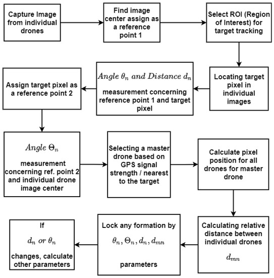
Figure 3.
Steps for estimating angle and distance parameters using a RoI-based object tracking approach.
The subsections that follow cover the target pixel extraction from the image in Section 3.1, and the estimation of angle and distance parameters from the acquired image in Section 3.2. Section 3.3 describes the interface between the image processing module and the flight controller.
3.1. Selection of RoI and Extraction of the Target Position Pixel with Frame Segmentation
The Region Of Interest (RoI) selected from the master drone becomes the template for other drones to track the same RoI in individual frames. The tracker then tracks that object inside a chosen area. For template matching in multiple drones, all drones are positioned in the same direction and closer to each other in order to follow the same target specified by RoI in master drone image. Selected RoI are captured and uploaded to the ground station; this template serves as the key matching region for subsequent drones to track the object. The embedded system determines the current position via interfaced sensors (HMC5883L and MPU 6050). If the position varies during real-time template matching, the drone notifies the user at the ground station to manually select RoI for that specific drone. For template matching, the individual frame gets converted into the grayscale for edge detection. Next, the edges of templates are compared in resized frame edges until the matching algorithm gives constant results, as shown in Figure 4. Individual drones in the drone formation are tracking the same target/object. If required, the algorithm can track separate objects beyond the formation employing individual drones. The method is intended to monitor an object in formation or to track and follow an individual object. Multiple RoI can be selected manually by the user in individual drones using a mouse click. This function adds the flexibility of target selection. If a drone loses sight of the target, the tracking area can be re-located using a template matching algorithm from the master or another drone’s tracking region template. If all of the drones lose sight of the target, the ground station is notified, and the user must select the RoI to track the target again. During the RoI selection process, all of the drones are oriented in the same direction to track the same item using a template matching algorithm.
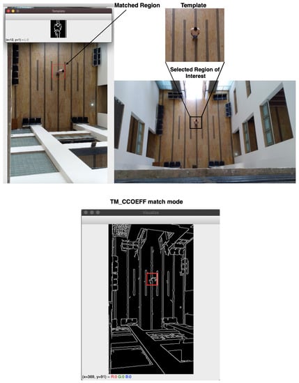
Figure 4.
RoI-based template extraction from a master drone image and matching—identifying the tracking region in another drone image heading in the same direction.
The center point detected from the detected area will be the target point center. The GPS sensor and first-person-view (FPV) camera are so arranged that the image center is the body frame center of the drone at that point of view. The RoI is chosen to form the image captured by individual drones. The image center is calculated from the image size as shown in Figure 5. A center of RoI gives the target pixel location within the image denoted as . The target pixel location can be anywhere in the image. To get the target pixel coordinates, the image is divided from the center. From image center to right-hand side axis starts from 0. This axis separates two regions (upper and lower half regions). The extended axis on the left side of the center point creates another two regions (upper and lower half regions). The image coordinate (x–y) values increase from the top left corner of the image. After segmentation, the target pixel is tracked from the image center. All the parameters (quadrant, angle, and distance) concerning the drone center are calculated based on the image center. This parameter varies as the target travels, resulting in a point-to-point calculation. The algorithm calculates the point-to-point movement based on the present co-ordinates and the change in the target observed by the algorithm.

Figure 5.
Image segmentation into four distinct quadrants for target localization.
The image segmentation is made in this work to identify the target position inside the image. The drone can steer or manoeuvre over the target depending on the target position. The image is split into four parts initially. The image is divided into four quadrants using the image center, which is measured by half of the image size (width and height). The quadrants will be chosen on the basis of the target pixel position in the image. Table 3 shows the calculations used to locate the object in the image (position of target pixel). The angle calculation varies as per the quadrants. Based on the target pixel coordinates (x–y), the target position in the quadrant is decided as shown in Table 3. The actual position of an object target center pixel position in the image can be in any of the four quadrants and as per the selected region of interest.
Table 3.
Position of target pixel.
3.2. Estimation of the Parameter Using Euclidean Quadratic Pixel Distance Measurement
To determine the angle and distance parameters, the target pixel position is first detected using the quadratic image segmentation method as explained in the previous subsection. The euclidean pixel distance between the image center and the target center can be calculated using the x and y position coordinates of both positions. is the target image pixel, whereas w and h are the width and height of the image respectively. The center pixel value of the image is () expressed as . To derive equations, we used Figure 5 as a reference. The hypotenuse distance is calculated by taking the square root difference between the respective and -axis squares shown in Equation (1). Adjacent can be estimated by taking the square root of the difference of the target axis value () and the image center -axis value (). Both -axis values are the same for the adjacent calculations, thus it will be neutralized (represented in Equation (2)). Similarly, the estimate for the opposite distance is given in Equation (3). The height parameter represented on the z-axis moreover the value of z is constant throughout the calculation. Distance and angle between the target pixel and image center is computed from cited equations.
where , and represent the hypotenuse, adjacent, and opposite, respectively, and n is the drone number. The equations are evaluated by identifying and testing different targets in the image and comparing them with the real-time parameters (distance and angle). The location is calculated based on the target center’s pixel location vis-a-vis the image center which is chosen as a reference. The actual error between the flight controller and the algorithm becomes zero. The actual distance is calculated based on the pixel counts between the reference and target point. Angle calculation based on Equations (1)–(3), are shown in Table 4. The mathematical operation performed in python (math library) are in radians. While programming, we need to convert radians to degree by multiplying with .
Table 4.
Angle calculations.
The drone height is fixed, and the number of pixels required to cover 1 m area is . The Euclidean distance between the two-pixel point is equivalent to the hypotenuse distance (calculated from Equation (1)) divided by . Depending on the position in a quadrant, the angle between the image center and target pixel is calculated. Suppose the target pixel lies in the third quadrant (), an angle is equal to + Positive angle correction constant ranging from 180 to 270 shown in Table 5.
Table 5.
Relation between image center and target pixel reference point.
Onboard continuous tracking and measurement algorithm registers the parameters. At a specific time instance, the master drone determines the relative distance and angle concerning individual drones. Such calculations are carried out concerning the image center (Reference point 1) of individual drones and then tracking object pixel as a reference (Reference point 2). This change in a reference point (1 to 2) from the image center to the object tracking pixel point is the change in relative angle. The angle ranges between 0 to 90 (Quadrant 1) from the image center to target pixel, the relative angle ranges between + 180. Similarly, the other angles range from 180 to 360.
Any of the drones from the formation can be a master drone because an individual drone has its distance and angle parameters and the other drone’s positions vis-a-vis the target position. Generally, a drone nearer to the target is chosen as the master. For this instance, drone 1 is the master, and pixel placements (or positions) of other drone locations are
where H is the actual distance calculated from (), and is the visual pixel location of the individual drones in the master drone image. Using Equation (4), individual drone centers can be visualized in master drone image. In the master drone image, the target position is . This is also true for other drones because we are locating the position of the other drones in the master drone image. If the modulus and negative target second axis position () are not used to calculate the , the second axis (image height) component may exceed the image limit, resulting in an inaccurate value for the other drone positions. The actual position of and are the same, but it is the pixel position for individual drones image and their respective position in the master drone image, respectively. Using the values of and , pixel coordinate values the relative distance between drones can be calculated. From a distance, one may fix the drone position or design a new drone formation by varying the parameter values of .
3.3. Interface between an Embedded Board and an Open-Source Flight Controller Unit
The actual body position/coordinates of a drone can be estimated after the target tracking and position estimation with the help of calculated parameters (, , , and ). The changes in the x and y positions of the drone body frame are calculated based on the target localization from the center of the image. This continuous variation in positions (due to target movement) is measured continuously by the embedded unit. With the help of the last known position and continuously measured values (, ), new calculated values of longitude and latitude are made available to the flight controller. As shown in interfacing Figure 6, first of all, drones hover at a height that is set initially during the programming (during testing, it ranges from ≈8 to 14 m). Now, in the second step, the embedded unit calculates the parameters. If any changes are measured (in case of target movement), new location coordinates get transferred to the flight controller; otherwise, it maintains the altitude and coordinates.
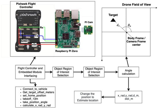
Figure 6.
Body frame position estimation.
The drones are embedded with Raspberry Pi 3 (with the PI camera) module. An open-source flight controller Pixhawk (PX4), powered by STM32F427 and STM32F100 ARM chipsets, is connected with four electronic speed controllers to control the quadcopters powered with 6000 mAh batteries. The camera unit is installed such that the center of gravity and the image center is the same. The flight controller unit is connected with a U-Blox 8 GPS unit with an independent compass unit for precise NMEA (National Marine Electronics Association) data. The telemetry module connects the UAVs (Unmanned Aerial Vehicles) and ground control stations. The radio transceiver module is connected to control UAV manually in an emergency. The accelerometer, compass, and radio are calibrated before the actual flight planning. The stabilization, auto, loiter, break, and smart return to launch modes are set in flight control mode. The raspberry pi embedded unit is connected to the flight controller through telemetry 1 port.
The embedded unit is integrated with MPU 6050 to measure orientation, relative velocity, and the HMC5883L magnetometer module to measure the direction and magnitude of the Earth’s magnetic field. Pi cam feeds the data to the embedded unit to process the data and measure the angle and distance. The resultant relative angle is calculated using image processing, and data are collected from the HMC5883L sensor unit. The drone setup is shown in Figure 7. All drones have identical flight controllers, embedded units, and camera setup hardware configurations. The individual drone equipped with the camera, embedded, and battery modules, weigh kg. Brushless DC (Direct Current) motors (920 KV) Counterclockwise (CCW) and Clockwise (CW) are coupled to self locking (9 inch) counter-rotating propellers. The motors are linked to the flight controller through a 30 A Electronic Speed Controller (ESC). The “X” configuration frame has strict magnetic compass locking calibration configurations. The frame size of the drone employed in our experiment is 45.5 cm (distance from opposite corner motors). The average flight time of the individual drone is about 13 to 16 min with 6000 mAh battery unit.

Figure 7.
Drone setup with a Pixhawk (PX4) flight controller in the center and an embedded unit and camera unit situated beneath the drones.
The proposed algorithm helps navigate the drone using the parameters from image sensors and geometry techniques. The target tracking-based method works flawlessly in real-time. The object should always be in the line of sight. If the target vision gets lost during the tracking, the drone stops following the predicted path. The drone increases its altitude by 5 m to get back to the target for tracking and keeps moving in the predicted path at the rate of 0.05 m/s for 10 s (0.5 m). If the target is still not visible, then the drone takes the operator’s help to select the RoI for tracking. By keeping the target near to image center, the algorithm tries to predict the target location based on target movement intensity in the 1 m pixel region in the image. A few microsecond delays can give the jerky motion to a drone. The drone has to transit smoothly, but the pixel change provides a more significant displacement if the camera unit drops any frames. For error minimization, the algorithm clears the cache memory by stopping data logging and transmitting the frame to the ground station until processing memory gets released. A sudden high wind may change the drone’s course during stable flight time. The drone tries to stabilize at a level position, and the algorithm helps to get back to the original position by measuring the target displacement concerning the image center. The entire process of drone acquired frame streaming, encryption–decryption, RoI selection, and identifying the object in other drones using template matching takes less than 5 s. If the tracking procedure is slow, it will not produce accurate results in real-time. We obtained precise results in real-time. We tested the system indoors, where GPS signals are unavailable, and outside, in windy conditions with high-rise buildings and trees in the surrounding region.
4. Results and Analysis
Images captured by individual drones are analyzed in this section, and parameters for the same are estimated. During testing, we attempted to keep all of the drones at the same altitude, but to compensate for environmental effects, the drones attempted to modify their altitude. Furthermore, if the individual drones are less than 0.5 m apart, the height of the drones is changed to avoid collisions. The next subsection explains parameter computations.
4.1. Distance and Angle Parameters Measurement over Collected Frames
The onboard embedded unit processes the frames gathered by the camera unit in real-time. Individual drone images are examined and calculations are conducted. The results given here are the preprocessed images produced by the Raspberry Pi 3B module. The higher resolution frames are taken by the Pi Zero camera, and the images are scaled to pixel resolution for efficient processing. The images illustrate the results of the processed frame’s angle and distance computations. We extracted screenshots from the continuous processing frames given as results and labeled them with a color text box to better understand the process. The image taken by drone 1 including measured angle and distance is shown in Figure 8. (, ) is the image center of drone 1, is distance between center of image to the selected object (, ). Similarly, (, ) and (, ) are image centers for drones 2 and 3 as shown in Figure 9 and Figure 10. The quadratic position of the target is visualized in Figure 8 with a blue font. The measured angle is denoted by the letters “agl” in green typefaces. Green circular dots represent the crossover points of the hypotenuse, neighboring, and opposite Equations (1)–(3). In the images, the target is depicted as a square cross-section in Figure 8, Figure 9 and Figure 10.
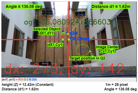
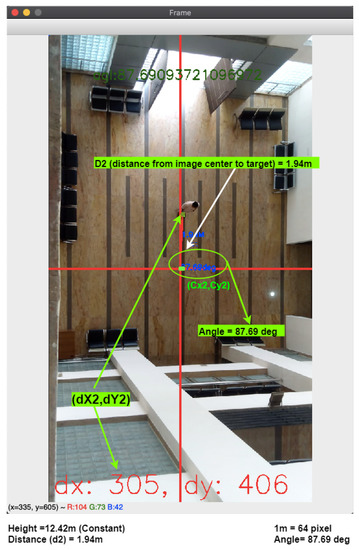
Figure 9.
Parameter estimation and target localization in drone 2 image.
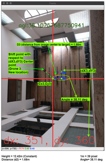
Figure 10.
Parameter estimation and target localization in drone 3 image.
The outcomes of the calculation are elaborated in Table 6. The processed individual drone images are listed in the first column of Table 6, as indicated in the () column target location in the image quadrant. The first parameter, target angle concerning image center, is computed and shown in the column. Next, the distance is determined using the number of pixels required to cover the 1 m distance calculated during camera calibration.
Table 6.
Scenario based measurement.
The relative angles from reference point 2 (i.e., target pixel) to the image center are calculated and illustrated in Table 7. Drone 1 is the master drone, and so the reference point 2 location is = (273, 142). The values of are calculated using Equation (4), and are the pixel location of drones other than the master drone. The value of is calculated by (). We choose for the measurements in the master drone 1 image. The calculated location can be seen in Figure 11.
Table 7.
Localization of drones 2 and 3 in master drone image.
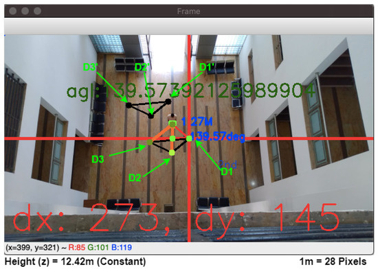
Figure 11.
Individual drone positions in master drone image calculated using Equation (4); initial triangle arrangement visualized as individual drones D1, D2, and D3. D1, D2, and D3 triangular formation is the new estimated position as the master drone changes its position from D1 to D1.
Points D2 and D3 are Drones 2 and 3 image centers in Figure 11. The relative distance between drones is locked such that if one drone moves in certain direction, the master drone calculates the new positions. Drone 3 (D3) moves from i.e., (236, 171) to i.e., (202, 114) location. The difference is , which is directly added to the all drone pixel location in master drone. The resultant formation can be seen in Figure 11 denoted as D1, D2, and D3.
In Figure 12, the object tracking with an estimated individual drone position is calculated by an on-board computer. With a fixed drone position, the estimated target position gets calculated continuously and stored in a buffer. The visual representation of buffer value is visible as a target red-colored track line. The black triangle is the drone’s fixed formation which changes as the target moves. The drones’ group position is fixed in this calculation, but the target position varies. The triangle is the estimated position for each drone, not the current position. For precision localization and navigation, we need a centimeter-level precise GPS module. For the formation shown in Figure 12, the gathered GPS values are almost identical for individual drones because the formation is close (<2 m) to each other. The tracking position is calculated with respect to master drone image center, and so the image center remains fixed during testing. The tracking results are presented in Figure 12 come from reference image, which is why the image’s center position remains steady throughout the tracking process. The target trajectory cannot be perceived accurately if the tracking computation is shown in each individual drone image.
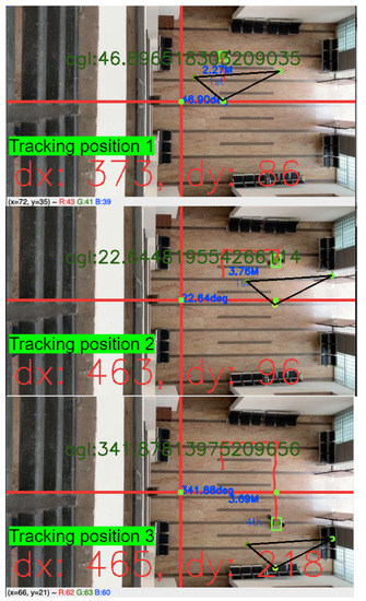
Figure 12.
Tracking of moving object and position estimation (Positions 1, 2, and 3).
The GPS coordinates are measured herewith, but within the 10 m to 15 m range, the change in the coordinates is in (1-s change). For precision, the distance should be within the 1 m range (GPS coordinates are measured with Trimble Juno 3B equipment). Table 8 shows the measured value for this calculation. The accuracy between the natural and computer vision-based measured value is . This error is generated because the captured image tilted while capturing the image, which creates the angle between the horizontal plane. The image captured from FPV (First-person View) camera has radial distortions (positive or negative radial distortions). This error gets minimized with the help of gimbal support, calibration, and by keeping the target nearer to the image center. From the practical implementations, we find that the target near the image center has lower errors.
Table 8.
Target position measurements and comparison with actual values.
The raspberry pi establishes the serial connection with the flight controller through the telemetry port. After connection establishment, an embedded system checks the pre-set parameters like arm check, arm throttle check, and selecting flight mode. By default, the system sets flight mode to stabilized mode and gives to arm command to take off. In the auto mode, movement takes place alongside the target and formation at a fixed distance and angle, and the flight controller takes the target point as a fixed waypoint. Finally, the throttle value gets set for exact distance and angle values. This embedded system calculates other parameters such as roll, pitch, and angle to move along with the target, and the initial stage formation is shown in Figure 13.
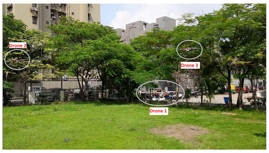
Figure 13.
Drone initial formation during the field test.
The setup is tested in the open ground field to avoid collisions in an indoor environment. The live feed is seen through the wireless local area network even as all drones connect to the local network. Figure 14A,B shows the results of image encryption and decryption, respectively. Figure 14B shows the first person view with a selected region of interest from the drone.
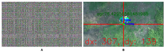
Figure 14.
Results of image encryption (A) and decryption (B).
The target is located at , that is, from North, at m distance from image center (height m). The target at the image border has some errors due to radial distortions while using the wide-angle lens camera for object tracking. Such errors are reducible through camera calibration by measuring the same object size in different pixel locations in the same image. However, it is challenging to measure object size from the various pixel locations, and so the only solution is to keep the object nearer to the image center. The drone height varies at the time of stabilization to counter external environmental changes. If the drone height decreases, the target will move towards the image edge, increasing the distance measurement error. The drone strives to set the position to keep the target towards the center of the image, reducing the maximum error of to . With the drone not moving along the target, and the object at the image’s edge, the distance error ranges from to m. Therefore, the algorithm tries to keep the object near the center to neutralize this error, and we get accurate position coordinates shown in Figure 14 with zero error. We tested the algorithm on two distinct heights (≈12 and 9 m) and obtained accurate results for both. Drone formations adjust their altitude to adapt for environmental effects and to keep the formation stable. Figure 8, Figure 9 and Figure 10 and Figure 14 present the results obtained at these heights. The on-board integrated unit required a maximum of 520 mAh to capture and process the frames. Our quadcopter’s normal flight time is between 13 and 16 min. By incorporating the embedded system, the flight duration will be reduced by approximately 1 m. The ground station monitors and controls every drone path; in our case, we employed the ground station for target selection, data logging, and providing extra object detection information to the operator. Therefore, the DGPS-based drones should be constantly connected to the ground stations, as it is entirely dependent on the fixed hardware at the ground station in an unobstructed range region. In our technique, after selecting RoI from the ground station laptop (which is initially dependent on the ground station), the drone navigates itself without the assistance of the ground station until the target is out of sight in all of the drones. As a result, the proposed method provides a standalone solution for tracking an object that does not require any additional hardware, such as a differential global positioning system (DGPS).
Figure 15 shows the flight log of individual drones. The flight path of the master drone (drone 1) is the longest among all the drone paths as it tries to keep the target nearer to the image center and tracks it for a long duration compared to the other drones. Drones 2 and 3 land sequentially, and the master drone lands after the touchdown by other drones is confirmed. The take off position of the master drone is nearer to the target to start synchronizing the signals to other drones. The image visualization happens by logging the data on the flight controller and with the help of the Google Earth application. Individual drones attempt to maintain the predetermined configuration (here linear fashion). Drone 1 is the first to take off, followed by Drone 2 from an immediate vicinity, and Drone 3 in the middle of the tracking shown in Figure 16.
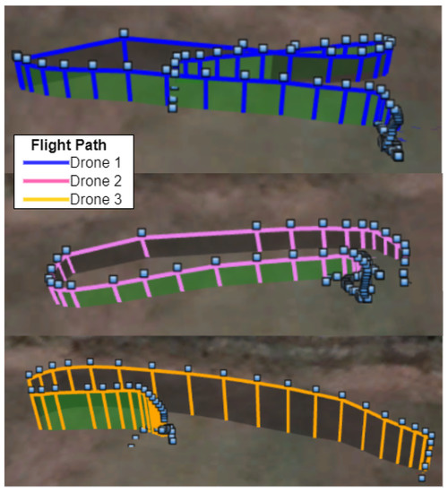
Figure 15.
Individual drone flight paths were logged during the test flight and depicted using the Google Earth application.
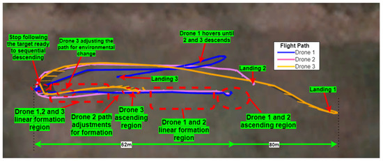
Figure 16.
Top view of flight path.
Drones 1 and 2 take off first and second, respectively, and fly in a linear formation following the shared RoI target. Because the target does not have a GPS position logging device, the target’s trajectory is not evident. Drone 2 adjusts its direction as drone 3 joins the formation, making the three-drone position linear. Drone 3 adjusts the path and formation by altering the angle and distance parameters while tracking to accommodate environmental changes (sudden wind flow from North–West to South–East). Drones are landed on a pre-defined path when they have stopped following the target (location set before the drone ascending). The flight that takes off last is the first to land, and all consecutive drones follow such rules. The master drone 1 lands after the successful landing of individual drones. As it is easier to track a new target by an air drone throughout the landing procedure, the master drone hovers until the other drones land. The formation’s total distance spanned is ≈62 m. If the target does not move, the quadcopter will retain its position. The technique can be further customized for fixed-wing aircraft by modifying the flight dynamics to hover in a circular route over the target.
Further, the drone can track another drone during the in-air flight and makes moves according to the target movement with the help of the vertically positioned FPV camera. This process measures the relative angle to the image center and positive angle correction during flight time. Due to no reference in AOT (Airborne Object Target Tracking), RoI-based target tracking helps navigate the drone. The algorithm tracks the other drones by measuring angular displacement to the master drone image. The drone tracking algorithm is still in the initial phase of testing, as shown in Figure 17 which shows red track lines for the registered drone positions. The algorithm identifies the angle accurately, although the drone movements are quick inside the image. While chasing the drone, if the target is nearer to the image center. During testing, the second flight is stable at ≈ 6 to m height. The subplots A to I of Figure 17 show the drone tracking results from different angles and positions. During this test, the embedded unit controls the yaw and pitch without change in the original position. The drone tracking algorithm is still in an initial phase. An extension of this work would involve following the target with a collision control algorithm using computer vision and other sensors.
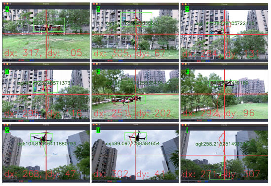
Figure 17.
Airborne Object target Tracking (AOT) (drone to drone tracking).
The proposed method processes the captured frame () at 26 to fps on a low specification embedded board (Raspberry Pi 3 module). We can implement this method on new and updated boards like Nvidia Jetson TX and Xavier series for higher processing capacity. The target tracking by the embedded unit in our approach process frames faster compared to the method proposed by [12,31] (TX2 platform) by 60 and in terms of tracking efficiency. The applications and methods provided in the referred articles are different, but we make the comparison as far as tracking efficiency and processing speed are concerned. A detailed comparison is provided in the next subsection.
4.2. Comparison of Proposed Method to State-of-the-Art Methods
The experimental results by Mi et al. [35] on camera images achieved fps speed of processing at over resolution video using GHz CPU and 16 GB RAM. Our approach used a GHz CPU with 1 GB RAM and achieved accuracy with the same CSRT (Channel and Spatial Reliability Tracker) tracking method and the result is accurate on a low specification embedded unit, proving that CSRT tracker-based object tracking and navigation method comes with higher accuracy and needs low operating power.
Recker et al. [31] proposed a precision landing method based on target identification and position estimation in which the object detection neural network provides the bounding box to the photogrammetry target tracking algorithm to find the target (bar code) center. Chen et al. [12] proposed a method to track objects (human in an experiment) from a vertical-facing camera using an object detection algorithm. Mi et al. compared different target tracking methods using a camera and concluded that the CSRT tracking method has higher accuracy compared to others.
Chen et al. proposed an object detection-based target tracking technique which achieve the desired goal in three different stages: (i) An Oriented FAST and Rotated Binary robust independent elementary technique (ORB) for feature extraction, (ii) a local difference binary (LDB) to get binary descriptors, and (iii) K-Nearest Neighbor (KNN) to find a match of image descriptors. Recker et al. used object detection method for target identification and tracking using DetectNet consisting of a fully convolution neural network. In both techniques, the object detection method helps identify/track the target. However, the object detection method has a common problem of processing delay dependent upon the algorithm’s accuracy. Therefore, either the detection algorithm gives accuracy or speed, and the solution towards balancing the accuracy and speed limits the algorithm adaptively. Furthermore, an object tracking algorithm trained to track the specific object using neural network weights tuned for that particular object size, color, orientation, and camera settings, limits the implementation in real-life tracking conditions. However, in our approach, we tested different tracking algorithms for drone navigation, free from target size, shape, color, and orientation due to RoI-based target selection. Moreover, the proposed algorithm only utilizes 80 to 110 MiB (Mebibyte) (≈0.084 to GB, where 1 MiB GB), which is lower than the physical hardware memory ( MiB = 1 GB). Memory optimization is required because apart from calculating the processor, the processor needs to also transfer the processed frame to the ground station after image encoding for data security.
The proposed method tracks, estimates, and analyzes the position accuracy of different objects captured from the frame. Further, we have introduced selection-based target tracking, which is missing in the available literature. The CSRT provides a higher accuracy during the parameter calculation in our tracking algorithm that is similar to the conclusion made by Mi et al. in camera-based target tracking. The CSRT tracker has higher accuracy compared to KCF (Kernelized Correlation Filters), TLD (Tracking, learning, and detection), Medianflow, and Mosse (Minimum Output Sum of Squared Error) tracking methods. The accuracy of different tracking methods is observable from Figure 18.
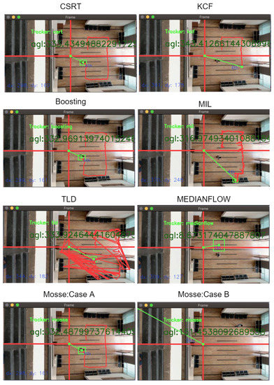
Figure 18.
Comparison of tracking methods.
Techniques like KCF, MIL (Multiple Instance Learning), TLD, and Medianflow tracker lose the target while performing position tracking. Additionally, the Mosse tracking algorithm provides inconsistent accuracy during testing. The target RoI are shown as cases A and B in Figure 18 for Mosse algorithm. If the target and background are distinguishable and the target size exceeds 660-pixel density (), the Mosse tracker gives an accurate result at a higher frame processing rate (≈40 fps). As the target is distinguishable, it provides the precise result as CSRT tracker shown as Mosse: case A in Figure 18. During selection of RoI from different locations, Mosse tracker fails shown as case B. CSRT gives accurate results in all conditions at the rate up to ≈29 fps. The above results are calculated based on the CSRT tracking method. The Boosting tracker is faster than CSRT but not so accurate when the object/target overlaps and is out of the vision for some instance. The CSRT and Mosse tracker (for the large object) is suitable for object tracking-based navigation methods compared to other methods. Compared to other navigation methods that rely on GPS sensors to provide accurate location of the drones, computer vision is required to do specific tasks such as moving along with the target, surveillance, and formation. However, computer vision-based tracking costs are low (less than 80 USD) compared to other navigation technologies such as DGPS, LiDAR (average cost of planar LiDAR is 250 USD), or SLAM-based techniques. Furthermore, the positioning inaccuracy of our approach is less than 50 cm. It will achieve centimeter-level accuracy after progressing and moving the target closer to the image center and may be utilized for target surveillance, tracking, and following. The time to achieve centimeter-level precision is only a few seconds because the drone tries to set the target closer to the image center at a ground speed of to m per s. As illustrated in Figure 14B, the suggested technique achieves precise ( accurate) centimeter-level accuracy in target position estimation.
5. Conclusions and Future Work
This proposed method provides solutions for drone formation and precision movement in GPS-denied regions with target tracking. Furthermore, the target coordinates (angle, distance from drone position) are estimated concerning drone position obtained from the ground station. RoI-based target selection is free from the fixed color, shape, or pattern-based target tracking. Moreover, the proposed method can track multiple targets in a single image in individual drones. The different techniques of object tracking are compared for this navigation application. It is concluded that CSRT-based tracking methods can be implemented for drone navigation having a down-facing camera. Multiple drones can track and follow individual targets if formation is not necessary. The proposed navigation is processed (29 fps) in real-time without delay and stored processed information to the remote server after encryption. We were able to achieve a significant flight time of up to 13 to 14 min using a 6000 mAh battery (about kg drone weight) and the image processing unit to process real-time frames. In comparison to civilian GPS sensors which have an accuracy of 3 m radius, the suggested approach provides very accurate (up to ) angle and distance measurements with respect to drone’s original location. The proposed image processing based drone navigation method can play a crucial role in multi-angle view cinematography. In low visibility, a thermal camera can replace the primary camera without modification in the algorithm. The algorithm also tracks and locates aerial objects (drone to drone in our case) and maybe a useful counter-drone technology to track an aerial object before taking necessary action. In the future, the analysis of the time to reach the estimated and current position and the position estimation in case of a lost target are crucial tasks.
Author Contributions
Problem identification and conceptualization, J.U., D.D. and A.R; data collection and algorithm optimization, J.U.; critical analysis of output, D.D. and A.R.; writing—original draft, J.U. and D.D.; writing—review and editing, D.D. and A.R. All authors have read and agreed to the published version of the manuscript.
Funding
This research received no external funding.
Institutional Review Board Statement
None.
Informed Consent Statement
None.
Data Availability Statement
None.
Conflicts of Interest
The authors declare no conflict of interest.
References
- Kanellakis, C.; Nikolakopoulos, G. Survey on Computer Vision for UAVs: Current Developments and Trends. J. Intell. Robot. Syst. 2017, 87, 141–168. [Google Scholar] [CrossRef] [Green Version]
- Artieda, J.; Sebastian, J.M.; Campoy, P.; Correa, J.F.; Mondragón, I.F.; Martínez, C.; Olivares, M. Visual 3-D SLAM from UAVs. J. Intell. Robot. Syst. 2009, 55, 299–321. [Google Scholar] [CrossRef]
- Faessler, M.; Fontana, F.; Forster, C.; Mueggler, E.; Pizzoli, M.; Scaramuzza, D. Autonomous, Vision-based Flight and Live Dense 3D Mapping with a Quadrotor Micro Aerial Vehicle. J. Field Robot. 2015, 33, 431–450. [Google Scholar] [CrossRef]
- Deb, D.; Rawat, A.; Upadhyay, J. WLAN-Based Smart Door Closer Design with Image Classification. In Recent Trends in Peripheral Security Systems; Springer: Singapore, 2021; pp. 43–70. [Google Scholar] [CrossRef]
- Upadhyay, J.; Rawat, A.; Deb, D.; Muresan, V.; Unguresan, M.L. An RSSI-Based Localization, Path Planning and Computer Vision-Based Decision Making Robotic System. Electronics 2020, 9, 1326. [Google Scholar] [CrossRef]
- Rawat, A.; Deb, D.; Upadhyay, J. Robotic System Configuration with Localization, Path Planning, and Computer Vision. In Recent Trends in Peripheral Security Systems; Springer: Singapore, 2021; pp. 71–95. [Google Scholar] [CrossRef]
- Yoo, C.S.; Ahn, I.K. Low cost GPS/INS sensor fusion system for UAV navigation. In Proceedings of the 22nd Digital Avionics Systems Conference Proceedings (Cat No 03CH37449), Indianapolis, IN, USA, 12–16 October 2003. [Google Scholar] [CrossRef]
- Beard, R.; Kingston, D.; Quigley, M.; Snyder, D.; Christiansen, R.; Johnson, W.; McLain, T.; Goodrich, M. Autonomous Vehicle Technologies for Small Fixed-Wing UAVs. J. Aerosp. Comput. Inf. Commun. 2005, 2, 92–108. [Google Scholar] [CrossRef] [Green Version]
- Kim, Y.; Jung, W.; Bang, H. Visual Target Tracking and Relative Navigation for Unmanned Aerial Vehicles in a GPS-Denied Environment. Int. J. Aeronaut. Space Sci. 2014, 15, 258–266. [Google Scholar] [CrossRef]
- Zhao, S.; Hu, Z.; Yin, M.; Ang, K.Z.Y.; Liu, P.; Wang, F.; Dong, X.; Lin, F.; Chen, B.M.; Lee, T.H. A Robust Real-Time Vision System for Autonomous Cargo Transfer by an Unmanned Helicopter. IEEE Trans. Ind. Electron. 2015, 62, 1210–1219. [Google Scholar] [CrossRef]
- Koubaa, A.; Qureshi, B. DroneTrack: Cloud-Based Real-Time Object Tracking Using Unmanned Aerial Vehicles Over the Internet. IEEE Access 2018, 6, 13810–13824. [Google Scholar] [CrossRef]
- Chen, P.; Dang, Y.; Liang, R.; Zhu, W.; He, X. Real-Time Object Tracking on a Drone With Multi-Inertial Sensing Data. IEEE Trans. Intell. Transp. Syst. 2018, 19, 131–139. [Google Scholar] [CrossRef]
- Wing, M.G.; Eklund, A.; Kellogg, L.D. Consumer-Grade Global Positioning System (GPS) Accuracy and Reliability. J. For. 2005, 103, 169–173. [Google Scholar] [CrossRef]
- Taha, B.; Shoufan, A. Machine Learning-Based Drone Detection and Classification: State-of-the-Art in Research. IEEE Access 2019, 7, 138669–138682. [Google Scholar] [CrossRef]
- Cichella, V.; Kaminer, I.; Dobrokhodov, V.; Hovakimyan, N. Coordinated vision-based tracking for multiple UAVs. In Proceedings of the 2015 IEEE/RSJ International Conference on Intelligent Robots and Systems (IROS), Hamburg, Germany, 28 September– 2 October 2015. [Google Scholar] [CrossRef]
- Lin, S.; Garratt, M.A.; Lambert, A.J. Monocular vision-based real-time target recognition and tracking for autonomously landing an UAV in a cluttered shipboard environment. Auton. Robot. 2016, 41, 881–901. [Google Scholar] [CrossRef]
- Fu, C.; Duan, R.; Kircali, D.; Kayacan, E. Onboard Robust Visual Tracking for UAVs Using a Reliable Global-Local Object Model. Sensors 2016, 16, 1406. [Google Scholar] [CrossRef] [PubMed] [Green Version]
- Yang, X.; Chen, J.; Dang, Y.; Luo, H.; Tang, Y.; Liao, C.; Chen, P.; Cheng, K.T. Fast Depth Prediction and Obstacle Avoidance on a Monocular Drone Using Probabilistic Convolutional Neural Network. IEEE Trans. Intell. Transp. Syst. 2019, 22, 156–167. [Google Scholar] [CrossRef]
- Rozantsev, A.; Lepetit, V.; Fua, P. Detecting Flying Objects Using a Single Moving Camera. IEEE Trans. Pattern Anal. Mach. Intell. 2017, 39, 879–892. [Google Scholar] [CrossRef] [PubMed]
- Schilling, F.; Lecoeur, J.; Schiano, F.; Floreano, D. Learning Vision-Based Flight in Drone Swarms by Imitation. IEEE Robot. Autom. Lett. 2019, 4, 4523–4530. [Google Scholar] [CrossRef] [Green Version]
- Abughalieh, K.M.; Sababha, B.H.; Rawashdeh, N.A. A video-based object detection and tracking system for weight sensitive UAVs. Multimed. Tools Appl. 2018, 78, 9149–9167. [Google Scholar] [CrossRef]
- Wang, Z.; Liu, D.; Lei, Y.; Niu, X.; Wang, S.; Shi, L. Small target detection based on bird’s visual information processing mechanism. Multimed. Tools Appl. 2020, 79, 22083–22105. [Google Scholar] [CrossRef]
- Nguyen, H.D.; Na, I.S.; Kim, S.H.; Lee, G.S.; Yang, H.J.; Choi, J.H. Multiple human tracking in drone image. Multimed. Tools Appl. 2018, 78, 4563–4577. [Google Scholar] [CrossRef]
- Hossain, S.; Lee, D.J. Deep Learning-Based Real-Time Multiple-Object Detection and Tracking from Aerial Imagery via a Flying Robot with GPU-Based Embedded Devices. Sensors 2019, 19, 3371. [Google Scholar] [CrossRef] [Green Version]
- Choi, K.; Oh, B.S.; Yu, S. Memory access minimization for mean-shift tracking in mobile devices. Multimed. Tools Appl. 2020. [Google Scholar] [CrossRef]
- Zhang, H.; Wang, G.; Lei, Z.; Hwang, J.N. Eye in the Sky. In Proceedings of the 27th ACM International Conference on Multimedia, Nice, France, 21–25 October 2019. [Google Scholar] [CrossRef] [Green Version]
- Jung, S.; Hwang, S.; Shin, H.; Shim, D.H. Perception, Guidance, and Navigation for Indoor Autonomous Drone Racing Using Deep Learning. IEEE Robot. Autom. Lett. 2018, 3, 2539–2544. [Google Scholar] [CrossRef]
- Zhou, J. EKF based object detect and tracking for UAV by using visual-attention-model. In Proceedings of the 2014 IEEE International Conference on Progress in Informatics and Computing, Shanghai, China, 16–18 May 2014. [Google Scholar] [CrossRef]
- Suh, M.S.; Nam, C. A study on operational ability comparing drone-centric and user-centric control in external piloting. Multimed. Tools Appl. 2020, 79, 24265–24279. [Google Scholar] [CrossRef]
- Edwards, B.; Archibald, J.; Fife, W.; Lee, D.J. A Vision System for Precision MAV Targeted Landing. In Proceedings of the 2007 International Symposium on Computational Intelligence in Robotics and Automation, Jacksonville, FL, USA, 20–23 June 2007. [Google Scholar] [CrossRef]
- Recker, S.; Gribble, C.; Butkiewicz, M. Autonomous Precision Landing for the Joint Tactical Aerial Resupply Vehicle. In Proceedings of the 2018 IEEE Applied Imagery Pattern Recognition Workshop (AIPR), Washington, DC, USA, 9–11 October 2018. [Google Scholar] [CrossRef]
- Truong, N.Q.; Nguyen, P.H.; Nam, S.H.; Park, K.R. Deep Learning-Based Super-Resolution Reconstruction and Marker Detection for Drone Landing. IEEE Access 2019, 7, 61639–61655. [Google Scholar] [CrossRef]
- Eckert, J.; German, R.; Dressler, F. An Indoor Localization Framework for Four-Rotor Flying Robots Using Low-Power Sensor Nodes. IEEE Trans. Instrum. Meas. 2011, 60, 336–344. [Google Scholar] [CrossRef] [Green Version]
- Upadhyay, J.; Deb, D.; Rawat, A. Design of Smart Door Closer System with Image Classification over WLAN. Wirel. Pers. Commun. 2019, 111, 1941–1953. [Google Scholar] [CrossRef]
- Mi, T.W.; Yang, M.T. Comparison of Tracking Techniques on 360-Degree Videos. Appl. Sci. 2019, 9, 3336. [Google Scholar] [CrossRef] [Green Version]
- Lukežič, A.; Vojíř, T.; Zajc, L.Č.; Matas, J.; Kristan, M. Discriminative Correlation Filter Tracker with Channel and Spatial Reliability. Int. J. Comp. Vis. 2018, 126, 671–688. [Google Scholar] [CrossRef] [Green Version]
- Urzua, S.; Munguía, R.; Grau, A. Vision-based SLAM system for MAVs in GPS-denied environments. Int. J. Micro Air Veh. 2017, 9, 283–296. [Google Scholar] [CrossRef]
- Urzua, S.; Munguía, R.; Nuño, E.; Grau, A. Minimalistic approach for monocular SLAM system applied to micro aerial vehicles in GPS-denied environments. Trans. Inst. Meas. Control 2018, 40, 4345–4357. [Google Scholar] [CrossRef]
- Trujillo, J.C.; Munguia, R.; Guerra, E.; Grau, A. Cooperative Monocular-Based SLAM for Multi-UAV Systems in GPS-Denied Environments. Sensors 2018, 18, 1351. [Google Scholar] [CrossRef] [PubMed] [Green Version]
- Dayangac, E.; Baumann, F.; Aulinas, J.; Zobel, M. Target Position and Speed Estimation Using LiDAR. In Lecture Notes in Computer Science; Springer International Publishing: Cham, Switzerland, 2016; pp. 470–477. [Google Scholar]
- Wandinger, U. Introduction to Lidar. In Lidar; Springer: New York, NY, USA, 2005; pp. 1–18. [Google Scholar]
- Hamzah, R.A.; Ibrahim, H. Literature Survey on Stereo Vision Disparity Map Algorithms. J. Sens. 2016, 2016, 8742920. [Google Scholar] [CrossRef] [Green Version]
- Hansard, M.; Lee, S.; Choi, O.; Horaud, R. Time-of-Flight Cameras; Springer: London, UK, 2013. [Google Scholar]
- Loukhaoukha, K.; Chouinard, J.Y.; Berdai, A. A Secure Image Encryption Algorithm Based on Rubik’s Cube Principle. J. Electr. Comput. Eng. 2012, 2012, 173931. [Google Scholar] [CrossRef] [Green Version]
Publisher’s Note: MDPI stays neutral with regard to jurisdictional claims in published maps and institutional affiliations. |
© 2021 by the authors. Licensee MDPI, Basel, Switzerland. This article is an open access article distributed under the terms and conditions of the Creative Commons Attribution (CC BY) license (https://creativecommons.org/licenses/by/4.0/).