
Filter Extracted Sliding Mode Approach for DC Microgrids


Abstract
:1. Introduction
2. Control Architectures
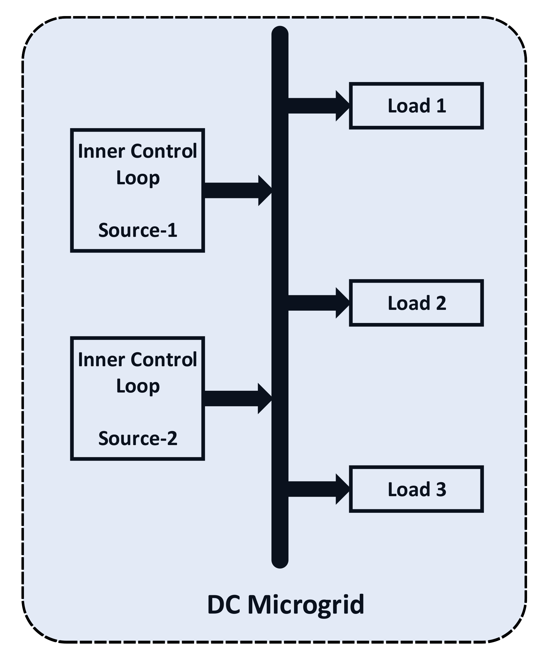
2.1. Decentralized Control
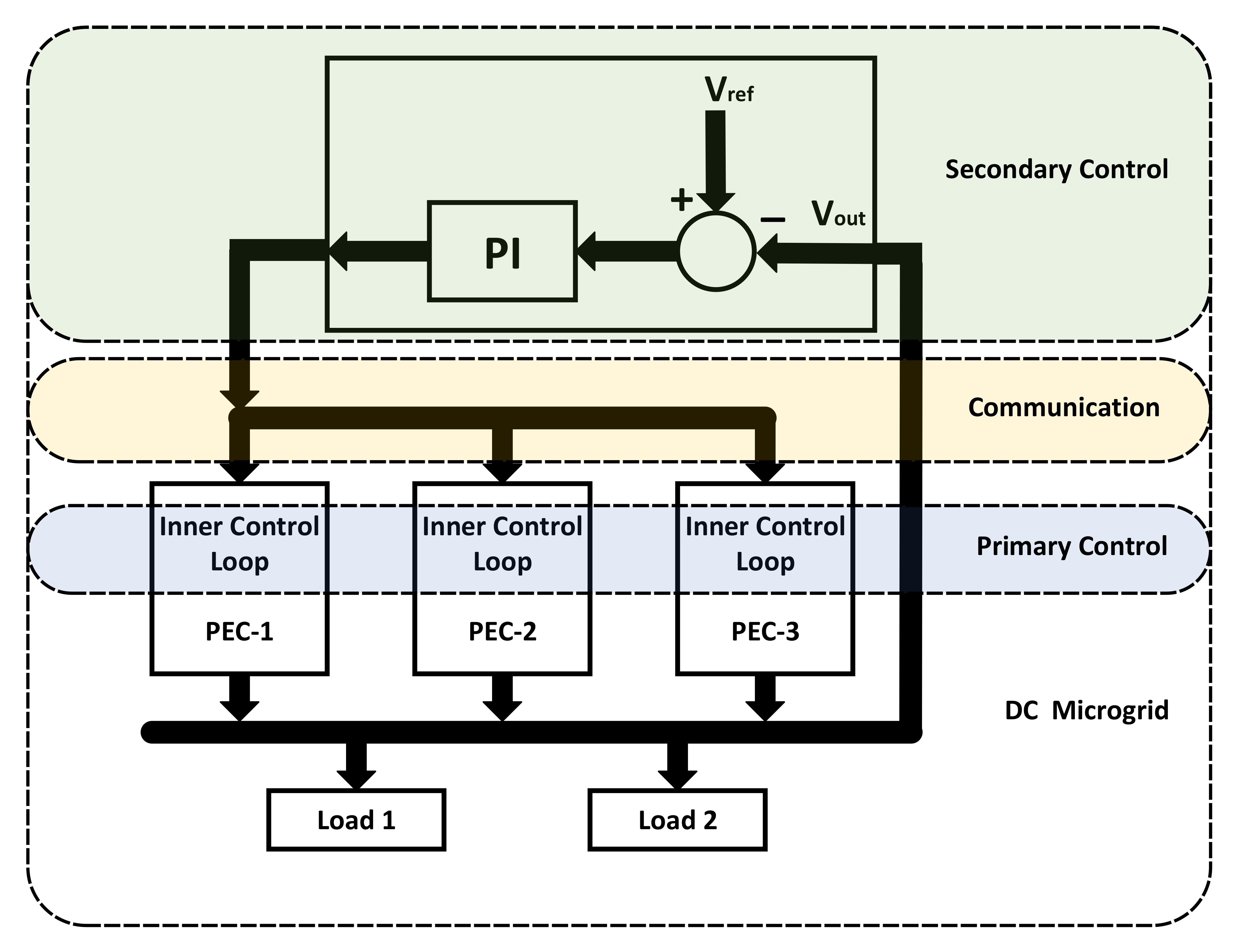
2.2. Centralized Control
3. Proposed Controller
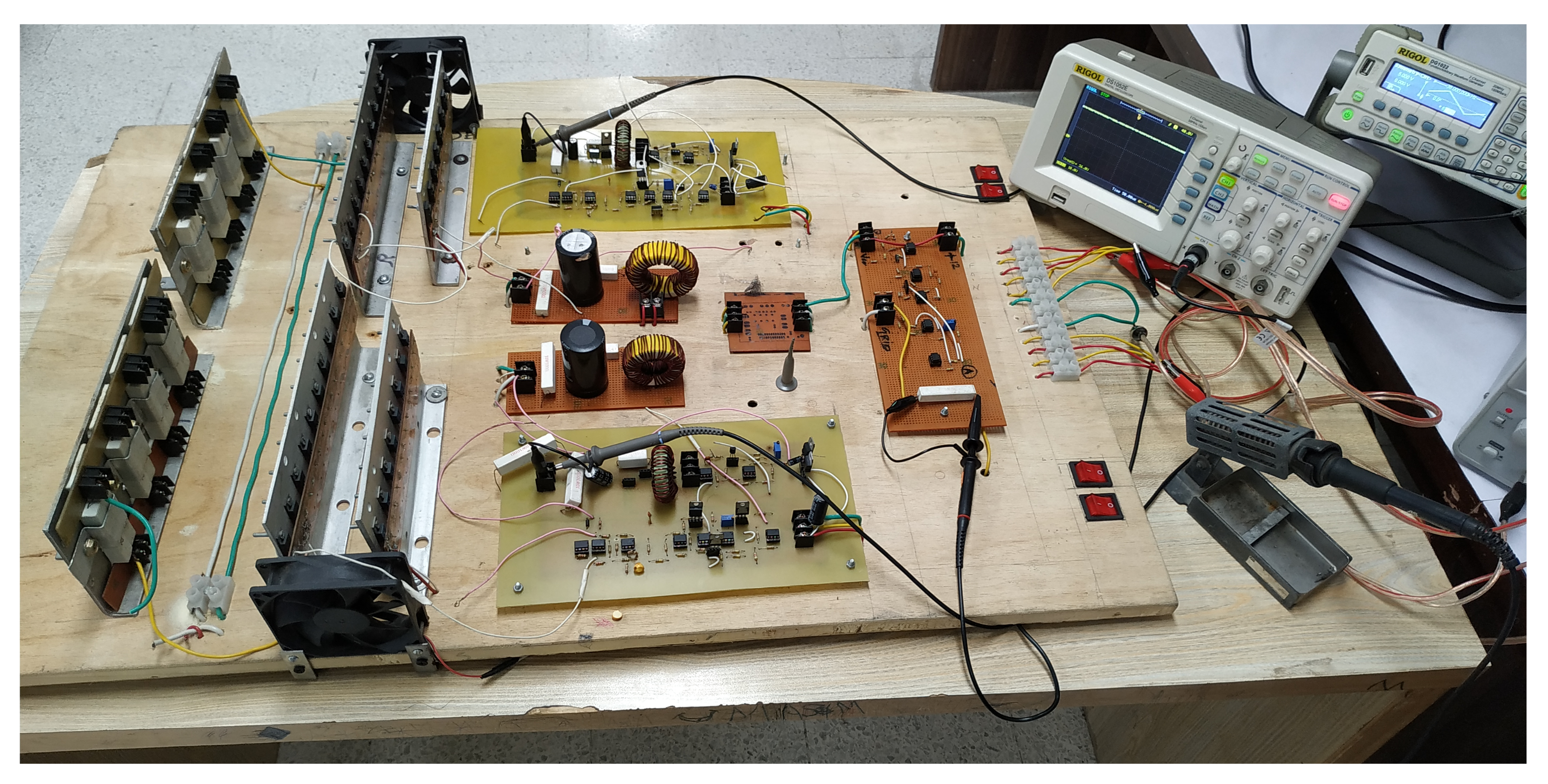
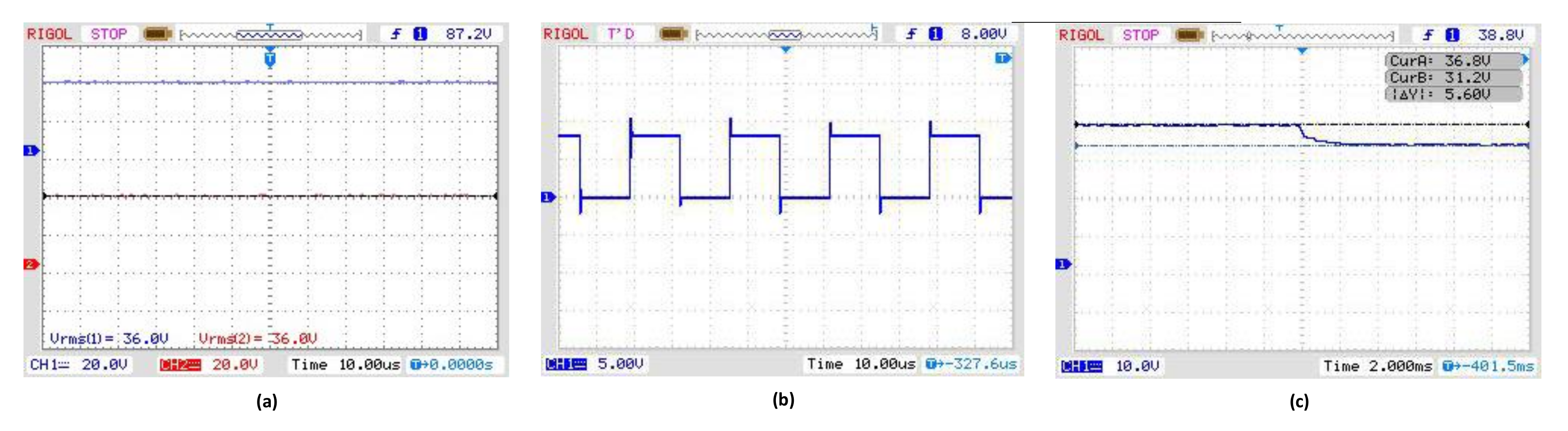
4. Results and Discussion
5. Conclusions
Author Contributions
Funding
Conflicts of Interest
References
- Akeyo, O.M.; Patrick, A.; Ionel, D.M. Study of Renewable Energy Penetration on a Benchmark Generation and Transmission System. Energies 2021, 14, 169. [Google Scholar] [CrossRef]
- Ahmed, D.; Ebeed, M.; Ali, A.; Alghamdi, A.S.; Kamel, S. Multi-objective energy management of a micro-grid considering stochastic nature of load and renewable energy resources. Electronics 2021, 10, 403. [Google Scholar] [CrossRef]
- Ma, J.; Zhang, S.; Li, X.; Du, D. Integrating base-load cycling capacity margin in generation capacity planning of power systems with high share of renewables. Trans. Inst. Meas. Control. 2019, 42, 31–41. [Google Scholar] [CrossRef]
- Anand, S.; Fernandes, B. Optimal voltage level for DC microgrids. In Proceedings of the IECON 2010—36th Annual Conference on IEEE Industrial Electronics Society, Glendale, AZ, USA, 7–10 November 2010; pp. 3034–3039. [Google Scholar]
- Affam, A.; Buswig, Y.M.; Othman, A.K.B.H.; Julai, N.B.; Qays, O. A review of multiple input DC-DC converter topologies linked with hybrid electric vehicles and renewable energy systems. Renew. Sustain. Energy Rev. 2021, 135, 110186. [Google Scholar] [CrossRef]
- Ghorbal, M.J.B.; Moussa, S.; Ziani, J.A.; Slama-Belkhodja, I. A comparison study of two DC microgrid controls for a fast and stable DC bus voltage. Math. Comput. Simul. 2021, 184, 210–224. [Google Scholar] [CrossRef]
- Esmaeli, A. Stability Analysis and Control of Microgrids by Sliding Mode Control (Retraction of Vol 78, Pg 22, 2016); Elsevier Science Ltd.: Oxford, UK, 2017. [Google Scholar]
- Ali, A.I.M.; Sayed, M.A.; Takeshita, T. Isolated single-phase single-stage DC-AC cascaded transformer-based multilevel inverter for stand-alone and grid-tied applications. Int. J. Electr. Power Energy Syst. 2021, 125, 106534. [Google Scholar] [CrossRef]
- Jin, C.; Wang, P.; Xiao, J.; Tang, Y.; Choo, F.H. Implementation of hierarchical control in DC microgrids. IEEE Trans. Ind. Electron. 2013, 61, 4032–4042. [Google Scholar] [CrossRef]
- Anand, S.; Fernandes, B.G.; Guerrero, J. Distributed control to ensure proportional load sharing and improve voltage regulation in low-voltage DC microgrids. IEEE Trans. Power Electron. 2012, 28, 1900–1913. [Google Scholar] [CrossRef] [Green Version]
- Guerrero, J.M.; Vasquez, J.C.; Matas, J.; De Vicuña, L.G.; Castilla, M. Hierarchical control of droop-controlled AC and DC microgrids—A general approach toward standardization. IEEE Trans. Ind. Electron. 2010, 58, 158–172. [Google Scholar] [CrossRef]
- Kakigano, H.; Miura, Y.; Ise, T. Low-voltage bipolar-type DC microgrid for super high quality distribution. IEEE Trans. Power Electron. 2010, 25, 3066–3075. [Google Scholar] [CrossRef]
- Rahimi, R.; Habibi, S.; Shamsi, P.; Ferdowsi, M. A Dual-Switch Coupled Inductor-Based High Step-Up DC-DC Converter for Photovoltaic-Based Renewable Energy Applications. In Proceedings of the 2021 IEEE Texas Power and Energy Conference (TPEC), College Station, TX, USA, 2–5 February 2021; pp. 1–6. [Google Scholar]
- Fathima, H.; Prabaharan, N.; Palanisamy, K.; Kalam, A.; Mekhilef, S.; Justo, J.J. Hybrid-Renewable Energy Systems in Microgrids: Integration, Developments and Control; Woodhead Publishing: Southston, UK, 2018. [Google Scholar]
- Moazzami, M.; Moradi, J.; Shahinzadeh, H.; Gharehpetian, G.B.; Mogoei, H. Optimal Economic Operation of Microgrids Integrating Wind Farms and Advanced Rail Energy Storage System. Int. J. Renew. Energy Res. (IJRER) 2018, 8, 1155–1164. [Google Scholar]
- Adefarati, T.; Bansal, R. Reliability, economic and environmental analysis of a microgrid system in the presence of renewable energy resources. Appl. Energy 2019, 236, 1089–1114. [Google Scholar] [CrossRef]
- Xing, W.; Wang, H.; Lu, L.; Wang, S.; Ouyang, M. An adaptive droop control for distributed battery energy storage systems in microgrids with DAB converters. Int. J. Electr. Power Energy Syst. 2021, 130, 106944. [Google Scholar] [CrossRef]
- Golsorkhi, M.S.; Shafiee, Q.; Lu, D.D.C.; Guerrero, J.M. Distributed Control of Low-Voltage Resistive AC Microgrids. IEEE Trans. Energy Convers. 2018, 34, 573–584. [Google Scholar] [CrossRef]
- Rocabert, J.; Luna, A.; Blaabjerg, F.; Rodriguez, P. Control of power converters in AC microgrids. IEEE Trans. Power Electron. 2012, 27, 4734–4749. [Google Scholar] [CrossRef]
- Shi, J.; Yue, D.; Weng, S. Distributed event-triggered mechanism for secondary voltage control with microgrids. Trans. Inst. Meas. Control 2019, 41, 1553–1561. [Google Scholar] [CrossRef]
- Khorsandi, A.; Ashourloo, M.; Mokhtari, H.; Iravani, R. Automatic droop control for a low voltage DC microgrid. IET Gener. Transm. Distrib. 2016, 10, 41–47. [Google Scholar] [CrossRef]
- Vu, T.V.; Perkins, D.; Diaz, F.; Gonsoulin, D.; Edrington, C.S.; El-Mezyani, T. Robust adaptive droop control for DC microgrids. Electr. Power Syst. Res. 2017, 146, 95–106. [Google Scholar] [CrossRef] [Green Version]
- Peyghami, S.; Davari, P.; Mokhtari, H.; Blaabjerg, F. Decentralized Droop Control in DC Microgrids Based on a Frequency Injection Approach. IEEE Trans. Smart Grid 2019, 10, 6782–6791. [Google Scholar] [CrossRef] [Green Version]
- Mahmoodi, M.; Gharehpetian, G.; Abedi, M.; Noroozian, R. Control systems for independent operation of parallel dg units in dc distribution systems. In Proceedings of the 2006 IEEE International Power and Energy Conference, Putra Jaya, Malaysia, 28–29 November 2006; pp. 220–224. [Google Scholar]
- Karlsson, P. DC Distributed Power Systems. Analysis, Design and Control for a Renewable Energy System. Ph.D. Thesis, Department of Industrial Electrical Engineering and Automation, Lund University, Lund, Sweden, 2002. [Google Scholar]
- Ali, M.N.; Mahmoud, K.; Lehtonen, M.; Darwish, M.M. Promising MPPT Methods Combining Metaheuristic, Fuzzy-Logic and ANN Techniques for Grid-Connected Photovoltaic. Sensors 2021, 21, 1244. [Google Scholar] [CrossRef]
- Lee, M.; Chen, D.; Huang, K.; Liu, C.W.; Tai, B. Modeling and design for a novel adaptive voltage positioning (AVP) scheme for multiphase VRMs. IEEE Trans. Power Electron. 2008, 23, 1733–1742. [Google Scholar] [CrossRef]
- Guo, L.; Hung, J.Y.; Nelms, R.M. Evaluation of DSP-based PID and fuzzy controllers for DC–DC converters. IEEE Trans. Ind. Electron. 2009, 56, 2237–2248. [Google Scholar]
- Shirazi, M.; Zane, R.; Maksimovic, D. An autotuning digital controller for DC–DC power converters based on online frequency-response measurement. IEEE Trans. Power Electron. 2009, 24, 2578–2588. [Google Scholar] [CrossRef]
- Rey-Boué, A.B.; Guerrero-Rodríguez, N.; Stöckl, J.; Strasser, T.I. Frequency-adaptive control of a three-phase single-stage grid-connected photovoltaic system under grid voltage sags. Int. J. Electr. Power Energy Syst. 2021, 125, 106416. [Google Scholar] [CrossRef]
- Linares-Flores, J.; Méndez, A.H.; García-Rodríguez, C.; Sira-Ramírez, H. Robust nonlinear adaptive control of a “boost” converter via algebraic parameter identification. IEEE Trans. Ind. Electron. 2013, 61, 4105–4114. [Google Scholar] [CrossRef]
- Kirshenboim, O.; Peretz, M.M. Stability analysis of boundary and hybrid controllers for indirect energy transfer converters. IEEE Trans. Power Electron. 2015, 31, 3360–3371. [Google Scholar] [CrossRef]
- Sami, I.; Ullah, S.; Ullah, N.; Ro, J.S. Sensorless fractional order composite sliding mode control design for wind generation system. ISA Trans. 2021, 111, 275–289. [Google Scholar] [CrossRef] [PubMed]
- Nam, N.N.N.; Nguyen, N.D.; Yoon, C.; Choi, M.; Lee, Y.I. Voltage sensorless model predictive control for a grid-connected inverter with LCL filter. IEEE Trans. Ind. Electron. 2021. [Google Scholar] [CrossRef]
- Cavanini, L.; Cimini, G.; Ippoliti, G.; Bemporad, A. Model predictive control for pre-compensated voltage mode controlled DC–DC converters. IET Control Theory Appl. 2017, 11, 2514–2520. [Google Scholar] [CrossRef] [Green Version]
- Wang, Y.X.; Yu, D.H.; Kim, Y.B. Robust time-delay control for the DC–DC boost converter. IEEE Trans. Ind. Electron. 2013, 61, 4829–4837. [Google Scholar] [CrossRef]
- Rashad, M.; Ashraf, M.; Bhatti, A.I.; Minhas, D.M. Mathematical modeling and stability analysis of DC microgrid using SM hysteresis controller. Int. J. Electr. Power Energy Syst. 2018, 95, 507–522. [Google Scholar] [CrossRef]
- Utkin, V.; Guldner, J.; Shi, J. Sliding Mode Control in Electro-Mechanical Systems; CRC Press: Boca Raton, FL, USA, 2009. [Google Scholar]
- Edwards, C.; Spurgeon, S. Sliding Mode Control: Theory and Applications; CRC Press: Boca Raton, FL, USA, 1998. [Google Scholar]
- Baghaee, H.R.; Mirsalim, M.; Gharehpetian, G.B.; Talebi, H.A. A decentralized power management and sliding mode control strategy for hybrid AC/DC microgrids including renewable energy resources. IEEE Trans. Ind. Inform. 2017. [Google Scholar] [CrossRef]
- Cucuzzella, M.; Lazzari, R.; Trip, S.; Rosti, S.; Sandroni, C.; Ferrara, A. Sliding mode voltage control of boost converters in DC microgrids. Control Eng. Pract. 2018, 73, 161–170. [Google Scholar] [CrossRef]
- Yasin, A.R.; Ashraf, M.; Bhatti, A.I.; Uppal, A.A. Fixed frequency sliding mode control of renewable energy resources in DC micro grid. Asian J. Control. 2019, 21, 2074–2086. [Google Scholar] [CrossRef]
- Yasin, A.R.; Ashraf, M.; Bhatti, A.I. A Novel Filter Extracted Equivalent Control Based Fixed Frequency Sliding Mode Approach for Power Electronic Converters. Energies 2019, 12, 853. [Google Scholar] [CrossRef] [Green Version]
- Yasin, A.; Ashraf, M.; Bhatti, A. Fixed frequency sliding mode control of power converters for improved dynamic response in DC micro-grids. Energies 2018, 11, 2799. [Google Scholar] [CrossRef] [Green Version]
- He, Y.; Luo, F. Sliding-mode control for dc–dc converters with constant switching frequency. IEE Proc.-Control Theory Appl. 2006, 153, 37–45. [Google Scholar] [CrossRef]
- Abeywardana, D.B.W.; Hredzak, B.; Agelidis, V.G. A fixed-frequency sliding mode controller for a boost-inverter-based battery-supercapacitor hybrid energy storage system. IEEE Trans. Power Electron. 2016, 32, 668–680. [Google Scholar] [CrossRef]
- Gao, M.; Wang, D.; Li, Y.; Yuan, T. Fixed frequency pulse-width modulation based integrated sliding mode controller for phase-shifted full-bridge converters. IEEE Access 2017, 6, 2181–2192. [Google Scholar] [CrossRef]
- Sira-Ramirez, H.J.; Ilic, M. A geometric approach to the feedback control of switch mode DC-to-DC power supplies. IEEE Trans. Circuits Syst. 1988, 35, 1291–1298. [Google Scholar] [CrossRef]
- Morel, C.; Guignard, J.C.; Guillet, M. Sliding mode control of DC-to-DC power converters. In Proceedings of the IEEE 9th International Conference on Electronics, Circuits and Systems, Dubrovnik, Croatia, 15–18 September 2002; Volume 3, pp. 971–974. [Google Scholar]


| Description | Symbol | Value |
|---|---|---|
| Input Voltage | 12 V | |
| Output Voltage | 36 V | |
| Capacitance | C | 2200 F |
| Inductance of coil | L | 130 H |
| Switching Frequency | 38 kHz | |
| Load Resistance | 50–150 |
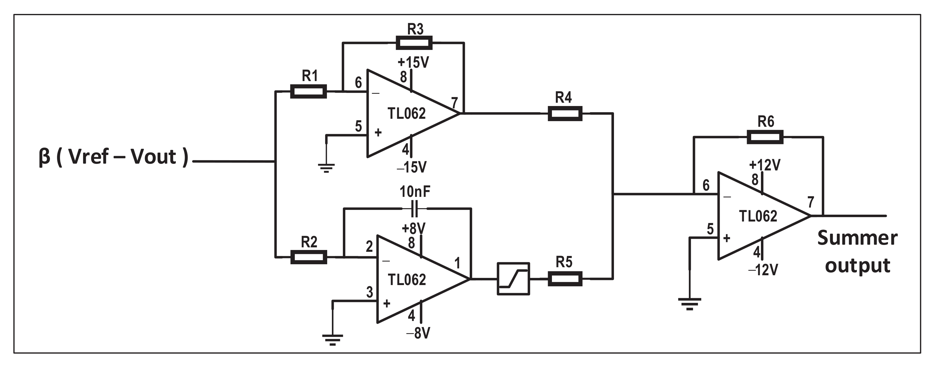
| Sr. | Resistances | Values |
|---|---|---|
| 1 | R1 | 1.2 K |
| 2 | R2 | 22 K |
| 3 | R3 | 8.2 K |
| 4 | R4 | 10 K |
| 5 | R5 | 10 K |
| 6 | R6 | 10 K |
| 7 | 0.103 |
Publisher’s Note: MDPI stays neutral with regard to jurisdictional claims in published maps and institutional affiliations. |
© 2021 by the authors. Licensee MDPI, Basel, Switzerland. This article is an open access article distributed under the terms and conditions of the Creative Commons Attribution (CC BY) license (https://creativecommons.org/licenses/by/4.0/).
Share and Cite
Yasin, A.R.; Yasin, A.; Riaz, M.; Ehab, M.; Raza, A. Filter Extracted Sliding Mode Approach for DC Microgrids. Electronics 2021, 10, 1882. https://doi.org/10.3390/electronics10161882
Yasin AR, Yasin A, Riaz M, Ehab M, Raza A. Filter Extracted Sliding Mode Approach for DC Microgrids. Electronics. 2021; 10(16):1882. https://doi.org/10.3390/electronics10161882
Chicago/Turabian StyleYasin, Abdul Rehman, Amina Yasin, Mudassar Riaz, Muhammad Ehab, and Ali Raza. 2021. "Filter Extracted Sliding Mode Approach for DC Microgrids" Electronics 10, no. 16: 1882. https://doi.org/10.3390/electronics10161882
APA StyleYasin, A. R., Yasin, A., Riaz, M., Ehab, M., & Raza, A. (2021). Filter Extracted Sliding Mode Approach for DC Microgrids. Electronics, 10(16), 1882. https://doi.org/10.3390/electronics10161882