Abstract
A terminal synergetic control (TSC) is designed in this work for a rotor side converter (RSC) of asynchronous generator (ASG)-based dual-rotor wind power (DRWP) systems. The design is based on a novel sliding manifold and aims at improving the ASG performance while minimizing active and reactive power undulations. The method performance and its effectiveness were studied under harmonic distortion (THD) of current, parameter variations and power undulations. Simulation results, carried out using Matlab software, confirmed the system’s robustness against parameter variations and its effectiveness in power undulations. The performance of the designed technique was further compared to that of integral-proportional (PI) controllers in terms of parameter variations, power undulations and THD value of current. While both controllers were able to reduce the effects of power undulations and protect the rotor circuit against over-currents, the proposed TSC was shown to be more effective than the classical PI controller in tracking power and minimizing the undulations effect.
1. Introduction
In the last two decades, the demand for electricity has increased significantly, which has led to the search for other alternative sources of electricity generation. Electricity significantly affects the local and global economy, while becoming one of the main reasons for the growth of the global economy. Among the different energy sources, thermal energy, water energy, photovoltaic systems and wind energy are the most popular [1]. Wind and photovoltaic energy are among the most popular and widely used sources of electricity production, due to the low cost of production and the simplicity of the generation system. For example, to generate electricity using wind energy, we only need a generator and a turbine. One of the most common causes of turbine generator damage is subsynchronous resonance (SSR) at subsynchronous frequencies [2]. In addition, SSR may damage other circuits such as transformers. Hurricanes and the migratory route of birds are among the obstacles not conducive to the deployment of wind power generators. The latter we find in the form of farms. These farms cannot be accomplished randomly, but there are several ways to achieve them. In [3], three different approaches are proposed to improve the wind farm layout problem. These ways are the Self-Informed Genetic Algorithm (SIGA), Conventional Genetic Algorithm (CGA) and Adaptive Genetic Algorithm (AGA). The results showed the effectiveness of the SIGA technique compared to the rest of the other methods. Among the disadvantages of wind farms, we find the wind currents generated by wind turbines, which drastically reduces the efficiency of the wind farm. In [4], a new algorithm is proposed in order to increase the efficiency of wind farms. This new algorithm is based on a support vector regression-guided genetic algorithm. This algorithm is robust and simple algorithms compared to other algorithms [5,6,7,8,9,10,11]. However, this algorithm provided better results compared to the classical method in improving wind farm efficiency [4].
During the last decade, many command strategies based on nonlinear command methods, super twisting algorithm, synergetic command (SC), neural networks (NN), sliding mode control (SMC), backstepping command (BC) and fuzzy logic have been proposed for the regulation of stator reactive and stator active powers of the asynchronous generators (ASG) [12,13,14,15]. The main objective of such robust command is to regulate and control the active power, and amelioration the effectiveness and controllability of the ASG-based wind power system.
Since direct active and reactive power command (DARPC) have been widely used for large-scale alternating current (AC) electric machines. The DARPC technique is similar to the direct torque control. The method is used because of its great simplicity and its very high performances, with a very fast response in active power and reactive power, for the control of ASG-based wind power. There are different scientific works on the DARPC technique and how to improve its performances. In [5], the DARPC technique was designed to control the ASG-based wind power. A novel DARPC switching table strategies for three-level AC/DC converter [6]. In [7], the DARPC technique was designed based on backstepping control to control the ASG-based wind turbines. In [8], the authors designed the use of a DARPC strategy with SMC theory applied to the ASG. A changed DARPC technique was designed based on the optimal transition route of ASG-based wind turbines [9]. In [10], a predictive DARPC strategy of wind power-driven ASGs connected to the grid was presented. In [11], stator active and reactive power proportional-integral (PI) regulators and traditional space vector modulation (SVM) were combined to replace the classical hysteresis controllers and lookup table. In [12], the DARPC technique based on a neural algorithm has been designed. In [13], an improved DARPC technique was designed based on fuzzy SMC methods. In [14], the DARPC technique based on natural switching surface has been designed. In [15], the authors designed the use of a DARPC strategy with two-stage Kalman filters applied to the ASG-based wind power. In [16], a multilevel DARPC technique of ASG has been proposed. A predictive DARPC technique is proposed to control the ASG-based wind power [17]. Experimental result is shown for the adaptive DARPC technique of ASG [18]. In [19], the authors designed the use of a DARPC strategy with STA method applied to the ASG. A variable STA method was proposed to improve the DARPC strategy of ASG-based wind power [20]. In [21] it is presented a decoupled DARPC technique of the ASG connected to an unbalanced power grid, executed in an orthogonal stationary reference frame related to the stator side. In [22], the voltage modulated DARPC method (VM-DARPC) was proposed to control the ASG-based wind turbines. To obtain better system performance, an integral SMC technique-based DARPC method is proposed for three-level neutral-point-clamped (3L-NPC) converters [23]. In [24], a modified DARPC method was proposed based on adaptive-gain second-order sliding mode to control and reduces the torque, active power and current ripples of the ASG-based wind power. In [25], the performance and effectiveness of the classic DARPC method are improved by using the SMC technique and the SVM strategy.
Recently, the SC method appears to be a new effective technique to deal with several robust strategy problems due to its optimality property and its inherent robustness to disturbances. The SC method was developed by Kolesnikov et al. [26] on the basis of the nonlinear control theory. The strategy was later applied to a many of energetic field, including problems in control power [27,28,29]. In [30], the authors presented the direct power control effectiveness of the ASG-based DRWP system using the SC method and showed that the power ripples reduced when using synergetic controllers.
The basic properties of SC technique are that it is well-suited for digital implementation; it gives constant switching frequency operation and gives better control of the off-manifold dynamics [31]. Direct active and reactive power have time-varying characteristics and, intrinsic nonlinear control which make the SC technique also be a well-suited method. In addition, among its characteristics of this method are order minimization, insensitivity to parameter variation and decoupling design procedure.
This work presents a new DARPC strategy to reduces harmonic distortion of current, active and reactive powers undulations, and improve the dynamic response of an ASG-based DRWP system using a modified space vector modulation (MSVM). This work represents a power study for ASG applications. The work objective is to improve the response time of torque and active power, and cycle life of the ASG-based DRWP system.
The originality of the designed strategy is the procedure to develop the terminal synergetic-based reactive and active power control strategy and to reduce the electromagnetic torque, stator current, reactive and active power undulations of ASG-based DRWP systems. Our work aims to analyze of the terminal synergetic-based power control strategy by providing proof of the regulator stability using Lyapunov theory.
A DARPC control ASG-DRWP system is developed to perform simulation analysis and validate the designed strategy. Numerical simulation results and a comparison with the classical strategy are given to validate the optimal transient performance of the proposed strategy.
The designed terminal SC technique based on active and reactive power control method is shown to acquire the following features:
- Terminal SC technique improves the dynamic response of the ASG-DRWP system.
- The proposed method offers very good transient performance compared to the classical method.
- Terminal synergetic control-based power control is more robust to parameters variation and external load disturbances.
- The proposed strategy is more simple algorithms.
This work addresses the following points: the modelling of the DRWP system is presented in Section 2. In Section 3 we present the mathematical form of an asynchronous generator. Section 4 gives an overview of the modified SVM technique for the traditional inverter. In Section 5 the new synergetic control theory based on the terminal sliding surface is presented. Section 6 provides the application of the terminal synergetic active and reactive power control scheme using neural modified SVM technique of the ASG-based DRWP system. The performances of the designed technique are discussed and demonstrated through numerical simulation in Section 7.
2. DRWP Model
In recent years, new technology has been invented to produce electrical energy from wind, even from a high-variable wind [32,33]. This technology is called dual-rotor wind turbines. This new wind turbine has two rotors. The first is the main rotor and the second is an auxiliary rotor. The number of mechanical components in a new wind turbine is higher than in the single rotor wind turbine system. This new wind turbine has been studied in several articles [34,35,36]. This new technology has an excellent performance in the regions of low and high wind speed, where different techniques to track the maximum power point (MPP) are proposed [37]. One of its advantages is that it collects much more energy from wind than traditional turbines. On the other hand, the dual-rotor wind turbines operate at lower tip speed ratios compared to the conventional wind turbine [38]. This new technology has several disadvantages, for example, difficulty to control, high financial cost, risk of subsynchronous resonance. It contains a large number of mechanical components compared to conventional wind turbines. Equation (1) represents the torque resulting from the dual-rotor wind turbine [39]:
where, the TAR and TMR the aerodynamic torque of the auxiliary and main rotors.
The torque of the auxiliary and main rotor is given by Equation (2):
where, ρ is the air density, λAR and λMR—the tip speed ration of the auxiliary and main rotors, wAR and wMR—the mechanical speed of the auxiliary and main rotors, and RMR and RAR—the blade radius of the auxiliary and main rotors.
The Cp is given by (3):
where, β is pitch angle.
In the DRWT system, the resulting power is the sum of the aerodynamic powers of the auxiliary and main rotor and is represented by the following equations:
where, PAR and PMR represent the mechanical power of the auxiliary and main rotors.
Equation (5) represents the tip speed ratios of the auxiliary and main rotors of DRWT system [40].
where, VMR is the speed of the unified wind on main rotor and Vw is the wind speed on an auxiliary rotor.
Equation (6) represents the wind speed in the main turbine:
where, CT is the trust coefficient (CT = 0.9), Vx is the velocity of the disturbed wind between rotors at point x, and x is the non-dimensional distance from the auxiliary rotor disk. The distance between the auxiliary and the main rotors is 15 m [41].
3. ASG Model
In the rotating field reference frame of Park, the mathematical model of the ASG is given by the following equations [42,43]. Equations (7) and (8) represents the rotor voltage and rotor flux of the ASG, respectively:
where, Lr is the inductance of the rotor, Ψdr and Ψqr are the rotor fluxes, M is the mutual inductance, Vdr and Vqr are the rotor voltages, Idr and Iqr are the rotor currents and Rr is the rotor resistance.
The voltage and the stator flux of the generator is shown in Equations (9) and (10), respectively:
where, Ls is the inductance of the stator, ωs is the electrical pulsation of the stator, Vds and Vqs are the stator voltages, Ψqs and Ψds are the stator fluxes and Rs is the stator resistance
Equation (11) represents the mechanical form of the ASG:
where, J is the inertia, Ω is the mechanical rotor speed, f is the viscous friction coefficient and Tr is the load torque.
The torque of the generator is given as follows:
where, p is the number of pole pairs and Te is the electromagnetic torque
The expression of both reactive and active powers is as follows:
4. Terminal Synergetic Control
In the mid-1990s, a new type of nonlinear method, named synergetic control (SC) was proposed by Kolesnikov. SC technique is a simple algorithm and robust nonlinear technique theory [30]. SC technique has also been widely used to control electrical machinery, for example, asynchronous motor and synchronous motor control.
The main advantages of the SC technique are that it is well-suited for digital implementation, it gives constant switching frequency operation and it gives better control of the off-manifold dynamics [44]. The design of the SC technique is similar to that of the SMC technique [45,46]. Equation (14) represent the principal of the classical SC method:
where, T presents convergence speed (T > 0) and S is the linear sliding surface.
The solution of Equation (15) is given by:
In classical SC method, we use the linear sliding surface, this makes the system state not converge to zero at the specified time. To overcome this problem, we proposed use the nonlinear sliding surface or terminal sliding surface. Thus, we have a new method of synergistic control called Terminal Synergetic Control (TSC). This proposed strategy is simple structure and similar to classical SC method. The difference between TSC and SC method lies in the type of sliding surface used. The TSC technique add nonlinear functions to manifold design and a TSC hyper plane is created and tracking errors on hyperplane will converge to zero in finite time [30].
The principle of the TSC technique it can be written as follows:
where, K is a positive gain and Ψ is the terminal sliding function.
Can be written the terminal sliding surface by the following equation:
where, β is the positive constant, S is the systems state or linear sliding surface and N is a positive number (1 < N < 2).
TSC technique can force system states to convergence to zero in finite time.
Lyapunov strategy function is considered as:
After differentiation one acquires:
So, considering (16):
Therefore, TSC stability is guaranteed due to the negative derivative of the Lyapunov function.
5. Modified SVM Technique
The use of digital technology allows the use of a specific three-phase modulation strategy, rather than deriving from the analogue technology that was originally designed as a single phase. Among these digital technologies, we have discovered vector modulation (SVM). It represents the modulation or control method most commonly used to control alternative current motors and induction machines. The vector modulation strategy is proposed by Der Broek [47]. It consists of generating a specified sequence of UPS states. Vector modulation is real-time modulation. It uses the fact that a vector can represent the three voltages of a three-phase zero-sum system.
Vector modulation is recognized as being the most efficient and the most widely used. the algorithm of this modulation becomes more complicated when it is applied to multilevel inverters. this technique has the following advantages over the rest of the modulation techniques [48].
- This modulation strategy is valid for all kinds of multilevel inverters.
- It directly controls the three phases of the inverter.
- The output current has a very low ripple
- The physical implementation is relatively simple.
This strategy is complicated and difficult to realize. To remedy this disadvantage, we propose here, another technique of modulation SVM, named modified SVM technique. The designed modified SVM strategy is very simple and easy to achieve in practice compared to classic SVM technique. The principle of the modified SVM consists in calculating the minimums value(Min) and maximums value (Max) of the rotor voltages [49]. Among the reasons for using modified SVM are the simplicity of the algorithm, it takes up less space, and the cost is lower compared to the classic SVM method.
The principle of the modified SVM (MSVM) technique is determined in four steps [42]:
- Step 1: calculate Min of three-phase voltages;
- Step 2: calculate Max of three-phase voltages;
- Step 3: calculate the sum of Min (V1, V2 and V3) and Max (V1, V2 and V3), where V1, V2 and V3 are the phase voltages;
- Step 4: generation of the Sa, Sb and Sc pulse series.
The principle diagram of this strategy is illustrated in the Figure 1 below.
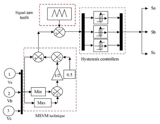
Figure 1.
Modified SVM technique.
6. Terminal Synergetic Active and Reactive Powers Control
In the 1990s, specifically in 1998, T. Noguchi [50] proposed a strategy for the DARPC method of asynchronous motors, which appeared in the literature under the name of DARPC (Direct Active and Reactive Power Control). The principle of DARPC technology is to directly adjust the active and reactive power of the ASG and determine its state by applying various voltage vectors to the inverter on the generator side. The two controlled variables are active power and reactive power, which are usually controlled by two hysteresis comparators [19]. The idea is to keep the amount of reactive power and active power within these hysteresis bands. The output of these regulators determines the best voltage vector applied at each switching moment. The general characteristics of a DPC command are simple algorithm, fast dynamic response, more harmonic distortion of current, indirect current control, high switching frequency and active power oscillations [20]. In order to improve the effectiveness of the traditional DARPC technique, the standard hysteresis comparators will be replaced by two terminal synergetic control techniques and the switching table by the neural modified SVM (NMSVM). The active and reactive power estimation block keeps the same shape as that established for classic DARPC, described in the papers [19,20]. The block diagram of the applied command structure is illustrated in Figure 2. The control of the voltage references of and in Figure 2 allows the control of the reactive and active power, as shown below. Thus, it is shown that the active and reactive power can be controlled by controlling the voltage components of the rotor part. In this terminal synergetic DARPC strategy (TSC-DARPC), the stator reactive and active power are controlled by two terminal synergetic controllers, while the NMSVM technique replaces the classical switching table.
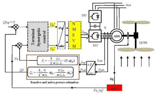
Figure 2.
DARPC system of ASG with the applications of proposed terminal synergetic control.
This control by TSC-DARPC with NMSVM technique has the advantages of vector control and classical DARPC to overcome the problem of undulations in power and generated by the ASG. TSC regulators and the NMSVM technique are used to obtain a fixed switching frequency and less pulsation of the powers.
The estimated reactive and active powers are given as:
where:
6.1. Design Terminal Synergetic Active and Reactive Powers
In terminal synergetic DARPC strategy, two TSC regulators are used to regulate the stator reactive and active powers of ASG-based DRWP systems. The stator active and reactive power controllers generate the reference voltages Vdr* and Vqr*, respectively, by using (27)–(30) as follows. The terminal sliding surface for active and reactive power controllers is defined by:
with:
Then the derivative of it is given by:
To acquire Vdr* and Vqr*, we use Equations (16) and (27)–(29). This is carried out by substituting Equation (28) into Equation (27). Then we derive Equation (27) to acquire Equation (29). Finally, to obtain Equation (30), Equations (16) and (29) are used.
Equation (30) represents the two components of the rotary voltage of the machine.
with the terms and are shown in Equations (27) and (29), respectively.
The block diagram of the designed TSC controllers for active and reactive power references is given in Figure 3. The direct and quadrature rotor voltage reference values are calculated using Figure 3a,b, respectively. Since the mathematical model of the system is not necessary, it turns out that the designed technique is less complicated compared to other methods, such as the high-order SMC strategy. Furthermore, the Sign function is not required.
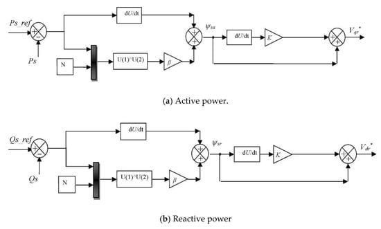
Figure 3.
The TSC controllers designed for active and reactive power references.
This method is proposed in order to improve the performance and effectiveness of direct power control. In addition to reducing active power fluctuations, as well as the harmonic value of the network current.
6.2. Design of Neural MSVM Technique
The designed technique (neural MSVM) is a new modulation strategy which consists of using the neural controllers to learn the principle of the classical hysteresis comparators of MSVM method. This designed strategy is simple modulation structure and robust. In [51], experimental results have indicated that the neural SVM strategy has had satisfying inverter effectiveness compared to traditional PWM and traditional SVM techniques. One of the benefits of using the proposed new method is to obtain a more robust technology, which has the following advantages: reduction of current ripples, obtaining a fast response and improved accuracy compared to traditional modified SVM strategy. On the other hand, the neural MSVM technique reduces the THD value of voltage/current of the output inverter. Moreover, this method provides a constant switching frequency due to the use of neural networks instead of classical hysteresis comparators. The neural MSVM method is a modification of the classical MSVM method based on the use of neural networks in place of conventional hysteresis comparators. The structure of the modified SVM technique based on the ANN algorithm is shown in Figure 4. From the analysis of Figure 4, it is observed that this method is simpler than the classic method, easy to implement, uncomplicated and does not require a specialist for adjusting the control loops. It is known that neural networks are characterized by accuracy, high response speed and are not affected by noise. These advantages are combined in the modified SVM method in order to obtain a new SVM method, more robust and with a higher response speed, and therefore having the possibility to reduce more current ripples at the level of the machine. These results are confirmed by the experimental results presented in [51], which showed the effectiveness of the use of neural networks in the traditional SVM strategy. By studying paper [51], we found that the neural SVM method can reduce the current ripples and THD value compared to the PWM and classical SVM methods. Moreover, this intelligent SVM method can be applied to the multi-level inverter easily in contrast with the classical SVM method. The parameters of the ANN algorithm for the MSVM strategy are shown in Table 1. On the other hand, the ANN algorithm is the most used in control techniques because the ANN algorithm is simple, robust and offers high accuracy in defining control references.
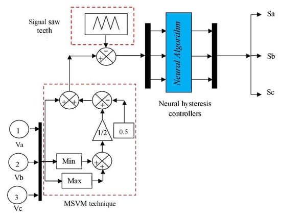
Figure 4.
Neural modified SVM (NMSVM) technique.

Table 1.
Parameters of the neural algorithm.
The structure of the neural algorithm of the classic hysteresis comparator that implements the MSVM strategy is a neural controller, with 12 neurons in the hidden layer, one linear input node and one neuron in the output layer. As shown in Figure 5. The neural algorithm consists of two layers. The first layer and the second layer are presented in Figure 6 and Figure 7, respectively.
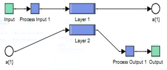
Figure 5.
Structure of ANN hysteresis comparators.
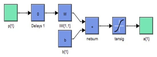
Figure 6.
Layer 1.
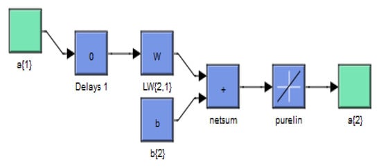
Figure 7.
Layer 2.
7. Numerical Simulation Results
The control techniques by conventional DPC and TSC-DARPC with NMSVM technique, applied to the ASG (1.5 MW) were validated by numerical simulation using the Matlab/Simulink environment. The parameters of the ASG used for the simulation are given in the Appendix A.
The simulation results obtained are shown in Figure 8, Figure 9, Figure 10, Figure 11, Figure 12, Figure 13, Figure 14, Figure 15 and Figure 16. Note that the reactive and active powers that are measured for stator will accurately follow their references, with high dynamics for both control loops (Figure 8 and Figure 9). On the other hand, we notice from Figure 10, which illustrates the electromagnetic torque of the two control techniques (classic DARPC and TSC-DARPC with NMSVM technique) of the ASG, that the electromagnetic torque depends directly on the stator active power. This is reflected by its shape identical to the latter. Figure 11 represents the stator current signal of the machine. From this Figure, the shape of the stator current is sinusoidal, and on the other hand, its value is related to the reference value of the active power and the system itself. Figure 12, Figure 13, Figure 14, illustrate zooms on the curves of the active power, stator current and the torque of the ASG.
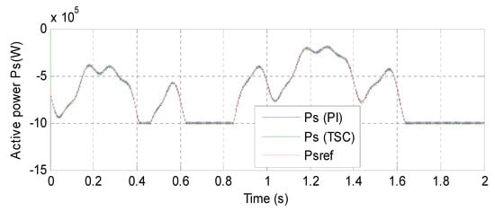
Figure 8.
Active power.
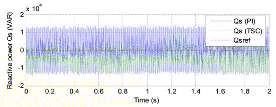
Figure 9.
Reactive power.
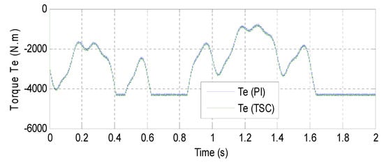
Figure 10.
Torque.
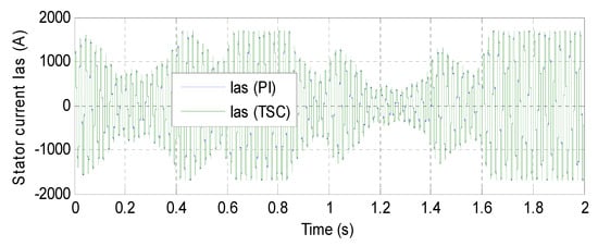
Figure 11.
Current.
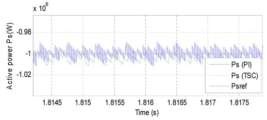
Figure 12.
Zoom (Active power).
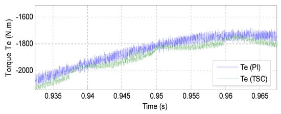
Figure 13.
Zoom (Torque).
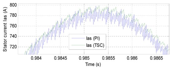
Figure 14.
Zoom (Current).
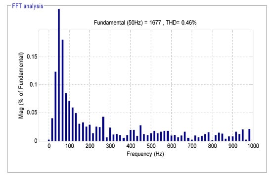
Figure 15.
THD of current (DARPC-PI).
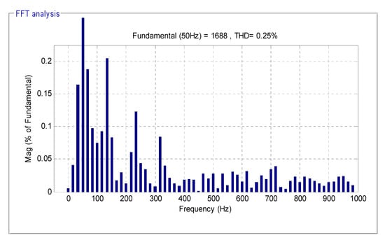
Figure 16.
THD of current (TSC-DARPC with NMSVM).
By looking at Figure 9 and Figure 12, we notice that the TSC-DARPC with NMSVM technique reduces much more the ripples of the active and reactive powers compared with the DARPC-PI method. Figure 15 and Figure 16 show the harmonic spectra of a phase of the stator current for the two DARPC controls analysed in this paper. Note that the value of the THD is reduced for the control by TSC-DARPC with NMSVM technique (THD = 0.25%) compared to the control by conventional DARPC-PI (THD = 0.46%) and even for the DARPC with 12 sectors (THD = 0.40%) proposed in [52]. These results allow us to conclude that the two-level TSC-DARPC with NMSVM technique is effective in reducing the ripple of the stator currents.
Looking to Figure 12, Figure 13 and Figure 14 that illustrate zooms on the curves of the active power, stator current and the torque of the ASG, it is worth mentioning that the control by TSC-DARPC with NMSVM technique presents less undulations at the level of these curves compared to DARPC with PI controllers.
B. Robustness Test
To test the robustness of the two designed DARPC methods of ASG-based DRWP systems, the influence of parametric variations on the performance of these methods is estimated by the sensitivity analysis method. The robustness of the three commands resulting from the modification of the ASG parameters is tested following the specifications below:
- Resistances Rs and Rr are multiplied by 2;
- Inductances Ls, Lr and M are divided by 2;
- The mechanical speed is assumed to be fixed and equal to its nominal value.
The simulation results obtained are illustrated in Figure 17, Figure 18, Figure 19, Figure 20, Figure 21, Figure 22, Figure 23, Figure 24 and Figure 25. From the analysis of these results, it can be seen that the excessive parametric variations performed on the ASG model generated clear effects on the curves of the electromagnetic torque, stator reactive and active power of the two proposed commands (Figure 17 and Figure 18). These effects appeared on the two operating regimes of the ASG: transient and permanent regime. Figure 24 and Figure 25 represent the harmonic spectra of a phase of the stator current for the three proposed commands, relating to this test. Note that, the value of the THD is always reduced for the TSC-DARPC with NMSVM technique (THD = 0.70%) compared to that of the DARPC with PI regulators (THD = 0.94%) and the classic DARPC (THD = 2.39%) [53].
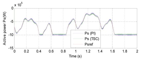
Figure 17.
Active power.
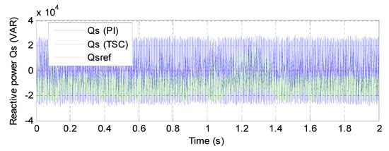
Figure 18.
Reactive power.
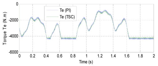
Figure 19.
Torque.
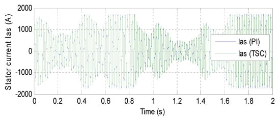
Figure 20.
Current.
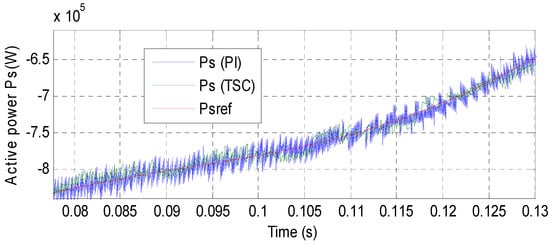
Figure 21.
Zoom (Active power).
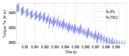
Figure 22.
Zoom (Torque).
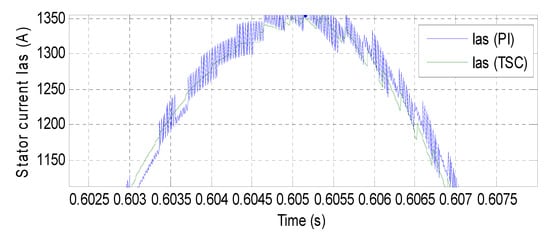
Figure 23.
Zoom (Current).
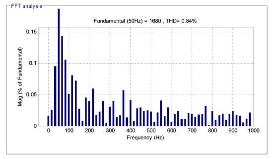
Figure 24.
THD of current (PI-DARPC).
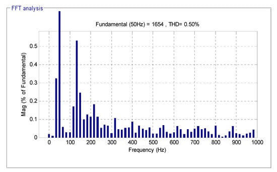
Figure 25.
THD of current (TSC-DARPC with NMSVM).
Figure 21, Figure 22 and Figure 23, illustrate the zooms on the stator active power, electromagnetic torque and current of the GADA. From these figures, it can be seen that the undulations at these curves are always minimized for the TSC-DARPC with NMSVM technique compared to DARPC with PI controllers.
In Table 2, we present a comparative summary of the two types of DARPC techniques used in this work.
Table 2.
Comparative study between DARPC-PI and TSC-DARPC.
According to the results presented in Table 2, it is undoubtedly observed that the TSC-DARPC with NMSVM technique is the most efficient in terms of minimizing ripples of different curves (powers, electromagnetic torque and stator currents) compared to the classical DARPC method. Therefore, the TSC-DARPC-ASG system ensures a good quality of power supplied to the network.
8. Conclusions
In this work, we have presented two DARPC control methods applied to the ASG. We started our study by modelling the dual-rotor wind turbine which uses a two-rotor used for the generation of electrical power.
As it has been seen in the previous sessions and even in the literature, classical DARPC is known for its major drawback presented by ripples appearing in the regulated variables. One solution has been applied in this work to remedy this problem, namely the TSC-DARPC technique with neural modified SVM strategy. A comparison of the two types of DARPC control used in this work was carried out by numerical simulations. It was noticed that the TSC-DARPC control with neural modified SVM presents better performances compared to the traditional DARPC method, appeared especially in the attenuation of the ripples at the level of the regulated variables.
The TSC-DARPC control with neural modified SVM technique that we have developed presents a satisfactory tracking of the reference and considerably reduces the ripples of powers, torque and stator currents. It should be noted that the TSC regulator does not in all cases make it possible to reduce the stator reactive and active power ripples of the ASG. However, there are modern techniques that cope better with these requirements and which are robust and less sensitive.
Our next work is devoted to the application of this proposed method in order to confirm the results obtained.
Author Contributions
Conceptualization, H.B.; methodology, H.B.; software, H.B.; validation, N.B.; investigation, H.B.; resources, H.B. and N.B.; data curation, N.B.; writing—original draft preparation, H.B.; supervision, N.B.; project administration, N.B.; Formal analysis: N.B.; Funding acquisition: N.B.; Visualization: N.B.; writing—review and editing: N.B. and H.B. All authors have read and agreed to the published version of the manuscript.
Funding
There is no funding available for this.
Conflicts of Interest
The authors declare no conflict of interest.
Appendix A
Table A1.
ASG-DRWP parameters.
Table A1.
ASG-DRWP parameters.
| Pn | 1.5 MW |
| Ω | 150 rad/s |
| P | 2 |
| Vn | 380 V |
| Rr | 0.021 Ω |
| Lr | 0.0136 H |
| Lm | 0.0135 H |
| Rs | 0.012 Ω |
| Ls | 0.0137 H |
| Fr | 0.0024 Nm.s/rad |
| PDRWT | 1.5 MW |
| dM | 51 m |
| dA | 26.4 m |
References
- Liaquat, S.; Zia, M.F.; Benbouzid, M. Modeling and Formulation of Optimization Problems for Optimal Scheduling of Multi-Generation and Hybrid Energy Systems: Review and Recommendations. Electronics 2021, 10, 1688. [Google Scholar] [CrossRef]
- Peng, X.; Chen, R.; Zhou, J.; Qin, S.; Bi, R.; Sun, H. Research on Mechanism and Damping Control Strategy of DFIG-Based Wind Farm Grid-Connected System SSR Based on the Complex Torque Method. Electronics 2021, 10, 1640. [Google Scholar] [CrossRef]
- Xing, L.J.; Feng, L. Wind farm layout optimization using self-informed genetic algorithm with information guided exploitation. Appl. Energy 2019, 248, 429–445. [Google Scholar] [CrossRef]
- Xing, L.J.; Feng, L.; Li, W.; Wei-Jen, L. Wind farm layout optimization based on support vector regression guided genetic algorithm with consideration of participation among landowners. Energy Convers. Manag. 2019, 196, 1267–1281. [Google Scholar] [CrossRef]
- Hu, B.; Nian, H.; Yang, J.; Li, M.; Xu, Y. High-frequency resonance analysis and reshaping control strategy of DFIG system based on DPC. IEEE Trans. Power Electron. 2021, 36, 7810–7819. [Google Scholar] [CrossRef]
- Kulikowski, K.; Sikorski, A. New DPC look-up table methods for three-level AC/DC converter. IEEE Trans. Ind. Electron. 2016, 63, 7930–7938. [Google Scholar] [CrossRef]
- Xiong, P.; Sun, D. Backstepping-based DPC strategy of a wind turbine-driven DFIG under normal and harmonic grid voltage. IEEE Trans. Power Electron. 2016, 31, 4216–4225. [Google Scholar] [CrossRef]
- Gui, Y.; Xu, Q.; Blaabjerg, F.; Gong, H. Sliding mode control with grid voltage modulated DPC for voltage source inverters under distorted grid voltage. CPSS Trans. Power Electron. Appl. 2019, 4, 244–254. [Google Scholar] [CrossRef]
- Hamed, H.A.; Abdou, A.F.; Moursi, M.S.E.; EL-Kholy, E.E. A modified DPC switching technique based on optimal transition route for of 3L-NPC converters. IEEE Trans. Power Electron. 2018, 33, 1902–1906. [Google Scholar] [CrossRef]
- Hu, J. Improved dead-beat predictive DPC strategy of grid-connected DC–AC converters with switching loss minimization and delay compensations. IEEE Trans. Ind. Inform. 2013, 9, 728–738. [Google Scholar] [CrossRef]
- Malinowski, M.; Jasinski, M.; Kazmierkowski, M.P. Simple direct power control of three-phase PWM rectifier using space-vector modulation (DPC-SVM). IEEE Trans. Ind. Electron. 2004, 51, 447–454. [Google Scholar] [CrossRef]
- Benbouhenni, H.; Boudjema, Z.; Belaidi, A. Power control of DFIG in WECS using DPC and NDPC-NPWM methods. Math. Model. Eng. Probl. 2020, 7, 223–236. [Google Scholar] [CrossRef]
- Huang, J.; Zhang, A.; Zhang, H.; Ren, Z.; Wang, J.; Zhang, L.; Zhang, C. Improved direct power control for rectifier based on fuzzy sliding mode. IEEE Trans. Control. Syst. Technol. 2014, 22, 1174–1180. [Google Scholar] [CrossRef]
- Ge, J.; Zhao, Z.; Yuan, L.; Lu, T.; He, F. Direct power control based on natural switching surface for three-phase PWM rectifiers. IEEE Trans. Power Electron. 2015, 30, 2918–2922. [Google Scholar] [CrossRef]
- Xiahou, K.; Li, M.S.; Liu, Y.; Wu, Q.H. Sensor fault tolerance enhancement of DFIG-WTs via perturbation observer-based DPC and two-stage kalman filters. IEEE Trans. Energy Convers. 2018, 33, 483–495. [Google Scholar] [CrossRef]
- Rivera, S.; Kouro, S.; Wu, B.; Alepuz, S.; Malinowski, M.; Cortes, P.; Rodriguez, J. Multilevel direct power control-A generalized approach for grid-tied multilevel converter applications. IEEE Trans. Power Electron. 2014, 29, 5592–5604. [Google Scholar] [CrossRef]
- Abad, G.; RodrÍguez, M.Á.; Poza, J. Two-level VSC-based predictive direct power control of the doubly fed induction machine with reduced power ripple at low constant switching frequency. IEEE Trans. Energy Convers. 2008, 23, 570–580. [Google Scholar] [CrossRef]
- Djoudi, A.; Bacha, S.; Chekireb, H.; Iman-Eini, H.; Boudinet, C. Adaptive sensorless SM-DPC of DFIG-based WECS under disturbed grid: Study and experimental results. IEEE Trans. Sustain. Energy 2018, 9, 570–581. [Google Scholar] [CrossRef]
- Shah, P.; Mehta, A.J. Direct Power Control of DFIG using Super-Twisting Algorithm based on Second-Order Sliding Mode Control. In Proceedings of the 14th International Workshop on Variable Structure Systems (VSS), Nanjing, China, 1–4 June 2016; pp. 136–141. [Google Scholar] [CrossRef]
- Shah, P.; Mehta, A.J. Direct Power Control of Grid-Connected DFIG using Variable Gain Super-Twisting Sliding Mode Controller for Wind Energy Optimization. In Proceedings of the IECON 2017—43rd Annual Conference of the IEEE Industrial Electronics Society, Beijing, China, 29 October–1 November 2017; pp. 2448–2454. [Google Scholar] [CrossRef]
- Pura, P.; Iwański, G. Rotor Current Feedback Based Direct Power Control of a Doubly Fed Induction Generator Operating with Unbalanced Grid. Energies 2021, 14, 3289. [Google Scholar] [CrossRef]
- Cheng, P.; Wu, C.; Ning, F.; He, J. Voltage Modulated DPC Strategy of DFIG Using Extended Power Theory under Unbalanced Grid Voltage Conditions. Energies 2020, 13, 6077. [Google Scholar] [CrossRef]
- Lin, H.; Leon, J.I.; Luo, W.; Marquez, A.; Liu, J.; Vazquez, S.; Franquelo, L.G. Integral Sliding-Mode Control-Based Direct Power Control for Three-Level NPC Converters. Energies 2020, 13, 227. [Google Scholar] [CrossRef] [Green Version]
- Han, Y.; Ma, R. Adaptive-Gain Second-Order Sliding Mode Direct Power Control for Wind-Turbine-Driven DFIG under Balanced and Unbalanced Grid Voltage. Energies 2019, 12, 3886. [Google Scholar] [CrossRef] [Green Version]
- Zoghlami, M.; Kadri, A.; Bacha, F. Analysis and Application of the Sliding Mode Control Approach in the Variable-Wind Speed Conversion System for the Utility of Grid Connection. Energies 2018, 11, 720. [Google Scholar] [CrossRef] [Green Version]
- Kolesnikov, A.A. Synergetic Control Theory. Energoatomizdat, Moscow Taganrog, Russia. 1994. Available online: https://citeseerx.ist.psu.edu/viewdoc/download?doi=10.1.1.13.7213&rep=rep1&type=pdf (accessed on 9 July 2021).
- Medjbeur, L.; Harmas, M.N.; Benaggoune, S. Robust induction motor control using adaptive fuzzy synergetic control. J. Electr. Eng. 2012, 12, 37–42. [Google Scholar]
- Chi-Hua, L.; Ming-Ying, H. A finite time synergetic control scheme for robot manipulators. Comput. Math. Appl. 2012, 64, 1163–1169. [Google Scholar] [CrossRef] [Green Version]
- Nicola, M.; Nicola, C.I. Sensorless Control of PMSM based on Fractional Order Synergetic Control. In Proceedings of the 2020 International Conference and Exposition on Electrical and Power Engineering (EPE), Iasi, Romania, 22–23 October 2020; pp. 308–313. [Google Scholar] [CrossRef]
- Benbouhenni, H. Synergetic control theory scheme for asynchronous generator based dual-rotor wind power. J. Electr. Eng. Electron. Control. Comput. Sci. 2021, 7, 19–28. [Google Scholar]
- Santi, E.; Monti, A.; Li, D.; Proddutur, K.; Dougal, R.A. Synergetic control for power electronics applications: A comparison with the sliding mode approach. J. Circuits Syst. Comput. 2004, 13, 737–760. [Google Scholar] [CrossRef] [Green Version]
- Bizon, N. Optimal operation of fuel cell/wind turbine hybrid power system under turbulent wind and variable load. Appl. Energy 2018, 212, 196–209. [Google Scholar] [CrossRef]
- Benbouhenni, H. Application of STA methods and modified SVM strategy in direct vector control system of ASG integrated to dual-rotor wind power: Simulation studies. Int. J. Smart Grid 2021, 5, 62–72. [Google Scholar]
- Yahdou, A.; Djilali, A.B.; Boudjema, Z.; Mehedi, F. Improved vector control of a counter-rotating wind turbine system using adaptive backstepping sliding mode. J. Eur. Syst. Autom. 2020, 53, 645–651. [Google Scholar] [CrossRef]
- Habib, B.; Lemdani, S. Combining synergetic control and super twisting algorithm to reduce the active power undulations of doubly fed induction generator for dual-rotor wind turbine system. Electr. Eng. Electromechanics 2021, 3, 8–17. [Google Scholar] [CrossRef]
- Beik, O.; Al-Adsani, A.S. Active and passive control of a dual rotor wind turbine generator for DC Grids. IEEE Access 2021, 9, 1987–1995. [Google Scholar] [CrossRef]
- Bizon, N. Optimization of the Fuel Cell Renewable Hybrid Power Systems, 1st ed.; Springer: Berlin/Heidelberg, Germany, 2020. [Google Scholar] [CrossRef]
- Irawan, Y.H.; Bramantya, M.A. Numerical Simulation of the Effect of Axial Distance between Two Rotors in Counter-Rotating Wind Turbines. In Proceedings of the 2nd International Conference on Science and Technology-Computer (ICST), Yogyakarta, Indonesia, 27–28 October 2016; pp. 1–5. [Google Scholar] [CrossRef]
- Kale, S.A.; Sapali, S.N. Power Output Prediction and Primary Evaluation of a Unidirectional Co-Axial Series Rotors Wind Turbine. In Proceedings of the 2013 Annual International Conference on Emerging Research Areas and 2013 International Conference on Microelectronics, Communications and Renewable Energy, Kanjirapally, India, 4–6 June 2013; pp. 1–3. [Google Scholar] [CrossRef]
- Mohamed, A.; El-Baz, A.; Abd-ELaziz, N.; Mostafa, A. Computational Investigation of Ducted Dual Rotor Wind Turbine. In Proceedings of the 2019 Novel Intelligent and Leading Emerging Sciences Conference (NILES), Giza, Egypt, 28 October–4 November 2019; pp. 29–33. [Google Scholar] [CrossRef]
- Yahdou, A.; Hemici, B.; Boudjema, Z. Sliding mode control of dual rotor wind turbine system. Mediterr. J. Meas. Control. 2015, 11, 412–419. [Google Scholar]
- Benbouhenni, H.; Boudjema, Z.; Belaidi, A. Indirect vector control of a DFIG supplied by a two-level FSVM inverter for wind turbine system. Majlesi J. Electr. Eng. 2019, 13, 45–54. [Google Scholar]
- Boudjema, Z.; Taleb, R.; Djerriri, Y.; Yahdou, A. A novel direct torque control using second order continuous sliding mode of a doubly fed induction generator for a wind energy conversion system. Turk. J. Electr. Eng. Comput. Sci. 2017, 25, 965–975. [Google Scholar] [CrossRef] [Green Version]
- Kolesnikov, A.A. Introduction of Synergetic Control. In Proceedings of the 2014 American Control Conference, Portland, OR, USA, 4–6 June 2014; pp. 3013–3016. [Google Scholar] [CrossRef]
- Sriprang, S.; Nahid-Mobarakeh, B.; Takorabet, N.; Pierfederici, S.; Kumam, P.; Bizon, N.; Taghavi, N.; Vahedi, A.; Mungporn, P.; Thounthong, P. Design and control of permanent-magnet assisted synchronous reluctance motor with copper loss minimization sing MTPA. J. Electr. Eng. 2020, 71, 11–19. [Google Scholar] [CrossRef]
- Thounthong, P.; Sikkabut, S.; Poonnoy, N.; Mungporn, P.; Yodwong, B.; Kumam, P.; Bizon, N.; Nahid-Mobarakeh, B.; Pierfederici, S. Nonlinear differential flatness-based speed/torque control with state-observers of permanent magnet synchronous motor drives. IEEE T Ind. Appl. 2018, 54, 2874–2884. [Google Scholar] [CrossRef]
- Van der Broeck, H.W.; Skudelny, H.; Stanke, G.V. Analysis and realization of a pulse width modulator based on voltage space vectors. IEEE Trans. Ind. Appl. 1988, 24, 142–150. [Google Scholar] [CrossRef]
- Mehedi, F.; Yahdou, A.; Djilali, A.B.; Benbouhenni, H. Direct torque fuzzy controlled drive for multi-phase IPMSM based on SVM technique. J. Eur. Syst. Autom. 2020, 53, 259–266. [Google Scholar] [CrossRef]
- Mehedi, F.; Benbouhenni, B.; Nezli, L.; Boudana, D. Feedforward neural network-DTC of multi-phase permanent magnet synchronous motor using five-phase neural space vector pulse width modulation strategy. J. Eur. Syst. Autom. 2021, 54, 345–354. [Google Scholar] [CrossRef]
- Noguchi, T.; Tomiki, H.; Kondo, S.; Takahashi, I. Direct power control of PWM converter without power-source voltage sensors. IEEE Trans. Ind. Appl. 1998, 34, 473–479. [Google Scholar] [CrossRef]
- Boudjema, Z.; Benbouhenni, H.; Bouhani, A.; Chabni, F. DSPACE implementation of a neural SVPWM technique for a two level voltage source inverter. Iran. J. Electr. Electron. Eng. 2021, 17, 1–9. [Google Scholar]
- Yusoff, N.A.; Razali, A.M.; Karim, K.A.; Sutikno, T.; Jidin, A. A concept of virtual-flux direct power control of three-phase AC-DC converter. Int. J. Power Electron. Drive Syst. 2017, 8, 1776–1784. [Google Scholar] [CrossRef]
- Amrane, F.; Chaiba, A.; Badr Eddine, B.; Saad, M. Design and implementation of high performance field oriented control for grid-connected doubly fed induction generator via hysteresis rotor current controller. Rev. Roum. Sci. Tech. Electrotechn. Energ. 2016, 61, 319–324. [Google Scholar]
Publisher’s Note: MDPI stays neutral with regard to jurisdictional claims in published maps and institutional affiliations. |
© 2021 by the authors. Licensee MDPI, Basel, Switzerland. This article is an open access article distributed under the terms and conditions of the Creative Commons Attribution (CC BY) license (https://creativecommons.org/licenses/by/4.0/).