Article

Study on the Wear Resistance of Laser Cladding h-BN Reinforced by TiCN/Ni-Based Coating on TC4 Alloy Surface


1
International Shipping Research Institute, Jiujiang Polytechnic University of Science and Technology, Gongqing City 332020, China
2
Daqing Oilfield Perforating Equipment Co., Ltd., Chuangyezhuang, Honggang District, Daqing 163000, China
3
Daqing Oilfield Powerlift Industry Co., Ltd., High-Tech District, Daqing 163000, China
4
School of Intelligent Vehicle, Guangzhou Polytechnic University, No. 1342 Shiliang Road, Panyu District, Guangzhou 511483, China
*
Author to whom correspondence should be addressed.
Coatings 2026, 16(4), 490; https://doi.org/10.3390/coatings16040490
Submission received: 1 March 2026 / Revised: 2 April 2026 / Accepted: 15 April 2026 / Published: 18 April 2026

Abstract

Three Ni-based composite coatings with varying TiCN/h-BN contents were fabricated on the surface of Ti-6Al-4V (TC4) alloy by laser cladding. The coatings were formulated with a fixed 15% TiCN and 0%, 2% and 5% h-BN, corresponding to L1–L3 coatings. The microstructure and phase composition were fully characterized and investigated. In addition, the microhardness and wear resistance of the coating were evaluated too. The analysis revealed that the L1–L3 coatings primarily consisted of Ti, TiNi, Ti(C, N) and TiAl3 phases. Microstructural analysis indicated that the top region of the coating was predominantly composed of granular crystals, while the middle and bonding regions featured a combination of dendrites and white granular crystals. The average microhardness values for the L1–L3 coatings were measured at 1203.8, 1216.8 and 1235.5 HV0.2, respectively, while the corresponding wear volumes were 0.098, 0.094 and 0.086 mm3. As the h-BN content increased, the microstructure of the Ni-based composite coating became finer and finer. Some TiB particles were also generated in the coating, which made the average microhardness and wear resistance increase gradually. Notably, the coating with 5% h-BN demonstrated the highest average microhardness and optimal wear resistance. Compared with the substrate, 5% h-BN increased the wear resistance of the substrate by 47.6%. The primary wear mechanism observed was abrasive wear.

1. Introduction

Ti-6Al-4V (TC4) alloy is renowned for its high specific strength, low density, corrosion resistance, and excellent high-temperature performance. Thus, it is used in some critical fields, such as aerospace, biomedical devices, and the automotive industry [1,2,3]. However, as the application scope of TC4 alloy continues to expand, the operational environments it encounters have become increasingly complex. Despite its many advantages, TC4 alloy is prone to wear-induced failure due to its relatively poor wear resistance, limiting its performance in demanding conditions. To solve wear and friction issue, many avenues have been studied [4]. Laser cladding technology to deposit wear-resistant coatings on TC4 alloy surfaces has emerged as a highly effective solution. Currently, the most commonly used materials for laser cladding are self-fluxing alloy powders, such as Co-based, Ni-based, and Fe-based powders [5,6,7]. Among these, Ni-based self-fluxing alloy powders are the most popular due to their balanced cost-effectiveness, superior wear resistance, excellent wettability, and abundant raw material availability. These advantages have led to their widespread adoption in various industrial applications [8,9].
In recent years, researchers have conducted extensive studies on laser cladding for the surface modification of titanium alloys [10,11,12], contributing significantly to the surface strengthening of TC4 alloy. For instance, Cai et al. [13] fabricated a TiC-reinforced Ni60 composite coating on TC4 alloy by laser cladding. The results demonstrated that the coating with 50% TiC exhibited the highest microhardness, reaching 1000 HV. Compared to the substrate, the wear resistance of the coating was markedly improved, with a weight loss of only 5 mg. h-BN is a white crystal with a graphite-like layered structure, so it is often called ‘white graphite’. It has excellent chemical stability and good lubrication performance, so it is usually used in laser cladding, nano-electronic devices, and other fields [14]. h-BN has also been successfully used in aerospace applications [15], for example, in the application of h-BN-based composite ceramic materials in the antenna window cover plate. Ren et al. [16] developed h-BN-reinforced Ni-based composite coatings on TC4 by laser and investigated their wear properties under varying loads. The coatings consisted of a Ni-based solid solution as the toughening phase, CrB, TiC, and TiB2 as reinforcing phases, and h-BN as a lubricating phase. The findings revealed that the average microhardness of the coating with 5% h-BN was approximately three times that of the TC4 substrate. Additionally, under loads from 2 to 8 N, the wear rate was reduced by more than 50% compared to the substrate. Basanti et al. [17] successfully synthesized a composite coating containing h-BN and B4C hard phases on TC4 alloy by laser. The study identified the formation of nanocrystalline phases such as C3N4, B13C2, and TiCN within the coating, resulting in a significant enhancement in microhardness, with a maximum value of 2814 HV. Further, the friction coefficient was as low as 0.109. Similarly, Liu et al. [18] prepared TiN and h-BN-reinforced Ni-based composite coatings on TC4 by laser. The results indicated that the coating with 30% TiN and 15% h-BN had a higher microhardness, which was approximately 2.7 times higher than that of the substrate (870 HV0.2). The wear rate of the coating was 0.018 lower than that of the coating without h-BN. In summary, Ni-based coatings reinforced with TiC, TiN, or h-BN have been successfully fabricated on TC4 substrates. The TiCN, a non-oxide ceramic material, combines the advantageous properties of both TiC and TiN [19,20,21,22]. However, before this study, no research had explored the incorporation of TiCN and h-BN together in coatings on TC4 substrates. So it is a meaningful study to develop the mechanism of TiCN and h-BN in Ni-based coatings.
In this study, Ni-based composite coatings with varying TiCN/h-BN contents were fabricated on a TC4 substrate by laser cladding. The influence of different h-BN contents in Ni-based coatings was systematically investigated on the microstructure, microhardness, and wear resistance. The findings serve as a theoretical foundation for designing and optimizing laser cladding processes, which aim at enhancing the surface properties of TC4 alloy.

2. Experimental

2.1. Experimental Materials

The Ti-6Al-4V (TC4) alloy served as the substrate (Dongguan Yi Titanium Metal Material Co., Ltd., Dongguan, China). The chemical composition of TC4 alloy (mass fraction, wt.%) is as follows: 6.01% Al, 3.84% V, 0.30% Fe, 0.15% Si, 0.10% C, 0.15% N, 0.15% O, and balanced Ti (89.3%). The dimension of the substrate was 50 × 30 × 10 mm. Prior to further processing, the substrates were polished to eliminate the surface oxide layer and were subsequently cleaned with anhydrous ethanol.
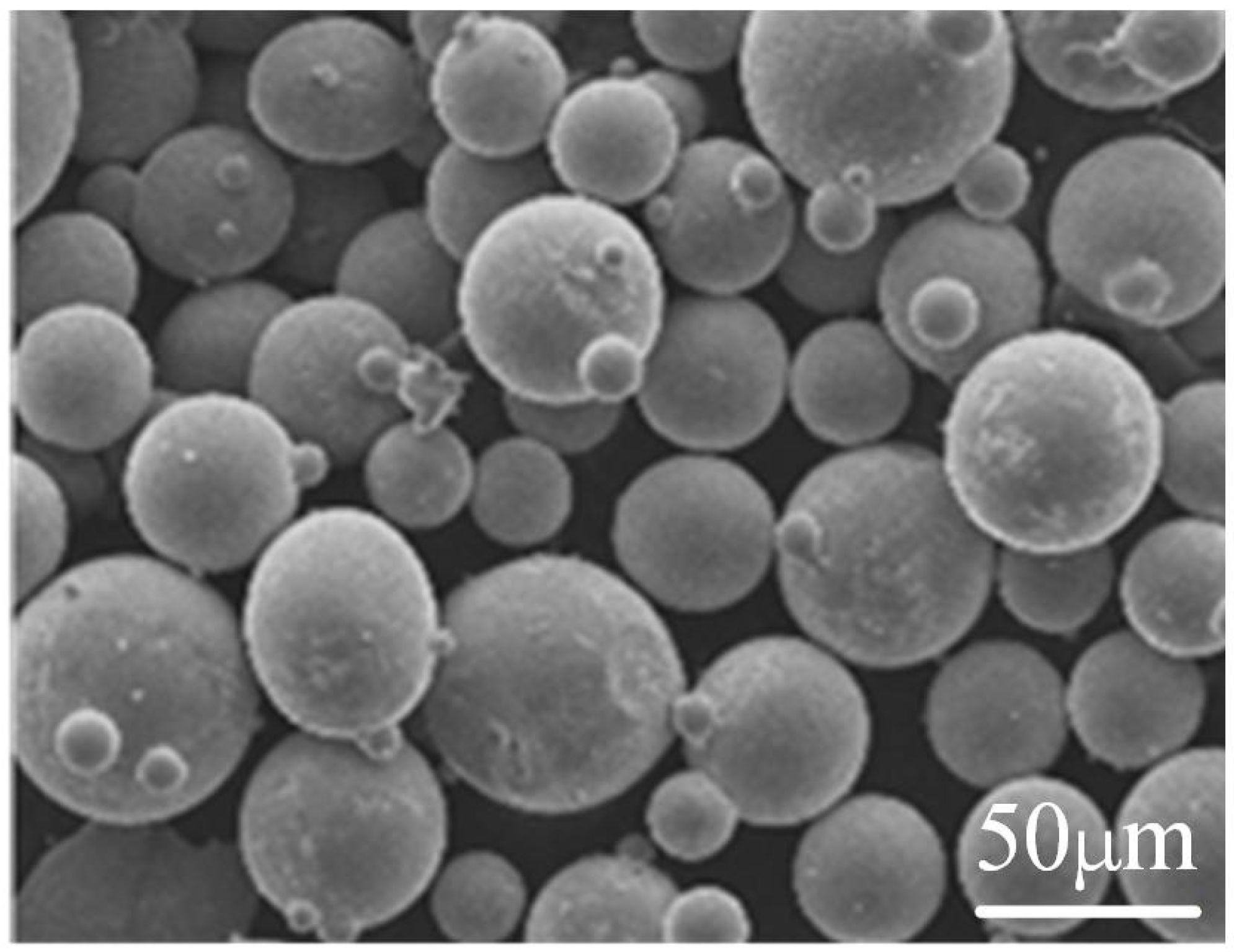
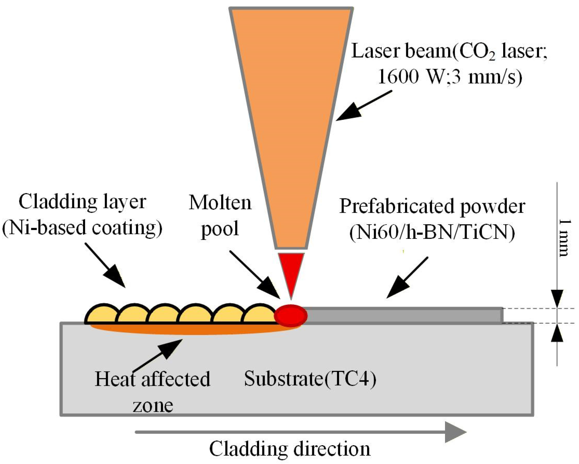
The cladding powders were Ni-based alloy powder, TiCN, and h-BN ceramic materials (Qinghe County Chuangying Metal Materials Co., Ltd., Xingtai, China). The chemical composition of the Ni-based alloy powder (mass fraction, wt.%) is as follows: 1.0% C, 4.0% B, 4.0% Si, 15.0% Cr, 2.0% Fe, and the balance Ni (74.0 wt.%). The SEM image of Ni-based alloy powder is shown in Figure 1. The particle size of the powder is 10–78 μm. The TiCN powder is blocky with a particle size of 2–3 μm. The h-BN powder is flake-like with a particle size of 3–7 μm. Drying treatment was carried out before the experiment to prevent the presence of moisture in the powder from affecting the experimental results. The powder was placed in a vacuum drying oven for 2 h at a temperature of 120 °C. As shown in Figure 2, it illustrates the schematic diagram of the cladding layer, laser beam, and prefabricated powder. The prefabricated powder was spread flat onto the substrate surface. First, a hollow polyethylene sheet with a thickness of 1 mm is placed on the surface of the substrate. Then, another polyethylene sheet is used to compact the powder and scrape off the excess powder.

2.2. Experimental Design

As the main research object, the experimental scheme of different h-BN powder ratios was designed, as shown in Table 1. While the TiCN proportion was a constant 15%, h-BN was incorporated at additions of 0%, 2%, or 5%. The laser power was 1600 W, and the scanning speed was 3 mm/s. The spot diameter was 3 mm. The overlap rate was 30%. Those parameters were selected through numerical simulation of Ni-based alloy coating on the surface of TC4 substrate [23].
In this experiment, a DL-HL-T2000 CO2 laser(Shenyang DALU Laser Technology Co., Ltd., Shenyang, China) with a generation line of 10.6 μm, operating in continuous wave (CW) mode, i.e., not in pulsed mode, was employed. The ratio of the mixed gas was as follows: CO2:N2:Ar (0.048:3.7:0.31). The cladding sample was cut to a size of 10 × 10 × 10 mm. Subsequently, the cut samples were polished and etched using aqua regia, which has a composition of HCl:HNO3 (3:1). After etching the coating section for 15 s with aqua regia, yellow bubbles were generated, which were a mixture of nitrogen dioxide (NO2, reddish brown/yellow) and chlorine (Cl2, yellowish green). The corresponding chemical reaction, shown in Equations (1)–(3), is listed below. The sample was immediately washed with anhydrous ethanol and ultrasonically cleaned for 15 min. Anhydrous ethanol dissolved the organic matter by terminating the reaction; ultrasonic cleaning thoroughly removed the residue on the surface of the coating. This improved the accuracy of metallographic analysis and composition detection together. The microstructure in different positions of the coating was obtained by using a scanning electron microscope of the model TESCAN MIRA LMS (TESCAN MIRA, TESCAN, Brno, Czech Republic). The distribution of elements in the coating was analyzed by using an energy-dispersive spectrometer. The phases were detected by a TD-3500 X-ray diffractometer (Dandong Tongda Science and Technology Co., Ltd., Dandong, China). The Vickers hardness tester (HXD-1000TMC/LCD, Shanghai Optical Instrument Co., Ltd., Shanghai, China) was used to measure the hardness of the coating, with a test load of 200 gf for 15 s (Wuxi Meters Precision Technology Co., Ltd., Wuxi, China). The friction and wear test was carried out on a MGW-02 high-speed reciprocating fatigue friction(Jinan YihuaTribology Testing Technology Co., Ltd., Jinan, China) and wear tester. The grinding ball material was GCr15. The frequency was 2 Hz. The loading was 10 N. The friction time was 20 min. The friction mode was dry sliding friction of a non-lubricated plane-spherical surface.
2 HNO 3 + 2 HCl 2 NO 2 + Cl 2 +   2 H 2 O
Fe +   2 HNO 3 + 6 HCl H 2 FeCl 4 + 2 NO 2 +   4 H 2 O
Ni +   2 HNO 3 + 4 HCl H 2 NiCl 4 + 2 NO 2 +   2 H 2 O

3. Results and Discussion

3.1. Phases

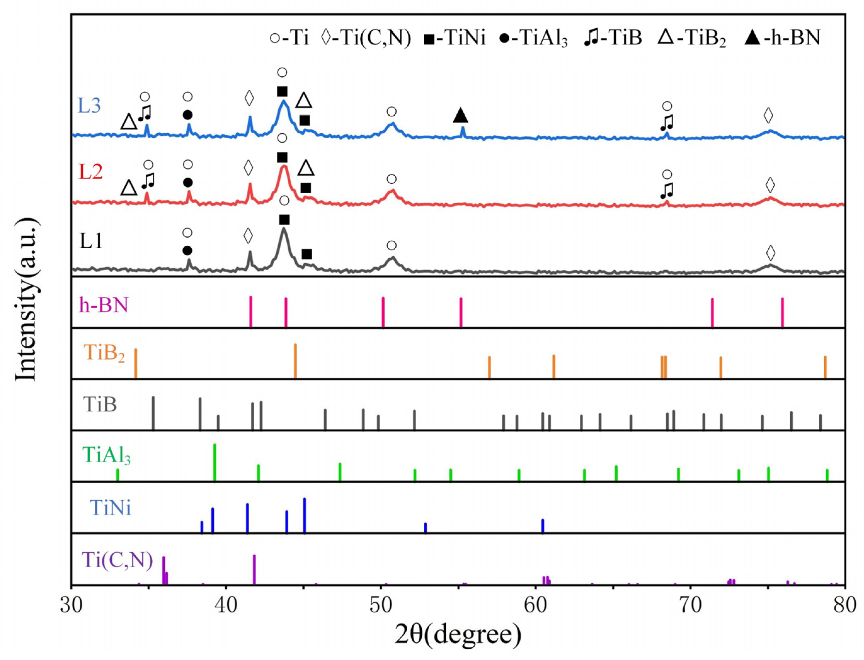
Figure 3 presents the X-ray diffraction patterns of the L1–L3 coatings, revealing their phase compositions and standard peaks of the phases. It can be seen from the diagram that the phases of L1–L3 coatings were mainly composed of Ti, TiNi (PDF 27-0344), Ti(C, N) (PDF 85-1152), and TiAl3 (PDF 65-4505). When the content of h-BN was 2%, the TiB phase was increased in the L2 coating compared with the L1 coating. When the content of h-BN was 5%, compared with the L1 coating, the TiB (PDF 73-2148) and h-BN (PDF 34-0421) phases increased in L3 coating. The TiB phase was detected in L2 and L3 coatings. The peak value of the TiB phase increased with the increase in h-BN content. This phenomenon was attributed to the addition of h-BN. When the laser irradiation temperature reached 2500 °C [23], h-BN decomposed into B element and N element, as shown in Equation (4). The Ti element had a very high affinity with the B element. According to the thermodynamic analysis, the B element and the Ti element reacted to form TiB2 (PDF 75-0967), as shown in Equation (5). Although the location of the TiB2 phase can be detected in Figure 3, it is not very obvious due to its small amount. A possible reason for this is that during the laser cladding process, the Ti element rapidly reacted with the B element to form TiB2. However, due to the significant amount of Ti element released from the melting of the substrate in the molten pool, the Ti element subsequently interacted with the formed TiB2 to produce TiB, as shown in Equation (6). As the h-BN content increased, the h-BN phase was detectable in the L3 coating containing 5% h-BN. This was attributed to the presence of undecomposed h-BN in the coating, resulting from the elevated h-BN content. In summary, the addition of h-BN led to the formation of both TiB and h-BN phases within the coating, with the peak intensity of TiB gradually increasing as the h-BN content rose. The TiB hard phase formed within the coating enhances the microhardness of the coating, while the self-lubricating properties of h-BN contribute to improving the wear resistance [24].
h - BN + laser   energy N + B
Ti + 2 B TiB 2
Ti + TiB 2 2 TiB

3.2. Microstructure

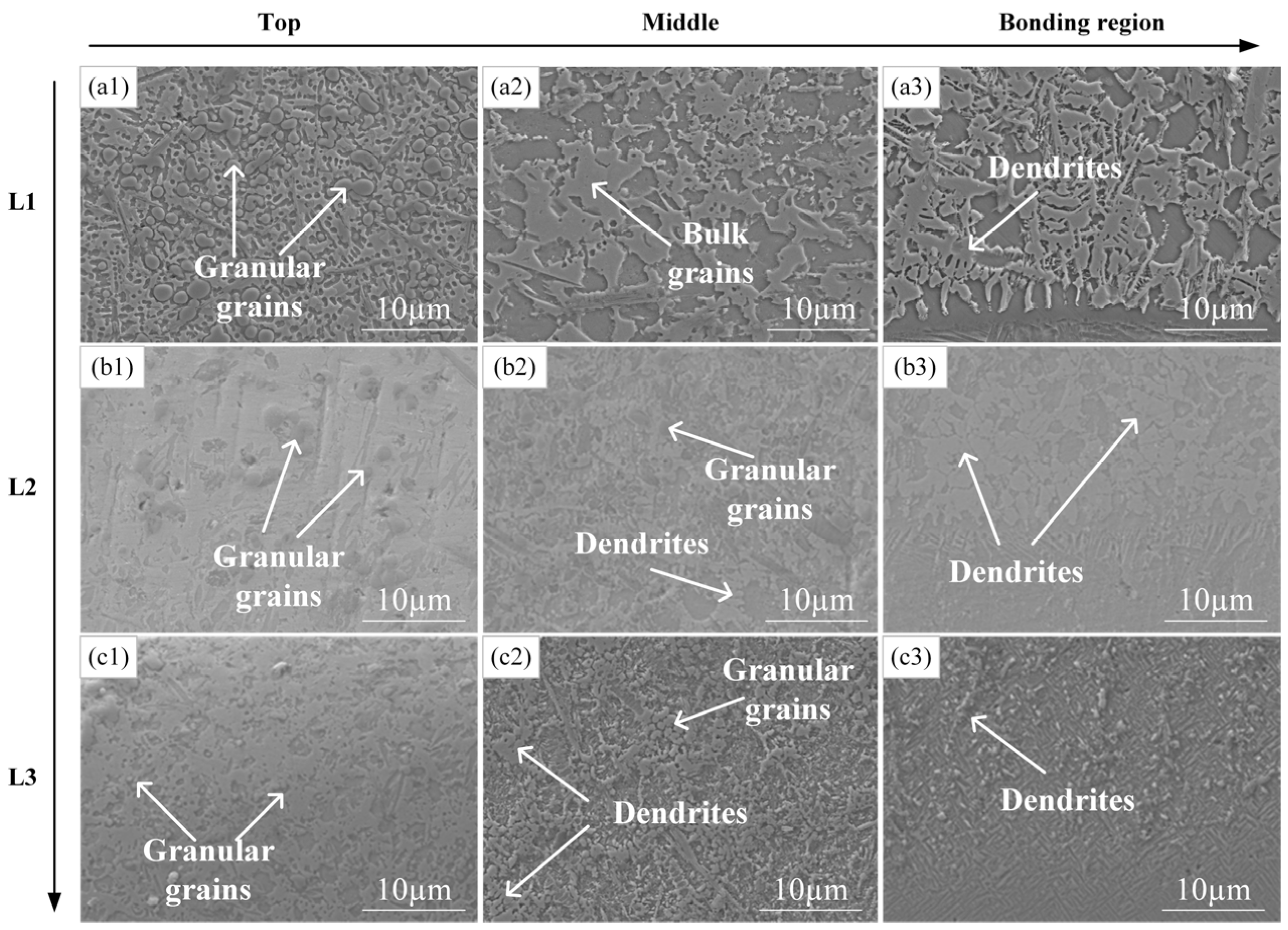
Figure 4 presents the SEM images of the top, middle, and bonding regions of the L1–L3 coatings, where the bonding region refers to the transition region formed by metallurgical bonding between the cladding layer and TC4 substrate during the laser cladding process. Specifically, in Figure 4(a1–a3), which depicts the L1 coating with 15% TiCN addition, it is observable that numerous granular grains are present at the top region, bulk grains dominate the middle region, and dendrites are evident in the bonding region. In the bonding region, due to the direct contact between the bottom of the coating and the substrate, the initial temperature gradient is large, and the solidification rate is low. So the G/R ratio is extremely high. With the passage of the liquid–solid interface, the temperature gradient decreases and the solidification rate increases. The undercooling of the composition makes the crystal form easy to transform into dendrites. In Figure 4(b1–b3), which shows the L2 coating with 15% TiCN and 2% h-BN additions, it was observed that the grain size in the top region was smaller compared to that of the L1 coating. The remaining micro-morphological features remained largely unchanged. The top region of the coating consisted of granular grains, the middle region consisted of granular grains and dendrites, and the bonding region was composed of dendrites. In the middle region, as the liquid–solid interface advances, the temperature gradient (G) decreases. The solidification rate (R) accelerates, and the heat dissipation conditions are complex. The component undercooling increases, which is beneficial to the formation of dendrites. In Figure 4(c1–c3), depicting the L3 coating with 15% TiCN and 5% h-BN additions, the top region was composed primarily of granular grains. The middle region featured a mixture of granular grains and dendrites, while the bonding region was mainly dendritic with some granular grains interspersed. The dendrite size was more refined than that of the L2 coating. This showed that with the addition of h-BN, the dendrites in the coating were gradually refined.
With the increase in h-BN content, the amount of TiB increased significantly, which was caused by the increased nucleation of TiB [25]. As a hard phase, the nucleation and growth of TiB could consume the energy in the molten pool, thereby inhibiting the coarse growth of other grains and leading to grain refinement. In the middle region, granular grains were formed by the nucleation of h-BN or TiB. Additionally, h-BN can easily cause local supercooling due to its high thermal conductivity (286.6 W·m−1·K−1) [26] and promote the formation of dendrites in L2 and L3. There were dendrites in the bonding regions of the L1–L3 coatings that were obviously different from those in the microstructure of the top and middle regions of the coatings. During the process of laser cladding, with the increase in temperature, the temperature gradient G gradually decreased at the bottom of the molten pool. As the crystallization rate R gradually increased, the G/R ratio decreased, which was conducive to the growth of dendrites. The grain size in Figure 4, measured by ImageJ 1.54p, is presented in Table 2 for the top, middle, and bonding regions of the L1–L3 coatings. The grain size progressively diminished at the top, middle, and bonding regions with the increasing h-BN content, with the L3 coating containing 5% h-BN exhibiting the smallest grain size. Thus, the addition of h-BN led to a gradual refinement of the coating’s microstructure, with the degree of refinement intensifying as the h-BN content increased.

3.3. Element Distribution

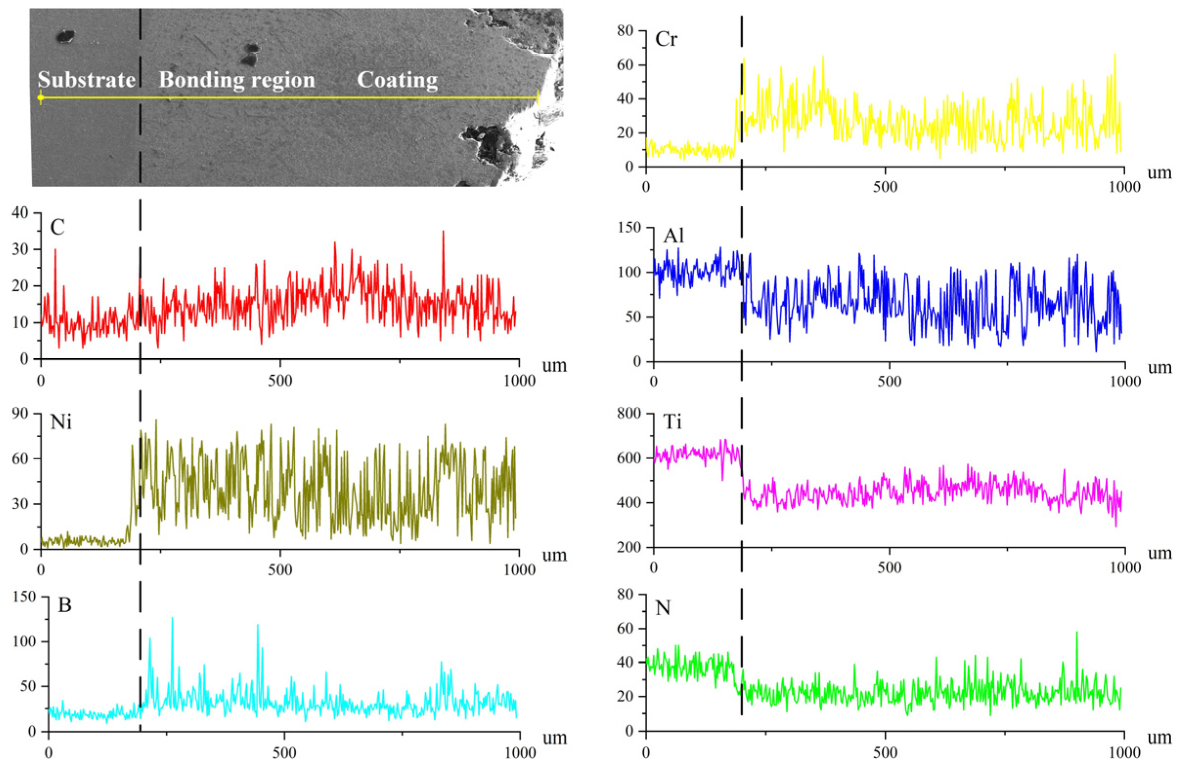
To further investigate the distribution of elements in the Ni-based composite coating after the addition of h-BN, an energy spectrometer was used to detect the element content in a specific area of the coating. Due to the dense microstructure of the L3 coating, the mechanical properties of the coating were good. Its microstructure and morphology were quite different from those of the L1 coating, so the L3 coating was selected for EDS line scanning. For analysis, Ti, Al, Ni, B, C, Cr and N elements were selected. The EDS line scan results, which display the relative signal intensity (CPS) of selected elements, are shown in Figure 5. These elements were detected in the coating region, bonding region, and substrate. The Ti element present in the substrate diffused into the coating, while the Ti element within the coating was uniformly distributed.
At the junction of the bonding region, it was observed that, from the substrate to the coating region, the Ti and Al elements exhibited a significant decrease, while the Ni element showed a significant increase. Additionally, the B element displayed multiple peaks in both the coating and bonding regions.
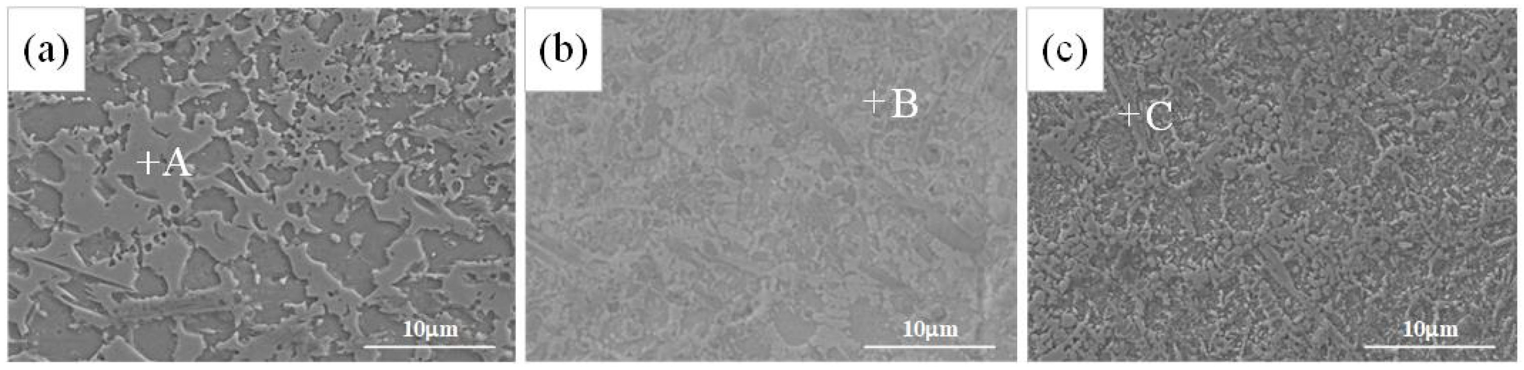
Due to the most significant changes in crystal structure occurring in the middle region of the L1–L3 coating, several positions in this area were selected for EDS point scanning analysis. As shown in Figure 6, in order to study the change in elements after adding h-BN, block grain G, granular grain H, and fine needle grain I were selected for EDS point scanning analysis. In the analysis, the elements of Ti, Ni, Al, Cr, C, B, and N were focused on. Their distribution in the selected grains was analyzed. The detailed EDS point scanning results for the different phases are listed in Table 3.
According to the EDS point scanning results, it was inferred that the bulk grain A was mostly composed of Ti, N, C, and other elements. The atomic ratio of Ti, C, and N was close to 2:1:1, and it was mainly composed of Ti, C, and N compounds. The granular grain B contained Ti and C elements, with an atomic ratio of approximately 1:1. Combined with the Ti(C, N) phase shown in the XRD test results, we speculate that the original Ti(C, N) may decompose or segregate during the coating preparation or cooling process, resulting in the formation of a TiC separated phase in the local area. The fine needle-like grain C was primarily composed of Ti and B elements, with an atomic ratio of approximately 1:1. Based on the XRD results, the grain was inferred to be TiB. The fine needle-like grain C was primarily composed of Ti and B elements, with an atomic ratio of approximately 1:1. Based on the XRD results, the grain was inferred to be TiB. As the amount of h-BN increased, the number of fine needle-like TiB grains within the coating gradually increased, resulting in a uniform distribution throughout the coating. This enhancement contributed to an improvement in both the microhardness and wear resistance of the coating.
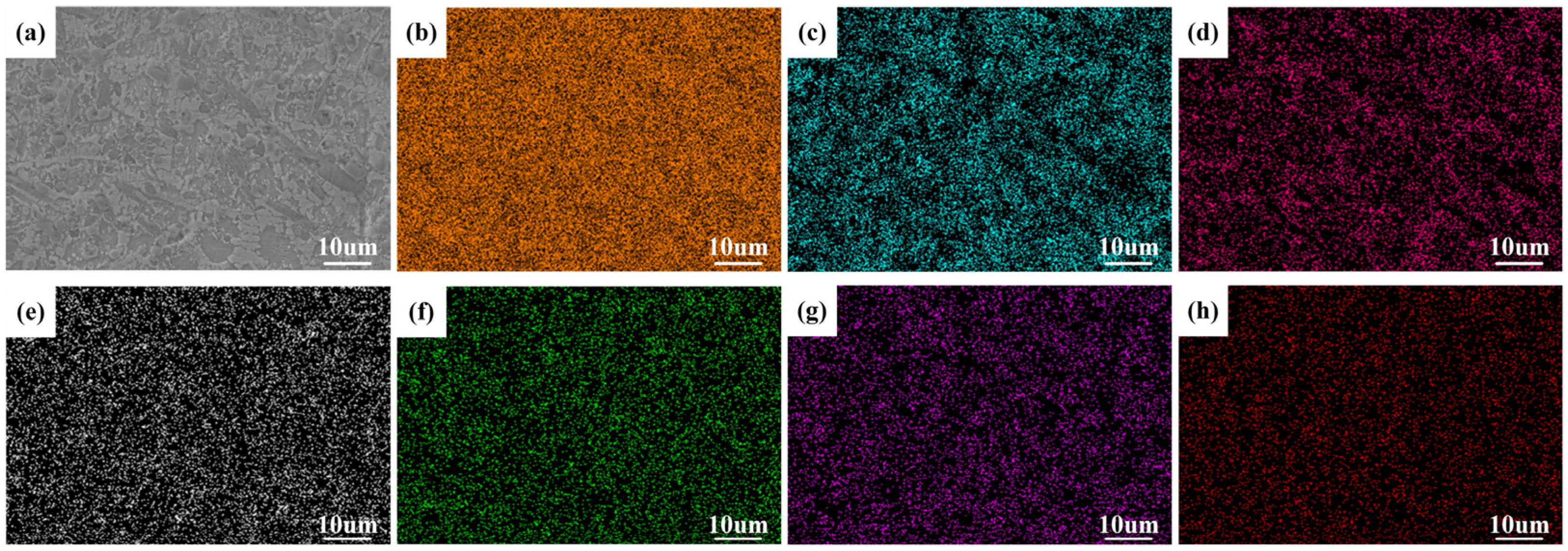
Figure 7 shows the SEM image and EDS element distribution in the middle of the L2 coating. The image reveals some elements, such as Ti, C, and N, present in both the dendritic and granular grain structures. A large amount of Ni element was present in the boundary part of the dendrite, while the remaining elements, such as Ti, Cr, and B, were mostly dispersed throughout the coating.
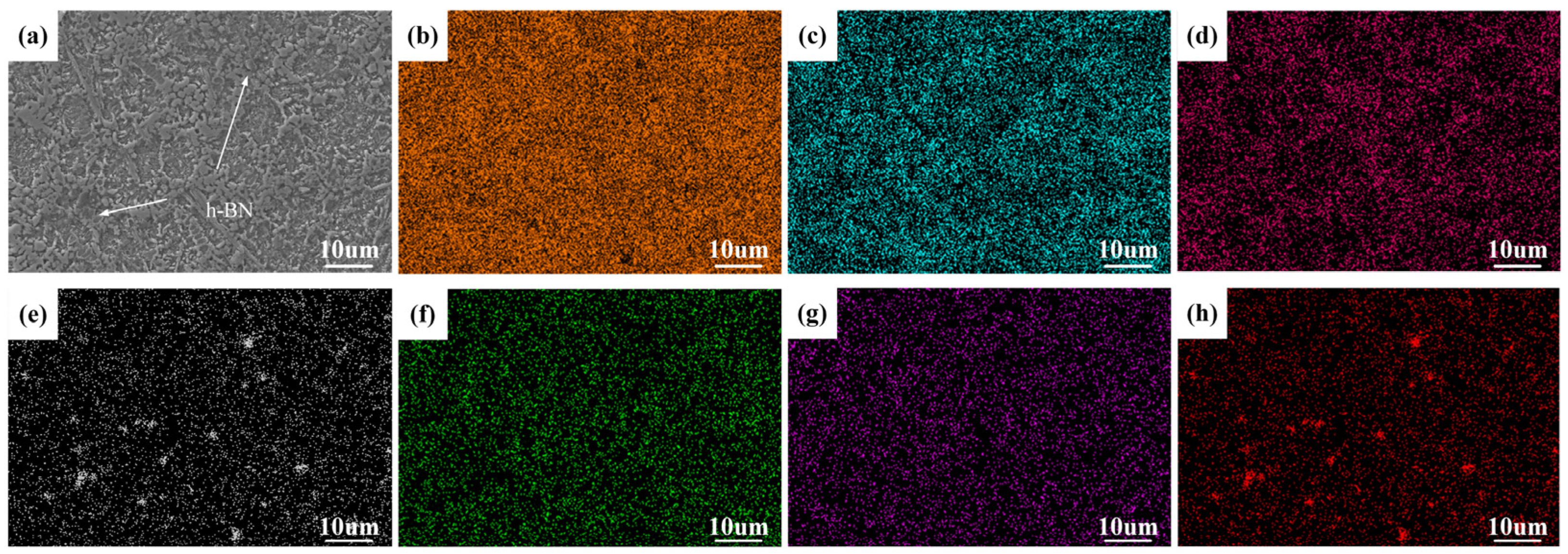
Figure 8 shows the SEM image and EDS element distribution in the middle region of the L3 coating. It can be seen from the image that the element distribution was similar to that of the L2 coating. However, upon observing the distribution of B and N elements, it was evident that there was an elemental enrichment phenomenon, which is more than the L2 coating. This enrichment was attributed to the different melting points of Ni-based powder and h-BN during the laser cladding process. The melting point of h-BN was much higher than that of the Ni-based powder. The Ni-based powder was first heated to the melting point. Then, the unmelted h-BN was brought into the molten pool under the stirring of the alloy solution tension. During the rapid cooling process of the molten pool, the unmelted h-BN particles served as heterogeneous nucleation sites, promoting the rapid growth of crystals and resulting in the appearance of h-BN particles in the coating.
When h-BN was added to the coating, it resulted in the formation of diffuse TiB and a small amount of TiC hard phases. Additionally, undecomposed h-BN was detected in the 5% h-BN coating, which contributed to an enhancement in the microhardness and wear resistance of the coating.

3.4. Microhardness

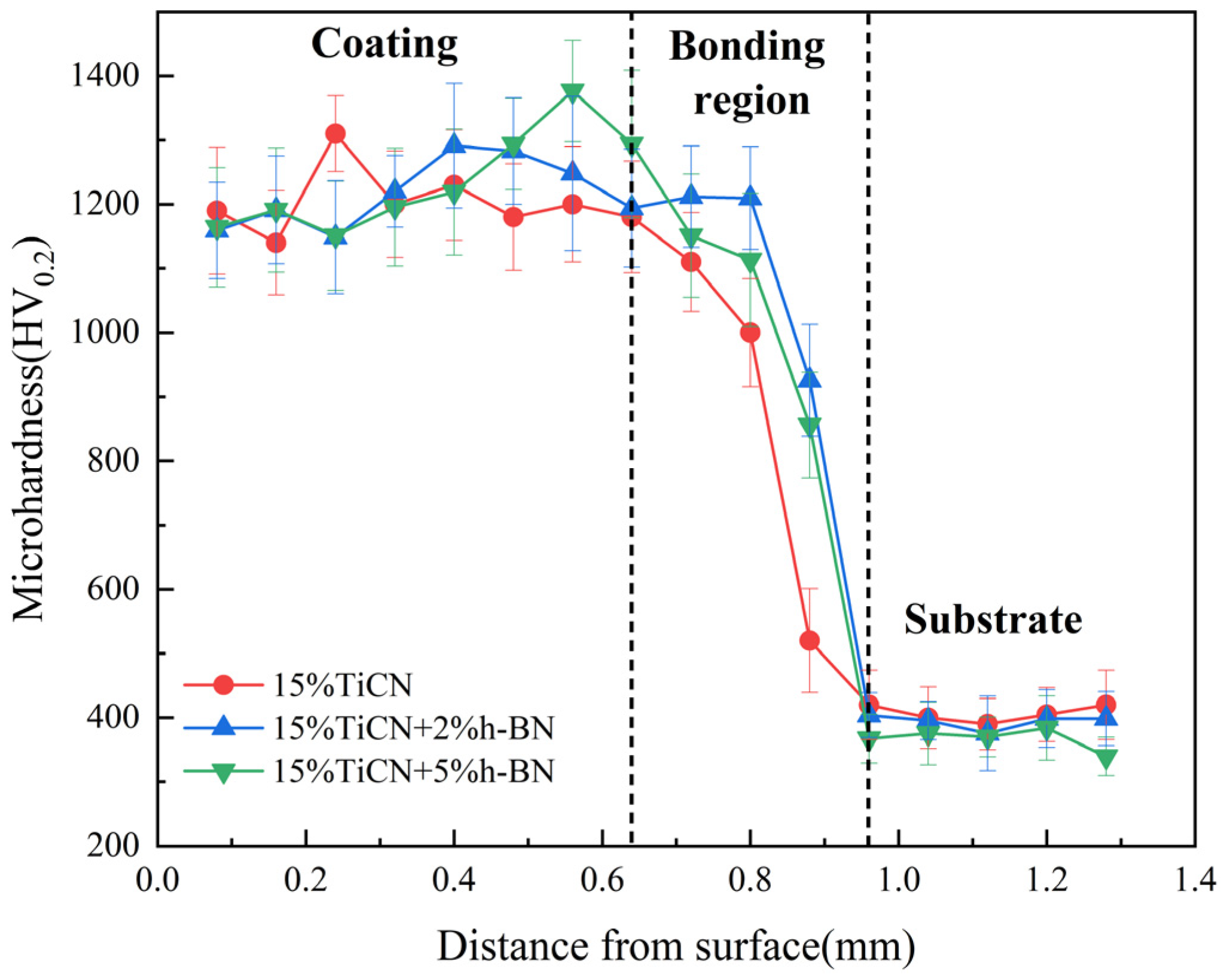
Figure 9 shows the microhardness curves of Ni-based composite coatings with different TiCN/h-BN contents. From left to right, it corresponds to the microhardness values of the coating region, the bonding region, and the substrate of L1–L3, respectively. The microhardness changes observed in all three groups of samples followed a similar trend, with an initial increase followed by a decrease. Among them, the coating region exhibited the highest microhardness, while the bonding region showed a downward trend.
Table 4 shows the average microhardness of Ni-based composite coatings with varying TiCN/h-BN contents. According to the table, the L1, L2, and L3 coatings exhibited average microhardness values of 1203.8, 1216.8, and 1235.5 HV0.2, respectively, with the L3 coating exhibiting the highest average microhardness. As the h-BN content increased, the microhardness of the Ni-based composite coating exhibited a slight increase. As the amount of h-BN increased, the quantity of the TiB hard phase in the coating rose, resulting in an enhancement of the coating’s microhardness. From a microstructure point of view, since the dendrites in the coating were gradually decomposed into fine dendrites and granular grains, the hardness of the coating was negatively correlated with the grain size. According to the Hall-Petch Formula (7) [27], the finer the microstructure of the coating, the higher its strength. Additionally, as the h-BN content increased, undissolved h-BN particles began to appear within the coating. During the solidification process of the molten pool, these undecomposed h-BN were used as heterogeneous nucleation sites for grain growth, thereby increasing the nucleation rate of TiC and TiB phases. This refinement of the coating structure achieved the effect of fine-grain strengthening, ultimately enhancing the microhardness of the coating.
Hall-Petch formula:
σ y = σ 0 + k d 1 / 2
where σy is the yield limit of the material; σ0 is the lattice friction resistance when moving a single dislocation; k is a constant; d is the average grain size.

3.5. Friction and Wear

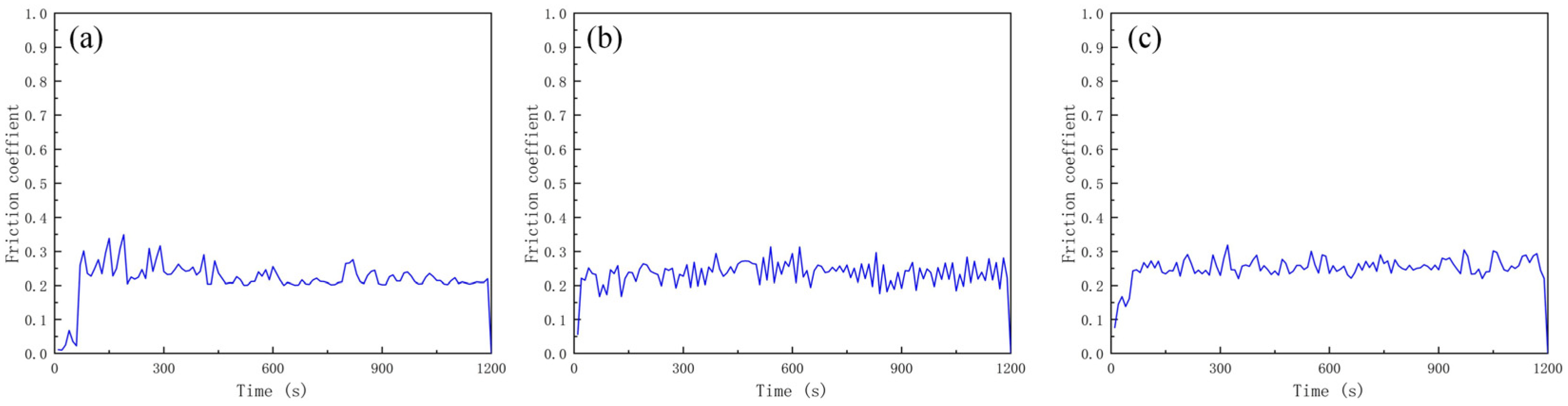
Figure 10 shows the friction coefficient curves of Ni-based composite coatings with varying TiCN/h-BN contents. From the figure, it is evident that the friction coefficient of the coating initially increased rapidly before gradually stabilizing. During the stable period, the friction coefficient fluctuated within a certain range, but generally tended to be stable. From Figure 10a–c, it can be seen that the friction coefficient curves of L1–L3 coatings fluctuate within a certain range. After the addition of h-BN, the fluctuation in the friction coefficient of the L2 and L3 coatings decreased. In summary, as the h-BN content increased, the friction coefficient curve became more stable. As the content of h-BN increased, the amount of undissolved h-BN also rose. This led to a more stable friction and wear coefficient curve due to the self-lubricating properties of h-BN.
Table 5 shows the average friction coefficient of L1–L3 coatings. It can be seen that the average friction coefficients of L1–L3 coatings were 0.186, 0.178, and 0.164, respectively. After incorporating h-BN into the coating, the friction and wear coefficient decreased markedly. Furthermore, as the content of h-BN increased, the friction and wear coefficient exhibited a downward trend. Among them, the L3 coating had the lowest friction coefficient. The average friction coefficient is a direct reflection of wear resistance during the friction process. The lower the friction coefficient, the smaller the friction force, and the lower the heat and mechanical stress generated, which can reduce the thermal softening, plastic deformation, and crack propagation of the coating surface, thereby delaying the wear process.
The wear resistance of laser cladding coatings refers to the inherent ability of the coating to resist material removal, surface damage, and dimensional loss when it is subjected to relative sliding under specific service conditions. It is a core performance indicator for evaluating the service life and reliability of laser cladding coatings in wear-prone engineering applications. In Table 6, the wear volumes of L1–L3 coatings are 0.098, 0.094 and 0.086 mm3, and the wear rate of L1–L3 coatings are 4.06, 3.79 and 3.66 × 10⁻⁵ mm3·N−1·m−1, respectively. When the content of h-BN is 5%, the wear rate of L3 coating is 3.66 × 10⁻⁵ mm3·N−1·m−1. Compared with the wear rate of 6.98 × 10⁻⁵ mm3·N−1·m−1, the wear resistance of L3 coating is 47.6% higher than that of the substrate. The formula for wear rate is shown in Formula (8) [27]. After the addition of h-BN to the coating, the wear volume decreased significantly. The wear volume decreased with the increase in h-BN content. Among them, the L3 coating had the smallest wear volume. The above analysis showed that after the addition of h-BN, the wear resistance of the coating was improved to varying degrees. The wear resistance continued to increase with the increase in h-BN content. The reason was that, in terms of the microstructure of the coating, the addition of h-BN changed the microstructure of the coating. The dendrites in the coating gradually decomposed into fine dendrites and granular grains. The microstructure of the coating became refined, resulting in an increase in the microhardness of the coating. In general, there was a linear relationship between the microhardness and wear resistance of the coating. The greater the microhardness, the better the wear resistance. In terms of the element distribution of the coating, after the addition of h-BN, a dispersed TiB and a small amount of TiC hard phase were formed in the coating, which reduced the wear loss during the wear process. With the increase in h-BN content, un-decomposed h-BN appears in the coating. The h-BN has self-lubrication properties, which also reduce the wear loss.
Wear rate formula:
w = v F L
where w is the wear rate (mm3·N−1·m−1); v is the wear volume loss (mm3); F is the applied normal load (N); L is the sliding distance (m).
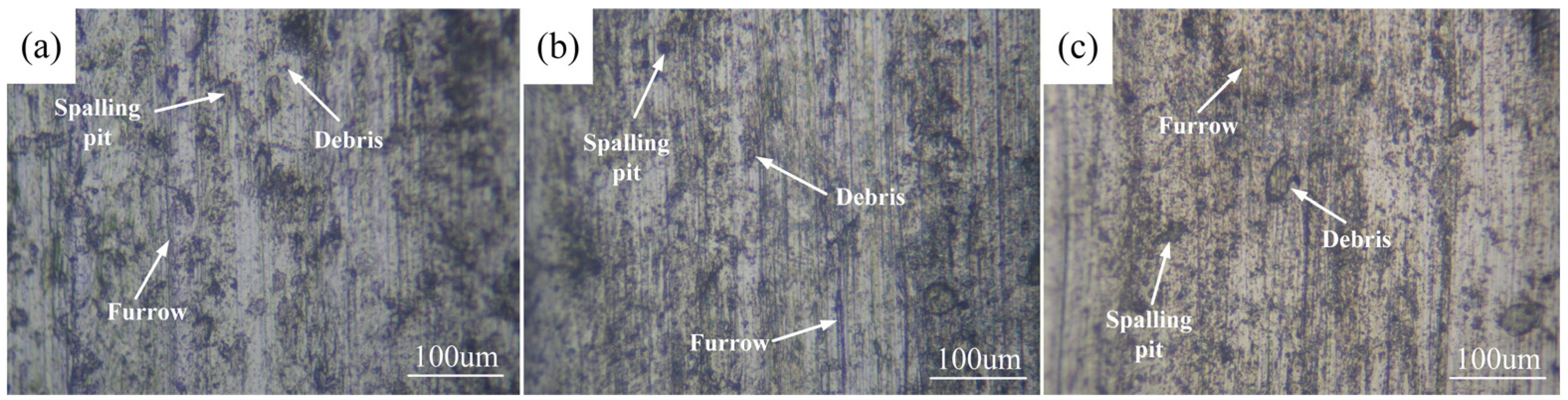
Figure 11 shows the wear morphology of L1–L3 coatings. The wear surface of the coatings developed furrows along the direction of friction, accompanied by varying degrees of spalling. In Figure 11a–c, as the amount of h-BN increased, the spalling phenomenon on the wear surface of the L1 to L3 coatings gradually decreased. Their wear morphology became smoother. And the furrows shallowed. The wear mechanism of the L1–L3 coatings was mainly abrasive wear. In summary, after the addition of h-BN, the wear volume decreased and the wear resistance of the coating increased. As the content of h-BN increased, the wear resistance of the coating gradually improved. The wear resistance of the L3 coating was the best.

4. Conclusions

(1)
The phases of the L1–L3 coatings were mainly composed of Ti, TiNi, Ti(C, N), and TiAl3. After the addition of h-BN, the TiB phase was detected in L2 and L3 coatings. The peak intensity of the TiB phase gradually increased with the increase in h-BN content. The TiB reinforcement phase in the coating existed in the form of fine needles, while the TiC reinforcement phase existed in the form of particles.
(2)
With the increase in h-BN content, the average microhardness of Ni-based composite coatings increased gradually. Among them, the L3 coating had the highest microhardness of 1235.5 HV0.2. With the increase in h-BN content, the microstructure of the coating was gradually refined. The L3 coating had the smallest grain size. The original dendritic structure was gradually decomposed and transformed into white granular TiB.
(3)
The wear volumes of L1–L3 coatings were 0.098, 0.094 and 0.086 mm3, respectively. With the increase in h-BN content, the wear volume showed a downward trend. Among them, the L3 coating had the smallest wear volume. In terms of coating microstructure, the amount of TiB increased obviously, and its growth consumed the energy in the molten pool and inhibited the coarse growth of other grains, thus refining the grains. In terms of the distribution of coating elements, some TiB and a small amount of TiC hard phase formed. These hard phases and undecomposed h-BN together reduced the wear loss during the wear process.

Author Contributions

Conceptualization, Y.L. and G.L.; methodology, Z.Z.; software, Y.L.; validation, R.X., H.L. and N.M.; formal analysis, Y.L.; investigation, R.X.; resources, Z.Z.; data curation, H.L.; writing—original draft preparation, Y.L.; writing—review and editing, Y.L.; visualization, N.M.; supervision, Y.L.; project administration, Z.Z.; funding acquisition, Y.L. and Z.Z. All authors have read and agreed to the published version of the manuscript.

Funding

We would like to acknowledge financial support from Jiujiang Key Research and Development Program (2025_001106), 2024 Key Research Platforms and Projects for Universities in Guangdong Province (2024KCXTD073), 2024 University Research Project of Guangzhou Education Bureau (2024312005), Guangdong Provincial Science and Technology Innovation Fund Projects (SDZX2023016, SDZX2023017), Yangjiang Alloy Materials and Hardware Knives and Scissors Key Industry Talent Revitalization Plan Special Foundation (RCZX2025018), 2025 Guangzhou Municipal Teaching Reform Project for Higher Education (2025JXMS002), Guangdong Educational Science Planning Project (2023GXJK843, 2022GXJK546).

Institutional Review Board Statement

Not applicable.

Informed Consent Statement

Not applicable.

Data Availability Statement

Data are contained within the article.

Conflicts of Interest

Author Ruoyu Xu was employed by the company Daqing Oilfield Perforating Equipment Co., Ltd. Authors Hui Liang and Nan Ma were employed by the company Daqing Oilfield Powerlift Industry Co., Ltd. The remaining authors declare that the research was conducted in the absence of any commercial or financial relationships that could be construed as a potential conflict of interest.

References

  1. Xu, S.; Han, K.; Wang, H.; Xi, Y.; Wang, L.; Dong, X. The Influence of Adding B4C and CeO2 on the Mechanical Properties of Laser Cladding Nickel-Based Coatings on the Surface of TC4 Titanium Alloy. Materials 2024, 17, 3823. [Google Scholar] [CrossRef] [Scilit] [PubMed]
  2. Tian, Y.; Pang, M.; Ji, F. Study on the impact of laser power variation on the performance of Ti-6Al-4V coating by laser cladding on HT250. Opt. Laser Technol. 2024, 175, 110809. [Google Scholar] [CrossRef] [Scilit]
  3. Liu, X.; Jiang, F.; Chen, Z.; Dong, W.; Jiang, G.; Dong, T.; Sun, W.; Liu, L.; Guo, C. Microstructure and corrosion property of TC4 coating with Al0.5CoCrFeNi high-entropy alloy interlayer by laser cladding. Surf. Coat. Technol. 2024, 476, 130190. [Google Scholar] [CrossRef] [Scilit]
  4. Zhang, H.; Huang, H.; Wang, C.; Zhang, H.; Wu, H. Understanding the micro-deformation behavior of the FeCoCrMnNi high-entropy alloy during vibration-assisted scratching. Tribol. Int. 2026, 217, 111662. [Google Scholar] [CrossRef] [Scilit]
  5. Ghorashi, M.; Farrahi, G.; Movahhedy, M. Considering cyclic plasticity to predict residual stresses in laser cladding of Inconel 718 multi bead samples. J. Manuf. Process. 2019, 42, 149–158. [Google Scholar] [CrossRef] [Scilit]
  6. Singh, J.; Thakur, L.; Angra, S. An investigation on the parameter optimization and abrasive wear behaviour of nanostructured WC-10Co-4Cr TIG weld cladding. Surf. Coat. Technol. 2020, 386, 125474. [Google Scholar] [CrossRef] [Scilit]
  7. Reddy, L.; Preston, S.; Shipway, P.; Davis, C.; Hussain, T. Process parameter optimisation of laser clad iron based alloy: Predictive models of deposition efficiency, porosity and dilution. Surf. Coat. Technol. 2018, 349, 198–207. [Google Scholar] [CrossRef] [Scilit]
  8. Sun, R.; Niu, W.; Wang, C. Microstructure and Wear Resistance of TiN-NiCrBSi Laser Clad Layer on Titanium Alloy Surface. Rare Met. Mater. Eng. 2007, 36, 7–10. [Google Scholar]
  9. Chen, T.; Wu, F.; Wang, H.; Liu, D. Laser Cladding In-Situ Ti(C, N) Particles Reinforced Ni-Based Composite Coatings Modified with CeO2 Nanoparticles. Metals 2018, 8, 601. [Google Scholar] [CrossRef] [Scilit]
  10. Niu, W.; Sun, R. Effect of h-BN Content on Microstructures and Wear Resistance of Laser Cladding Self-lubricant Coatings. Chin. J. Lasers 2011, 38, 126–132. [Google Scholar]
  11. Chen, Y.; Xu, Y.; Li, T.; Du, J.; Guo, L.; Hu, K. Fabrication and characterization of self-lubricating anti-wear 316L stainless steel/h-BN composite coatings on Q235 substrate via laser cladding. Opt. Laser Technol. 2025, 180, 111564. [Google Scholar] [CrossRef] [Scilit]
  12. Kumar, V.; Rakshit, R.; Das, A. Mechanical and tribological performance of fiber laser cladded h-BN + SS316 composite on SS316 surface. J. Mater. Process. Technol. 2018, 278, 116509. [Google Scholar] [CrossRef] [Scilit]
  13. Cai, Q.; Li, G.; Wu, B.; Xu, S.; Wang, L.; Guo, Y. Effect of TiC content on microstructure and properties of TiC/Ni60 coatings on Ti6Al4V alloy deposited by laser cladding. Opt. Laser Technol. 2024, 168, 109854. [Google Scholar] [CrossRef] [Scilit]
  14. Ertekin, N. Nano-electro-mechanical conduct of boron nitride nanotube as piezoelectric nanogenerators and nanoswitches. Smart Mater. Struct. 2024, 33, 025037. [Google Scholar] [CrossRef] [Scilit]
  15. Duan, X.; Yang, Z.; Wang, Y.; Chen, L.; Tian, Z.; Cai, D.; Jia, D.; Zhou, Y. Research and Application Progress of Hexagonal Boron Nitride (h-BN) Based Composite Ceramics. Prog. Mater. China 2015, 34, 770–782. [Google Scholar]
  16. Ren, J.; Liu, X.; Yu, P.; Lu, X.; Chen, Y.; Shi, G.; Wu, S.; Xu, D. Effect of Normal Load on Tribological Properties of Ni60/h-BN Self-Lubricating Anti-Wear Composite Coating on Ti6Al4V Alloy by Laser Cladding. Tribology 2015, 35, 407–414. [Google Scholar]
  17. Behera, B.; Sahu, K.; Choudhury, A. Effect of processing parameters on Tribo-mechanical properties of developed Nano-Composite Coating of h-BN & B4C on Ti6Al4V Substrate by Laser Surface Alloying. Adv. Mater. Process. Technol. 2022, 8, 3934–3949. [Google Scholar]
  18. Liu, K.; Yan, H.; Zhang, P.; Zhao, J.; Yu, Z.; Lu, Q. Wear Behaviors of TiN/WS2+hBN/NiCrBSi Self-Lubricating Composite Coatings on TC4 Alloy by Laser Cladding. Coatings 2020, 10, 747. [Google Scholar] [CrossRef] [Scilit]
  19. Miah, M.; Chand, D.; Malhi, G.; Wang, G. Influence of scanning speed on titanium alloy processed with TC4+Ni60/hBN composite powder by laser metal deposition coating technology. Aircr. Eng. Aerosp. Technol. 2024, 96, 643–654. [Google Scholar] [CrossRef] [Scilit]
  20. Zhang, T.; Aihemaiti, H.; Jeong, I.; Liu, Y. In situ Ti2Ni/Ti2S reinforced Ti-based composites with enhanced mechanical properties fabricated by laser cladding on TC4 alloy. Mater. Lett. 2023, 338, 134044. [Google Scholar] [CrossRef] [Scilit]
  21. Xia, S.; Wu, M.; Ma, Y.; Chen, C. Effect of TiC content on microstructure and properties of laser clad layer on TC4 alloy. Heat Treat. Met. 2020, 45, 212–215. [Google Scholar]
  22. Miah, M.; Chand, D.; Malhi, G.; Khan, S. Influence of laser scanning power on microstructure and tribological behavior of NI-composite claddings fabricated on TC4 titanium alloy. Aircr. Eng. Aerosp. Technol. 2023, 95, 1165–1171. [Google Scholar] [CrossRef] [Scilit]
  23. Liu, Y.; Liu, X.; Xu, Z.; Yu, M. Numerical simulation and wear resistance property of Ni-based alloy coating on the surface of Ti-6Al-4V substrate. Lubricants 2023, 11, 513. [Google Scholar] [CrossRef] [Scilit]
  24. Zhou, D.; Sun, R. Effect of laser scanning rate on microstructure and properties of nickel-based h-BN composite coating. Heat Treat. Met. 2017, 42, 167–171. [Google Scholar]
  25. Li, M.; Huang, J.; Zhu, Y.; Li, Z.; Wu, Y. Effect of BN content on microstructure evolution and wear property of in situ Ti/(TiB+TiN) hybrid composite coating by laser cladding. Chin. J. Lasers 2015, 42, 94–99. [Google Scholar]
  26. Niu, B.; Zhong, L.; Hao, W.; Yang, Z.; Duan, X.; Cai, D.; He, P.; Jia, D.; Li, S.; Zhou, Y. First-principles study of the anisotropic thermal expansion and thermal transport properties in h-BN. Sci. China Mater. 2020, 64, 953–963. [Google Scholar] [CrossRef] [Scilit]
  27. Zhang, D.; Li, H.; Jiang, J.; Wang, B. Effect of biomimetic unit structure on microstructure and properties of in-situ TiC-TiB2 enhanced nodular cast iron. Surf. Interfaces 2025, 72, 107151. [Google Scholar] [CrossRef] [Scilit]
Figure 1. SEM image of Ni-based alloy powder.
Coatings 16 00490 g001
Figure 2. Schematic diagram of cladding layer, laser beam, and prefabricated powder.
Coatings 16 00490 g002
Figure 3. XRD patterns of Ni-based composite coatings with different TiCN/h-BN contents and standard peaks of the phases.
Coatings 16 00490 g003
Figure 4. SEM images of the top, middle, and bonding regions of the coatings with different TiCN and h-BN contents: (a1a3) L1; (b1b3) L2; (c1c3) L3.
Coatings 16 00490 g004
Figure 5. SEM image and EDS line scan results of 15% TiCN + 5% h-BN Ni-based composite coating.
Coatings 16 00490 g005
Figure 6. SEM images of the middle of L1–L3 coatings: (a) L1; (b) L2; (c) L3.
Coatings 16 00490 g006
Figure 7. SEM image and EDS element distribution in the middle region of L2 coating: (a) SEM; (b) Ti; (c) Al; (d) Ni; (e) B; (f) C; (g) Cr; (h) N.
Coatings 16 00490 g007
Figure 8. SEM image and EDS element distribution in the middle region of L3 coating: (a) SEM; (b) Ti; (c) Al; (d) Ni; (e) B; (f) C; (g) Cr; (h) N.
Coatings 16 00490 g008
Figure 9. Microhardness changes of Ni-based composite coatings with varying TiCN/h-BN contents.
Coatings 16 00490 g009
Figure 10. Friction and wear coefficients of Ni-based composite coatings with varying TiCN/h-BN contents: (a) L1; (b) L2; (c) L3.
Coatings 16 00490 g010
Figure 11. The wear morphology of L1–L3 coatings: (a) L1; (b) L2; (c) L3.
Coatings 16 00490 g011
Table 1. Experimental scheme.
SampleLaser Power (W)Scanning Speed (mm/s)TiCN (wt.%)h-BN
(wt.%)
L116003150
L216003152
L316003155
Table 2. Grain size of the top, middle, and bonding regions in the L1–L3 coatings (μm).
SampleTop RegionMiddle RegionBonding Region
L10.92–3.72.3–9.5210.18–14.62
L21.18–2.171.4–7.528.16–10.52
L30.63–1.340.68–6.212.15–7.45
Table 3. EDS point scanning results of G-I points (At%).
Point Scanning Point SelectionTiNiAlCrCBN
Bulk grain A47.176.322.731.0321.730.5720.45
Granular grain B45.165.632.822.6538.180.245.32
Fine needle-like grain C39.117.533.170.449.0640.370.32
Table 4. Average microhardness of L1–L3 coatings.
SampleAverage Microhardness (HV0.2)Variance (HV0.22)
L11203.813.9
L21216.822.6
L31235.527.7
Table 5. Average friction coefficient of L1–L3 coatings.
SampleTiCN (wt.%)h-BN (wt.%)Average Friction CoefficientVariance
L11500.1862.67 × 10−6
L21520.1783.41 × 10−6
L31550.1643.22 × 10−6
Table 6. Wear scar length, width, wear volume, and wear rate of L1–L3 coatings.
SampleTiCN
(wt.%)
h-BN
(wt.%)
Wear Scar Length
(mm)
Wear Scar Width
(mm)
Wear Volume
(mm3)
Wear Rate
(×10−5 mm3·N−1·m−1)
L11505.030.910.0984.06
L21525.160.890.0943.79
L31554.890.880.0863.66
Disclaimer/Publisher’s Note: The statements, opinions and data contained in all publications are solely those of the individual author(s) and contributor(s) and not of MDPI and/or the editor(s). MDPI and/or the editor(s) disclaim responsibility for any injury to people or property resulting from any ideas, methods, instructions or products referred to in the content.