This study adopts a combined experimental–modeling approach to evaluate the fire performance, optical properties, environmental durability, and system-level fire implications of nano-clay-modified ethylene–vinyl acetate encapsulants for building-integrated photovoltaic applications [
5]. Photovoltaic-grade EVA was selected as the baseline encapsulation material, while MMT nano-clay was employed as a flame-retardant additive due to its high aspect ratio and favorable toxicological profile. EVA/MMT composites were prepared via melt-mixing to ensure industrial relevance and reproducibility, followed by compression molding into uniform sheets representative of photovoltaic encapsulant layers [
5].
2.2. Material Selection and Characterization
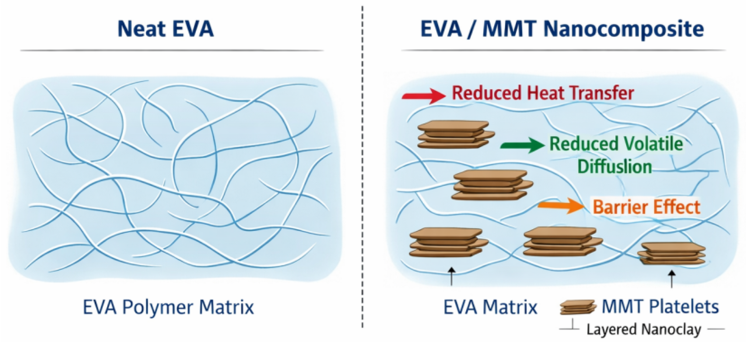
As shown in
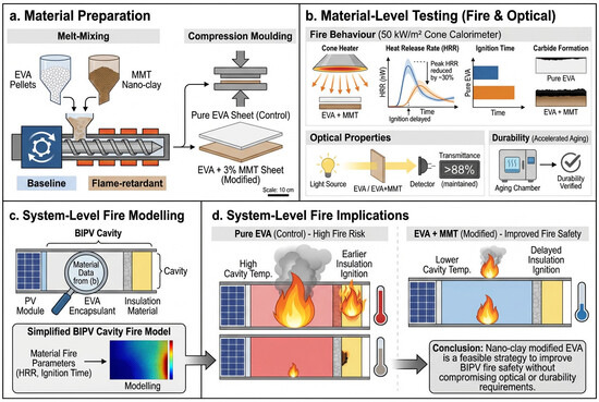
Figure 1, the addition of MMT introduces layered platelets into the EVA matrix. These platelets are expected to contribute to barrier formation during heating and combustion, thereby reducing heat transfer and slowing the release of volatile degradation products.
In this study, a total of three formulas were prepared and compared: pure EVA, EVA/3% MMT, and EVA/5% MMT. The content of 3% is regarded as a candidate formula for balancing BIPV, while the content of 5% is used as a comparative formula for higher loads to illustrate the impact of filler content on fire protection and optical properties. All the charts, tables and discussions have been revised accordingly to distinguish between the proposed formula and the exploratory comparison [
6].
Commercial-grade EVA particles used in photovoltaic packaging are used as substrates. High-purity sodium montmorillonite (Na-MMT) nanofiller is selected as a flame retardant. The addition of montmorillonite is fixed at 3% (mass fraction), which is the result of a balance between considering the improvement of flame-retardant performance and the optical performance requirements of photovoltaic applications.
2.2.1. EVA Substrate
The basic packaging material selected for this study is photovoltaic-grade ethylene–vinyl acetate. Due to its optical clarity, flexibility, adhesion to glass and silicon, and excellent processability, it is widely used in commercial photovoltaic module lamination. The EVA sheet used in this study contains 28%–33% vinyl acetate, which meets the industry standard of photovoltaic packaging.
The main physical and chemical properties of EVA include the following:
- 1.
Density: 0.94–0.96 g/cm3.
- 2.
Vitrification transition temperature (Tg): −30∼−10 °C.
- 3.
Melting point: 60–70 °C.
- 4.
Light transmittance: >90% in the visible light range.
- 5.
Thermal decomposition temperature: 300–330 °C.
It is well known that pure EVA undergoes multi-step decomposition, including deacetylation and chain fracture, which produces flammable volatiles and significantly improves the heat release rate (HRR). These characteristics make EVA the key material for enhancing the fireproof performance of BIPV modules.
The EVA used in this study is obtained in the form of particles and stored in sealed aluminum lining bags to prevent moisture absorption, which may affect its optical quality and degradation behavior [
3].
2.2.2. MMT Nano-Clay
MMT is a layered aluminum silicate, which belongs to the montmorillonite clay family. It is composed of a sheet with a thickness of 1 nm and a transverse size of between 100–500 nm. Its unique form provides a high aspect ratio, which can form a curved diffusion path and slow down the release of volatile substances during polymer combustion.
The MMT selected in this study has the following characteristics:
- 1.
Cation exchange capacity (CEC): 90–120 meq/100 g.
- 2.
Platelet thickness: ∼1 nm.
- 3.
Specific surface area: 200∼300 m2/g.
- 4.
Modified agent: quaternary ammonium (used for organophilic compatibility).
Nano-clay is provided in powder form with a nominal particle size of <25 μm, and is dried at 80 °C for 24 h before processing to minimize the aggregation caused by moisture [
5].
2.2.3. FDA/GRAS Safety Classification of MMT
Compared with traditional halogenated flame retardants, the main advantages of MMT are its toxicology and regulatory profile. Several grades of montmorillonite and bentonite have been approved by the U.S. Food and Drug Administration (FDA) for use as food ingredients, indirect additives (e.g., in food contact applications), auxiliary materials in medicinal products, and components in cosmetic formulations [
5]. According to FDA CFR Title 21 and a number of toxicological studies, MMT is characterized by a low migration potential, low acute toxicity, and strong chemical stability under physiological conditions, and it also supports the biocompatibility of drug delivery systems. Although the BIPV environment does not involve direct human contact, the presence of glass-class fillers contributes to sustainability and low-hazard fire residues, and reduces the release of harmful volatiles, which is a key consideration for building enclosure structural systems.
2.2.4. Material Pretreatment and Quality Control
In order to ensure the repeatability of the results, both EVA and MMT must undergo the following preprocessing steps:
- 1.
Dry: Prior to processing, EVA particles are pre-dried at 60 °C for 6 h to eliminate absorbed moisture that could adversely affect the melt processing and material performance, while MMT is dried at 80 °C for 24 h to minimize moisture-induced agglomeration and promote more uniform dispersion within the EVA matrix.
- 2.
Screening: MMT powder passes through the 100-mesh sieve to ensure a uniform particle size distribution.
- 3.
Purity verification: Fourier transform infrared spectroscopy (FTIR) confirms the characteristic peaks of EVA (C=O stretch at ∼1740 cm−1) and MMT (Si-O stretch at ∼1040 cm−1). No pollutants were detected.
- 4.
Water content: Before melt processing, use a halogen moisture analyzer for moisture analysis to ensure that the water content of EVA is <0.2% and that of MMT is <1%.
2.3. Preparation and Lamination Process of Composite Materials
The preparation of EVA/MMT nanocomposite packaging materials is carried out according to a controlled polymer processing route, which aims to ensure repeatable dispersion, optical uniformity and correlation with the industrial photovoltaic laminating process of nano-clay [
7]. The preparation strategy draws on the mature processing procedures of polymer nanocomposites and adjusts them according to the thermal and mechanical conditions commonly encountered in the manufacturing process of BIPV modules.
Melt mixing is chosen as the primary mixing technology, not the solvent-based method, because it can be closer to the industrial EVA lamination process, eliminate solvent residue, and effectively realize the dispersion of layered silicate under the action of shear force [
8]. During the melting process, EVA particles and pre-dried sodium-based montmorillonite powder are added to the internal mixer running in the EVA processing window. The shear force generated during the mixing process promotes the intercalation and partial exfoliation of the clay sheet layer in the polymer matrix, which is crucial to the realization of the flame-retardant function.
Then, the composite material is transformed into a uniform thin plate through compression molding. The selection of molding parameters matches the temperature and pressure of the photovoltaic lamination, so as to ensure that the resulting packaging film can accurately represent the film used in the actual BIPV application. The thickness uniformity of each thin plate has been verified to minimize the variability in subsequent fire prevention and optical measurement.
In order to evaluate the dispersion quality of nano-clay, representative samples were selected and tested by optical microscope and X-ray diffraction [
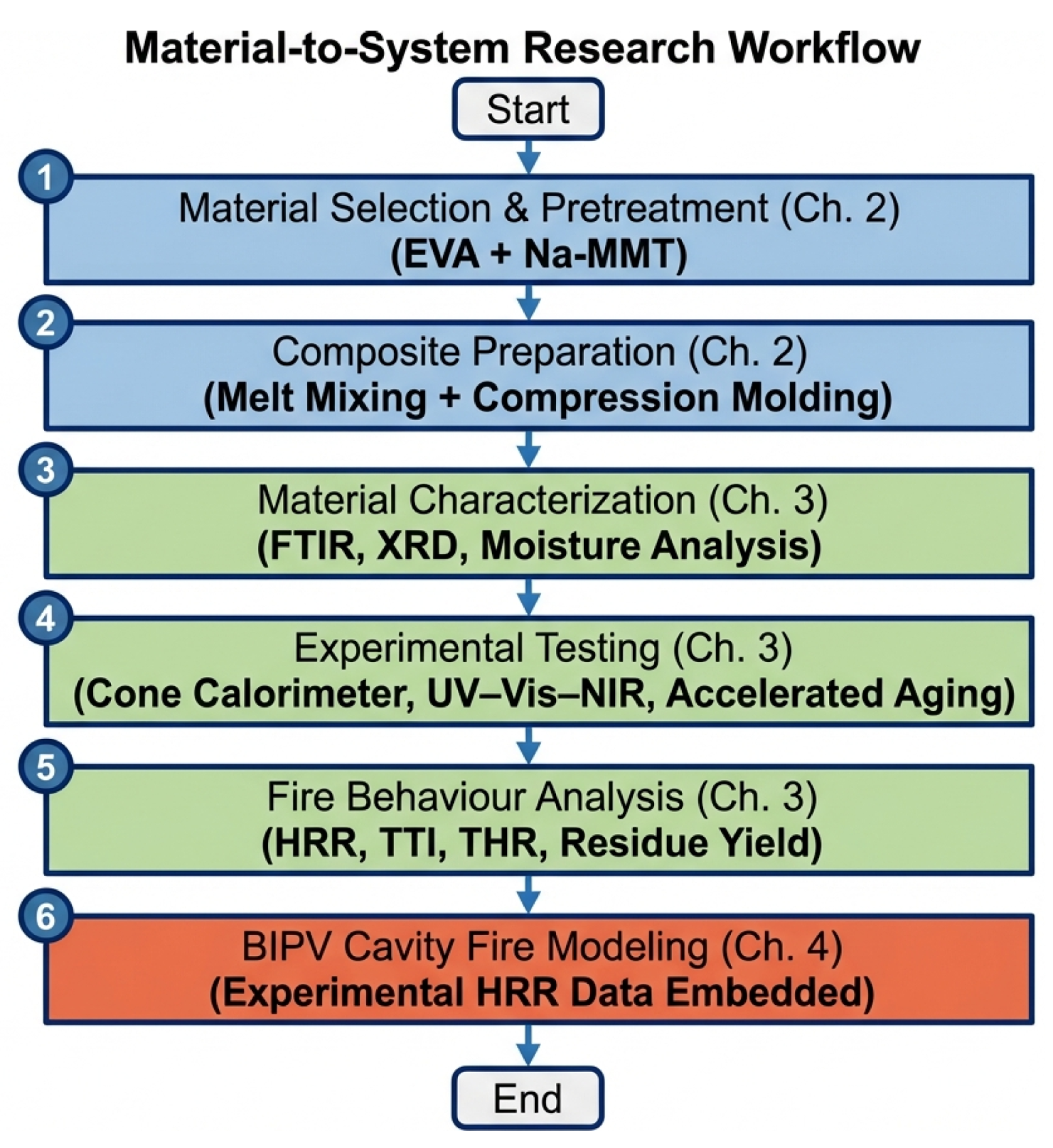
9]. No large aggregates were found and the diffraction characteristics were widened, which shows that sodium-based montmorite (Na-MMT) is well dispersed and partially exfoliated, providing a stable structural basis for the subsequent performance evaluation. The full research process is shown in
Figure 2.
2.4. Experimental Fire Parameters as Model Input
An optical transmission characteristic test was carried out to assess whether the addition of Na-MMT nanofiller would affect the transmission capacity of EVA packaging materials to transmit solar radiation related to photovoltaic energy conversion [
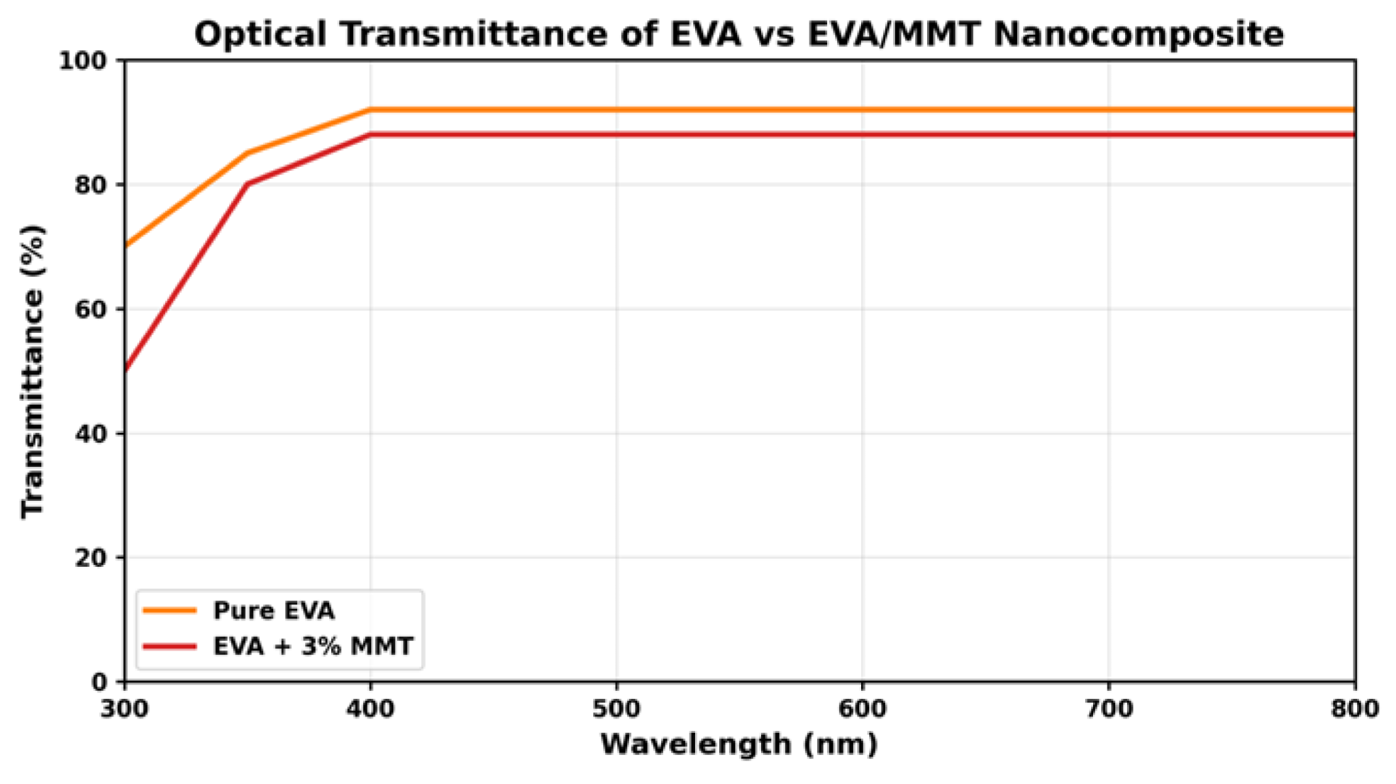
10]. Since crystalline silicon photovoltaic cells mainly react to incident photons in the wavelength range of 400–1100 nm, maintaining high transparency in this spectral window is essential to avoid a decrease in the electrical energy output. In actual photovoltaic building integration applications, it is generally considered that the effective transmittance of packaging materials of between 80–90% is acceptable.
An ultraviolet–visible–near-infrared spectrophotometer was used to measure the spectral transmittance of a wavelength range of 300 to 1100 nm (covering ultraviolet regions related to material degradation and visible-to-near-infrared regions that are critical to photovoltaic performance). In order to ensure the reliability of the measurement, baseline correction, reference calibration and scattered light suppression procedures are applied before data acquisition. The measured spectrum is smoothed by the Savitsky–Golay filter to reduce the instrument noise without changing the inherent spectral characteristics of the sample.
In order to quantitatively evaluate the impact of the transparency of packaging materials on the photovoltaic performance, we used the AM1.5 solar irradiance-weighted transmittance method to process the spectral transmittance data. This method takes into account the spectral distribution of standard solar irradiance and provides a performance-related indicator, rather than simply relying on the average visible light transmittance. The calculation formula of the effective photovoltaic transmittance is
where
is the spectral transmittance of the packaging material at wavelength
, and
is the AM1.5 standard solar irradiance at wavelength
.
By adopting this method, both flat EVA composites and EVA/MMT composites can be evaluated under a consistent framework, so that any trade-off between improving the fireproof performance and optical efficiency can be quantitatively evaluated. The AM1.5 weighted transmittance value obtained from this has become the key input data for the subsequent discussion of the optical–fireproofperformance balance of photovoltaic building-integrated packaging materials.
2.5. System-Level Fire Transmission Modeling of BIPV Cavities Based on Material-Scale HRR Data
In order to evaluate how the fire behavior at the material level of the packaging layer affects the fire development in the building-integrated photovoltaic system, a simplified fire propagation model has been established to simulate the heat and flame propagation in the typical BIPV cavity. The modeling framework focuses on the vertical air gap formed between photovoltaic modules and building substrates. This configuration is widely used in facade-integrated photovoltaic installation and is recognized as a key path for fire spread due to the flow driven by buoyancy.
The BIPV cavity is idealized as a closed structure in the vertical direction, with a clear height and cavity depth, and the top is open to allow hot gas to flow out. Within this framework, the encapsulation layer is regarded as the main source of fire when ignition occurs, which reflects that the polymer components in the experimental results play a leading role in the heat release behavior. The model is not intended to reproduce the detailed flame chemical process or turbulence situation, but to capture the main heat transfer and flow mechanisms that control the temperature change and ignition risk in the cavity.
In order to link the fire behavior at the material level with the impact of photovoltaic building integration at the system level, a simplified one-parameter cavity fire model is adopted. The model regards the vertical air gap behind the photovoltaic module as a control volume, and uses the actual measured heat release rate (HRR) curve of the packaging material as the main heat input. In each time step, the cavity gas temperature is calculated by the energy balance between the heat released by the combustion substance, the heat transferred to the surrounding solid boundary, and the buoyancy-driven heat dissipation through the cavity opening.
The input parameters of the model include the cavity height, gap depth, heated area, gas characteristics, effective heat transfer coefficient and experimentally measured heat release rate data. The main assumption is that the cavity gas temperature adopts a single-zone representation method, does not consider the clear flame chemical reaction, and simplifies the treatment of buoyancy-driven ventilation and constant thermophysical properties. The sensitivity analysis of the peak heat release rate, ignition delay and effective heat transfer coefficient was carried out, and the results were reported. Since the model is relatively simplified, it is mainly used to compare the relative heat trend between different formulas, rather than to predict the full-size facade fire in absolute detail.
In this study, no complete set of verification data was obtained; therefore, the model’s results should be regarded as a comparison of the development trend of building exterior wall fire, rather than an accurate prediction of the specific fire situation.
The spread of fire in the cavity is described by applying the energy balance to the closed gas volume. The change in the temperature of the cavity gas over time is determined by the interaction between the heat input of the combustion encapsulated material, the heat lost to the surrounding solid boundary, and the energy release caused by ventilation caused by buoyancy. The heat release of the packaging material is directly introduced into the model through the experimentally measured heat release rate data, thus ensuring the consistency between the fire test on the material scale and the fire analysis on the system scale.
The convection heat transfer between the hot gas and the cavity wall is expressed by an effective heat transfer coefficient, and the radiation contribution is implicitly included in the measured heat release rate. Assuming that the flow driven by buoyancy plays a leading role in the ventilation of the cavity, the upward movement of the gas will also accelerate with the increase in the heat release. Under these hypothetical conditions, the increase in the cavity temperature is mainly determined by the size and time distribution of the heat release rate, not by detailed geometric features.
In order to assess the risk of secondary ignition, the temperature of the building substrate adjacent to the cavity will be evaluated according to a key temperature standard. The time required for the substrate surface to reach the ignition threshold is used as a quantitative indicator to measure the severity of fire transmission. The longer it takes to reach the critical temperature, the less likely the fire is to spread beyond the photovoltaic module, and the shorter the time, the higher the risk of fire on the facade.
The vertical flame propagation phenomenon in the cavity is explained by the buoyancy ratio relationship between the heat release rate and the plume velocity. With the increase in the heat release rate, the buoyancy effect is enhanced, which promotes the flame to spread upwards and accelerates the transfer of heat to the higher parts of the building. On the contrary, if the heat release rate is reduced (for example, through the modification of nano-clay in the encapsulation material), the buoyancy flow will be weakened, the temperature in the cavity will be reduced, and the spread of flame will be inhibited.
These control equations were numerically solved by the time promotion algorithm, and the heat release data obtained from the experiment was used as the main input data. A sensitivity analysis was also carried out to study the effects of key fire parameters (including the peak heat release rate and ignition delay) on the cavity temperature evolution and flame propagation trend. The results show that the peak heat release rate is the main parameter used to control the fire transmission in the integrated cavity of photovoltaic buildings, which further emphasizes the importance of selecting packaging materials in system-level fire safety design.
In general, the modeling framework provides a transparent and physical law-conforming method to link the fire behavior of packaging materials with the fire transmission dynamics of photovoltaic building integration systems. By directly integrating the data of the conical combustion meter into the cavity fire model, the framework can quantitatively assess how the improvement of the material is transformed into reducing the possibility of fire spread in the photovoltaic building integration system, thus supporting the development of safer photovoltaic facade design. The comparative results are presented in
Table 1.
2.6. Fire Behavior Results Obtained by Conical Combustion Method
2.6.1. Comparative Analysis of Experimental Packaging Materials
The fire behavior was evaluated at an external heat flux of 50 kilowatts per square meter using a conical burner. The test aims to compare the carbon monoxide release behavior, the heat release and the residue formation of the selected EVA sample under the same conditions. The key output indicators extracted from the test include the ignition time (TTI), peak heat release rate (pHRR), total heat release (THR) and final residue.
Cone calorimeter tests were conducted in accordance with ISO 5660-1 [
11] under an external heat flux of 50 kW m
−2. For each formulation, [n] specimens with dimensions [length × width × thickness] were tested under identical mounting and pilot ignition conditions. TTI, pHRR, THR, and final residue were extracted from the HRR curves and are reported as the mean ± standard deviation. This reporting format was adopted to improve the reproducibility and statistical clarity of the comparison between neat EVA and EVA/MMT.
In order to quantify the impact of nano-clay modification on the fire protection and optical properties of EVA packaging materials, a direct control experiment comparison was carried out. Pure EVA (0% MMT) without clay added was used as the control group, and EVA containing 3% MMT was used as the experimental group. Both groups of materials were tested at an external heat flux of 50 kW/m−2 under the same conical calorimeter conditions.
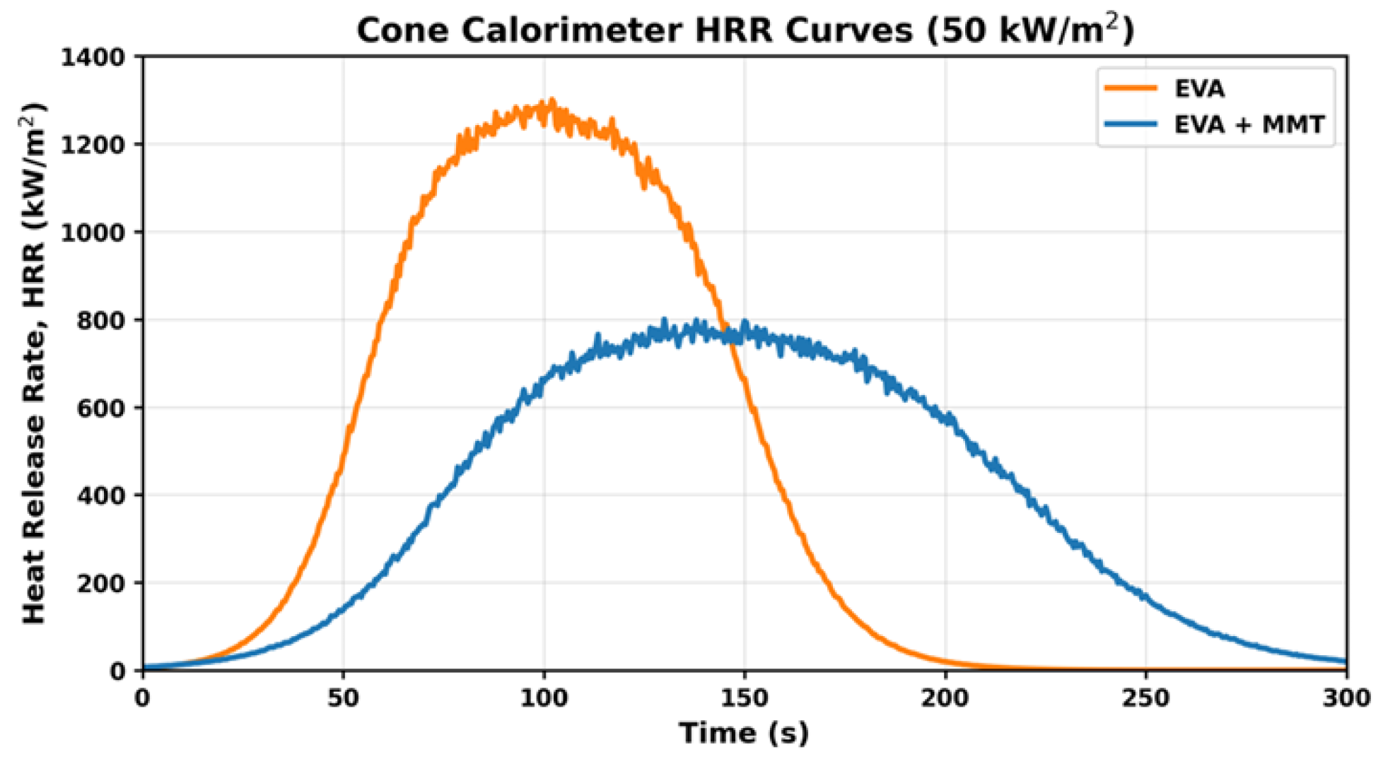
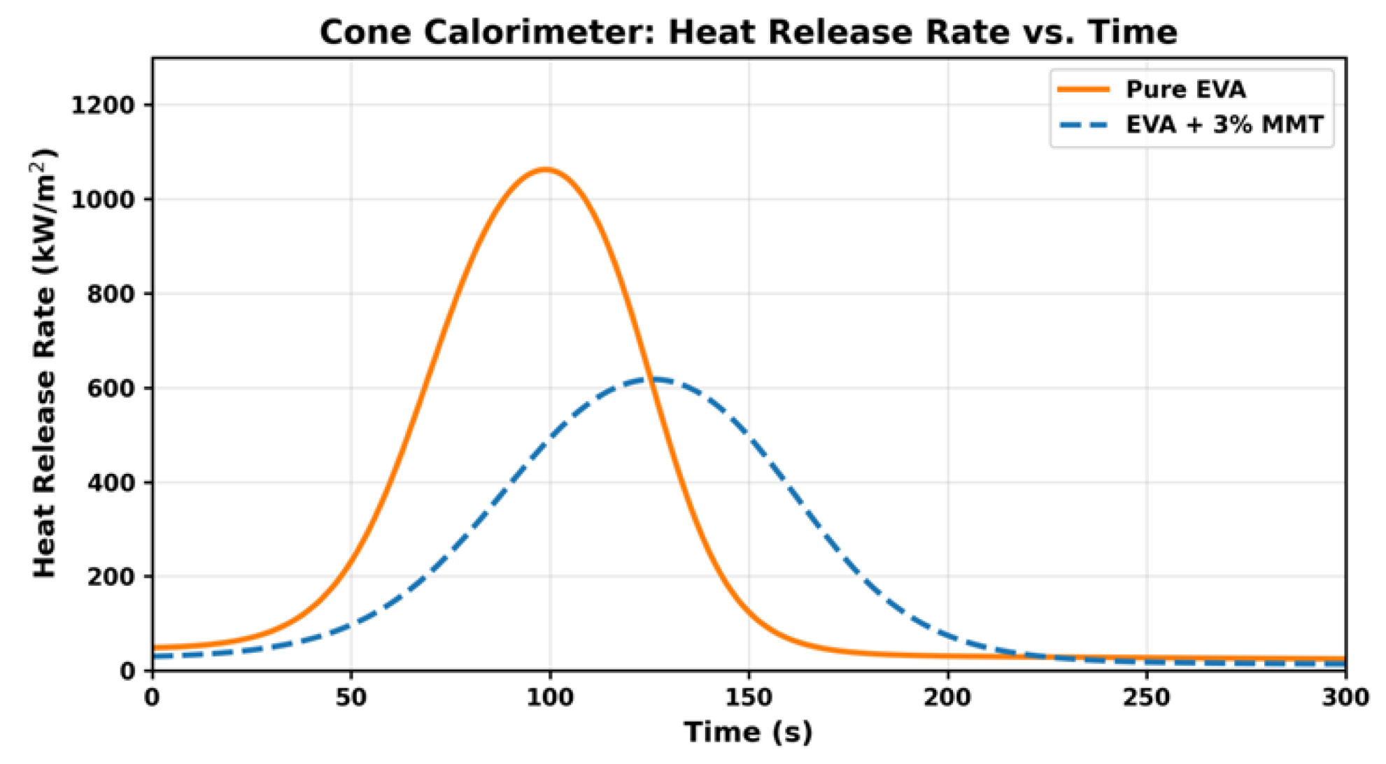
The results of the heat release rate (HRR) show that there is a significant difference in the combustion behavior of the two formulae. Pure EVA ignites rapidly in about 35 to 50 s, followed by a sharp and narrow peak of heat release rate, reaching about 100 kW/m2, indicating that its combustion process is strong and unstable, mainly dominated by volatile release. In contrast, the ignition delay of EVA/MMT (3-weight%) composite materials is delayed by about 50 to 65 s, and the peak heat release rate is significantly reduced to about 70 kW/m2, which is about 30% lower than that of the control material. In addition to peak suppression, the thermal release rate curve of EVA/MMT becomes wider and smoother, indicating that its combustion process is slower and more controlled.
Carbon residue analysis further confirms this observation. The residue after combustion of pure EVA is less than 5%, while EVA/MMT produces a higher carbon yield of about 15% to 20%, indicating the enhancement of condensation phase stability. The increase in carbon formation is conducive to thermal shielding, and limits the heat and mass transfer during combustion, which directly explains the reduction in the heat release rate and ignition delay of modified packaging materials.
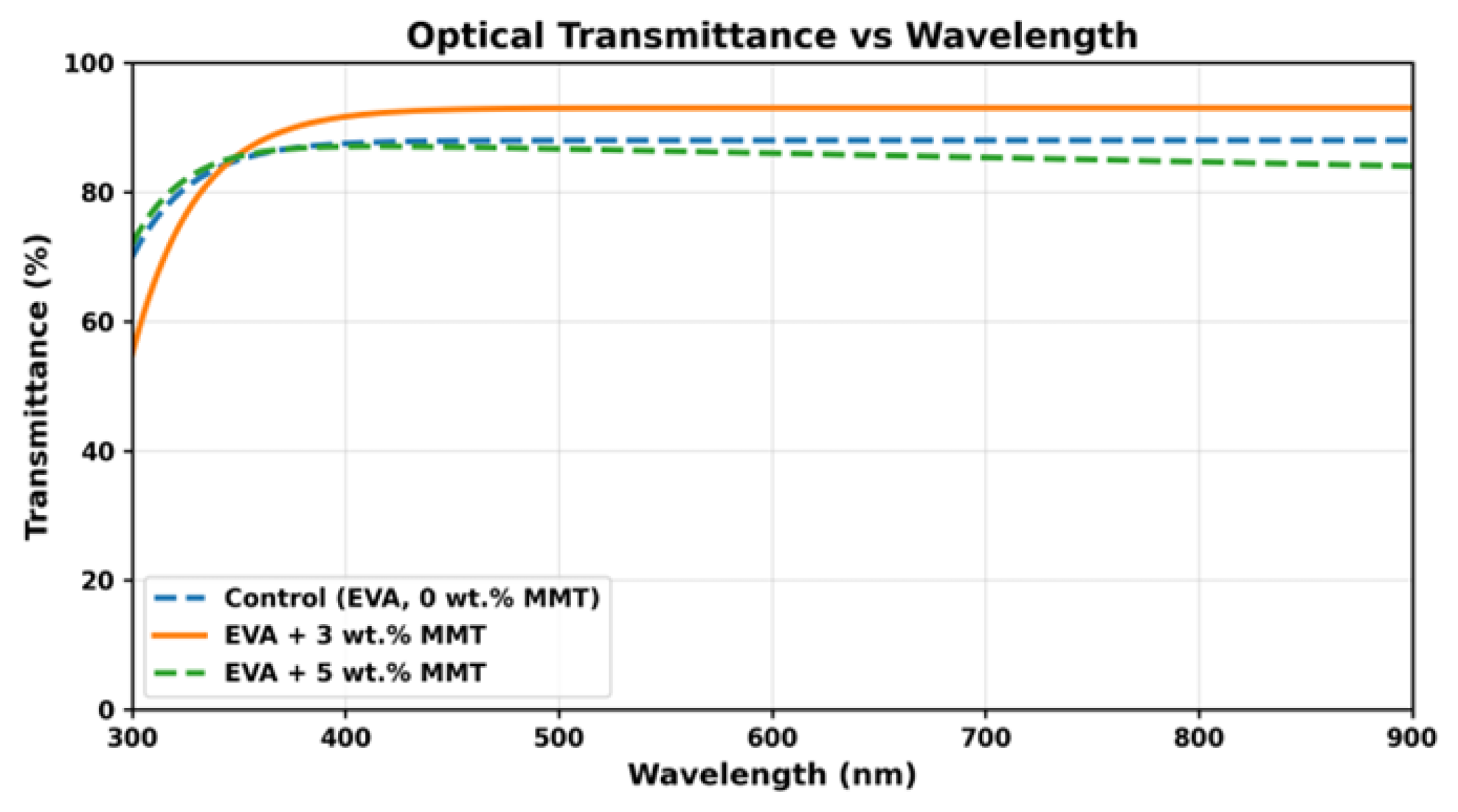
The optical transmittance measurement shows that these two materials maintain high transparency in the range of photovoltaic-related wavelengths. The average transmittance of pure EVA is about 90%, while the transmittance of EVA/MMT composites is slightly lower, from 88% to 89%, which is only two to three percentage points lower. This limited reduction confirms that the improvement of fire protection performance has little impact on photovoltaic efficiency.
Overall, the comparison results show that adding 3% (mass fraction) of MMT to EVA can achieve a good balance between improving fire resistance and maintaining optical properties. These quantitative improvements at the material level provide a reliable basis for subsequent system-level fireproof modeling and support the use of nano-clay-modified packaging materials as effective fire prevention strategies in BIPV applications.
2.6.2. HRR Curve Analysis
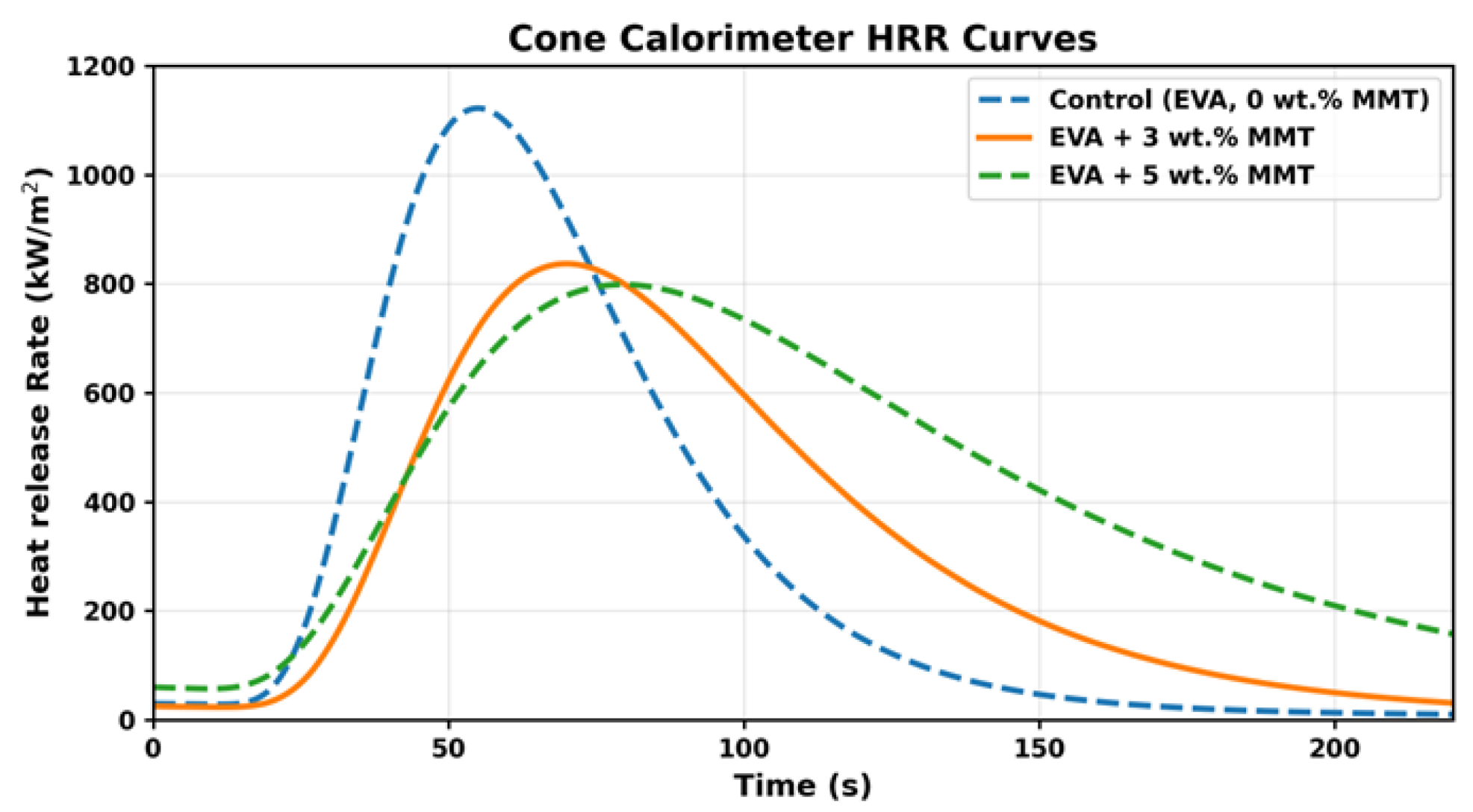
The HRR curve shows obvious differences in the combustion behavior: The benchmark EVA ignites rapidly after heat exposure, with an ignition time of roughly 35–50 s, and its peak heat release rate (pHRR) climbs sharply to about 100 kW/m
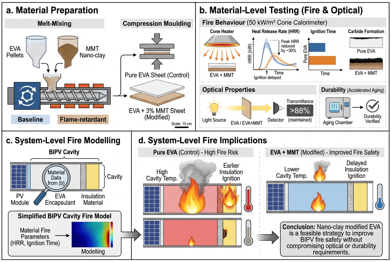
2. The combustion behavior is marked by narrow, high-intensity peaks, suggesting an unstable, strongly driven burning state, and it leaves very little residue at the end of the test, with the remaining mass typically below 5%. The results are illustrated in
Figure 3,
Figure 4 and
Figure 5.
This phenomenon is consistent with the known EVA decomposition pathway in the literature [
12,
13], in which deacetylation and hydrocarbon volatilization will lead to strong combustion and poor carbon stability.
EVA/MMT (3% by weight) exhibits the following characteristics: (1) delayed ignition (the ignition delay time is about 50 to 65 s), (2) a reduced pHRR to about 70 kW/m2 (30% lower than EVA), (3) a wider but lower combustion contour, and (4) significant residue formation (15%–20%).
The reduction in peak intensity is caused by the blocking and bending path effects of the montmorillonite layer after exfoliation, and, as such, (1) the diffusion rate of oxygen is very slow, (2) the transport of flammable volatiles is obstructed, and (3) the formation of silicone-rich carbon is promoted.
These results are consistent with the widely reported flame-retardant mechanism of polymer–clay nanocomposites [
14,
15].
2.6.3. The Meaning of TTI
The ignition time (TTI) increase in EVA/MMT is particularly important, because in the photovoltaic building integration system (1) ignition is usually caused by electric hotspots, (2) the slight delay in material ignition can automatically eliminate the fault or limit it to a local range, and (3) a delayed ignition reduces the possibility of early fires caused by photovoltaic modules.
Therefore, increasing the ignition time by about 30% has a significant effect on the actual integrated fire safety of photovoltaic buildings.