1. Introduction
In the context of transportation modernization strategy, smart highways have emerged as an important development direction for new transportation infrastructure [
1,
2,
3,
4]. Real-time structural health monitoring of asphalt pavement is critical for ensuring pavement service life. Internal cracks within asphalt pavement layers represent a critical form of structural distress. They typically initiate from the bottom or middle of pavement layers and propagate upward under repeated traffic loading and environmental effects. Unlike surface cracks that can be detected through visual inspection, internal cracks remain hidden until they reach the pavement surface. Early detection of internal crack initiation and propagation through embedded sensing technology is necessary for preventing extensive deterioration [
5]. Therefore, timely identification of such damage is essential for determining road-maintenance indicators.
Fiber optic sensing technologies have been demonstrated to be suitable for complex environments, offering strong durability, electromagnetic interference resistance, and low maintenance costs [
6,
7,
8]. Among these technologies, distributed acoustic sensing enables real-time continuous measurement; however, its signal-to-noise ratio is relatively low [
9,
10]. Fiber Bragg grating (FBG) technology offers high accuracy but has a limited monitoring range [
11,
12]. Asphalt mixtures are typical viscoelastic composites with pronounced time- and temperature-dependent behavior [
13]. The linear viscoelastic properties and dynamic modulus of asphalt mastics, which are strongly influenced by filler characteristics, play a key role in controlling the mechanical response and deformation behavior of asphalt mixtures [
14,
15]. These complexities underscore the need for reliable internal strain monitoring techniques to capture localized deformation and interfacial mechanical behavior.
Compared with distributed acoustic sensing and FBG technology, ultra-weak fiber Bragg grating (UWFBG) technology employs gratings with an ultra-low reflectivity below 0.1%. This enables time-division multiplexing of thousands of sensing points along a single optical fiber without wavelength collision. The ultra-low reflectivity reduces multiple reflection interference, ensuring good signal quality. These advantages of high spatial resolution, wide coverage, and low per-point cost make UWFBGs suitable for internal strain monitoring in smart highway networks [
16,
17,
18]. Therefore, UWFBG technology represents a promising solution for the comprehensive structural health monitoring of asphalt pavements.
However, studies on the mechanical behavior of UWFBG sensors embedded in pavement structures under in-service conditions remain relatively limited. Current research [
14,
15,
16] is mainly focused on applications of this sensor, such as in vehicle detection and vibration sensing, while insufficient attention has been paid to the deformation coordination and interfacial mechanical behavior between this sensor and the asphalt mixture. Therefore, it is particularly necessary to conduct a deeper investigation into the mechanical response mechanism of UWFBG sensors embedded in pavement structures. Given the limited research on the mechanical behavior of UWFBG sensors, this study draws upon investigations of embedded FBG sensors for methodological and theoretical support.
The influences of the vertical placement of FBG sensors on strain measurement performance have been examined in the literature [
19,
20,
21,
22]. For example, Li et al. [
19] investigated the cooperative deformation behavior between the FBG sensor and asphalt mixture and pointed out that when a sensor is placed at structural locations with large strain gradients in a vertical direction, deformation incompatibility is prone to occur between the sensor and the asphalt mixture, thereby leading to significant discrepancies between the measured strain by this sensor and the strain of the host material. Hu et al. [
20] analyzed the strain response characteristics of an FBG sensor embedded within asphalt pavements under different vertical placement positions and found that variations in vertical placement significantly affect the strain response amplitude and signal stability. Liu et al. [
21] further reported that an improper vertical placement alters the interfacial stress distribution between the FBG sensor and asphalt mixture, thereby weakening the efficiency of effective strain information transfer. Braunfelds et al. [
22] conducted a strain monitoring of in-service asphalt pavement structures using an embedded FBG sensor and found that FBG sensors embedded at different vertical depths exhibit significant differences in recorded strain responses; some of the differences could not be adequately explained by conventional continuum assumptions. The above studies reveal, from different perspectives, that abnormal strain responses induced by variations in vertical embedding positions essentially originate from changes in the cooperative deformation capability and the complexity of interfacial mechanical behavior at the sensor–asphalt mixture interface. Therefore, investigation into the interaction mechanisms at the sensor–asphalt mixture interface is necessary to clarify the influence of interfacial properties on strain measurement accuracy.
To explain the phenomenon of the strain response deviation and instability induced by the vertical placement of the sensor, related research [
23,
24,
25] has increasingly focused on the mechanical behavior at the sensor–asphalt mixture interface. Han et al. [
23] pointed out that the modulus mismatch between the embedded strain sensor and the asphalt mixture induces stress concentration in the sensor–asphalt mixture interfacial region, and that this effect varies significantly with vertical placement position, thereby affecting strain transfer accuracy. Furthermore, another study [
24] by them showed that when local damage or debonding occurs at the interface, the stability and reliability of strain monitoring signals are significantly reduced. Meanwhile, they also found that the interfacial region is often the location where structural damage initiates preferentially, and the degradation of its mechanical properties plays an important role in governing the overall structural response [
25]. To sum up, the vertical placement position of the sensor controls the stability and accuracy of strain transfer by altering the stress state at the sensor–asphalt mixture interface, which is also one of the reasons why the study focuses on deformation compatibility at the interface.
The mechanical issues at the embedded-sensor–asphalt mixture interface focus on elucidating the formation mechanisms of stress distribution, load transfer, and damage evolution within the interfacial region under the heterogeneous structural characteristics of the asphalt mixture. To investigate the influence of material heterogeneity on the interfacial mechanical behavior between the sensor and asphalt mixture, the mechanical interaction between embedded components and asphalt mixture has been analyzed by means of mesoscale finite element methods. Mo et al. [
26] and Du et al. [
27] demonstrated that explicitly describing the internal compositional differences of materials at the mesoscale enables a more accurate representation of local stress distribution characteristics and interfacial stress states. The results reported by Kim et al. [
28] and Chen et al. [
29] indicate that the interfacial region is often the preferential location for damage initiation, and the degradation of its mechanical properties has a significant influence on the overall structural response; therefore, an explicit characterization of interfacial mechanical behavior is critical for revealing the initiation and propagation of damage. Collectively, simultaneously characterizing the mechanical responses of the sensor, the sensor–asphalt mixture interface, and the surrounding asphalt mixture at the mesoscale provides an effective approach for analyzing the effects of sensor placement variations on the strain response characteristics and interfacial behavior.
At present, increasing attention has been paid to the relationship between strain response and interfacial stability. Numerical analyses conducted by Liu et al. [
30] showed that embedded sensors located at layers with concentrated vertical strain are usually associated with a faster damage evolution process. Through cooperative deformation tests of embedded FBG sensors, Liao et al. [
31] found that when sensors are vertically placed in high-strain regions, the strain response amplitude is enhanced, whereas the deformation compatibility between the sensor and asphalt mixture is significantly reduced. From a theoretical perspective, Dong et al. [
32] pointed out that interfacial stress is more likely to concentrate in structural layers with large vertical strain gradients, thereby reducing the efficiency of strain transfer. Overall, the existing studies indicate that the vertical placement of a sensor is intrinsically linked to strain response enhancement, interfacial stability degradation, and the deterioration of cooperative deformation capability; however, systematic investigations into these issues remain insufficient. The aforementioned studies have systematically examined strain distribution, interfacial damage, and the sensor placement of embedded FBG sensors in asphalt mixtures, which are essentially governed by the interaction mechanisms between the sensor and the asphalt mixture. Considering the similarities in structural characteristics and sensing principles between UWFBG and conventional FBG sensors, these research approaches can be applied to investigate UWFBG sensor mechanical performance under vertical placement conditions.
To address these issues, this study aims to analyze the influence of a built-in UWFBG sensor on the interfacial properties between the sensor–asphalt mixture. Mesoscale finite element beam models of an asphalt mixture with an embedded UWFBG sensor were established. The relationships among UWFBG strain response sensitivity, interfacial damage, and deformation coordination were investigated. A deformation coordination index was established based on strain response, interfacial stiffness degradation, and contact opening, and recommendations were made for the vertical placement position of the UWFBG sensor.
2. Materials and Methods
2.1. Material
Based on the mesoscale finite element approach described above, an AC-13 asphalt mixture was selected as the research subject to investigate the effects of the embedding depth of an embedded UWFBG. The gradation of the AC-13 mixture is shown in
Table 1. The asphalt mixture has an asphalt–aggregate ratio of 4.77%. In the model, aggregates larger than 2.36 mm were considered coarse aggregates, while aggregates with a size of 2.36 mm or smaller were classified as fine aggregates. Fine aggregates were mixed with asphalt binder to produce the asphalt mortar. Styrene-Butadiene-Styrene (SBS) (I-D)-modified asphalt, supplied by Shandong Huate Road Materials Co., Ltd. (Shandong, China), was used in this study. Its properties are shown in
Table 2. The coarse aggregates were basalt obtained from Baoding Qingyuan Jiangyue Basalt Aggregate Plant (Baoding, China) and their technical indicators are shown in
Table 3, while the fine aggregates were limestone supplied by Tangshan Qingfeng Aggregate Plant (Tangshan, China) and their indicators are shown in
Table 4. The mineral filler was provided by Baoding Laishui Tongshun Building Materials Co., Ltd. (Baoding, China); its indicators are shown in
Table 5.
2.2. Meso-Finite Element Modeling of Asphalt Mixture Beams Containing UWFBG with Different Embedding Positions
To investigate the influence of the vertical embedding position of UWFBG sensors on their strain response characteristics and deformation coordination with asphalt mixtures, this study conducted a three-point bending simulation to analyze the mechanical behavior of the UWFBG sensor–asphalt mixture system. The three-point bending configuration can effectively reproduce the flexural mechanical response of beam specimens and is consistent with the stress-state description of asphalt mixture beams specified in JTG 3410-2025 [
33]. The support span of the model was set to 200 mm. Displacement-controlled loading was applied at the midspan with a loading rate of 50 mm/min to simulate a quasi-static loading process.
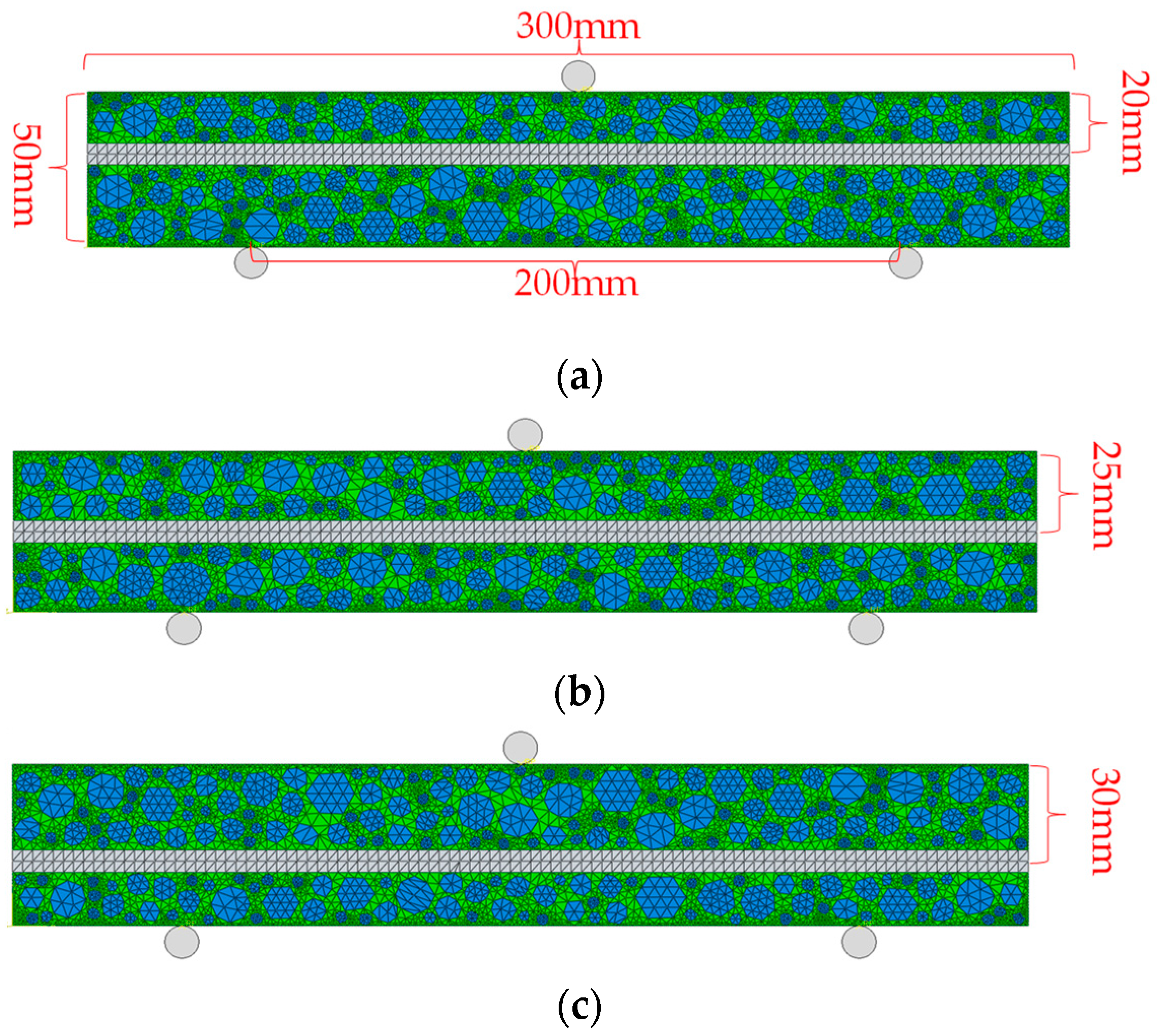
Although asphalt mixtures are inherently three-dimensional heterogeneous materials, a two-dimensional modeling approach was adopted in this study to focus on the cross-sectional mechanical interaction between the embedded UWFBG sensor and the surrounding asphalt mixture. The numerical model was implemented under a plane strain assumption, which is commonly used for beam bending analysis where the specimen width is much larger than the characteristic aggregate size. Under three-point bending loading, the dominant stress transfer and strain redistribution mechanisms occur primarily within the beam cross-section. Previous mesoscale studies have also adopted two-dimensional models to capture the essential stress redistribution characteristics while reducing computational cost. Considering that the primary mechanical response of the beam under three-point bending can be effectively characterized by the stress–strain transfer behavior within the cross-section, a two-dimensional finite element modeling approach was adopted. This two-dimensional model is capable of capturing the vertical stress–strain transfer characteristics while significantly reducing the degrees of freedom and computational cost, which is beneficial for detailed analysis of interfacial mechanical behavior and sensor strain response. In the two-dimensional model, the asphalt mixture beam was defined as a plane structure with a length of 350 mm and a thickness of 50 mm. The UWFBG sensor was represented using an equivalent modeling method and simplified as a rectangular cross-section with a width of 8 mm. The sensor was arranged along the vertical direction of the beam to reflect its mechanical behavior and deformation characteristics in the embedded state.
Based on the stress distribution characteristics within the beam cross-section under three-point bending, three representative vertical embedding positions were defined in the model. The position near the upper edge of the beam was defined as top embedding (T), where compressive stress dominates. The position near the neutral axis was defined as middle embedding (M), corresponding to the transition zone from compressive to tensile stress. The position near the lower edge of the beam was defined as bottom embedding (B), which is located in the maximum tensile stress region and exhibits a relatively high strain level.
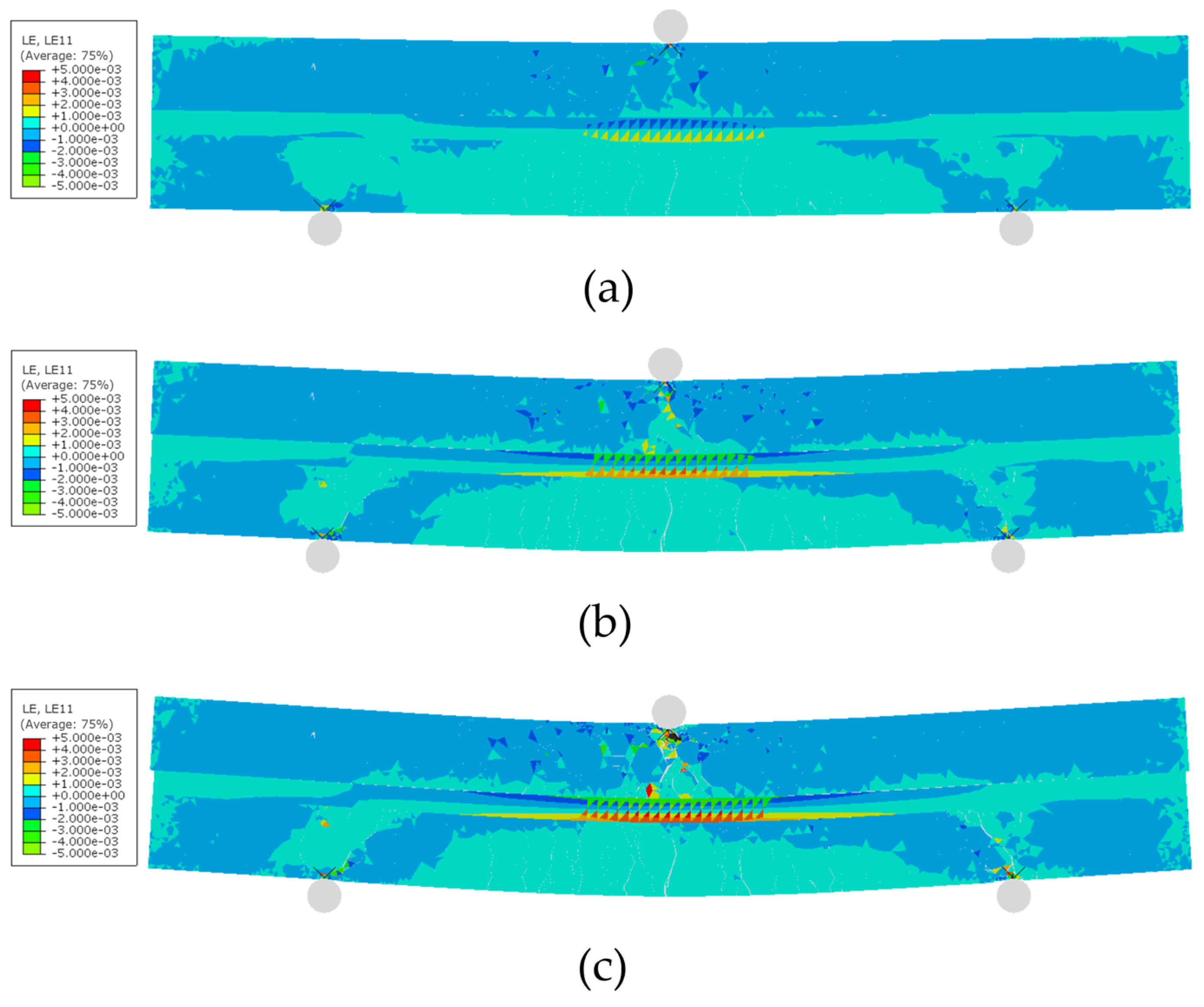
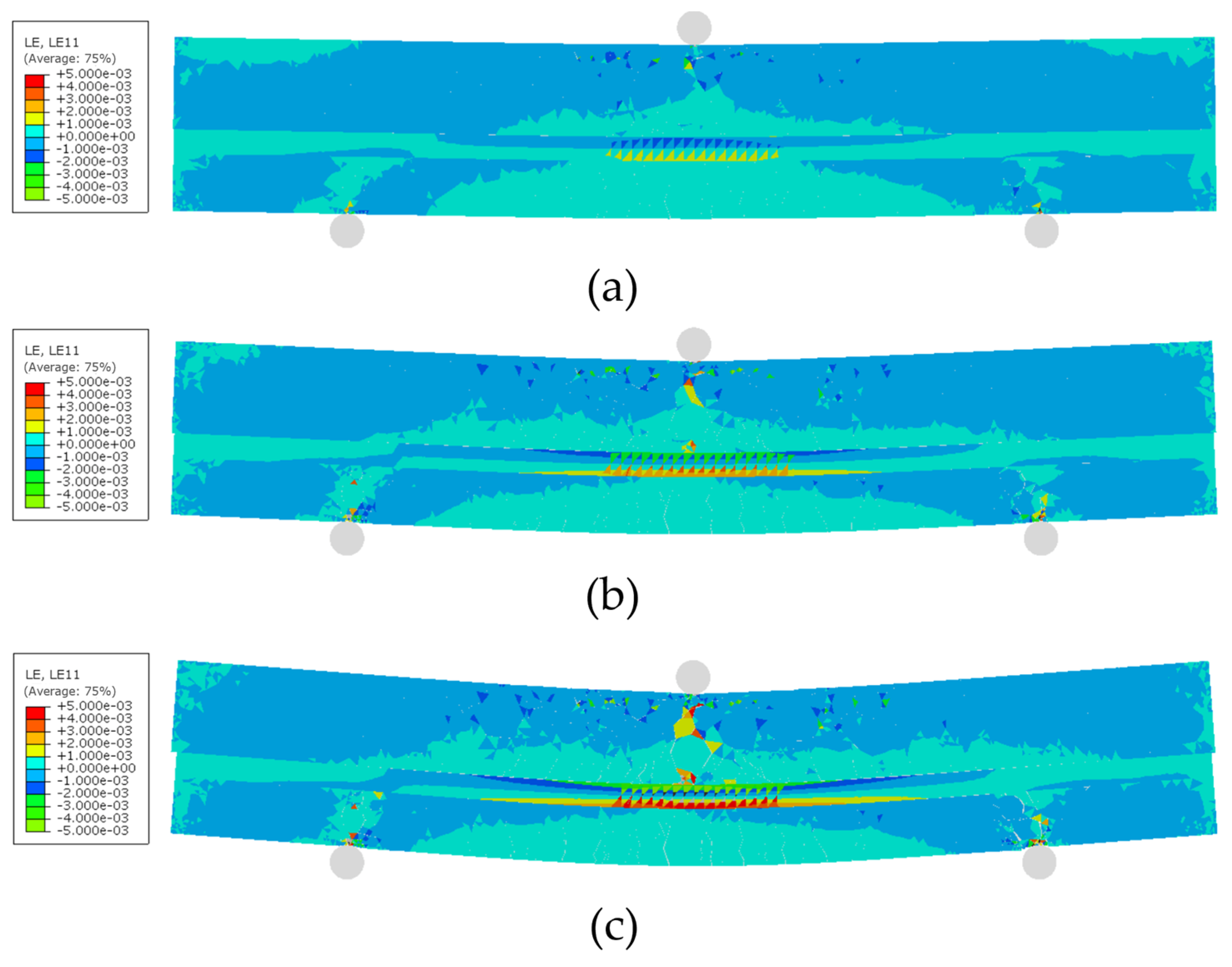
Based on the above embedding scheme, three two-dimensional finite element models of asphalt mixture beams with different vertical embedding positions were established. During mesh generation, local mesh refinement was applied to the UWFBG sensor and its surrounding regions to improve the accuracy of interfacial stress distribution and damage evolution calculations. Coarser meshes were adopted in regions away from the sensor to balance computational accuracy and efficiency. The three models differ only in the vertical embedding position of the UWFBG sensor, while all other geometric parameters, interfacial conditions, and loading conditions remain identical to ensure the comparability of numerical results under different embedding positions. The models are shown in
Figure 1. It can be observed that the support span was set to 200 mm, and displacement-controlled loading was applied at the midspan. The two supports were modeled as roller supports. Contact interaction between the beam and the supports was defined using a surface-to-surface contact formulation with a friction coefficient to simulate the interaction between the specimen and the loading fixtures. In addition, geometric nonlinearity was activated in the numerical analysis to account for potential nonlinear deformation effects during the loading process.
The interface between the UWFBG sensor and the asphalt mixture was described using a cohesive zone model. This model characterizes the interfacial mechanical response under external loading by defining normal and tangential traction–separation relationships. It can simulate the entire interfacial process from initial bonding to damage initiation and progressive damage evolution, which may ultimately lead to interfacial cracking or debonding. By introducing parameters such as interfacial stiffness degradation, the influence of interfacial damage development on the strain transfer capability and deformation coordination between the sensor and asphalt mixture can be captured.
The material and interface parameters used in the meso-finite element model are presented in
Table 6 and
Table 7, including elastic moduli and Poisson’s ratios for bulk materials, as well as fracture energy and cohesive strength for interfaces. In this study, the asphalt mortar phase was modeled using a simplified linear elastic constitutive model. Although asphalt materials exhibit viscoelastic behavior, the loading duration considered in the present three-point bending simulation is relatively short. Therefore, the deformation response is mainly governed by instantaneous mechanical behavior and interfacial damage evolution. The simplified elastic assumption allows the strain transfer mechanism between the UWFBG sensor and the surrounding asphalt mixture to be more clearly analyzed. The cohesive zone model was adopted to simulate the interfacial mechanical behavior between different material phases in the mesoscale model. Previous studies [
28,
29,
30] have reported cohesive parameters for different material interfaces within asphalt mixtures. Based on these reported values, the parameters used in the present model were selected from the literature and slightly adjusted to better represent the mechanical interaction between different phases in the mesoscale simulation. Based on the above modeling strategy, the strain response characteristics of UWFBG sensors and the interfacial mechanical behavior under different vertical embedding positions can be obtained, providing a reliable numerical basis for the subsequent analysis of deformation coordination mechanisms.
2.3. Laboratory Test
The laboratory three-point bending test was conducted on asphalt mixture beam specimens to verify the reliability of the B model. The experimental setup was designed to reproduce the boundary conditions and loading configuration used in the numerical simulation. The asphalt mixture beams were prepared using the same AC-13 gradation described in
Section 2.1. According to JTG 3410-2025 [
33], the specimen preparation was conducted, which is illustrated in
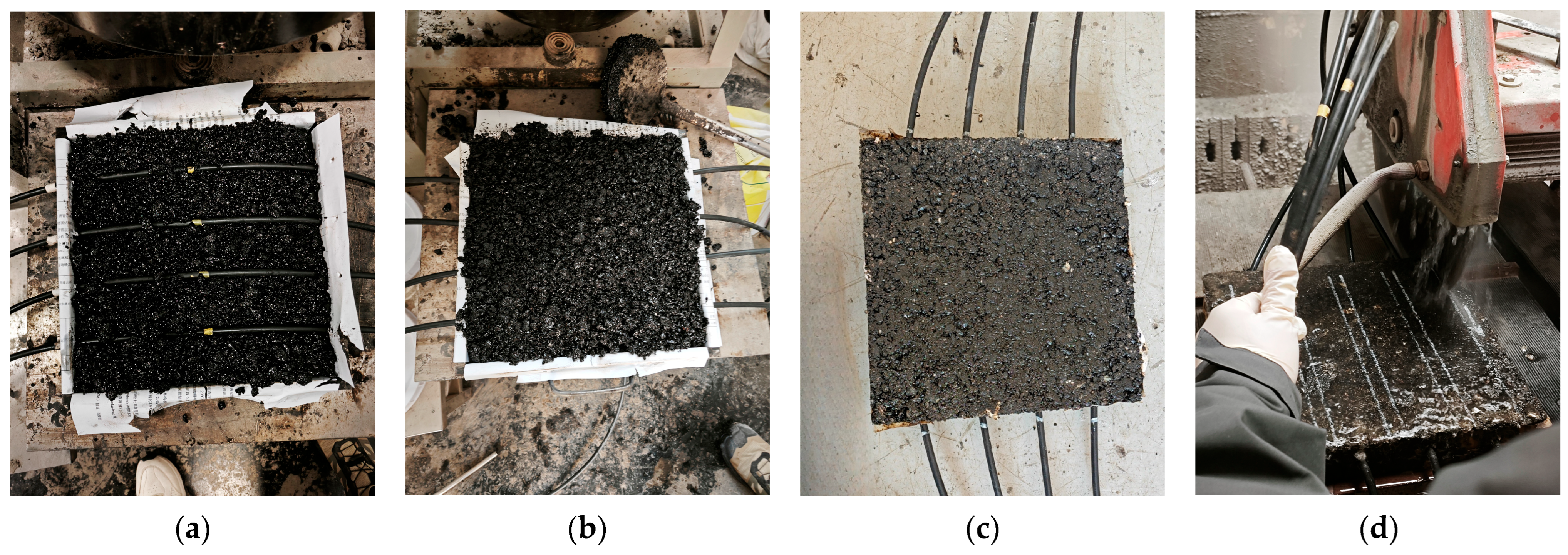
Figure 2. To accommodate the embedding of the UWFBG sensor, a specialized rut plate mold (300 mm × 300 mm × 50 mm) with a 10 mm side opening was first fabricated. The distance from the center of the hole to the top surface of the specimen was 20 mm. Initially, 60% of the total asphalt mixture weight was uniformly placed into the mold. The UWFBG sensor was then embedded in the center of the mixture, with the fiber grating positioned 20 mm below the top surface of the specimen. Subsequently, the remaining asphalt mixture was added to fill the mold from the edges toward the center. The roller of the compactor was preheated to approximately 100 °C. The mold containing the mixture was placed on the platform of the roller for compaction. Afterwards, the mold with the compacted specimen was cooled at room temperature for at least 12 h before demolding. Finally, the specimen was cut to dimensions of 300 mm × 50 mm × 50 mm using a cutting machine.
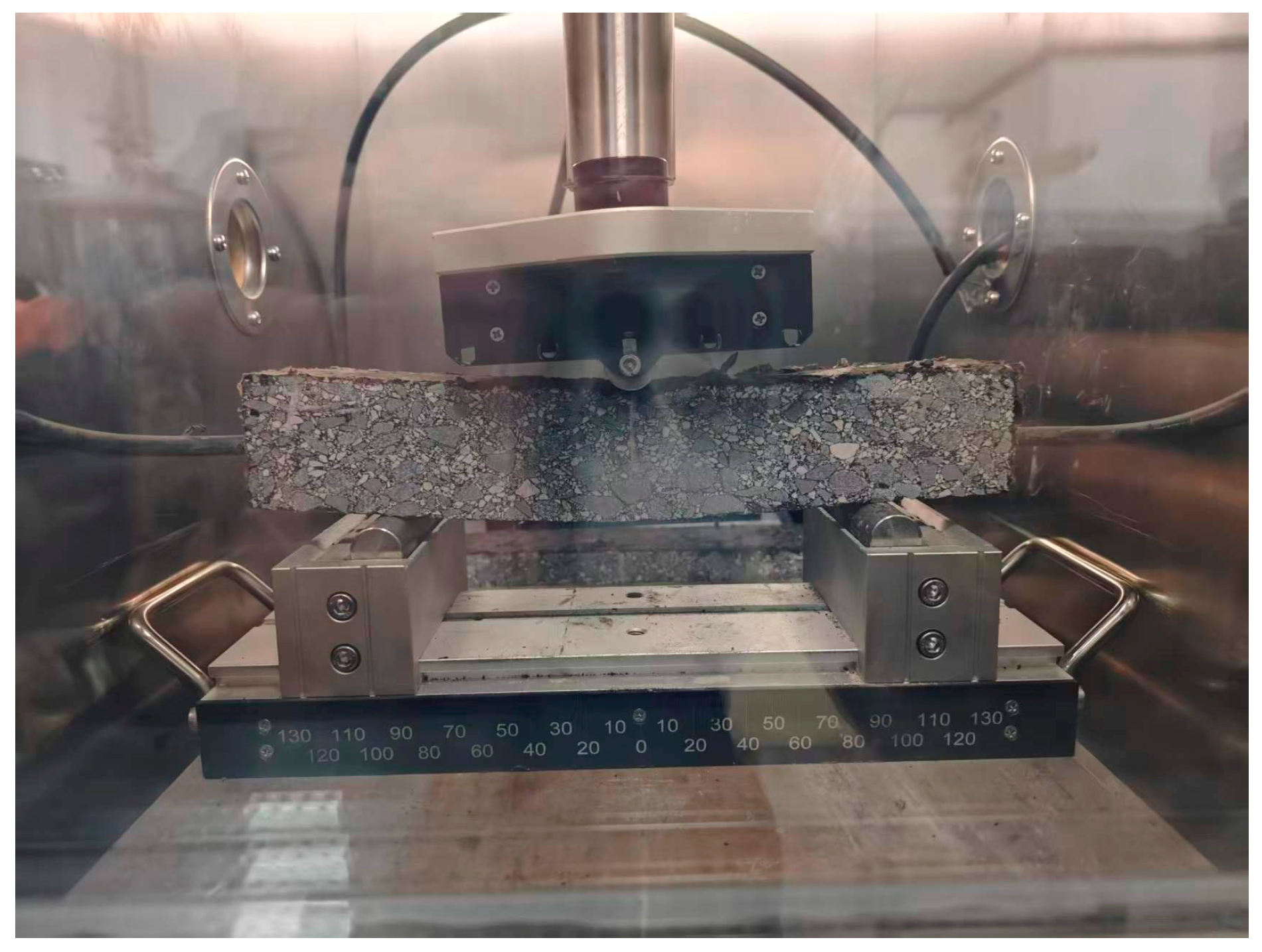
To ensure consistency between the simulation and experimental loading conditions, a three-point bending test was conducted using a Universal Testing Machine (UTM, Shanghai Nuolai Technology Development Co., Ltd., Shanghai, China). The support span of the beam specimen was set to 200 mm, and displacement-controlled loading was applied at the midspan with a loading rate of 50 mm/min. During the experiment, the applied load and the corresponding midspan displacement were continuously recorded to obtain the experimental load–displacement relationship of the asphalt mixture beam. The experimental procedure is illustrated in
Figure 3. The experimental results provide a reference for assessing the rationality of the numerical model and indicate that the proposed mesoscale model can reasonably capture the overall deformation trend of the asphalt mixture beam under three-point bending loading.
2.4. Development of Monitoring Performance Index
To investigate the relationships among the strain response sensitivity, interfacial stability, and deformation coordination of UWFBG sensors, this study proposed three key rating indicators, namely the lateral tensile strain change rate of the UWFBG core, the interfacial damage degree, and the interfacial opening displacement. Based on these indicators, a deformation coordination index was established to provide a theoretical basis for optimizing the embedding depth of UWFBG sensors in asphalt pavement monitoring.
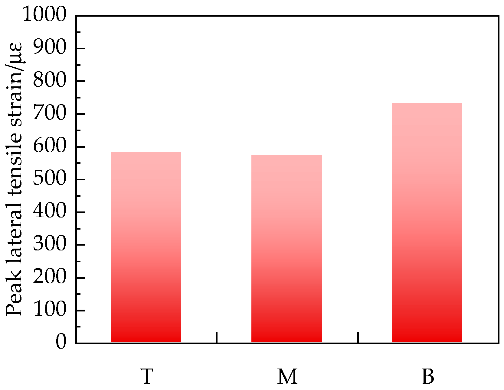
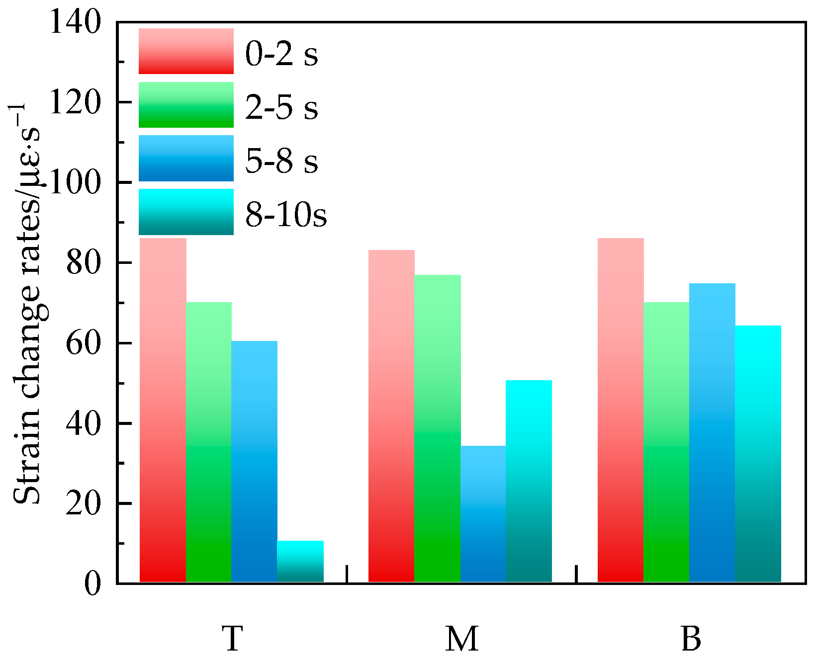
To characterize the deformation response of the asphalt mixture beams during loading and further reflect the monitoring accuracy of UWFBG sensors, the lateral tensile strain change rate of the UWFBG core was adopted as the monitoring accuracy indicator. The strain change rate can directly represent the dynamic response capability of the sensor output during the loading process. Compared with lateral tensile strain, it more effectively reflects monitoring sensitivity and response reliability. The calculation method is given in Equation (1).
where
is the lateral tensile strain of the UWFBG core at the
i-th time step (με);
is the loading time at the
i-th time step (s);
is the lateral tensile strain change rate of the UWFBG core (με/s).
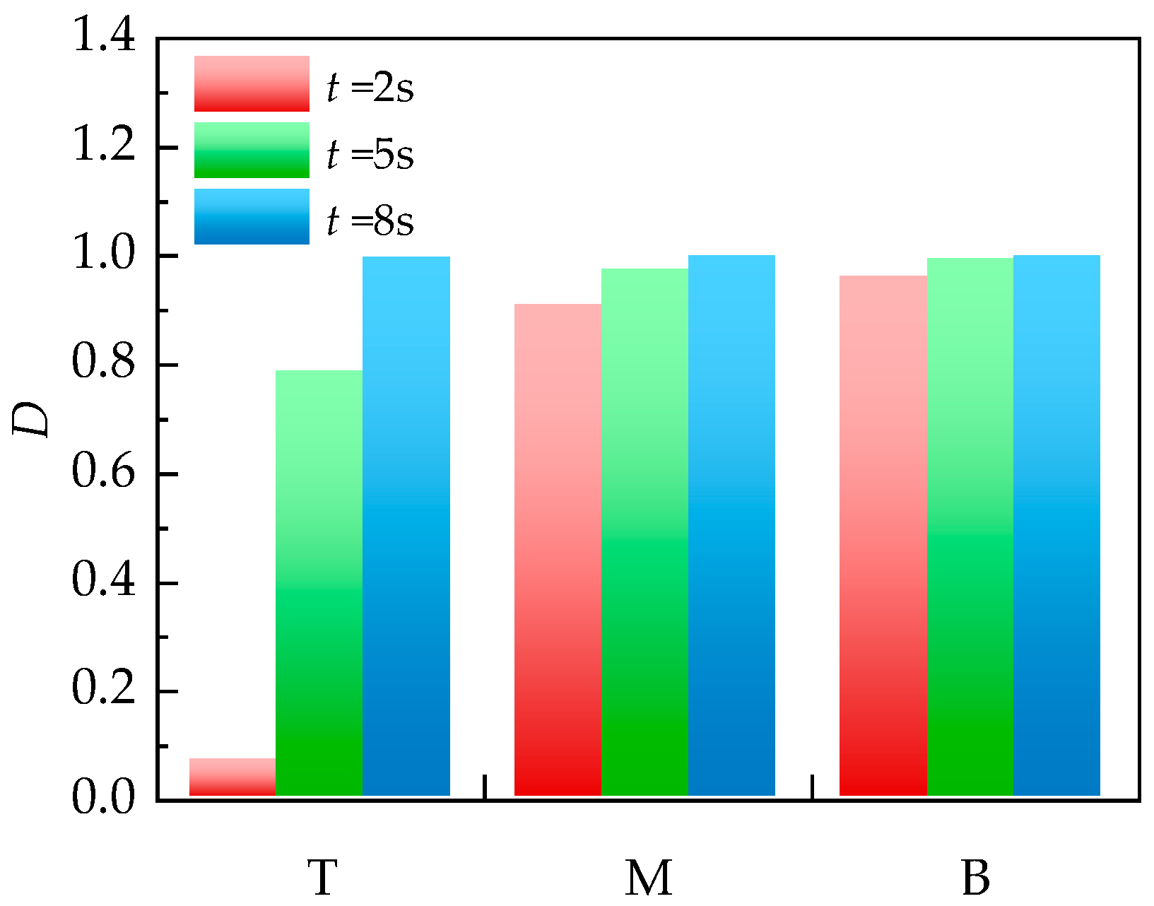
To describe the evolution of interfacial damage, the interfacial damage degree (
D) was employed as an evaluation indicator.
D was calculated based on the cohesive zone model and ranges from 0 to 1, representing the damage evolution from complete bonding to complete failure. When
D = 0, the interface remains fully bonded. As
D approaches 1, the interface enters a severe damage stage and tends to fail or has already completely failed. The calculation method is shown in Equation (2).
where
seff is the effective displacement at damage initiation of the computing unit (mm);
smax is the maximum effective displacement of the computing unit in loading history (mm);
sf is the effective displacement of the computing unit at complete failure (mm).
To characterize the interfacial separation or compression state in the normal direction, the interfacial opening displacement (
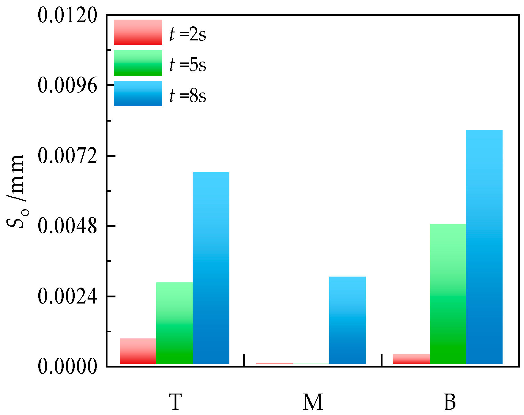
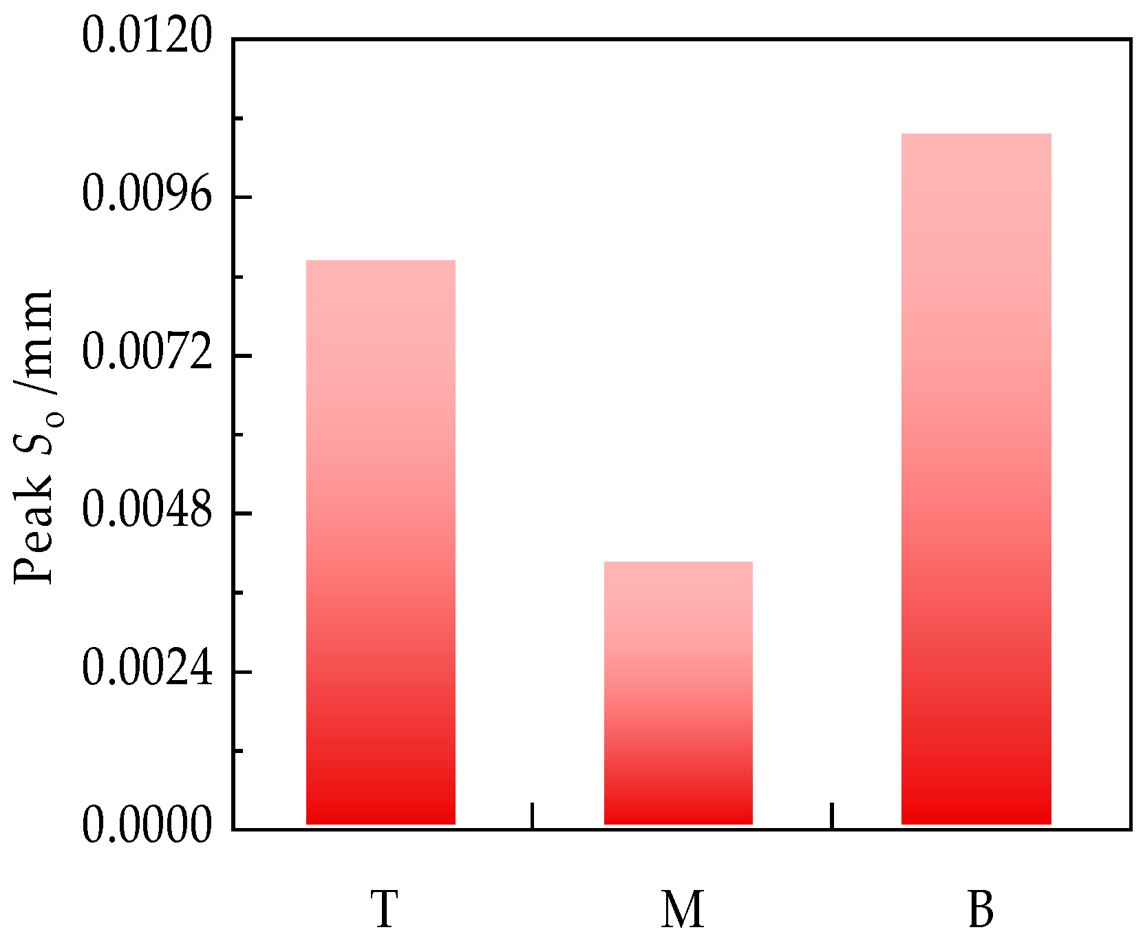
So) was employed as an evaluation indicator.
So quantifies the normal separation distance of the interface. Positive values indicate interfacial opening and separation, which may interrupt stress transfer and reduce lateral tensile strain transfer capability. Negative values indicate interfacial compression, which may cause local fiber buckling or stress concentration. The calculation method is shown in Equation (3):
where
is the normal displacement of the slave surface node (mm);
is the normal displacement of the corresponding point on the master surface (mm);
is the initial gap (mm).
To evaluate the monitoring stability of UWFBG sensors under loading conditions, D and So were jointly regarded as monitoring stability indicators. Specifically, D reflects the degradation of interfacial bonding capacity due to damage evolution, while So reflects variations in the interfacial normal separation state induced by opening or compression. Together, they determine the continuity and stability of interfacial stress transfer, thereby affecting the reliability of sensor output and long-term monitoring performance.
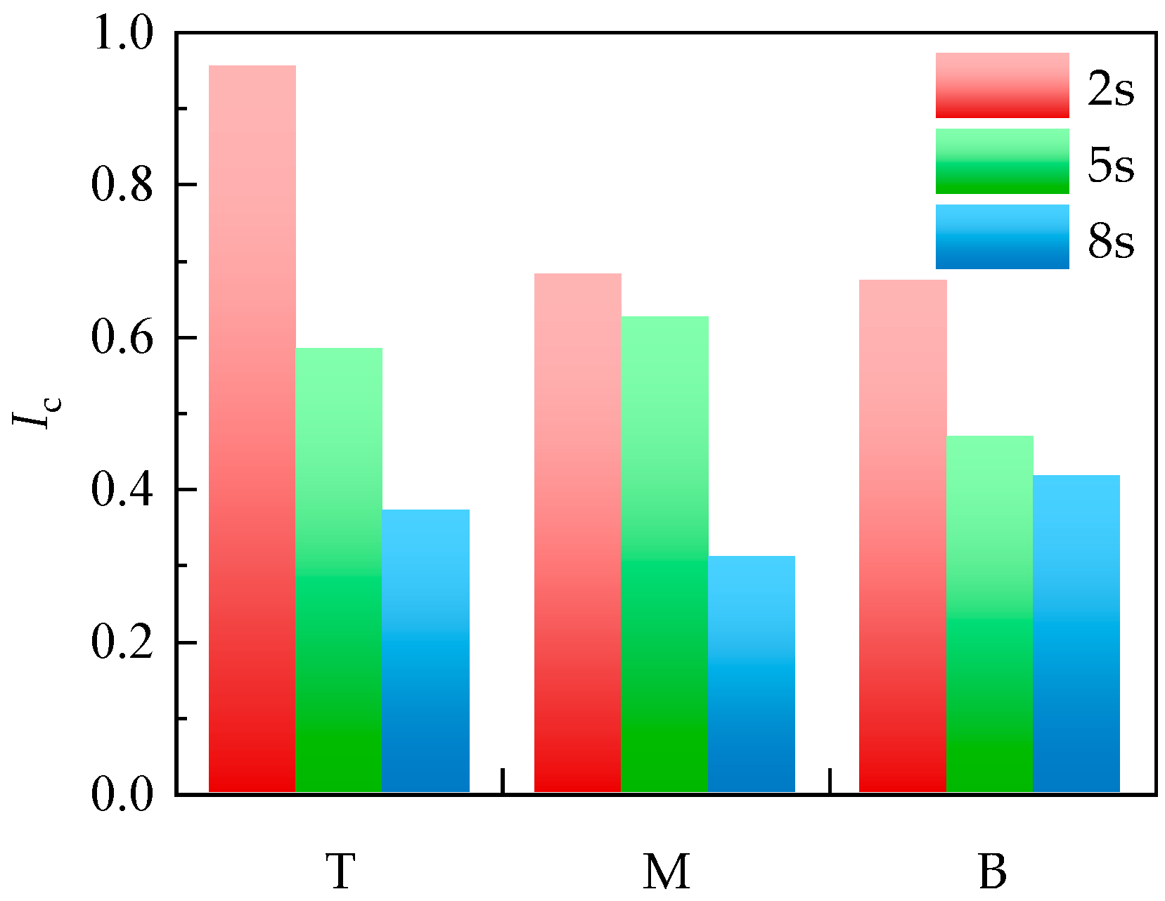
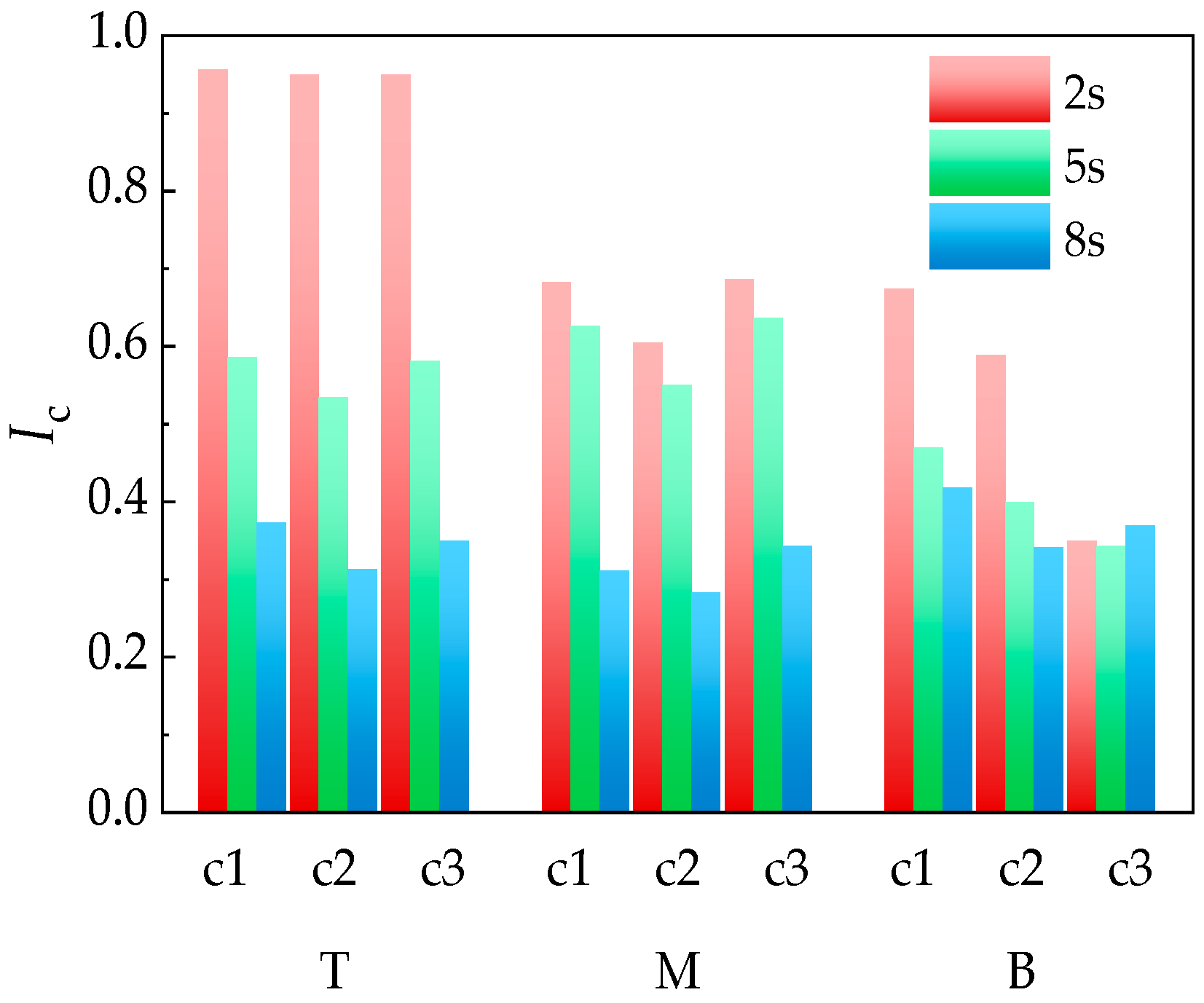
To comprehensively evaluate the deformation coordination performance of UWFBG sensors under different embedding positions, a standardized and weighted comprehensive evaluation method was adopted to integrate the three key indicators, and a deformation coordination index (
Ic) was constructed. To eliminate dimensional differences among indicators, an min–max normalization method was adopted. For any indicator
, the normalized value is defined as
where
X denotes the actual value of these indicators, including the lateral tensile strain change rate of the UWFBG core, the interface damage degree, and the interface opening displacement;
Xmax and
Xmin denote the maximum and minimum values of these indicators, respectively;
X* is the dimensionless normalized indicator.
After normalization, all indicators ranged from 0 to 1. To determine the relative importance of the evaluation indicators, an Analytic Hierarchy Process (AHP) was adopted to calculate the weight coefficients. AHP is widely used in multi-criteria decision analysis and determines indicator weights through pairwise comparison and consistency verification. In this study, deformation coordination between the UWFBG sensor and the surrounding asphalt mixture is evaluated using three indicators: the lateral tensile strain change rate of the UWFBG core, the interface damage degree, and the interface opening displacement. Based on engineering judgment and the mechanical significance of these indicators, pairwise comparisons were performed using the Saaty scale. The strain change rate of the UWFBG core was considered slightly more important than the other indicators because it directly reflects the strain response sensitivity of the embedded sensor. The interface damage degree was regarded as slightly more important than the interface opening displacement, as it characterizes the degradation of load transfer capacity at the sensor–asphalt interface. The pairwise comparison matrix used in the AHP analysis is shown in
Table 8.
Through eigenvalue calculation and normalization of the judgment matrix, the weight coefficients of the three indicators were obtained. The lateral tensile strain change rate of the UWFBG core was assigned a weight of 0.42 (
), the interface damage degree was assigned a weight of 0.33 (
), and the interface opening displacement was assigned a weight of 0.25 (
). The consistency ratio of the judgment matrix was calculated and found to be less than 0.1, indicating that the judgment matrix satisfies the consistency requirement of the AHP method. The weighted deformation coordination index
Ic is expressed as
where
,
, and
are the normalized lateral tensile strain change rate of the UWFBG core, the normalized interface damage degree, and the normalized interface opening displacement, respectively. The deformation coordination index
Ic ranges from 0 to 1, with larger values indicating better deformation compatibility between the fiber and the mixture.
2.5. Research Framework
Based on the modeling approach described in
Section 2.2 and the index construction method presented in
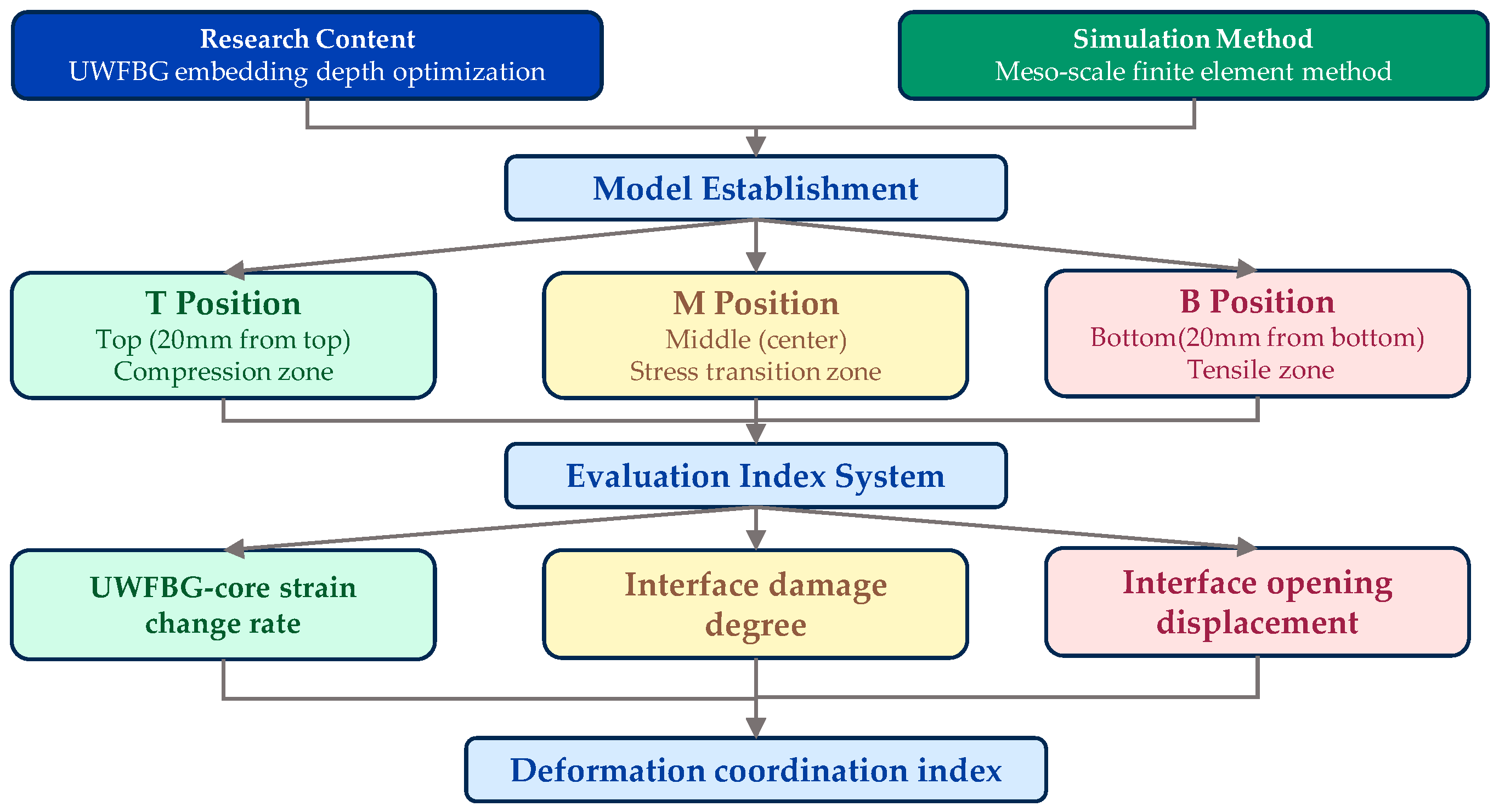
Section 2.3, a numerical simulation and evaluation procedure was established to analyze the deformation coordination mechanism under different vertical embedding positions. To improve the clarity of the methodology, a flowchart illustrating the research procedure is presented in
Figure 4, which summarizes the main steps of the study, including mesoscale finite element model construction, parameter extraction, evaluation index establishment, and deformation coordination index calculation.
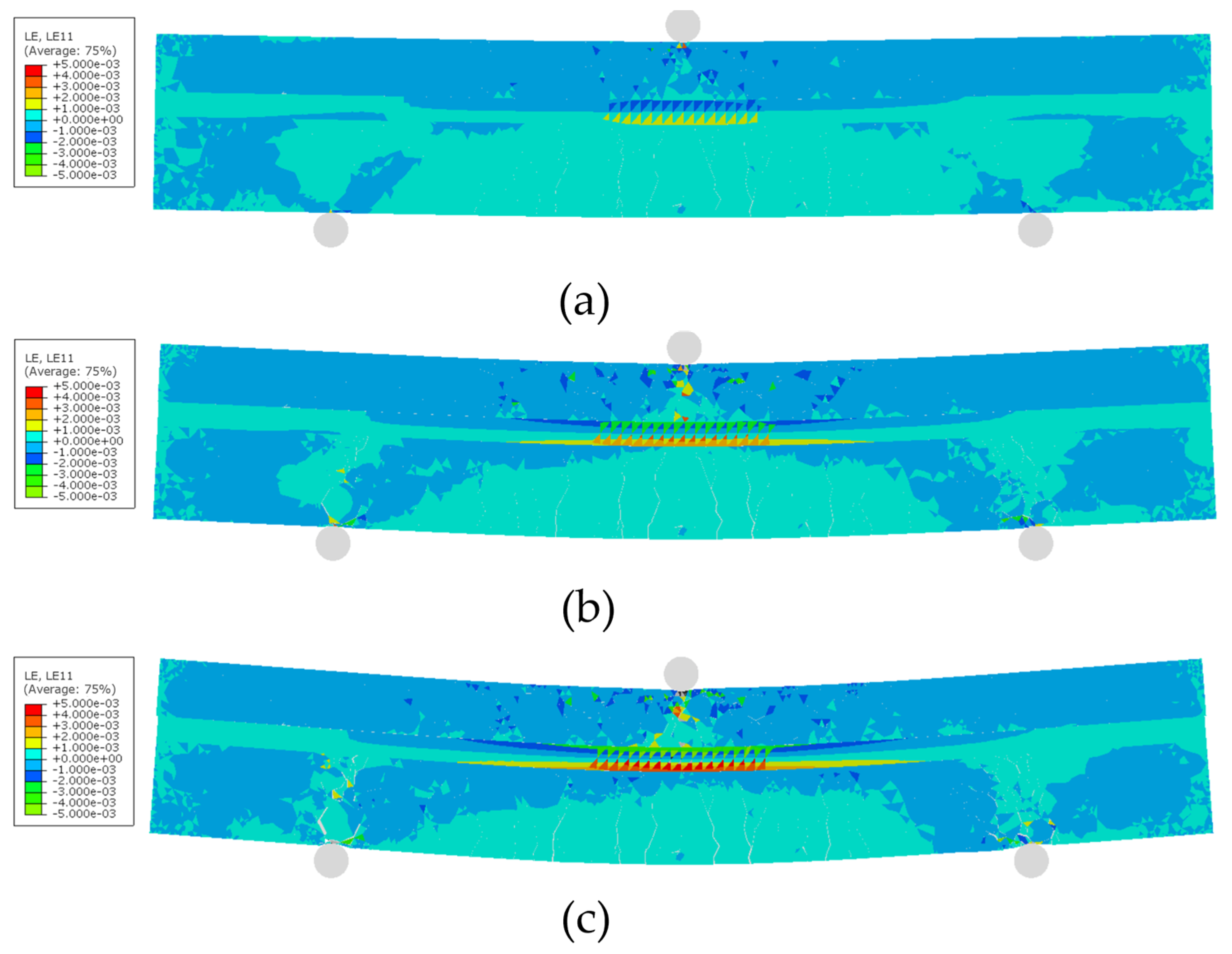
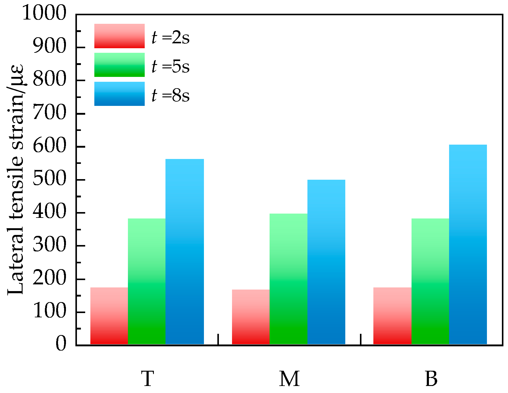
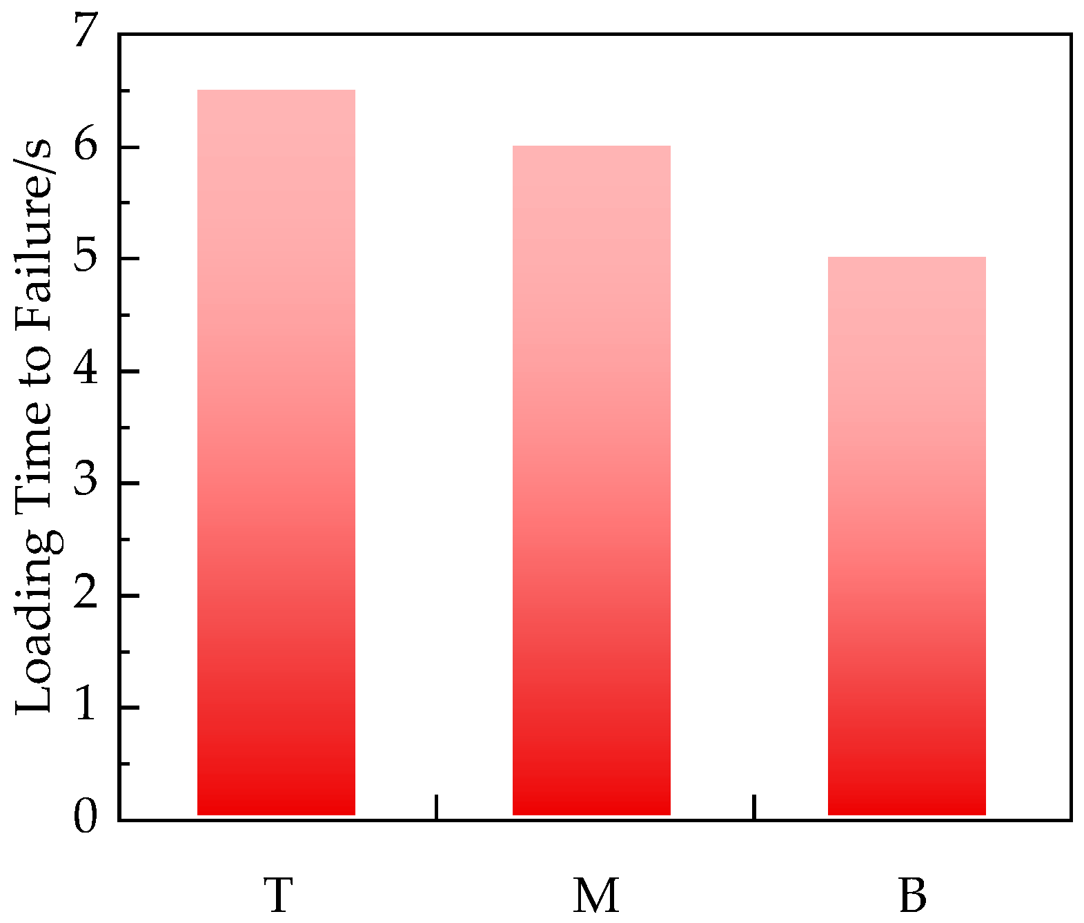
This study aims to reveal the mechanical coordination mechanism between the asphalt mixture and the UWFBG sensors with different embedding positions. To do this, a numerical scheme that is capable of capturing nonlinear deformation and progressive interfacial degradation throughout the entire loading process is required. Moreover, in order to simulate the complete mechanical response of the UWFBG sensor–asphalt mixture system, a mesoscale finite element modeling approach was adopted, and an explicit dynamic solver with quasi-static loading control was employed. The total loading duration was set to 10 s, covering the elastic stage, the elastic–plastic transition stage, and the plastic failure stage. Representative time instants at 2 s, 5 s, and 8 s were selected according to the lateral tensile strain field evolution, ensuring that each time point corresponded to a distinct mechanical stage.
With the simulation strategy and stage division established, the next step (Model Establishment) in the framework is to construct comparable embedding configurations under strictly controlled conditions. To isolate the influence of vertical embedding position, three embedding configurations were analyzed: top (T), middle (M), and bottom (B). To ensure comparability, all models shared identical geometric dimensions, material parameters, interfacial properties, and loading conditions. The only variable was the vertical embedding position of the UWFBG sensor.
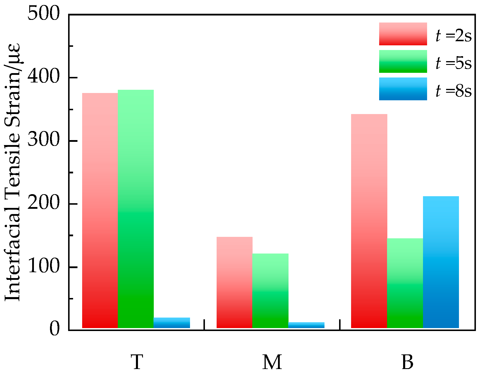
Once the embedding models were established under unified conditions, the framework proceeds to the “evaluation index system.” Since the objective is to evaluate deformation compatibility, it is necessary to extract parameters that simultaneously reflect sensor strain sensitivity and interfacial degradation behavior. To ensure consistency and minimize boundary-induced disturbances, a unified parameter extraction strategy was adopted. All interfacial response parameters (including interfacial lateral tensile strain, interface damage degree, and interface opening displacement) were extracted at the central point of the lower UWFBG sensor–asphalt contact interface. Meanwhile, to characterize the intrinsic strain response behavior of the sensor, the lateral tensile strain within the UWFBG core and its change rate were extracted along the sensor axis. At each representative stage (2 s, 5 s, and 8 s), three key indicators were obtained: (1) lateral tensile strain change rate within the UWFBG core; (2) interface damage degree; (3) interface opening displacement. Together, these indicators form the evaluation index system.
After establishing the evaluation index system, the final step in the framework is the construction of the “deformation coordination index.” Since the extracted indicators differ in magnitude and dimension, direct comparison is not feasible. Therefore, all indices were first normalized using the min–max method to eliminate dimensional discrepancies. Subsequently, weights were assigned based on the mechanical relevance of each indicator to deformation coordination. Through weighted integration, the deformation coordination index was constructed to quantitatively evaluate the compatibility between the UWFBG sensor and the asphalt mixture under different embedding positions. Through this procedure, the relationship between the lateral tensile strain response sensitivity, interfacial degradation, and overall deformation compatibility was quantified.